for main spindle drives on machine tools with efficiency
TRANSCRIPT

For main spindle drives
on machine tools
With efficiency-optimized
direct drive design
PS Two-speed gear box
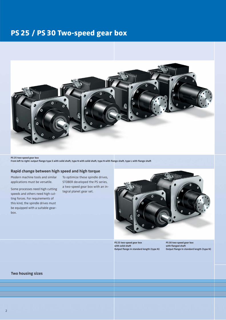
PS 25 / PS 30 Two-speed gear box
2
PS 25 two-speed gear boxFrom left to right: output flange type S with solid shaft, type N with solid shaft, type N with flange shaft, type L with flange shaft
PS 25 two-speed gear boxwith solid shaftOutput flange in standard length (type N)
PS 30 two-speed gear box with flanged shaftOutput flange in standard length (type N)
Rapid change between high speed and high torque
Modern machine tools and similar
applications must be versatile.
Some processes need high cutting
speeds and others need high cut-
ting forces. For requirements of
this kind, the spindle drives must
be equipped with a suitable gear-
box.
To optimize these spindle drives,
STOBER developed the PS series,
a two-speed gear box with an in-
tegral planet gear set.
Two housing sizes

The energy-saving solution for main spindle drives
3
Direct mode (mode 1) –
for high speed
This mode is designed as a direct
drive (ratio i = 1).
A new feature of the STOBER de-
sign is that the planet gear set is
fully decoupled at this stage and
therefore power loss is prevented.
The motor torque is transmitted
almost without loss, as if there
were no gearbox in between.
Position ratio i = 1, optimized direct drive
Position with planetary gear unit in operationratio i = 4 (5.5)
PS 25 two-speed gear boxwith short solid shaft output
High torque levels are needed for
the cutting of hard materials or for
for heavy-duty machining. Mode 2
activates the integral helical plane-
tary gear unit (ratio i = 4 or 5.5) to
obtain torque of up to 2 200 Nm.
Reduction mode (mode 2) –
for high torque
Oil seal at the coupling hub with small diameter for low friction or potential use of higher speeds
This newly designed two-speed gear box improves
the energy efficiency of machine tools The almost optimized operation in
direct drive mode, the friction mini-
mized helical planet gear set in re-
duction mode and the small-size
oil seal create the conditions for
significantly improving the energy
efficiency and noise emissions of
a spindle drive.
Torq
ue [N
m]
ratio i = 4 or 5.5Torque (POWER) required for high cutting forces (heavy-duty machining)
i = 1 High speeds (SPEED) required for finishing cuts
Speed [rpm]

Modular output design
4
Output flange type N
Output flange type L
Output flange type S
Application: Solid shaft for
direct mounting (S)
If the machine tool is used predom-
inantly for processes at high speeds,
direct mounting of the gearbox
with solid shaft is available.
Application: Flanged shaft
for belt drives
For transmission of high torque
levels, the conventional design
with belt drive offers the advan-
tage of minimizing vibration in
the system.
Output flange in
standard length (N)
This design is suitable for standard
belt pulleys. The overhung loads
are absorbed by cylindrical roller
bearings.
Output flange in
long version (L)
with wide bearing base
This version is suitable for use with
very large pulleys. When the cooling
flange is installed the neck length is
reduced, it then corresponds to that
of the output flange type N.
To absorb the high overhung loads,
the cylindrical roller bearing base is
made to the maximum width.
PS 25 two-speed gear box Output flange type L
External liquid cooling flange with large pulley for the main spindle drive

Universally usable
5
Suitable for vertical and
horizontal installation
The variety of mounting positions
enables the gearbox to be used
horizontally (for lathes) or verti-
cally (for machining centres).
Good use can also be made of the
specific advantages of this type of
gearbox in special purpose machine
manufacture.
Mounting positions
Fixing
Mounting holes on the housing foot (above)or for fitting on the bearing housing with centring (below)
Highly rigid, self-centring
motor connection
ME motor adapter with balanced
EasyAdapt® coupling for the attach-
ment of motors with plain shaft
(standard version).
Sealed design with hub bearing
and oil seal.
Standard motor connectionwith ME motor adapter
and EasyAdapt® coupling

Lubrication, cooling, electrical connection
6
Optional liquid cooling
For applications with very high
heat development, the cooling ef-
fect of the splash or recirculating
lubrication may not be sufficient.
With the optional cooling flange,
liquid cooling can be supplied to
the gearbox.
The liquid cooling option also re-
duces the heat given off to the
machine spindle or machine.
When the cooling flange is installed
the usable neck length of the out-
put flange then requires attention.
PS 30 two-speed gear box with long output flange.Due to the cooling flange adaptation (front of photo), the usable length of the flange is reduced
Section: Optional cooling flange forliquid cooling on a PS 25 two-speed gear box
Splash lubrication
For standard applications with fre-
quent alternation of the two speed
modes; interval speed changes and
when the machine is idle due to re-
tooling operations, splash lubrica-
tion in the sealed gear housing is
most suitable.
ConnectionRecirculating lubrication
With high heat development it
might be available (at maximum
heat levels) to add lubrication for
heat dissipation. The capacity of
the external tank must then be at
least ten times the volume of the
gearbox fill. If required, the tank fill
can be brought to an optimum op-
erating temperature through an
additional heat exchanger.
The oil inlet and outlet positions
depend on the selected mounting
position.Connector for 24V electronic speed changer
Oil sight glass
b1H7 e1 c �Q1 g d2max I5max
PS25PS30
230 265 95 250 M12 55 110
250 300 95 260 M16 55 110
300 350 95 315 M16 55 110
300 350 125 315 M16 60 140
PS 25 PS 30
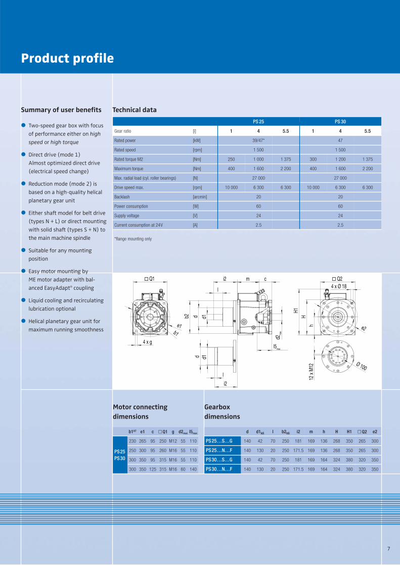
Gear ratio [i] 1 4 5.5 1 4 5.5
Rated power [kW] 39/47* 47
Rated speed [rpm] 1 500 1 500
Rated torque M2 [Nm] 250 1 000 1 375 300 1 200 1 375
Maximum torque [Nm] 400 1 600 2 200 400 1 600 2 200
Max. radial load (cyl. roller bearings) [N] 27 000 27 000
Drive speed max. [rpm] 10 000 6 300 6 300 10 000 6 300 6 300
Backlash [arcmin] 20 20
Power consumption [W] 60 60
Supply voltage [V] 24 24
Current consumption at 24V [A] 2.5 2.5
d d1k6 l b2h6 i2 m h H H1 �Q2 e2
PS25…S…G 140 42 70 250 181 169 136 268 350 265 300
PS25…N…F 140 130 20 250 171.5 169 136 268 350 265 300
PS30…S…G 140 42 70 250 181 169 164 324 380 320 350
PS30…N…F 140 130 20 250 171.5 169 164 324 380 320 350
Gearbox
dimensions
Motor connecting
dimensions
Product profile
7
Technical dataSummary of user benefits
Two-speed gear box with focus
of performance either on high
speed or high torque
Direct drive (mode 1)
Almost optimized direct drive
(electrical speed change)
Reduction mode (mode 2) is
based on a high-quality helical
planetary gear unit
Either shaft model for belt drive
(types N + L) or direct mounting
with solid shaft (types S + N) to
the main machine spindle
Suitable for any mounting
position
Easy motor mounting by
ME motor adapter with bal-
anced EasyAdapt® coupling
Liquid cooling and recirculating
lubrication optional
Helical planetary gear unit for
maximum running smoothness
�
�
�
�
�
�
�
�
cmi2
d d1b2
b1e1
4 x g
H1
d2m
ax
l5max
hH
e2
12 x
M12 Ø 100
Q24 x Ø 18
Q1
l
d1
i2
d
l
*flange mounting only

www.stober.com
STÖBER ANTRIEBSTECHNIK GmbH + Co. KG
Kieselbronner Str. 12
75177 PFORZHEIM
GERMANY
Phone +49 7231 582-0
Fax +49 7231 582-1000
www.stoeber.de
STOBER DRIVES LTD.CANNOCK WS12 2HA
UNITED KINGDOM
STOBER DRIVES, INC.MAYSVILLE, KY 41056
USA
STÖBER ANTRIEBSTECHNIK GmbH4663 LAAKIRCHEN
AUSTRIA
STOBER CHINABEIJING 100004
CHINA
STOBER S.a.r.l.69300 CALUIRE ET CUIRE
FRANCE
STOBER offers consistent
solutions
As a system supplier STOBER has a
complete product range for digital
drive technology. The MC6 motion
controller uses the CODESYS pro-
gramming software to keep up
with the trend towards open sys-
tems in the world of automation.
In combination with digital servo
axes, STOBER solutions can be used
for small or more extensive drive
applications.
Note on the design of axes
and drives
For optimum axis design, it makes
sense to focus primarily on the gear
units or geared motors. A useful aid
is the design software SERVOsoft
which you can download from the
STOBER website (PRODUCTS > Soft-
ware/Download > SERVOsoft).
For an overall approach, use the
specific expertise of the STOBER
application consultants.
Contact and advice:
STÖBER TRASMISSIONI S.r.l.20017 RHO (MI)
ITALY
STOBER Japan K. K.TOKYO
JAPAN
STOBER Singapore Pte. Ltd.SINGAPORE 787494
SINGAPORE
STÖBER Schweiz AG5453 REMETSCHWIL
SWITZERLAND
In general, the service specialists
can be reached at any time via a
24/7 service hotline.
When necessary, a problem can be
addressed immediately.
24/7 service hotline
+49 180 5 786323
Service
The STOBER service system compri-
ses 38 expert partners in Germany
and more than 80 companies in
the STOBER SERVICE NETWORK
worldwide.
This service concept guarantees
local expertise and availability
when needed.
Su
bje
ct t
o t
ech
nic
al
cha
ng
es
44
25
12
.00
3
00
0
09
/13
w
ww
.wa
st.d
e