bearing selection for high efficiency worm gear drives
TRANSCRIPT
111
Bearing Selection for High Efficiency Worm Gear Drives Manuel Oehler 1, Michel Werner 2, Bernd Sauer 3
1 Institute for Machine Elements, Gears, and Transmissions, Technische Universität Kaiserslautern, [email protected]
2 Institute for Machine Elements, Gears, and Transmissions, Technische Universität Kaiserslautern, [email protected]
3 Institute for Machine Elements, Gears, and Transmissions, Technische Universität Kaiserslautern, [email protected]
Abstract – In worm gearboxes, several machine elements cause different portions of the total power loss. Besides the load-dependent losses of the gears the losses of the bearings on the worm shaft contribute largely to the total power loss. Main reasons are high axial loads and high speeds compared to the worm wheel shaft due to commonly high gear ratios. In this work, comparative studies are shown in which different bearing setups are applied to a worm gear drive. Example setups are tapered roller bearings or angular contact ball bearings in adjusted bearing arrangement as well as a locating/non-locating bearing arrangement using four-point contact bearing as locating bearing. A tribological simulation software is used to calculate the load on the worm shaft bearings in axial and radial direction depending on the load situation of the gearbox (torques and speeds at the input and output shaft). Simu-lative studies show how different bearings perform under several conditions regarding rating life and power loss. Additionally, experimental tests are carried out to show the influence of bearing choice on the total efficiency of the gearbox. It is shown in both simulation and experiment that the use of angular contact ball bearings results in significant lower power losses compared to tapered roller bearings. However, compromises must be accepted re-garding the bearing life. One aspect that is not considered in this work is the influence of the bearing selection on the worm shaft deflection under load, which also can play an important role.
Keywords – Efficiency, power loss, worm gears, bearing selection
1. IntroductionCompared to other types of gears, worm gears are characterized by the large gear ratios up to more than 100 that can be realized in one single stage, the sim-ple design, the high overload capacity as well as a low-vibration and low-noise running behaviour [1]. Contrary to the widespread assumption that worm gears are associated with low efficiency, this effi-ciency has always been comparable to that of other types of gears at low transmission ratios [2]. Tech-nological developments in manufacturing and lubri-cant technology over the last few decades have made it possible to achieve a large increase in efficiency at all ranges of transmission ratios, which can be seen, for example, in the elimination of fans and fins on gearbox housings. For example, considering gear ra-tios 𝑖 ≤ 10, overall efficiencies of up to 𝜂G = 97 % can be achieved with worm gears [3]. Nevertheless, the efficiency of worm gearboxes can be increased even further through targeted optimization. The se-lection of a suitable bearing arrangement concept can make an important contribution to increasing the efficiency of the gearbox.
Here it is purposeful to focus on the bearings of the worm shaft, since comparatively high speeds are present here and high axial forces must be absorbed from the tooth contact. In contrast, the worm gear bearing arrangement mainly absorbs radial forces at significantly lower speeds, depending on the trans-mission ratio. High axial loads lead to a relatively large amount of sliding friction in the bearing of the
worm shaft, where tapered roller bearings (sliding friction in roller end–flange contacts) or angular con-tact bearings (spinning friction) are commonly used. Accordingly, a large part of the bearing power loss occurs at the position of the worm shaft, whereas the worm wheel bearings make only a small contribution to this.
Investigations into the reduction of gearbox power losses by adapting the bearing arrangement concept have already been shown for various types of gear-boxes. Specific measures, such as the use of angular contact ball bearings instead of tapered roller bear-ings, can increase the gear efficiency in spur gear units [4] and car rear axle gears [5]. Worm gears place different demands on the bearing arrangement than, for example, spur gears, which is why this pa-per shows how a systematic consideration of bearing power loss and bearing service life can be used to select the most efficient concept for the bearing ar-rangement of the worm shaft.
2. State of the artNumerous works by various authors are available on the design and layout of worm gearboxes. In [6], an overview of the design of worms and worm gears with the aspects material selection, manufacturing and efficiency is given. Another comprehensive work on the calculation, design and manufacture of worm gears is [7]. In [8], the design of the gearing is discussed as well as the housing design and the measurement of gearing deviations. Examples and
Manuel Oehler et al.– Bearing World Journal Vol. 5 (2020) page 111 – page 121
112
notes on possible bearing arrangement concepts are described in [9].
A standardized calculation method for determining the friction in the tooth contact of worm gears is de-scribed in DIN 3996 [10]. It also contains a method for the general calculation of forces in tooth contact. Standards at the international level are for example [11] and [12]. There, equations are given for effi-ciency and for the thermal capacity of gearboxes. Ta-bles for selection of gearing geometries as well as calculation rules and examples of load capacity are shown in [13]. In [14] a calculation method for the efficiency of worm gears is included, which is based on empirically determined, speed-dependent coeffi-cients of friction. A comparison of the various stand-ardized calculation methods for efficiency calcula-tion is shown in [15] using worm gears with centre distances of 50 and 150 mm. It becomes obvious that there are very big differences between the different standardized calculation methods as well as between standard and experiment.
Basic works for the computational determination of the efficiency of worm gears are for example [16], [17] and [18].
In [19] experiments on the influence of the lubricant on wear and efficiency are shown and empirical equations for the determination of bearing losses are described. In [20] the load-dependent and load-inde-pendent losses of different components in worm gears are determined by means of tests. On the basis of these tests, approximate formulas are derived for the power loss of the bearing at the worm shaft, among other things. The determination of the bear-ing forces from the gearing forces using the basic rules of engineering mechanics is shown in [21].
3. Power losses in worm gearboxes In worm gears, losses are caused by the gear teeth, the bearings and the rotating shaft seals. Since there are no clutches or other additional components in common worm gearboxes, other losses can be ig-nored. According to ISO TR 14179-2 [11], these losses can be divided into load-independent (0) and load-dependent (P). 𝑃 𝑃 , 𝑃 , 𝑃 , 𝑃 , 𝑃
𝑃 (Eq. 1)
In Eq. 1, the index "Z" stands for gearing, "L" for bearing, "D" for seals and "X" for other loss sources.
Under nominal load, the load-dependent losses of the gears 𝑃 , are usually responsible for a large part of the losses. However, bearing losses 𝑃 can also contribute significantly to the total losses 𝑃 . In partial load operation, their share can even be greater than that of the gears. The bearings on the worm shaft play a much greater role than the bearings on the worm wheel shaft due to the higher rotational speed and large axial load [20, 22]. The bearing
losses in operation can be considerably reduced by a specific design of the worm bearing, thus improving the efficiency of the gearbox.
4. Bearing setups used in worm gearboxes For the bearing arrangement of the worm shaft, mostly adjusted bearings in X-arrangement or locat-ing/non-locating bearing combinations are used [23]. Since the worm shaft bearings absorb the high axial forces from the gears, tapered roller bearings or angular contact ball bearings are used. Radial loads dominate at the bearing of the worm wheel shaft, which is why deep groove ball bearings are often used here. In the case of bearings of the worm shaft, the most important selection criteria with regard to function are, in addition to power loss, the stiffness of the bearing arrangement and the bearing life. Notes on the functional selection of bearing arrange-ments in worm gearboxes can be found in [24], for example.
5. Theoretical studies on various bearing setups
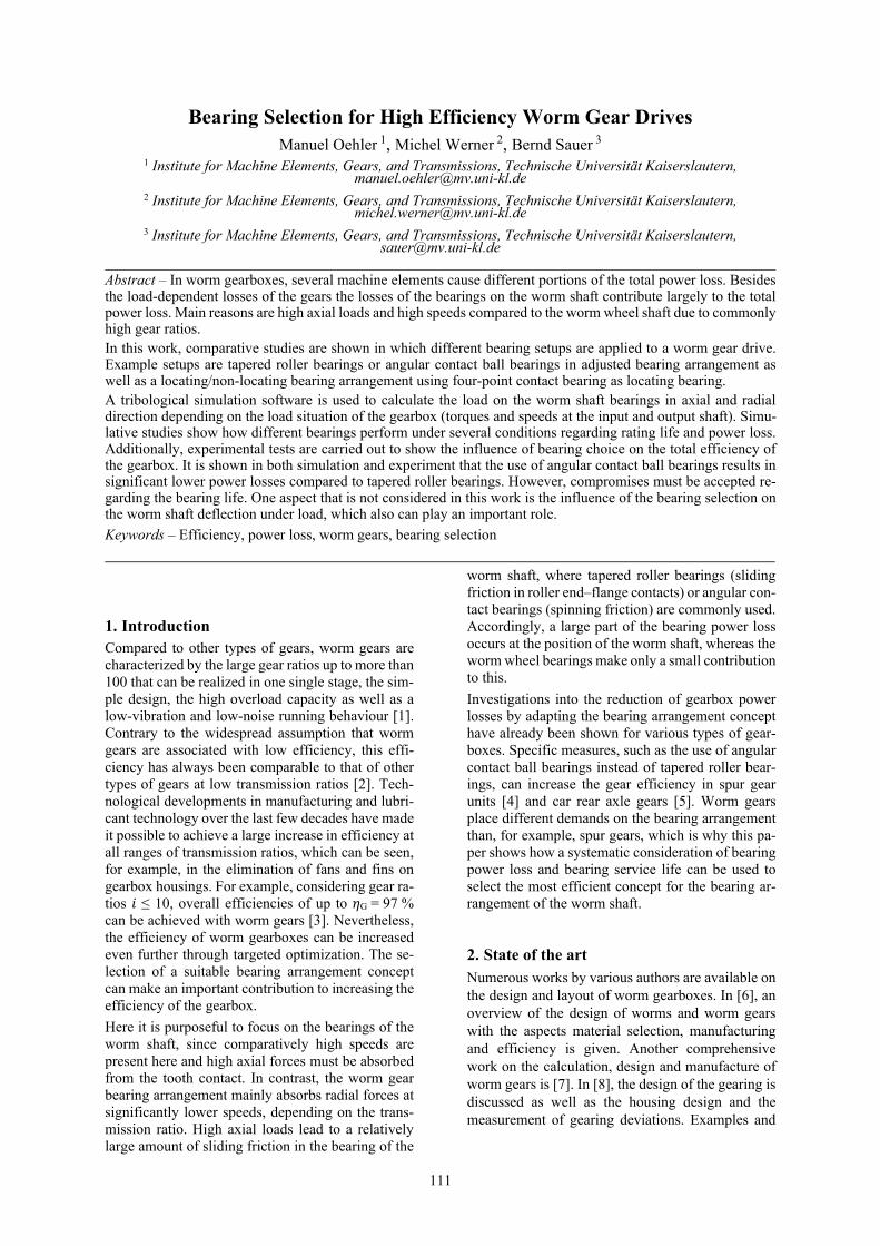
In order to be able to assess various bearing arrange-ment concepts from the point of view of efficiency, a comprehensive study was carried out. For this pur-pose, a calculation program was set up which, in ad-dition to calculating the bearing power loss PVL ac-cording to the SKF model [25], also allows the mod-ified rating life L10mh of the bearings to be deter-mined according to DIN ISO 281 [26].
The methodology for calculating the bearing power loss and bearing life is described in [22]. With the help of a physical model, the local normal and fric-tional forces in the tooth contact of worm gears can be calculated. These depend, among other things, on the external load, the gear geometry, the surfaces of the gear teeth and the lubricant used. The bearing forces can be determined from the tooth contact forces, which in turn serve as input values for the bearing power loss and bearing life calculation.
The method for determining the bearing forces by integrating the local forces in tooth contact over all contact lines currently in engagement is described in [27] and [22]. Since the meshing situation and the position of the contact lines of worm gears changes periodically, the bearing forces also fluctuate period-ically. For the studies on bearing life and power loss, the bearing forces averaged over all meshing posi-tions were used.
Thus it is possible to evaluate these two target values for different bearing configurations for any worm gearbox under defined conditions.
Fig. 1 illustrates the process of the calculation method from the tribological simulation of the tooth contact to determination of bearing power loss and rating life.
Manuel Oehler et al.– Bearing World Journal Vol. 5 (2020) page 111 – page 121
113
5.1. Gearbox with centre distance 100 mm
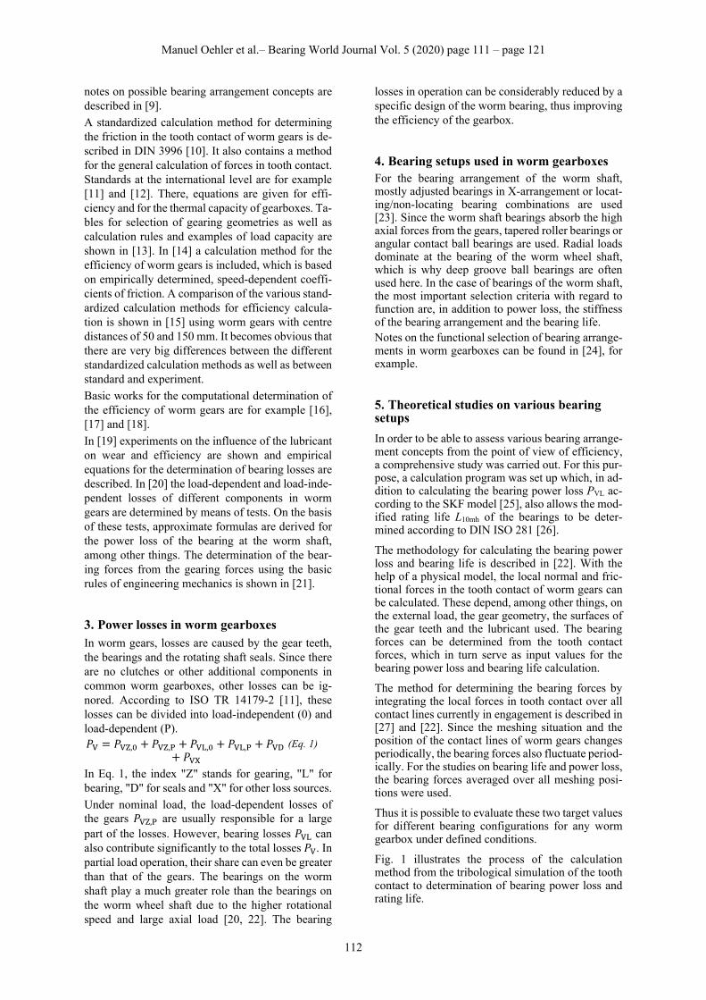
Fig. 2 shows the calculated power losses PV caused by the two bearings of the worm shaft, for different concepts. The following were investigated for a worm gear with centre distance a = 100 mm and gear ratio i = 20: tapered roller bearings with the designa-tions 31307, 31308, 32207 and 32208 as well as an-gular contact ball bearings with the designations 7307 and 7308 as adjusted bearings in X-arrange-ment. Four-point contact bearings with the designa-tions QJ 307 and QJ 308 together with deep groove ball bearings of the type 6307 or 6308 respectively were investigated as locating/non-locating bearing combinations. In addition, the combinations of axial cylindrical roller bearings with the designations 81107 TN, 81108 TN, 81207 TN and 81208 TN with deep groove ball bearings of the type 6307 or 6308 were examined. The light grey bars show the power loss PVL,12 of the axially loaded bearing. The dark grey bars show the power loss PVL,11 of the axially unloaded bearing. The height of the bars in the dia-gram therefore shows the total power loss that occurs at the bearings of the worm shaft. The boundary con-ditions for the calculation were an output torque of Tout = 700 Nm, an input speed of nin = 1400 min-1 and an oil sump temperature of ϑS = 80 °C when lubri-cated with a polyglycol oil of viscosity class ISO VG 460.
Figure 2: Sum of the calculated bearing power loss PVL of both bearings of the worm shaft and distribu-tion of the losses to the bearings L11 (no axial load) and L12 (carries axial load) for different bearing ar-rangement concepts on a worm gear with centre dis-tance a = 100 mm and gear ratio i = 20 operating at an output torque of Tout = 700 Nm, an input speed of nin = 1400 min-1 and an oil sump temperature of ϑS = 80 °C lubricated with a polyglycol oil of viscos-ity class ISO VG 460 at 80 °C
The evaluation of the power loss calculation shows that the adjusted bearing arrangement with angular contact ball bearings and the locating/non-locating bearing combination with four-point contact bear-ings are the most efficient variants. In comparison, the use of axial cylindrical roller bearings has higher power losses. Angular contact tapered roller bearing arrangements sometimes result in approximately twice as high losses as those using angular contact ball bearings of the same bore number. Tapered roller bearings of series 313 differ from bearings of series 322 by a larger outer diameter as well as a sig-nificantly larger contact angle and show a more fa-vourable behaviour than those with regard to power loss.
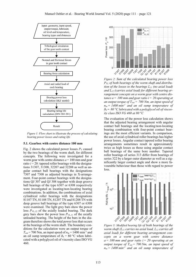
Figure 3: Modified bearing life of both bearings of the worm shaft (L11 carries no axial load, L12 carries all axial load) for different bearing arrangement con-cepts on a worm gear with centre distance a = 100 mm and gear ratio i = 20 operating at an output torque of Tout = 700 Nm, an input speed of nin = 1400 min-1 and an oil sump temperature of
Figure 1: Flow chart to illustrate the process of calculatingbearing power losses and rating life
Manuel Oehler et al.– Bearing World Journal Vol. 5 (2020) page 111 – page 121
114
ϑS = 80 °C lubricated with a polyglycol oil of viscos-ity class ISO VG 460 at 80 °C
Fig. 3 shows the modified bearing life L10mh for the bearing arrangement concepts described. According to [26], a contamination coefficient of eC = 0.5 was assumed for the calculation. A comparison of the modified bearing life L10mh for the axially loaded worm bearing shows that tapered roller bearings of series 313 achieve significantly higher values than the variants with angular contact ball bearings or four-point contact bearings. In the context of power loss, it is evident that the most efficient solutions do not achieve the longest life of all concepts, but the values are still at L10mh > 10,000 h. The use of sepa-rate axial and radial bearings in the form of axial cy-lindrical roller bearings and deep groove ball bear-ings is neither the best solution from the point of view of service life nor efficiency. In all variants, it has been shown that the selection of a smaller bore number has a positive effect on losses. This effect is particularly clear in the case of tapered roller bearing 313. On the other hand, the modified rating life also decreases with the reduction of the bearing size. Compared with series 322, tapered roller bearings of series 313 have a higher axial load carrying capacity due to the higher contact angle, which is also re-flected in the increased rating life.
5.2. Gearbox with centre distance 40 mm
In addition to the gearbox with 100 mm centre dis-tance, a comparatively small gearbox and a large gearbox with identical gear ratio were simulated. In the following, the results of the simulative study on bearing losses and rating life for a worm gearbox with centre distance a = 40 mm and gear ratio i = 20 are presented. Tapered roller bearings with the designations 30302 and 30303 as well as angular contact ball bearings with the designations 7302 and 7303 were used as adjusted bearings in X-arrangement. Four-point con-tact bearings with the designations QJ 202 and QJ 303 together with deep groove ball bearings of the type 6302 or 6303 were investigated as locating and non-locating bearing arrangements. Further combi-nations of locating/non-locating bearing arrange-ments, which appear to be particularly useful for smaller gearboxes, are the use of deep groove ball bearings both as locating and non-locating bearings, which was simulated with bearings of types 6303 and 6304. In addition, the combinations of radial cy-lindrical roller bearings with the designations NU 303 or NU 304 as floating bearings and deep groove ball bearings of types 6303 and 6304 as locating bearings were considered. For the worm gear, deep groove ball bearings of type 6206 were always used as adjusted bearings in X-arrangement.
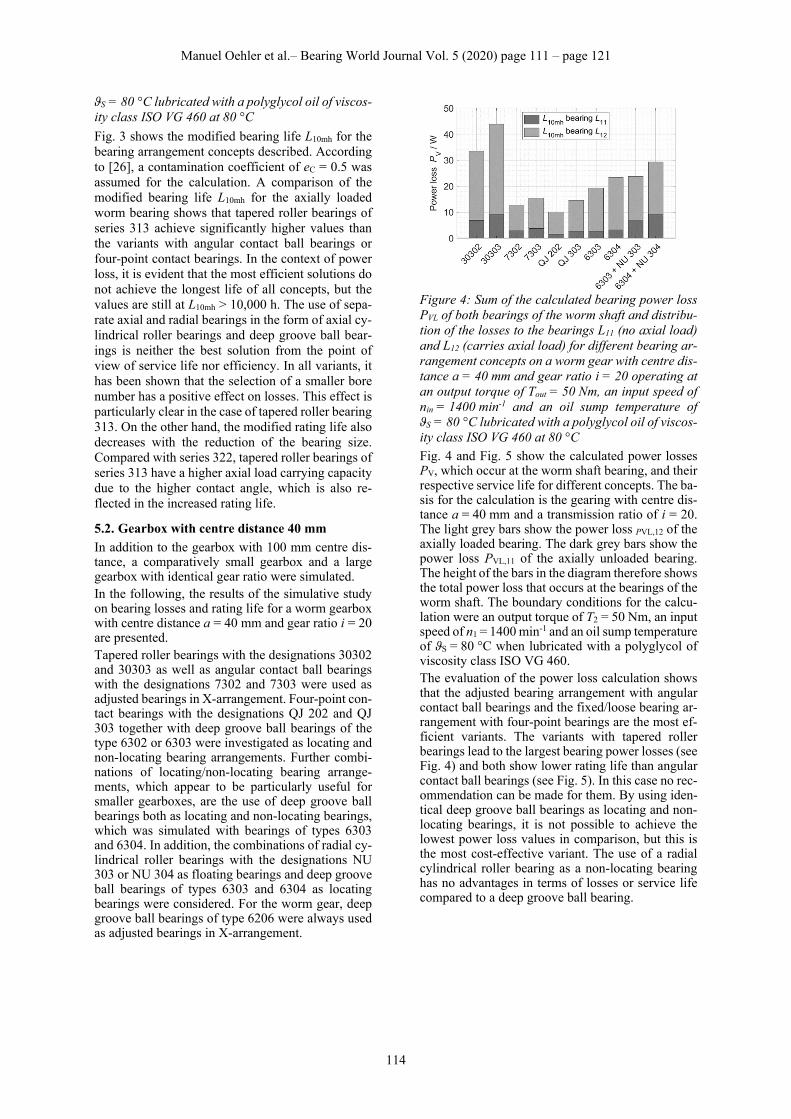
Figure 4: Sum of the calculated bearing power loss PVL of both bearings of the worm shaft and distribu-tion of the losses to the bearings L11 (no axial load) and L12 (carries axial load) for different bearing ar-rangement concepts on a worm gear with centre dis-tance a = 40 mm and gear ratio i = 20 operating at an output torque of Tout = 50 Nm, an input speed of nin = 1400 min-1 and an oil sump temperature of ϑS = 80 °C lubricated with a polyglycol oil of viscos-ity class ISO VG 460 at 80 °C
Fig. 4 and Fig. 5 show the calculated power losses PV, which occur at the worm shaft bearing, and their respective service life for different concepts. The ba-sis for the calculation is the gearing with centre dis-tance a = 40 mm and a transmission ratio of i = 20. The light grey bars show the power loss PVL,12 of the axially loaded bearing. The dark grey bars show the power loss PVL,11 of the axially unloaded bearing. The height of the bars in the diagram therefore shows the total power loss that occurs at the bearings of the worm shaft. The boundary conditions for the calcu-lation were an output torque of T2 = 50 Nm, an input speed of n1 = 1400 min-1 and an oil sump temperature of ϑS = 80 °C when lubricated with a polyglycol of viscosity class ISO VG 460. The evaluation of the power loss calculation shows that the adjusted bearing arrangement with angular contact ball bearings and the fixed/loose bearing ar-rangement with four-point bearings are the most ef-ficient variants. The variants with tapered roller bearings lead to the largest bearing power losses (see Fig. 4) and both show lower rating life than angular contact ball bearings (see Fig. 5). In this case no rec-ommendation can be made for them. By using iden-tical deep groove ball bearings as locating and non-locating bearings, it is not possible to achieve the lowest power loss values in comparison, but this is the most cost-effective variant. The use of a radial cylindrical roller bearing as a non-locating bearing has no advantages in terms of losses or service life compared to a deep groove ball bearing.
Manuel Oehler et al.– Bearing World Journal Vol. 5 (2020) page 111 – page 121
115
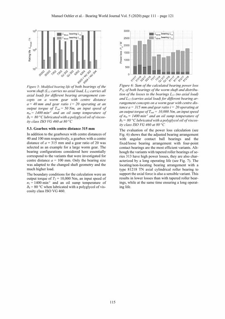
Figure 5: Modified bearing life of both bearings of the worm shaft (L11 carries no axial load, L12 carries all axial load) for different bearing arrangement con-cepts on a worm gear with centre distance a = 40 mm and gear ratio i = 20 operating at an output torque of Tout = 50 Nm, an input speed of nin = 1400 min-1 and an oil sump temperature of ϑS = 80 °C lubricated with a polyglycol oil of viscos-ity class ISO VG 460 at 80 °C
5.3. Gearbox with centre distance 315 mm
In addition to the gearboxes with centre distances of 40 and 100 mm respectively, a gearbox with a centre distance of a = 315 mm and a gear ratio of 20 was selected as an example for a large worm gear. The bearing configurations considered here essentially correspond to the variants that were investigated for centre distance a = 100 mm. Only the bearing size was adapted to the changed shaft geometry and the much higher load.
The boundary conditions for the calculation were an output torque of T2 = 10,000 Nm, an input speed of n1 = 1400 min-1 and an oil sump temperature of ϑS = 80 °C when lubricated with a polyglycol of vis-cosity class ISO VG 460.
Figure 6: Sum of the calculated bearing power loss PVL of both bearings of the worm shaft and distribu-tion of the losses to the bearings L11 (no axial load) and L12 (carries axial load) for different bearing ar-rangement concepts on a worm gear with centre dis-tance a = 315 mm and gear ratio i = 20 operating at an output torque of Tout = 10,000 Nm, an input speed of nin = 1400 min-1 and an oil sump temperature of ϑS = 80 °C lubricated with a polyglycol oil of viscos-ity class ISO VG 460 at 80 °C
The evaluation of the power loss calculation (see Fig. 6) shows that the adjusted bearing arrangement with angular contact ball bearings and the fixed/loose bearing arrangement with four-point contact bearings are the most efficient variants. Alt-hough the variants with tapered roller bearings of se-ries 313 have high power losses, they are also char-acterized by a long operating life (see Fig. 7). The locating/non-locating bearing arrangement with a type 81218 TN axial cylindrical roller bearing to support the axial force is also a sensible variant. This results in lower losses than with tapered roller bear-ings, while at the same time ensuring a long operat-ing life.
Manuel Oehler et al.– Bearing World Journal Vol. 5 (2020) page 111 – page 121
116
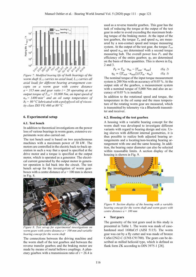
Figure 7: Modified bearing life of both bearings of the worm shaft (L11 carries no axial load, L12 carries all axial load) for different bearing arrangement con-cepts on a worm gear with centre distance a = 315 mm and gear ratio i = 20 operating at an output torque of Tout = 10,000 Nm, an input speed of nin = 1400 min-1 and an oil sump temperature of ϑS = 80 °C lubricated with a polyglycol oil of viscos-ity class ISO VG 460 at 80 °C
6. Experimental setup
6.1. Test bench
In addition to theoretical investigations on the power loss of various bearings in worm gears, extensive ex-periments were also carried out. The test bench used is based on two asynchronous machines with a maximum power of 30 kW. The motors are controlled in the electric back-to-back op-eration in such a way that a speed is specified at the drive motor and a torque is specified at the output motor, which is operated as a generator. The electri-cal current generated by the output motor in genera-tor operation is fed back into the circuit. The test bench set-up for the investigation of worm gear-boxes with a centre distance of a = 100 mm is shown in Fig. 8.
Figure 8: Test set-up for experimental investigations on worm gears with centre distance a = 100 mm and variable bearing concept for the worm shaft
The connections between the driving machine and the worm shaft of the test gearbox and between the reverse transfer gearbox and the braking motor are made by means of metal bellows couplings. A plan-etary gearbox with a transmission ratio of i = 26.4 is
used as a reverse transfer gearbox. This gear has the task of reducing the torque at the output of the test gear in order to avoid exceeding the maximum brak-ing torque of the braking motor. At the input of the test gearbox, the torque Tin and speed nin are meas-ured by a non-contact speed and torque measuring system. At the output of the test gear, the torque Tout and speed nout are determined with a second torque measuring hub. The overall power loss PV and the efficiency of the entire gearbox G are determined on the basis of these quantities. This is shown in Eq. 2 and 3.
𝑃 𝑇 ∙ 𝑛 |𝑇 ∙ 𝑛 | (Eq. 2)
𝜂 |𝑇 ∙ 𝑛 | / 𝑇 ∙ 𝑛 (Eq. 3)
The nominal torque of the input torque measurement system is 200 Nm with an accuracy of 0.05 %. At the output side of the gearbox, a measurement system with a nominal torque of 5,000 Nm and also an ac-curacy of 0.05 % is installed. In addition to the rotational speed and torque, the temperature in the oil sump and the mass tempera-ture of the rotating worm gear are measured, which is transmitted by telemetry via a Bluetooth transmit-ter and receiver.
6.2. Housing of the test gearbox
A housing with a variable bearing concept for the worm shaft was developed to investigate different variants with regard to bearing design and size. Us-ing sleeves with different internal geometries, it is thus possible to realize both adjusted bearing ar-rangements and a locating/non-locating bearing ar-rangement with one and the same housing. In addi-tion, the bearing outer diameter can also be selected within reasonable limits. A section display of the housing is shown in Fig. 9.
Figure 9: Section display of the housing with a variable bearing concept for the worm shaft and worm gears with centre distance a = 100 mm
Test gears
The geometry of the test gears used in this study is presented in Table 1. The worm was made of case-hardened steel 16MnCr5 (AISI 5115). The worm gear was cut by a fly cutter and was made of bronze CuSn12Ni2-C (UNS C91700). The gears can be de-scribed as milled helicoid type, which is defined as flank form ZK according to DIN 3975-1 [28].
Manuel Oehler et al.– Bearing World Journal Vol. 5 (2020) page 111 – page 121
117
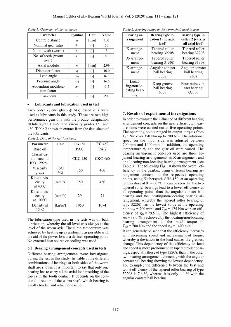
Table 1: Geometry of the test gears
Parameter Symbol Unit Value
Centre distance a [mm] 100
Nominal gear ratio iN [-] 20
No. of teeth (worm) z1 [-] 3
No. of teeth (worm gear)
z2 [-] 60
Axial module m [mm] 2.99
Diameter factor q [-] 10.0
Lead angle γm [-] 16.7
Pressure angle α0 [-] 16.5
Addendum modifica-tion factor
x2 [-] -1.5
Flank form - [-] ZK
Lubricants and lubrication used in test
Two polyalkylene glycol-(PAG) based oils were used as lubricants in this study. These are two high performance gear oils with the product designation "Klübersynth GH-6" and viscosity grades 150 and 460. Table 2 shows an extract from the data sheet of the lubricants. Table 2: Data of the test lubricants
Parameter Unit PG 150 PG 460
Base oil PAG PAG
Classifica-tion acc. to
ISO 12925-1 CKC 150 CKC 460
Viscosity grade
ISO VG
150 460
Kinem. vis-cosity
at 40°C [mm²/s] 150 460
Kinem. vis-cosity
at 100°C [mm²/s] 29 71
Density at 15°C
[kg/m³] 1050 1074
The lubrication type used in the tests was oil bath lubrication, whereby the oil level was always at the level of the worm axis. The sump temperature was achieved by heating up as uniformly as possible with the aid of the power loss at a defined operating point. No external heat source or cooling was used.
6.3. Bearing arrangement concepts used in tests
Different bearing arrangements were investigated during the test in this study. In Table 3, the different combinations of bearings at both sides of the worm shaft are shown. It is important to say that only one bearing has to carry all the axial load resulting of the forces in the tooth contact. It depends on the rota-tional direction of the worm shaft, which bearing is axially loaded and which one is not.
Table 2: Bearing setups at the worm shaft used in tests
Bearing ar-rangement
Bearing type lo-cation 1 (no axial
load)
Bearing type lo-cation 2 (carries
all axial load)
X-arrange-ment
Tapered roller bearing 32208
Tapered roller bearing 32208
X-arrange-ment
Tapered roller bearing 31308
Tapered roller bearing 31308
X-arrange-ment
Angular contact ball bearing
7308
Angular contact ball bearing
7308
Locat-ing/non-lo-cating bear-
ing
Deep groove ball bearing
6308
Four-point con-tact bearing
QJ308
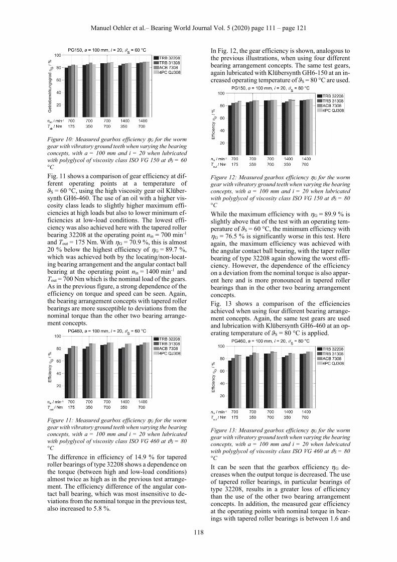
7. Results of experimental investigations In order to evaluate the influence of different bearing arrangement concepts on the gear efficiency, meas-urements were carried out at five operating points. The operating points ranged in output torques from 175 Nm over 350 Nm up to 700 Nm. The rotational speed on the input side was adjusted between 700 rpm and 1400 rpm. In addition, the operating temperature ϑS and the gear oil were varied. The bearing arrangement concepts used are three ad-justed bearing arrangements in X-arrangement and one locating/non-locating bearing arrangement (see Table 3). The following Fig. 10 shows the overall ef-ficiency of the gearbox using different bearing ar-rangement concepts at the respective operating points, using Klübersynth GH6-150, at an operating temperature of ϑS = 60 °C. It can be seen that the two tapered roller bearings lead to a lower efficiency at all operating points than the angular contact ball bearing and the locating/non-locating bearing ar-rangement, whereby the tapered roller bearing of type 32208 has the lowest value at the operating point nin = 700 min-1 and Tout = 175 Nm with an effi-ciency of G = 79.5 %. The highest efficiency of G = 89.0 % is achieved by the locating/non-locating bearing arrangement at the rated torque of Tout = 700 Nm and the speed nin = 1400 min-1. It can generally be seen that the efficiency increases with increasing speed and increasing load torque, whereby a deviation in the load causes the greatest change. This dependency of the efficiency on load and speed is more pronounced in tapered roller bear-ings, especially those of type 32208, than in the other two bearing arrangement concepts, with the angular contact ball bearing showing the lowest dependency. For example, the difference between the best and worst efficiency of the tapered roller bearing of type 32208 is 7.6 %, whereas it is only 4.4 % with the angular contact ball bearing.
Manuel Oehler et al.– Bearing World Journal Vol. 5 (2020) page 111 – page 121
118
Figure 10: Measured gearbox efficiency 𝜂G for the worm gear with vibratory ground teeth when varying the bearing concepts, with a = 100 mm and i = 20 when lubricated with polyglycol of viscosity class ISO VG 150 at 𝜗S = 60 °C
Fig. 11 shows a comparison of gear efficiency at dif-ferent operating points at a temperature of ϑS = 60 °C, using the high viscosity gear oil Klüber-synth GH6-460. The use of an oil with a higher vis-cosity class leads to slightly higher maximum effi-ciencies at high loads but also to lower minimum ef-ficiencies at low-load conditions. The lowest effi-ciency was also achieved here with the tapered roller bearing 32208 at the operating point nin = 700 min-1 and Tout = 175 Nm. With G = 70.9 %, this is almost 20 % below the highest efficiency of G = 89.7 %, which was achieved both by the locating/non-locat-ing bearing arrangement and the angular contact ball bearing at the operating point nin = 1400 min-1 and Tout = 700 Nm which is the nominal load of the gears. As in the previous figure, a strong dependence of the efficiency on torque and speed can be seen. Again, the bearing arrangement concepts with tapered roller bearings are more susceptible to deviations from the nominal torque than the other two bearing arrange-ment concepts.
Figure 11: Measured gearbox efficiency 𝜂G for the worm gear with vibratory ground teeth when varying the bearing concepts, with a = 100 mm and i = 20 when lubricated with polyglycol of viscosity class ISO VG 460 at 𝜗S = 80 °C
The difference in efficiency of 14.9 % for tapered roller bearings of type 32208 shows a dependence on the torque (between high and low-load conditions) almost twice as high as in the previous test arrange-ment. The efficiency difference of the angular con-tact ball bearing, which was most insensitive to de-viations from the nominal torque in the previous test, also increased to 5.8 %.
In Fig. 12, the gear efficiency is shown, analogous to the previous illustrations, when using four different bearing arrangement concepts. The same test gears, again lubricated with Klübersynth GH6-150 at an in-creased operating temperature of ϑS = 80 °C are used.
Figure 12: Measured gearbox efficiency 𝜂G for the worm gear with vibratory ground teeth when varying the bearing concepts, with a = 100 mm and i = 20 when lubricated with polyglycol of viscosity class ISO VG 150 at 𝜗S = 80 °C
While the maximum efficiency with G = 89.9 % is slightly above that of the test with an operating tem-perature of ϑS = 60 °C, the minimum efficiency with G = 76.5 % is significantly worse in this test. Here again, the maximum efficiency was achieved with the angular contact ball bearing, with the taper roller bearing of type 32208 again showing the worst effi-ciency. However, the dependence of the efficiency on a deviation from the nominal torque is also appar-ent here and is more pronounced in tapered roller bearings than in the other two bearing arrangement concepts. Fig. 13 shows a comparison of the efficiencies achieved when using four different bearing arrange-ment concepts. Again, the same test gears are used and lubrication with Klübersynth GH6-460 at an op-erating temperature of ϑS = 80 °C is applied.
Figure 13: Measured gearbox efficiency 𝜂G for the worm gear with vibratory ground teeth when varying the bearing concepts, with a = 100 mm and i = 20 when lubricated with polyglycol of viscosity class ISO VG 460 at 𝜗S = 80 °C
It can be seen that the gearbox efficiency 𝜂G de-creases when the output torque is decreased. The use of tapered roller bearings, in particular bearings of type 32208, results in a greater loss of efficiency than the use of the other two bearing arrangement concepts. In addition, the measured gear efficiency at the operating points with nominal torque in bear-ings with tapered roller bearings is between 1.6 and
Manuel Oehler et al.– Bearing World Journal Vol. 5 (2020) page 111 – page 121
119
3.4 % below the efficiency that can be achieved with a locating/non-locating bearing arrangement or a bearing arrangement with angular contact ball bear-ings. The efficiency of these two bearing arrange-ment concepts is similarly good, although slightly better results can be achieved with the use of angular contact ball bearings than with the locating/non-lo-cating bearing arrangement. At the operating point with nominal torque, the efficiency of the gearbox with locating/non-locating bearing arrangement is between G = 89.8 % at a speed of nin = 700 min-1 and G = 90.5 % at a speed of nin = 1400 min-1. The use of angular contact ball bearings of type 7308 in an adjusted bearing arrangement in X-arrange-ment allows overall efficiencies at nominal torque of G = 90.9 % at a speed of nin = 700 min-1 up to an efficiency of G = 91.0 % at a speed of nin = 1400 min-1. A comparison of the efficiencies achieved in this test with those of the test at an oper-ating temperature of ϑS = 60 °C shows that the higher operating temperature results in an improvement in efficiency at all operating points. Thus, the maxi-mum efficiency in relation to the test at lower tem-perature has increased by more than 1 %. The com-parison of the different bearing concepts shows that by optimizing the bearing concept within a gearing configuration, an advantage in overall efficiency of up to 3.4 % at the operating point with nominal torque can be achieved. In areas below the nominal torque at nin = 700 min-1 and Tout = 175 Nm, this ad-vantage even increases to up to 15 % if the initial bearing arrangement with tapered roller bearings of type 32208 is compared with the bearing arrange-ment with angular contact ball bearings of type 7308. Overall, the differences between the bearing ar-rangement concepts are smaller if viscosity class ISO VG 150 is used instead of viscosity class ISO VG 460.
8. Summary of the test results In summary, it can be stated that in all investigations the highest gearbox efficiencies were measured un-der operating conditions with high output torque. The reason for this is that under these conditions the load-independent losses contribute less to the total losses. This applies to both gear wheels and rolling bearings. Especially in the case of roller bearings, the load-independent losses are relatively high, which is why there are also significantly lower effi-ciencies in the partial load range compared to oper-ating points under full load. The load-independent losses in oil-lubricated bearings are mainly due to hydraulic losses, which is why lower losses occur at lower lubricant viscosity. This can be achieved ei-ther by a higher temperature or a lower viscosity class of the oil.
Under high load, it can be seen that a lubricant with higher viscosity offers advantages in terms of effi-ciency. This can be explained by the load-dependent losses, which at high output torque are mainly
caused by friction in the tooth contact. A higher lub-ricant viscosity leads here to an increased lubricating gap height. Since worm gear units are always oper-ated locally in the mixed friction area, the number of solid contacts at the roughness peaks is reduced, which in turn reduces the total number of tooth fric-tion.
The effects described above overlap at all operating points investigated, since load-dependent and load-independent losses always occur simultaneously. Depending on the operating point, an optimum for the lubricant viscosity can be determined. Depend-ing on the bearing arrangement, this optimum for roller bearings is at a lower viscosity than for ball bearings, as the experimental results (see chapter 7) show.
The experimental investigations show that selecting an oil viscosity for a worm gearbox can be a conflict between choosing an optimum regarding the bear-ings on the worm shaft and the tooth contact. The latter rather requires a higher viscosity - especially at high loads -whereas the optimum for the bearings is lower viscosities. A calculation of the lubrication conditions of the worm shaft bearings during the tests shows that the viscosity ratio κ changes signifi-cantly depending on the operating conditions applied in the tests. At the operating point with input speed of nin = 700 min-1, viscosity class ISO VG 150 and an operating temperature of ϑS = 80 °C the calculated viscosity ratio κ was between 1.5 and 1.7 for all bear-ings at the worm shaft. At the operating point with best conditions for hydrodynamic lubrication (input speed of nin = 1400 min-1, viscosity class ISO VG 460 and an operating temperature of ϑS = 60 °C) the viscosity ratio κ was above 12 for all bearings at the worm shaft. This means, that for the present test gearbox, even at bad lubrication conditions re-garding the tooth contact, the bearings at the worm shaft should be lubricated properly. In contrast, when very good lubrication conditions regarding the tooth contact are applied, the bearings are supplied with oil of much higher viscosity than needed and thus produce a high amount of load-independent losses.
All in all, under all the conditions investigated, higher efficiencies can be achieved with ball bear-ings than with roller bearings. It could be shown that tapered roller bearings of series 313 are better suited than those of series 322 for the application in the worm gear examined. This is due to the larger con-tact angle that characterizes bearings of series 313. For large axial loads, as caused by the tooth forces in contact with worm gears, bearings with a large contact angle are more suitable than bearings with a small contact angle.
A comparison of the two investigated bearing vari-ants with ball bearings shows that the variant with angular contact ball bearings as an adjusted bearing

Manuel Oehler et al.– Bearing World Journal Vol. 5 (2020) page 111 – page 121
120
arrangement in X-arrangement offers slight ad-vantages in terms of efficiency compared with the locating/non-locating bearing arrangement with a four-point contact bearing as the locating bearing. However, the differences are very small.
A direct comparison between experiment and simu-lation was not carried out in this case, since the cal-culation method focusses only on the bearing power losses and the test results show the power loss of the whole gearbox. Nevertheless, all conclusions from the calculation of bearing power losses carried out for the gearbox with centre distance of 100 mm and gear ratio of 20 can be found in the experimental re-sults. Simulation and tests both show that bearing ar-rangements using angular or four-point contact ball bearings lead to comparable values for the bearing power loss. Using tapered roller bearings is linked with greater power loss than using ball bearings. When using tapered roller bearings to support the worm shaft, both simulation and experiment suggest that bearings with a larger contact angle are prefera-ble to smaller contact angles.
9. Conclusions In this paper, both simulative and experimental in-vestigations on the influence of different bearing ar-rangement concepts on the efficiency of worm gears were presented.
By means of a systematic parameter study, bearing arrangement concepts were identified for three dif-ferent worm gearboxes with centre distances be-tween 40 and 315 mm, which can be usefully applied with regard to both efficiency and bearing life.
By means of tests with a gearbox with centre dis-tance 100 mm on a gear back-to-back test rig it was possible to determine for different operating condi-tions how individual bearing arrangements of the worm shaft affect the efficiency of the gear.
Under full load, efficiencies of up to 91 % were measured in the tests with an adjusted bearing ar-rangement in X-arrangement using angular contact ball bearings. This value shows that very efficient drive systems can be realized with modern worm gearboxes providing gear ratios of 20 in one stage.
In addition to energy efficiency, other considerations also play a role in the selection of bearings, even if they have a sufficient service life. These are, for ex-ample, the stiffness of the bearing and the guiding accuracy as well as the influence of the bearings on the worm shaft deflection. The mounting and the ef-fort required to adjust the bearing arrangement also influence the decision for or against a bearing ar-rangement concept.
Acknowledgment This work was supported by the German Federal Ministry of Economics and Energy (IGF 19461 N) within the framework of the cooperative industrial research and the Forschungsvereinigung Antrieb-stechnik e.V. (FVA project 729 II).
References [1] Krause, W., 1993, Konstruktionselemente der Feinmechanik, 2nd ed., Carl Hanser Verlag, Mün-chen. [2] Predki, W., Berger, M., Geuß, M., Sievers, B., 2012, “Noch zeitgemäß? Vorteile moderner Schneckengetriebe,” Antriebstechnik 51(3), pp.20–22. [3] Sellschopp, K., Siebert, A., 2015, “Nie ausschließen - Oder: Sind moderne Schneckengetriebe deutlich besser als ihr Ruf?,” Antriebstechnik 54(4), pp.80–84. [4] Wolf, T., 2015, “Den CO2-Ausstoß reduzieren - Wälzlager ermöglichen eine Optimierung des Getriebe-Wirkungsgrades.” Antriebstechnik 54(12), pp.54–56. [5] von Petery, G., 2004, “Kraftstoffersparnis durch maßgeschneiderte Lager für Achsgetriebe von BMW,” Automobiltechnische Zeitschrift - ATZ 106(12), pp.1096–1100. [6] Crosher, W.P., 2002, Design and application of the worm gear, ASME Press, New York. [7] Radzecvich, S.P., 2012, Dudley’s Handbook of practical Gear Design and Manufacture, CRC Press, Boca Raton. [8] Jelaska, D., 2012, Gears and gear drives, Wiley, Chichester. [9] Dudás, I., 2002, The Theory and Practice of Worm Gear Drives, Butterworth-Heinemann, Ox-ford. [10] DIN, 2019, “Tragfähigkeitsberechnung von Zylinder-Schneckengetrieben mit sich rechtwinklig kreuzenden Achsen (Calculation of load capacity of cylindrical worm gear pairs with rectangular cross-ing axes),” DIN 3996. [11] ISO, 2001, “Gears—Thermal Capacity. Part 2: Thermal Load-Carrying Capacity,” ISO/TR 14179-2. [12] ISO, 1999, “Enclosed gear drives for industrial applications,” ISO/TR 13593. [13] B.S.I., 1963, “Specification for Worm Gear-ing,” B.S. (British Standard) 721. [14] AGMA, 1992, “Practice for enclosed cylindri-cal wormgear speed reducers and gearmotors,” ANSI/AGMA 6034-B92. [15] Turci, M., Ferramola, E., Bisanti, F., Giaco-mozzi, G., 2016, “Worm Gear Efficiency Estima-tion and Optimization,“ Gear Technology 4, pp.46–53. [16] Predki, W., 1982, “Hertzsche Drücke, Schmierspalthöhen und Wirkungsgrade von Schneckengetrieben,” Ph.D. thesis, Ruhr-Universi-tät Bochum.
Manuel Oehler et al.– Bearing World Journal Vol. 5 (2020) page 111 – page 121
121
[17] Bouché, B., 1991, “Reibungszahlen von Schneckengetrieben im Mischreibungsgebiet,” Ph.D. thesis, Ruhr-Universi-tät Bochum. [18] Magyar, B., 2012, “Tribo-dynamische Unter-suchungen von Zylinderschneckengetrieben,” Ph.D. thesis, Technische Universität Kaiserslautern. [19] Neupert, K., Hösel, T., Höhn, B.R., Winter, H., 1990, “Versuche zum Einfluss der Baugröße auf Wirkungsgrad und Flankentragfähigkeit von Schneckengetrieben unter Berücksichtigung der Schmierstoffviskosität,” FVA 12 III (Heft 312), Forschungsvereinigung Antriebstechnik e.V., Frankfurt/Main. [20] Nass, U., Predki, W., 1996, “Trag-fähigkeitssteigerungvon Schneckengetrieben durch Optimierung der Schneckenradbronze,” FVA 205 (Heft 476), Forschungsvereinigung Antriebstechnik e.V., Frankfurt/Main. [21] Jürging, M., Predki, W., 1998, “Trag-fähigkeitssteigerungvon Schneckengetrieben durch Optimierung der Schneckenradbronze,” FVA 260 (Heft 544), Forschungsvereinigung Antriebstechnik e.V., Frankfurt/Main. [22] Oehler, M., 2018, “Methodische Ansätze zur Optimierung des Wirkungsgrades von Schneckengetrieben,” Ph.D. thesis, Technische Universität Kaiserslautern. [23] Oehler, M., Magyar, B., Sauer, B., 2017, “Schneckengetriebewirkungsgrade,” FVA 729 I (Heft 1226), Forschungsvereinigung Antriebstech-nik e.V., Frankfurt/Main. [24] Schlecht, B., 2010, Maschinenelemente 2: Getriebe - Verzahnungen – Lagerungen, Pearson, München. [25] SKF Group, 2018, “Rolling Bearings,” PUB BU/P1 17000 EN, Göteborg. [26] DIN/ISO, 2010, “Rolling bearings - Dynamic load ratings and rating life,” DIN ISO 281. [27] Haag, P., 1991, “Anlaufwirkungsgrade und Selbsthemmungsfähigkeit von ruhenden Schneckengetrieben,” Ph.D. thesis, Ruhr-Universi-tät Bochum. [28] DIN, 2017, “Begriffe und Bestimmungsgrößen für Zylinder-Schneckengetriebe mit sich rechtwin-klig kreuzenden Achsen – Teil 1: Schnecke und Schneckenrad (Definitions and parameters on cylin-drical worm gear pairs with rectangular crossing shafts – Part 1: Worm and worm wheel),” DIN 3975-1.