fmea failure modes effects analysis. 2 quality and reliability quality is a relative term often...
TRANSCRIPT

FMEAFailure Modes Effects Analysis

2
Quality and Reliability• Quality is a relative term often based on customer
perception or the degree to which a product meets customer expectations
• Manufacturers have long recognized that products can meet specifications and still fail to satisfy customer expectations due to:– Errors in design– Flaws induced by the manufacturing process– Environment– Product misuse– Not understanding customer wants/needs– Other potential causes

3
Quality, Reliability and Failure Prevention
• Traditionally quality activities have focused on detecting manufacturing and material defects that cause failures early in the life cycle
• Today, activities focus on failures that occur beyond the infant mortality stage
• Emphasis on Failure Prevention
4
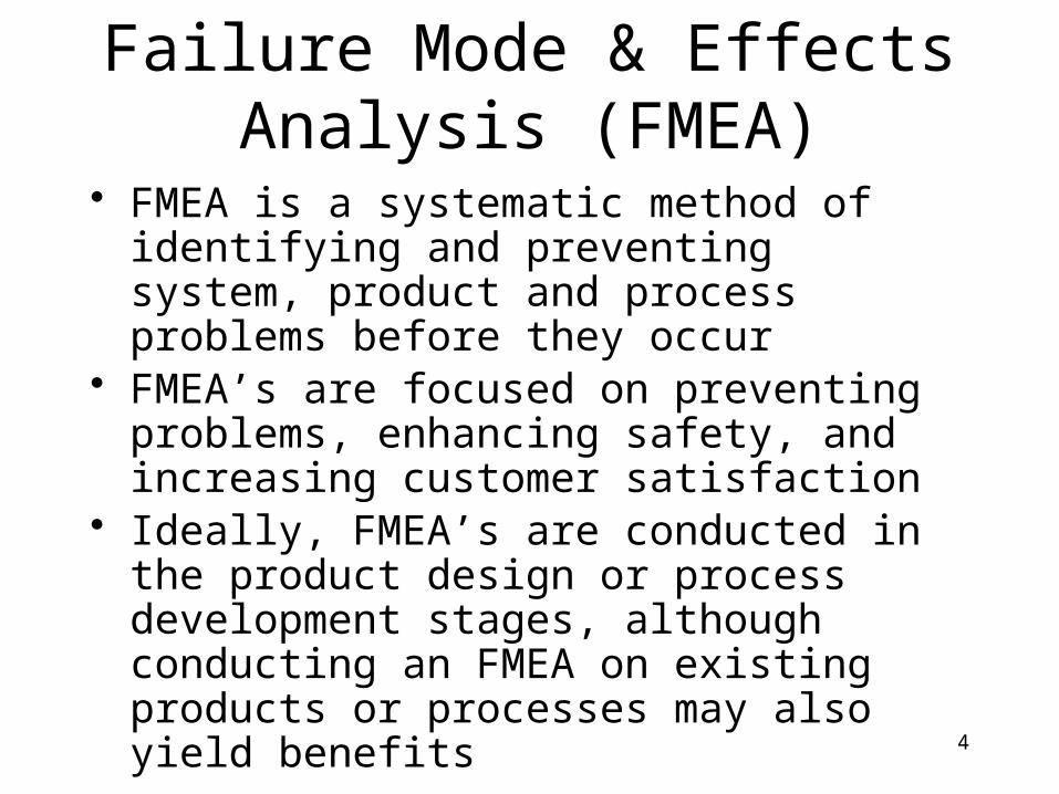
Failure Mode & Effects Analysis (FMEA)
• FMEA is a systematic method of identifying and preventing system, product and process problems before they occur
• FMEA’s are focused on preventing problems, enhancing safety, and increasing customer satisfaction
• Ideally, FMEA’s are conducted in the product design or process development stages, although conducting an FMEA on existing products or processes may also yield benefits

5
FMEA/FMECA History• The history of FMEA/FMECA goes back to the
early 1950s and 1960s.– U.S. Navy Bureau of Aeronautics, followed by the
Bureau of Naval Weapons:• Used “Failure Analysis” and “Failure Effect Analysis” to
establish reliability control over the design for flight control systems.
– National Aeronautics and Space Administration (NASA):
• Used FMECA to assure desired reliability of space systems.
• Department of Defense developed and revised the MIL-STD-1629A guidelines during the 1970s.– “Procedures for Performing a Failure Mode Effects
and Criticality Analysis” (1974, 1977, 1980).

6
FMEA/FMECA History (continued)
• Ford Motor Company published instruction manuals in the 1980s and the automotive industry collectively developed standards in the 1990s.– AIAG FMEA (1993, 1995, 2001) and SAE
J1739 ( 1994, 2000).
• Engineers in a variety of industries have adopted and adapted the tool over the years.– Aerospace, Automotive, Defense, Nuclear
Power, Semiconductor and other industries.

7
Published Guidelines• J1739 from the SAE for the automotive
industry.• AIAG FMEA-3 from the Automotive
Industry Action Group for the automotive industry.
• ARP5580 from the SAE for non-automotive applications.
• MIL-STD-1629A for FMECA (cancelled in
November, 1984).• IEC 812 from the International
Electrotechnical Commission.• BS 5760 from the BSI (British standard).

8
Other Guidelines• Other industry and company-specific
guidelines exist. For example:– EIA/JEP131 provides guidelines for the
electronics industry, from the JEDEC/EIA.
– P-302-720 provides guidelines for NASA’s GSFC spacecraft and instruments.
– SEMATECH 92020963A-ENG for the semiconductor equipment industry.
– Etc…
Introduction
9
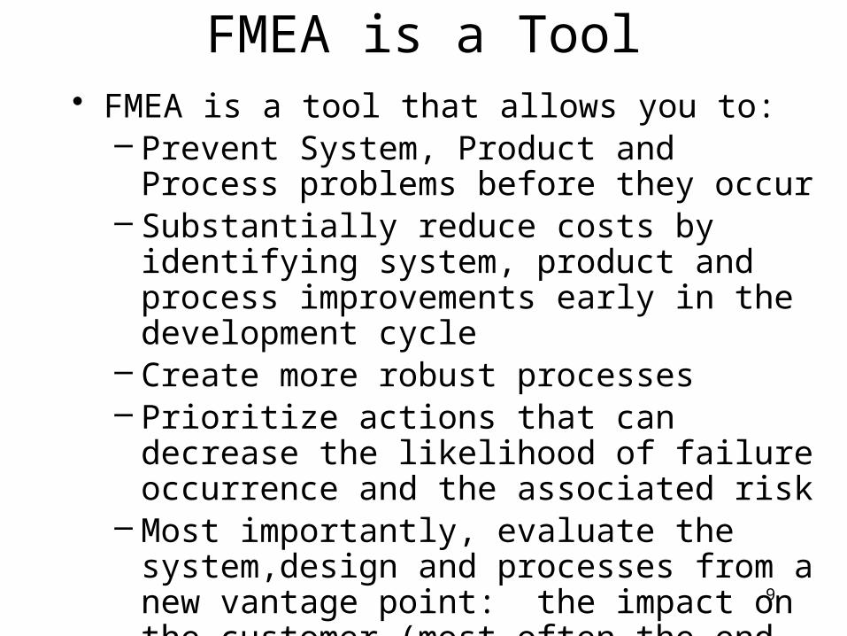
FMEA is a Tool• FMEA is a tool that allows you to:
– Prevent System, Product and Process problems before they occur
– Substantially reduce costs by identifying system, product and process improvements early in the development cycle
– Create more robust processes– Prioritize actions that can decrease the likelihood
of failure occurrence and the associated risk– Most importantly, evaluate the system,design and
processes from a new vantage point: the impact on the customer (most often the end user)

10
A Systematic Process
• FMEA provides a systematic process to: – Identify and evaluate potential failure modes– Identify potential causes of the failure mode– Identify and quantify the impact of potential failures
on customers by assigning numerical values based on ranking systems
– Identify and prioritize actions to reduce or eliminate the potential failure
– Implement an action plan based on assigned responsibilities and completion dates
– Document the associated activities
11
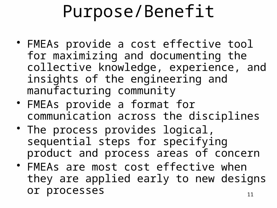
Purpose/Benefit
• FMEAs provide a cost effective tool for maximizing and documenting the collective knowledge, experience, and insights of the engineering and manufacturing community
• FMEAs provide a format for communication across the disciplines
• The process provides logical, sequential steps for specifying product and process areas of concern
• FMEAs are most cost effective when they are applied early to new designs or processes

12
Benefits of FMEA
• Contributes to improved designs for products and processes.– Higher reliability.– Better quality.– Increased safety.– Enhanced customer satisfaction.
• Contributes to cost savings.– Decreases development time and re-design costs.– Decreases warranty costs.– Decreases waste, non-value added operations.
• Contributes to the development of control plans, testing requirements, optimum maintenance plans, reliability growth analysis and related activities.
13
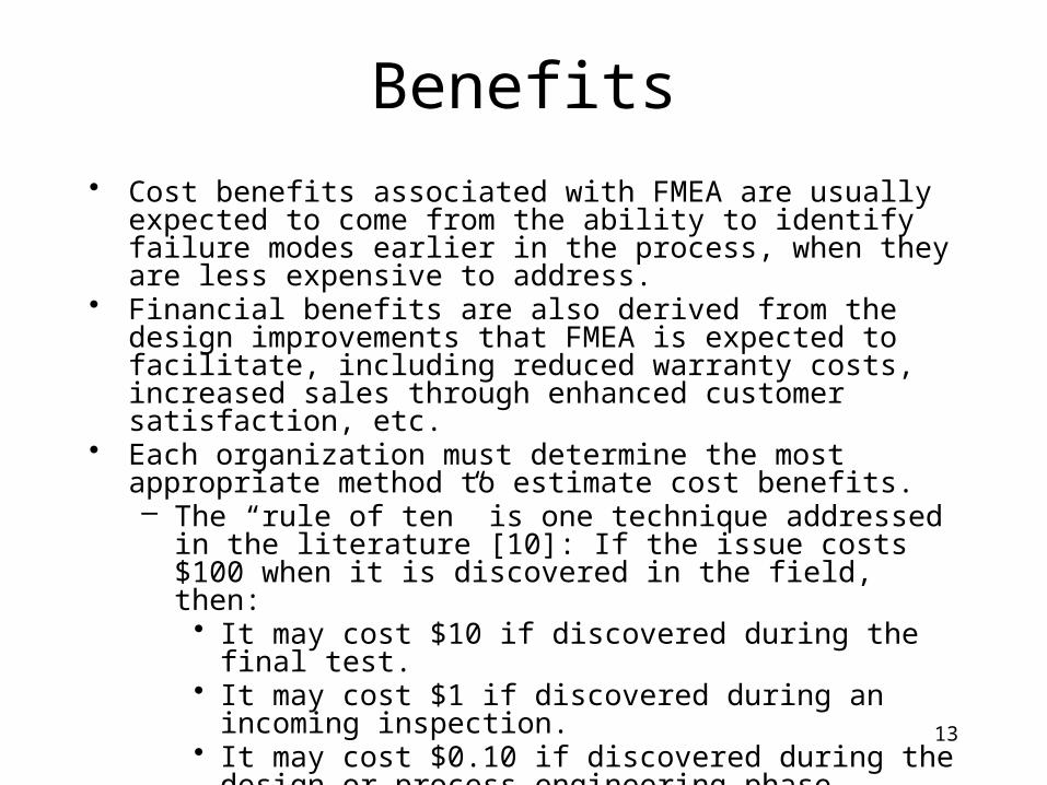
Benefits
• Cost benefits associated with FMEA are usually expected to come from the ability to identify failure modes earlier in the process, when they are less expensive to address.
• Financial benefits are also derived from the design improvements that FMEA is expected to facilitate, including reduced warranty costs, increased sales through enhanced customer satisfaction, etc.
• Each organization must determine the most appropriate method to estimate cost benefits.– The “rule of ten” is one technique addressed in the literature [10]:
If the issue costs $100 when it is discovered in the field, then:• It may cost $10 if discovered during the final test.• It may cost $1 if discovered during an incoming inspection.• It may cost $0.10 if discovered during the design or process
engineering phase.

14
FMEAs are Historical Records
FMEA’s:
• Communicate the logic of the engineers and the related design and process considerations
• Are indispensable resources for new engineers and future design and process decisions.
15
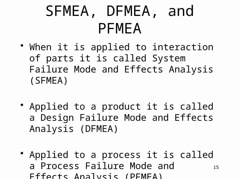
SFMEA, DFMEA, and PFMEA
• When it is applied to interaction of parts it is called System Failure Mode and Effects Analysis (SFMEA)
• Applied to a product it is called a Design Failure Mode and Effects Analysis (DFMEA)
• Applied to a process it is called a Process Failure Mode and Effects Analysis (PFMEA).
16
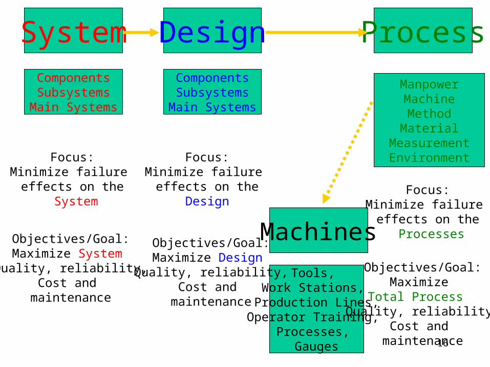
System Design ProcessComponentsSubsystems
Main Systems
ComponentsSubsystems
Main Systems
ManpowerMachineMethodMaterial
MeasurementEnvironment
Machines
Tools, Work Stations,
Production Lines,Operator Training,
Processes, Gauges
Focus:Minimize failure
effects on the System
Objectives/Goal:Maximize System Quality, reliability,
Cost and maintenance
Focus:Minimize failure
effects on theDesign
Objectives/Goal:Maximize Design Quality, reliability,
Cost and maintenance
Focus:Minimize failure
effects on the Processes
Objectives/Goal:Maximize
Total Process Quality, reliability,
Cost and maintenance
17
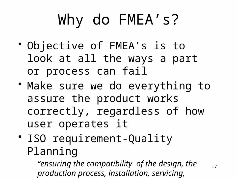
Why do FMEA’s?
• Objective of FMEA’s is to look at all the ways a part or process can fail
• Make sure we do everything to assure the product works correctly, regardless of how user operates it
• ISO requirement-Quality Planning– “ensuring the compatibility of the design, the
production process, installation, servicing, inspection and test procedures, and the applicable documentation”

18
What is the objective of FMEA?
• Uncover problems with the product that will result in safety hazards, product malfunctions, or shortened product life,etc..
• Ask ourselves “how the product will fail”?• How can we achieve our objective?
– Respectful communication– Make the best of our time, it’s limited; Agree
for ties to rank on side of caution as appropriate

19
Potential Applications for FMEA
• Component Proving Process• Outsourcing / Resourcing of product• Develop Suppliers to achieve Quality• Renaissance / Scorecard Targets• Major Process / Equipment / Technology• Changes• Justification of Fast Track RESA?• Cost Reductions• New Product / Design Analysis• Assist in analysis of a flat pareto chart

20
What tools are available to meet our objective?
• Benchmarking• customer warranty reports• design checklist or guidelines• field complaints• internal failure analysis• internal test standards• lessons learned• returned material reports• Expert knowledge

21
What are possible outcomes?
• actual failure modes• potential failure modes• customer and legal design requirements• duty cycle requirements• product functions• key product characteristics• Product Verification and Validation changes
efforts

22
How to FMEA…The Pre-Team Meeting
• Prior to assembling the entire team, it may be useful to arrange a meeting between two or three key engineers
• This could include persons responsible for design, quality, and testing.

23
How to FMEA.. (cont.)• The purpose of this meeting is to:
– Identify the system or component to be analyzed– Research sources of data including DFMEA
performed on similar products and gather pertinent data
– Determine whether relevant block diagrams exist or if they need to be created or updated
– Identify team members– Prepare an agenda and schedule for DFMEA
team activities– Identify item functions, failure modes and their
effects w/ smaller groups - saves time for whole group.
24
Block Diagram
• The FMEA should begin with a block diagram for the system or subsystem
• This diagram should indicate the functional relationship of the parts or components appropriate to the level of analysis being conducted.

25
Assumptions of DFMEA
• All systems/components are manufactured and assembled as specified by design
• Failure could, but will not necessarily, occur

26
Design FMEA Format
DetectPrevent
RPN
DET
OCC
SEV
ActionTaken
Action ResultsResponse &
TargetComplete
Date
RecommendedActions
RPN
Detec
CurrentDesignControls
Occur
PotentialCause(s)/
Mechanism(s)Of Failure
Class
Sev
PotentialEffect(s) of
Failure
Potential FailureMode
Item
DetectPrevent
RPN
DET
OCC
SEV
ActionTaken
Action ResultsResponse &
TargetComplete
Date
RecommendedActions
RPN
Detec
Current
Controls
Occur
PotentialCause(s)/
Mechanism(s)Of Failure
Class
Sev
PotentialEffect(s) of
Failure
Potential FailureMode
Function
27
General
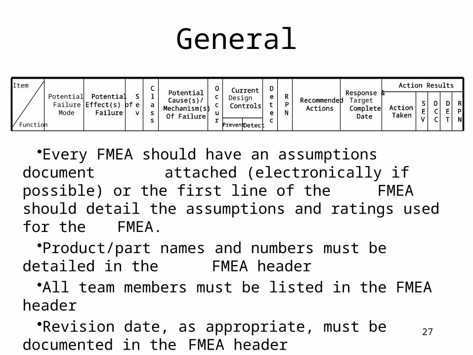
•Every FMEA should have an assumptions document attached (electronically if possible) or the first line of the
FMEA should detail the assumptions and ratings used for the FMEA.•Product/part names and numbers must be detailed in the
FMEA header•All team members must be listed in the FMEA header•Revision date, as appropriate, must be documented in the FMEA
header
DetectPrevent
RPN
DET
OCC
SEV
ActionTaken
Action ResultsResponse &
TargetComplete
Date
RecommendedActions
RPN
Detec
CurrentDesignControls
Occur
PotentialCause(s)/
Mechanism(s)Of Failure
Class
Sev
PotentialEffect(s) of
Failure
Potential FailureMode
Item
DetectPrevent
RPN
DET
OCC
SEV
ActionTaken
Action ResultsResponse &
CompleteDate
RecommendedActions
RPN
Detec
Current
Controls
Occur
PotentialCause(s)/
Mechanism(s)Of Failure
Class
Sev
PotentialEffect(s) of
Failure
Function
28
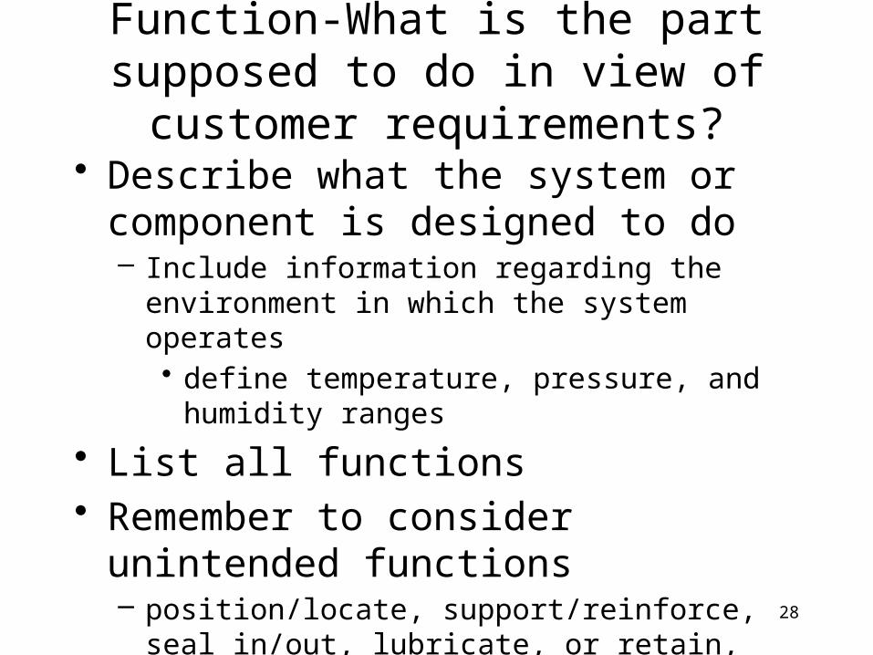
Function-What is the part supposed to do in view of customer requirements?
• Describe what the system or component is designed to do– Include information regarding the environment in
which the system operates• define temperature, pressure, and humidity ranges
• List all functions• Remember to consider unintended functions
– position/locate, support/reinforce, seal in/out, lubricate, or retain, latch secure

29
Function
•Function should be written in verb-noun context•Each function must have an associated measurable
•EXAMPLE:•HVAC system must defog windows and heat or cool cabin to 70 degrees in all operating conditions (-40 degrees to 100
degrees)•- within 3 to 5 minutes•or•- As specified in functional spec #_______; rev. date_________
DetectPrevent
RPN
DET
OCC
SEV
ActionTaken
Action ResultsResponse &
TargetComplete
Date
RecommendedActions
RPN
Detec
CurrentDesignControls
Occur
PotentialCause(s)/
Mechanism(s)Of Failure
Class
Sev
PotentialEffect(s) of
Failure
Potential FailureMode
Item
DetectPrevent
RPN
DET
OCC
SEV
ActionTaken
Action ResultsResponse &
CompleteDate
RecommendedActions
RPN
Detec
Current
Controls
Occur
PotentialCause(s)/
Mechanism(s)Of Failure
Class
Sev
PotentialEffect(s) of
Failure
Function
30
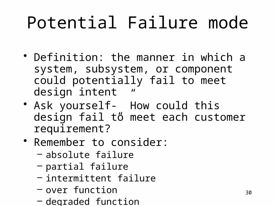
Potential Failure mode
• Definition: the manner in which a system, subsystem, or component could potentially fail to meet design intent
• Ask yourself- ”How could this design fail to meet each customer requirement?”
• Remember to consider:– absolute failure– partial failure– intermittent failure– over function– degraded function– unintended function
31
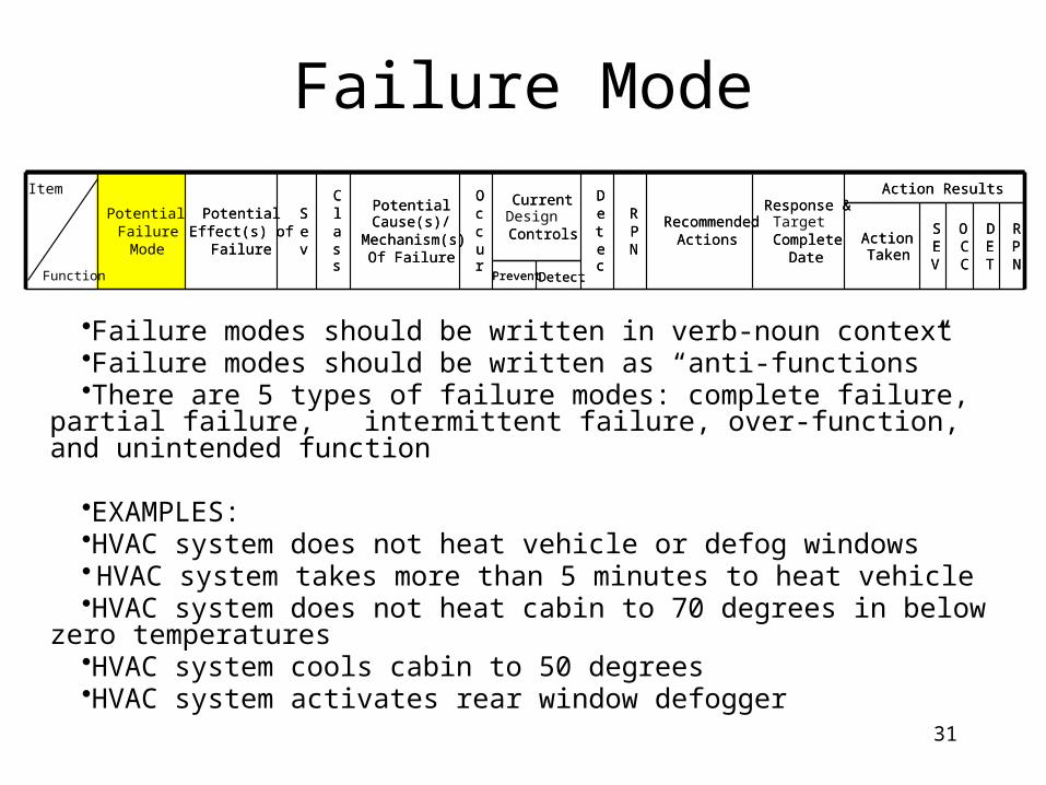
Failure Mode
•Failure modes should be written in verb-noun context•Failure modes should be written as “anti-functions”•There are 5 types of failure modes: complete failure, partial failure,
intermittent failure, over-function, and unintended function
•EXAMPLES:•HVAC system does not heat vehicle or defog windows• HVAC system takes more than 5 minutes to heat vehicle•HVAC system does not heat cabin to 70 degrees in below zero temperatures•HVAC system cools cabin to 50 degrees•HVAC system activates rear window defogger
DetectPrevent
RPN
DET
OCC
SEV
ActionTaken
Action ResultsResponse &
TargetComplete
Date
RecommendedActions
RPN
Detec
CurrentDesignControls
Occur
PotentialCause(s)/
Mechanism(s)Of Failure
Class
Sev
PotentialEffect(s) of
Failure
Potential FailureMode
Item
DetectPrevent
RPN
DET
OCC
SEV
ActionTaken
Action ResultsResponse &
CompleteDate
RecommendedActions
RPN
Detec
Current
Controls
Occur
PotentialCause(s)/
Mechanism(s)Of Failure
Class
Sev
PotentialEffect(s) of
Failure
Function

32
Consider Potential failure modes under:
• Operating Conditions– hot and cold– wet and dry– dusty and dirty
• Usage– Above average life cycle– Harsh environment– below average life cycle

33
Consider Potential failure modes under:
• Incorrect service operations– Can the wrong part be substituted inadvertently?– Can the part be serviced wrong? E.g. upside down,
backwards, end to end– Can the part be omitted?– Is the part difficult to assemble?
• Describe or record in physical or technical terms, not as symptoms noticeable by the customer.

34
Potential Effect(s) of Failure
• Definition: effects of the failure mode on the function as perceived by the customer
• Ask yourself- ”What would be the result of this failure?” or “If the failure occurs then what are the consequences”
• Describe the effects in terms of what the customer might experience or notice
• State clearly if the function could impact safety or noncompliance to regulations
• Identify all potential customers. The customer may be an internal customer, a distributor as well as an end user
• Describe in terms of product performance

35
Effect(s) of Failure
•Effects must be listed in a manner customer would describe them •Effects must include (as appropriate) safety / regulatory body, end user,
internal customers – manufacturing, assembly, service
•EXAMPLE:•Cannot see out of front window•Air conditioner makes cab too cold•Does not get warm enough•Takes too long to heat up
DetectPrevent
RPN
DET
OCC
SEV
ActionTaken
Action ResultsResponse &
TargetComplete
Date
RecommendedActions
RPN
Detec
CurrentDesignControls
Occur
PotentialCause(s)/
Mechanism(s)Of Failure
Class
Sev
PotentialEffect(s) of
Failure
Potential FailureMode
Item
DetectPrevent
RPN
DET
OCC
SEV
ActionTaken
Action ResultsResponse &
CompleteDate
RecommendedActions
RPN
Detec
Current
Controls
Occur
PotentialCause(s)/
Mechanism(s)Of Failure
Class
Sev
PotentialEffect(s) of
Failure
Function

36
Examples of Potential Effects
• Noise• loss of fluid• seizure of adjacent surfaces• loss of function• no/low output• loss of system
• Intermittent operations• rough surface• unpleasant odor• poor appearance • potential safety hazard• Customer dissatisfied

37
Severity
•Severity values should correspond with AIAG, SAE •If severity is based upon internally defined criteria or is based upon standard
with specification modifications, a reference to rating tables with explanation for use must be included in FMEA
•EXAMPLE:•Cannot see out of front window – severity 9•Air conditioner makes cab too cold – severity 5•Does not get warm enough – severity 5•Takes too long to heat up – severity 4
DetectPrevent
RPN
DET
OCC
SEV
ActionTaken
Action ResultsResponse &
TargetComplete
Date
RecommendedActions
RPN
Detec
CurrentDesignControls
Occur
PotentialCause(s)/
Mechanism(s)Of Failure
Class
Sev
PotentialEffect(s) of
Failure
Potential FailureMode
Item
DetectPrevent
RPN
DET
OCC
SEV
ActionTaken
Action ResultsResponse &
CompleteDate
RecommendedActions
RPN
Detec
Current
Controls
Occur
PotentialCause(s)/
Mechanism(s)Of Failure
Class
Sev
PotentialEffect(s) of
Failure
Function

38
Severity
• Definition: assessment of the seriousness of the effect(s) of the potential failure mode on the next component, subsystem, or customer if it occurs
• Severity applies to effects• For failure modes with multiple effects, rate
each effect and select the highest rating as severity for failure mode

39
Classification
•Classification should be used to define potential critical and significant characteristics
•Critical characteristics (9 or 10 in severity with 2 or more in occurrence-suggested) must have associated recommended actions
•Significant characteristics (4 thru 8 in severity with 4 or more in occurrence -suggested) should have associated recommended actions
•Classification should have defined criteria for application
•EXAMPLE:•Cannot see out of front window – severity 9 – incorrect vent location – occurrence
2•Air conditioner makes cab too cold – severity 5 - Incorrect routing of vent hoses
(too close to heat source) – occurrence 6
DetectPrevent
RPN
DET
OCC
SEV
ActionTaken
Action ResultsResponse &
TargetComplete
Date
RecommendedActions
RPN
Detec
CurrentDesignControls
Occur
PotentialCause(s)/
Mechanism(s)Of Failure
Class
Sev
PotentialEffect(s) of
Failure
Potential FailureMode
Item
DetectPrevent
RPN
DET
OCC
SEV
ActionTaken
Action ResultsResponse &
CompleteDate
RecommendedActions
RPN
Detec
Current
Controls
Occur
PotentialCause(s)/
Mechanism(s)Of Failure
Class
Sev
PotentialEffect(s) of
Failure
Function

40
Cause(s) of Failure
•Causes should be limited to design concerns•Analysis must stay within the defined scope (applicable system and interfaces to
adjacent systems) •Causes at component level analysis should be identified as part or system
characteristic (a feature that can be controlled at process)•There is usually more than one cause of failure for each failure mode•Causes must be identified for a failure mode, not an individual effect
•EXAMPLE:•Incorrect location of vents•Incorrect routing of vent hoses (too close to heat source)•Inadequate coolant capacity for application
DetectPrevent
RPN
DET
OCC
SEV
ActionTaken
Action ResultsResponse &
TargetComplete
Date
RecommendedActions
RPN
Detec
CurrentDesignControls
Occur
PotentialCause(s)/
Mechanism(s)Of Failure
Class
Sev
PotentialEffect(s) of
Failure
Potential FailureMode
Item
DetectPrevent
RPN
DET
OCC
SEV
ActionTaken
Action ResultsResponse &
CompleteDate
RecommendedActions
RPN
Detec
Current
Controls
Occur
PotentialCause(s)/
Mechanism(s)Of Failure
Class
PotentialEffect(s) of
Failure
Function
41
Potential Cause(s)/Mechanism(s) of failure
• Definition: an indication of a design weakness, the consequence of which is the failure mode
• Every conceivable failure cause or mechanism should be listed
• Each cause or mechanism should be listed as concisely and completely as possible so efforts can be aimed at pertinent causes

42
Potential Cause Mechanism• Tolerance build up• insufficient material• insufficient lubrication capacity• Vibration• Foreign Material• Interference• Incorrect Material thickness specified• exposed location• temperature expansion• inadequate diameter• Inadequate maintenance instruction• Over-stressing• Over-load• Imbalance• Inadequate tolerance
• Yield
• Fatigue
• Material instability
• Creep
• Wear
• Corrosion

43
Occurrence
•Occurrence values should correspond with AIAG, SAE •If occurrence values are based upon internally defined criteria, a reference must be included
in FMEA to rating table with explanation for use•Occurrence ratings for design FMEA are based upon the likelihood that a cause may occur,
based upon past failures, performance of similar systems in similar applications, or percent new content
•Occurrence values of 1 must have objective data to provide justification, data or source of data must be identified in Recommended Actions column
•EXAMPLE:•Incorrect location of vents – occurrence 3•Incorrect routing of vent hoses (too close to heat source) – occurrence 6•Inadequate coolant capacity for application – occurrence 2
DetectPrevent
RPN
DET
OCC
SEV
ActionTaken
Action ResultsResponse &
TargetComplete
Date
RecommendedActions
RPN
Detec
CurrentDesignControls
Occur
PotentialCause(s)/
Mechanism(s)Of Failure
Class
Sev
PotentialEffect(s) of
Failure
Potential FailureMode
Item
DetectPrevent
RPN
DET
OCC
SEV
ActionTaken
Action ResultsResponse &
CompleteDate
RecommendedActions
RPN
Detec
CurrentOccur
PotentialCause(s)/
Mechanism(s)Of Failure
Class
Sev
PotentialEffect(s) of
Failure
Function
44
Occurrence
• Definition: likelihood that a specific cause/mechanism will occur
• Be consistent when assigning occurrence• Removing or controlling the
cause/mechanism though a design change is only way to reduce the occurrence rating
45
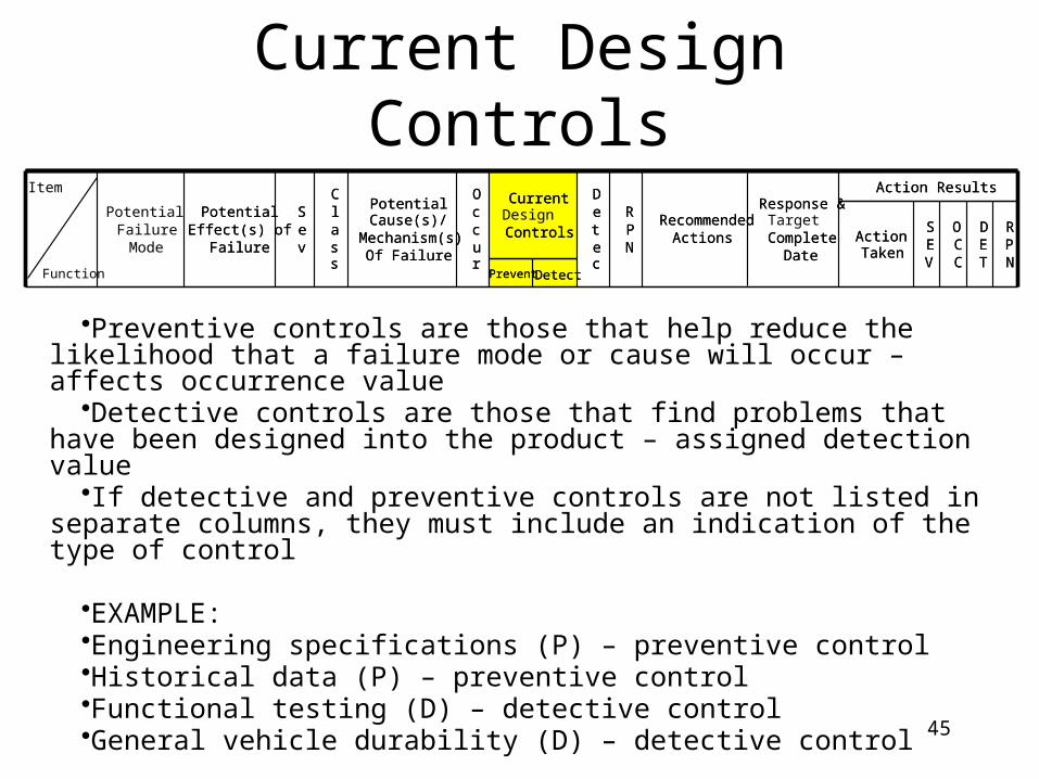
Current Design Controls
•Preventive controls are those that help reduce the likelihood that a failure mode or cause will occur – affects occurrence value
•Detective controls are those that find problems that have been designed into the product – assigned detection value
•If detective and preventive controls are not listed in separate columns, they must include an indication of the type of control
•EXAMPLE:•Engineering specifications (P) – preventive control•Historical data (P) – preventive control•Functional testing (D) – detective control•General vehicle durability (D) – detective control
DetectPrevent
RPN
DET
OCC
SEV
ActionTaken
Action ResultsResponse &
TargetComplete
Date
RecommendedActions
RPN
Detec
CurrentDesignControls
Occur
PotentialCause(s)/
Mechanism(s)Of Failure
Class
Sev
PotentialEffect(s) of
Failure
Potential FailureMode
Item
DetectPrevent
RPN
DET
OCC
SEV
ActionTaken
Action ResultsResponse &
CompleteDate
RecommendedActions
RPN
Detec
Current
Controls
Occur
PotentialCause(s)/
Mechanism(s)Of Failure
Class
Sev
PotentialEffect(s) of
Failure
Function
46
Current Design Controls• Definition: activities which will assure the design adequacy
for the failure cause/mechanism under consideration • Confidence Current Design Controls will detect cause and
subsequent failure mode prior to production, and/or will prevent the cause from occurring– If there are more than one control, rate each and select the lowest for
the detection rating• Control must be allocated in the plan to be listed, otherwise
it’s a recommended action • 3 types of Controls
– 1. Prevention from occurring or reduction of rate– 2. Detect cause mechanism and lead to corrective actions– 3. Detect the failure mode, leading to corrective actions

47
Examples of Controls
• Type 1 control– Warnings which alert product user to
impending failure– Fail/safe features– Design procedures/guidelines/ specifications
• Type 2 and 3 controls– Road test– Design Review– Environmental test– fleet test– lab test– field test– life cycle test– load test

48
Detection
•Detection values should correspond with AIAG, SAE •If detection values are based upon internally defined criteria, a reference
must be included in FMEA to rating table with explanation for use•Detection is the value assigned to each of the detective controls•Detection values of 1 must eliminate the potential for failures due to design
deficiency
•EXAMPLE:•Engineering specifications – no detection value•Historical data – no detection value•Functional testing – detection 3•General vehicle durability – detection 5
DetectPrevent
RPN
DET
OCC
SEV
ActionTaken
Action ResultsResponse &
TargetComplete
Date
RecommendedActions
RPN
Detec
CurrentDesignControls
Occur
PotentialCause(s)/
Mechanism(s)Of Failure
Class
Sev
PotentialEffect(s) of
Failure
Potential FailureMode
Item
DetectPrevent
RPN
DET
OCC
SEV
ActionTaken
Action ResultsResponse &
CompleteDate
RecommendedActions
RPN
Detec
Current
Controls
Occur
PotentialCause(s)/
Mechanism(s)Of Failure
Class
Sev
PotentialEffect(s) of
Failure
Function
49
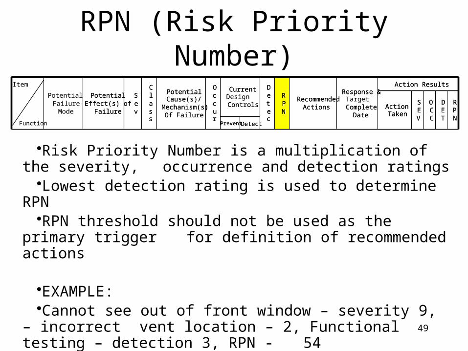
RPN (Risk Priority Number)
•Risk Priority Number is a multiplication of the severity, occurrence and detection ratings
•Lowest detection rating is used to determine RPN•RPN threshold should not be used as the primary trigger for
definition of recommended actions
•EXAMPLE:•Cannot see out of front window – severity 9, – incorrect vent
location – 2, Functional testing – detection 3, RPN - 54
DetectPrevent
RPN
DET
OCC
SEV
ActionTaken
Action ResultsResponse &
TargetComplete
Date
RecommendedActions
RPN
Detec
CurrentDesignControls
Occur
PotentialCause(s)/
Mechanism(s)Of Failure
Class
Sev
PotentialEffect(s) of
Failure
Potential FailureMode
Item
DetectPrevent
RPN
DET
OCC
SEV
ActionTaken
Action ResultsResponse &
CompleteDate
RecommendedActions
RPN
Detec
Current
Controls
Occur
PotentialCause(s)/
Mechanism(s)Of Failure
Class
Sev
PotentialEffect(s) of
Failure
Function

50
Risk Priority Number(RPN)
• Severity x Occurrence x Detection• RPN is used to prioritize concerns/actions• The greater the value of the RPN the greater the
concern• RPN ranges from 1-1000• The team must make efforts to reduce higher
RPNs through corrective action• General guideline is over 100 = recommended
action

51
Risk Priority Numbers (RPN's)• Severity
– Rates the severity of the potential effect of the failure.• Occurrence
– Rates the likelihood that the failure will occur.• Detection
– Rates the likelihood that the problem will be detected before it reaches the end-user/customer.
• RPN rating scales usually range from 1 to 5 or from 1 to 10, with the higher number representing the higher seriousness or risk.

52
RPN Considerations • Rating scale example:
– Severity = 10 indicates that the effect is very serious and is “worse” than Severity = 1.
– Occurrence = 10 indicates that the likelihood of occurrence is very high and is “worse” than Occurrence = 1.
– Detection = 10 indicates that the failure is not likely to be detected before it reaches the end user and is “worse” than Detection = 1.
1 5 10

53
RPN Considerations (continued)
• RPN ratings are relative to a particular analysis. – An RPN in one analysis is comparable to other
RPNs in the same analysis …– … but an RPN may NOT be comparable to
RPNs in another analysis.
1 5 10

54
RPN Considerations (continued)
• Because similar RPN's can result in several different ways (and represent different types of risk), analysts often look at the ratings in other ways, such as:– Occurrence/Severity Matrix (Severity and
Occurrence).– Individual ratings and various ranking tables.
1 5 10
55
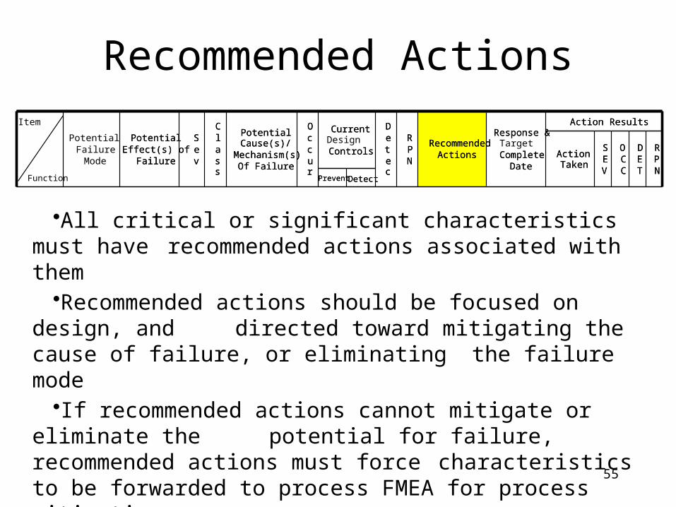
Recommended Actions
•All critical or significant characteristics must have recommended actions associated with them
•Recommended actions should be focused on design, and directed toward mitigating the cause of failure, or eliminating the failure mode
•If recommended actions cannot mitigate or eliminate the potential for failure, recommended actions must force characteristics to be forwarded to process FMEA for process mitigation
DetectPrevent
RPN
DET
OCC
SEV
ActionTaken
Action ResultsResponse &
TargetComplete
Date
RecommendedActions
RPN
Detec
CurrentDesignControls
Occur
PotentialCause(s)/
Mechanism(s)Of Failure
Class
Sev
PotentialEffect(s) of
Failure
Potential FailureMode
Item
DetectPrevent
RPN
DET
OCC
SEV
ActionTaken
Action ResultsResponse &
CompleteDate
RecommendedActions
RPN
Detec
Current
Controls
Occur
PotentialCause(s)/
Mechanism(s)Of Failure
Class
Sev
PotentialEffect(s) of
Failure
Function
56
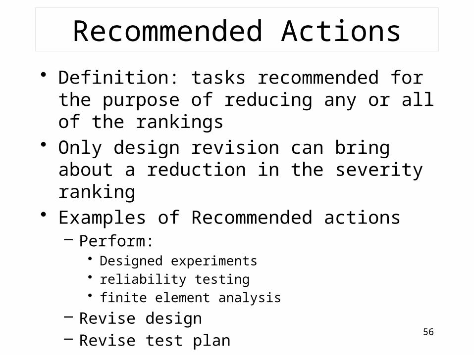
Recommended Actions• Definition: tasks recommended for the purpose of
reducing any or all of the rankings• Only design revision can bring about a reduction in
the severity ranking• Examples of Recommended actions
– Perform:• Designed experiments • reliability testing• finite element analysis
– Revise design– Revise test plan– Revise material specification

57
Responsibility & Target Completion Date
•All recommended actions must have a person assigned responsibility for completion of the action
•Responsibility should be a name, not a title•Person listed as responsible for an action must also be listed as a team member•There must be a completion date accompanying each recommended action
DetectPrevent
RPN
DET
OCC
SEV
ActionTaken
Action ResultsResponse &
TargetComplete
Date
RecommendedActions
RPN
Detec
CurrentDesignControls
Occur
PotentialCause(s)/
Mechanism(s)Of Failure
Class
Sev
PotentialEffect(s) of
Failure
Potential FailureMode
Item
DetectPrevent
RPN
DET
OCC
SEV
ActionTaken
Action ResultsResponse &
CompleteDate
RecommendedActions
RPN
Detec
Current
Controls
Occur
PotentialCause(s)/
Mechanism(s)Of Failure
Class
Sev
PotentialEffect(s) of
Failure
Function

58
Action Results
•Action taken must detail what actions occurred, and the results of those actions
•Actions must be completed by the target completion date•Unless the failure mode has been eliminated, severity should not
change•Occurrence may or may not be lowered based upon the results of
actions•Detection may or may not be lowered based upon the results of
actions•If severity, occurrence or detection ratings are not improved,
additional recommended actions must to be defined
DetectPrevent
RPN
DET
OCC
SEV
ActionTaken
Action ResultsResponse &
TargetComplete
Date
RecommendedActions
RPN
Detec
CurrentDesignControls
Occur
PotentialCause(s)/
Mechanism(s)Of Failure
Class
Sev
PotentialEffect(s) of
Failure
Potential FailureMode
Item
DetectPrevent
RPN
DET
OCC
SEV
ActionTaken
Action ResultsResponse &
CompleteDate
RecommendedActions
RPN
Detec
Current
Controls
Occur
PotentialCause(s)/
Mechanism(s)Of Failure
Class
Sev
PotentialEffect(s) of
Failure
Function

59
Exercise Design FMEA
• Perform A DFMEA on a pressure cooker

60

61
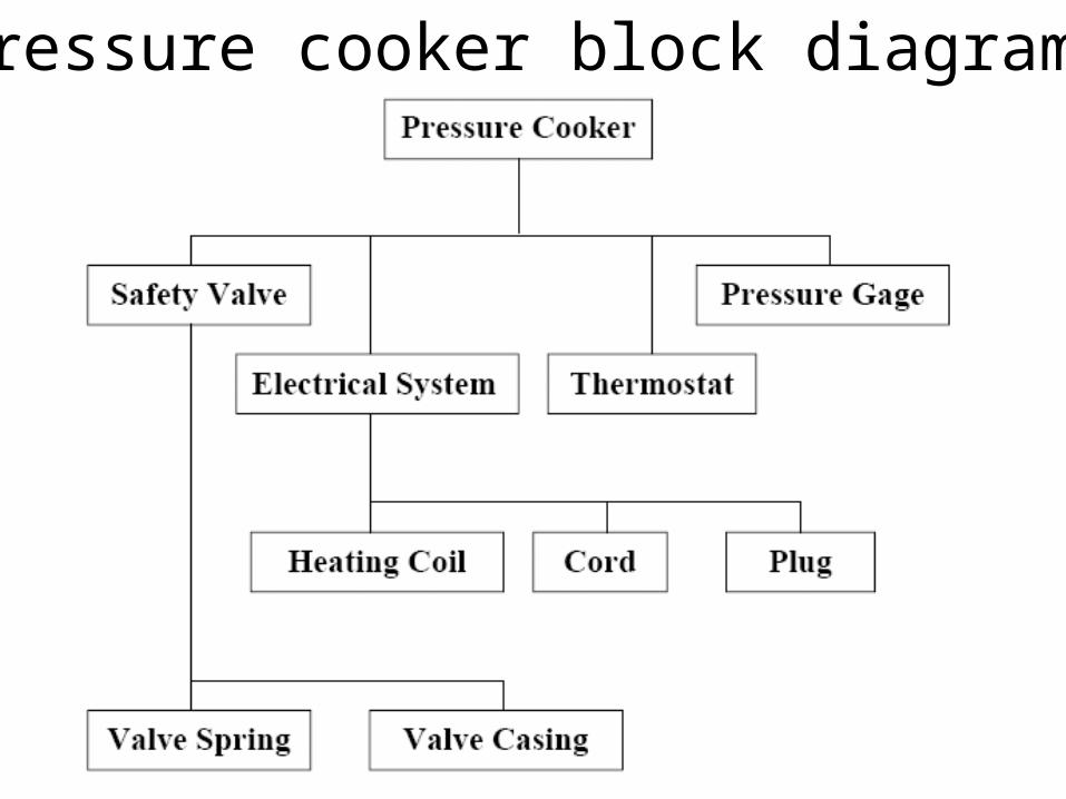
Pressure Cooker Safety Features
• 1. Safety valve relieves pressure before it reaches dangerous levels.
• 2. Thermostat opens circuit through heating coil when the temperature rises above 250° C.
• 3. Pressure gage is divided into green and red sections. "Danger" is indicated when the pointer is in the red section.
62
Pressure Cooker FMEA
• Define Scope:• 1. Resolution - The analysis will be
restricted to the four major subsystems (electrical system, safety valve, thermostat, and pressure gage).
• 2. Focus - Safety
63
Pressure cooker block diagram
64
Process FMEA
• Definition: – A documented analysis which begins with a
teams thoughts concerning requirements that could go wrong and ending with defined actions which should be implemented to help prevent and/or detect problems and their causes.
– A proactive tool to identify concerns with the sources of variation and then define and take corrective action.
65
PFMEA as a tool…
• To access risk or the likelihood of significant problem
• Trouble shoot problems• Guide improvement aid in determining
where to spend time and money• Capture learning to retain and share
knowledge and experience

66
Customer RequirementsDeign Specifications
Key Product CharacteristicsMachine Process Capability
Process Flow
DiagramProcess FMEA
Process Control
Plan
Operator Job
Instructions
Conforming ProductReduced Variation
Customer Satisfaction

67
Process Function Requirement
• Brief description of the manufacturing process or operation
• The PFMEA should follow the actual work process or sequence, same as the process flow diagram
• Begin with a verb

68
Inputs for PMEA
• Process flow diagram• Assembly instructions• Design FMEA• Current engineering drawings and specifications• Data from similar processes
– Scrap– Rework– Downtime– Warranty

69
Team Members for a PFMEA
• Process engineer• Manufacturing supervisor• Operators• Quality• Safety• Product engineer• Customers• Suppliers
70
PFMEA Assumptions
• The design is valid• All incoming product is to design
specifications• Failures can but will not necessarily occur• Design failures are not covered in a
PFMEA, they should have been part of the design FMEA

71
Potentional Failure Mode
• How the process or product may fail to meet design or quality requirements
• Many process steps or operations will have multiple failure modes
• Think about what has gone wrong from past experience and what could go wrong
72
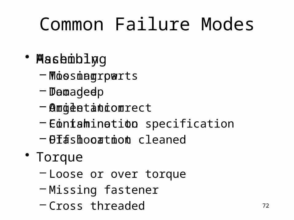
Common Failure Modes
• Assembly– Missing parts– Damaged– Orientation– Contamination– Off location
• Torque– Loose or over torque– Missing fastener– Cross threaded
• Machining– Too narrow– Too deep– Angle incorrect– Finish not to specification– Flash or not cleaned
73
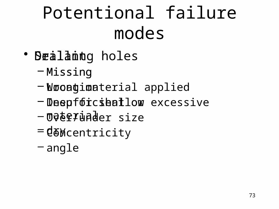
Potentional failure modes
• Sealant– Missing– Wrong material applied– Insufficient or excessive material– dry
• Drilling holes– Missing– Location– Deep or shallow– Over/under size– Concentricity– angle
74
Potential effects
• Think of what the customer will experience– End customer– Next user-consequences due to failure mode
• May have several effects but list them in same cell
• The worst case impact should be documented and rated in severity of effect

75
Potential Effects
• End user– Noise– Leakage– Odor– Poor appearance– Endangers safety– Loss of a primary function– performance
• Next operation– Cannot assemble– Cannot tap or bore– Cannot connect– Cannot fasten– Damages equipment– Does not fit– Does not match– Endangers operator
76
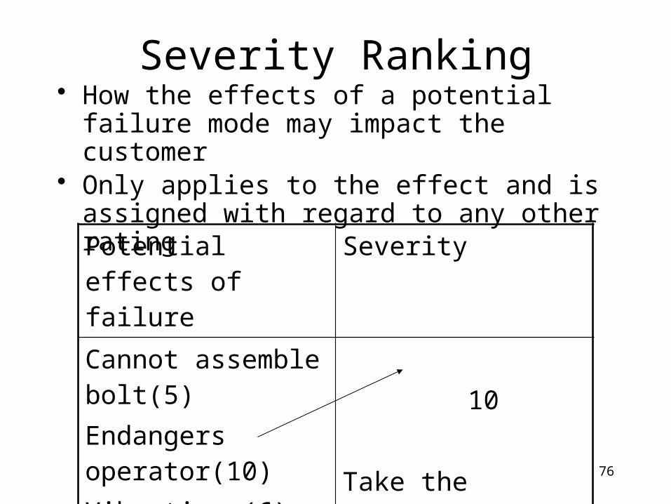
Severity Ranking• How the effects of a potential failure mode may
impact the customer• Only applies to the effect and is assigned with
regard to any other rating
Potential effects of failure
Severity
Cannot assemble bolt(5)Endangers operator(10)Vibration (6)
10
Take the highest effect ranking
77
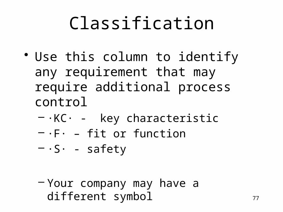
Classification
• Use this column to identify any requirement that may require additional process control– ∙KC∙ - key characteristic– ∙F∙ – fit or function– ∙S∙ - safety
– Your company may have a different symbol

78
Potential Causes
• Cause indicates all the things that may be responsible for a failure mode.
• Causes should items that can have action completed at the root cause level (controllable in the process)
• Every failure mode may have multiple causes which creates a new row on the FMEA
• Avoid using operator dependent statements i.e. “operator error” use the specific error such as “operator incorrectly located part” or “operator cross threaded part”

79
Potential Causes
• Equipment– Tool wear– Inadequate pressure– Worn locator– Broken tool– Gauging out of calibration– Inadequate fluid levels
• Operator– Improper torque– Selected wrong part– Incorrect tooling– Incorrect feed or speed rate– Mishandling– Assembled upside down– Assembled backwards

80
Occurrence Ranking
• How frequent the cause is likely to occur• Use other data available
– Past assembly processes– SPC– Warranty
• Each cause should be ranked according to the guideline
81
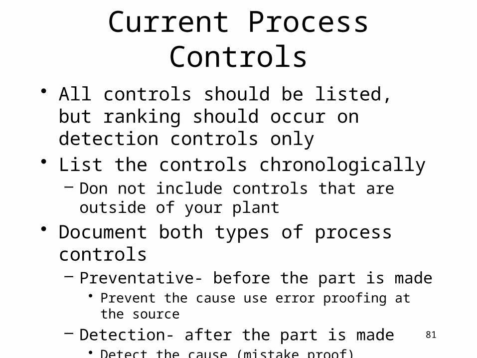
Current Process Controls
• All controls should be listed, but ranking should occur on detection controls only
• List the controls chronologically– Don not include controls that are outside of your plant
• Document both types of process controls– Preventative- before the part is made
• Prevent the cause use error proofing at the source
– Detection- after the part is made• Detect the cause (mistake proof)• Detect the failure mode by inspection

82
Process Controls
• Preventative– SPC– Inspection verification– Work instructions– Maintenance– Error proof by design– Method sheets– Set up verification– Operator training
• Detection– Functional test– Visual inspection– Touch for quality– Gauging– Final test
83
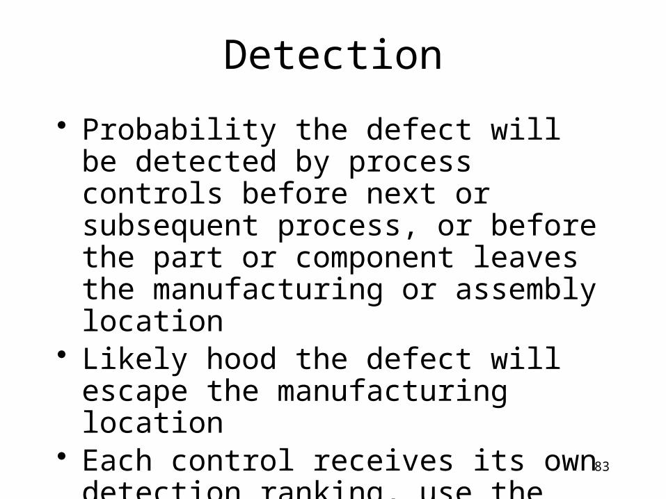
Detection
• Probability the defect will be detected by process controls before next or subsequent process, or before the part or component leaves the manufacturing or assembly location
• Likely hood the defect will escape the manufacturing location
• Each control receives its own detection ranking, use the lowest rating for detection

84
Risk Priority Number (RPN)
• RPN provides a method for a prioritizing process concerns
• High RPN’s warrant corrective actions• Despite of RPN, special consideration
should be given when severity is high especially in regards to safety

85
RPN as a measure of risk
• An RPN is like a medical diagnostic, predicting the health of the patient
• At times a persons temperature, blood pressure, or an EKG can indicate potential concerns which could have severe impacts or implications

86
Recommended actions
Control
Influence
Can’t control or influence at this time

87
Recommended Action
• Definition: tasks recommended for the purpose of reducing any or all of the rankings
• Examples of Recommended actions – Perform:
• Process instructions (P)• Training (P)• Can’t assemble at next station (D)• Visual Inspection (D)• Torque Audit (D)
88
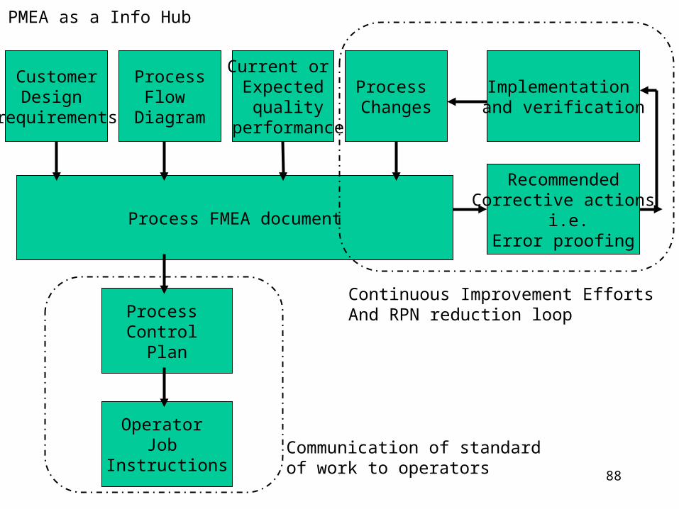
Process FMEA document
Process Control
Plan
Operator Job
Instructions
ProcessFlow
Diagram
Process Changes
Current or Expected quality
performance
CustomerDesign
requirements
Implementation and verification
RecommendedCorrective actions
i.e.Error proofing
Continuous Improvement EffortsAnd RPN reduction loop
Communication of standard of work to operators
PMEA as a Info Hub

89
FMEA process flow

90
Process FMEA exercise
• Task: Produce and mail sets of contribution requests for Breast Cancer research
• Outcome: Professional looking requests to support research for a cure, 50 sets of information, contribution request, and return envelope
91
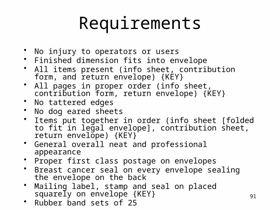
Requirements
• No injury to operators or users• Finished dimension fits into envelope• All items present (info sheet, contribution form, and return envelope)
{KEY}• All pages in proper order (info sheet, contribution form, return
envelope) {KEY}• No tattered edges• No dog eared sheets• Items put together in order (info sheet [folded to fit in legal envelope],
contribution sheet, return envelope) {KEY}• General overall neat and professional appearance• Proper first class postage on envelopes• Breast cancer seal on every envelope sealing the envelope on the back• Mailing label, stamp and seal on placed squarely on envelope {KEY}• Rubber band sets of 25

92
Process steps
• Fold information sheet to fit in legal envelope
• Collate so each group includes all components
• Stuff envelopes• Affix address, postage, and seal • Rubber bands sets of 25• Deliver to post office for mail today by 5
pm
94
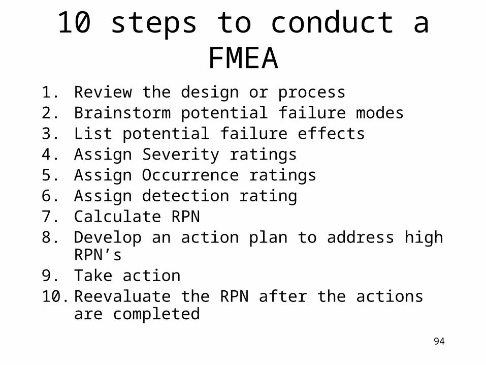
10 steps to conduct a FMEA
1. Review the design or process2. Brainstorm potential failure modes3. List potential failure effects4. Assign Severity ratings5. Assign Occurrence ratings6. Assign detection rating7. Calculate RPN 8. Develop an action plan to address high RPN’s9. Take action 10. Reevaluate the RPN after the actions are completed
95
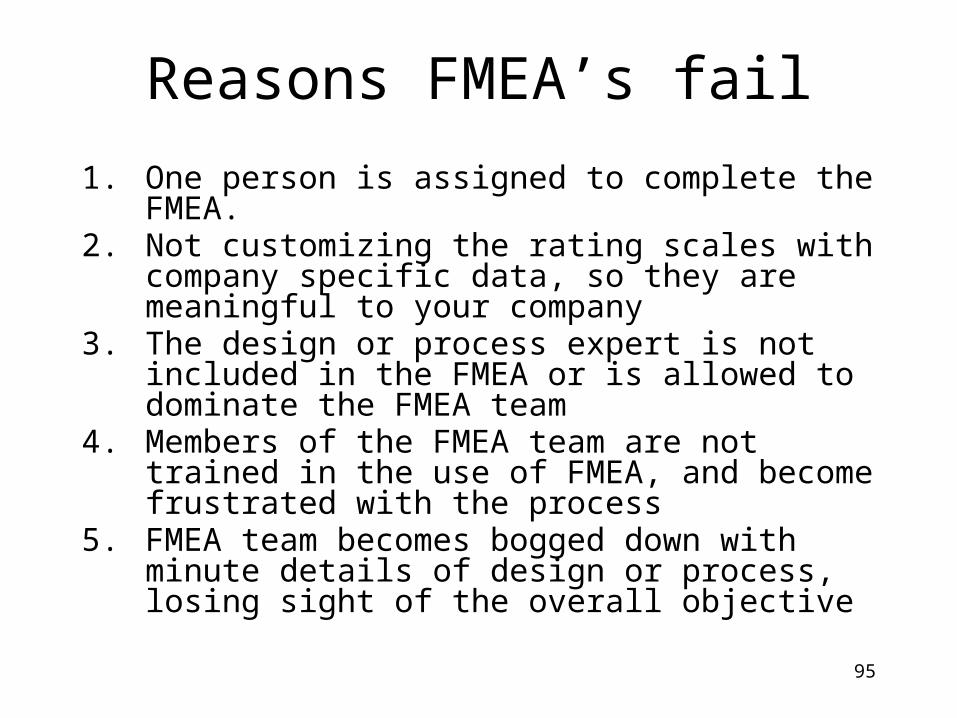
Reasons FMEA’s fail
1. One person is assigned to complete the FMEA.2. Not customizing the rating scales with company specific
data, so they are meaningful to your company3. The design or process expert is not included in the
FMEA or is allowed to dominate the FMEA team4. Members of the FMEA team are not trained in the use of
FMEA, and become frustrated with the process5. FMEA team becomes bogged down with minute details
of design or process, losing sight of the overall objective

96
Reasons FMEA’s fail
6. Rushing through identifying the failure modes to move onto the next step of the FMEA
7. Listing the same potential effect for every failure i.e. customer dissatisfied.
8. Stopping the FMEA process when the RPN’s are calculated and not continuing with the recommended actions.
9. Not reevaluating the high RPN’s after the corrective actions have been completed.
97
Software Recommendations
• Numerous types and specialized formats• Many have free trials
– X-FMEA Reliasoft– FMEA Pro-7– Access Data bases

98
Bibliography
• MIL-STD-1629A , Procedures for Performing a Failure Mode, Effects and Criticality Analysis, Nov. 1980.
• Sittsamer, Risk Based Error-Proofing, The Luminous Group, 2000
• MIL-STD-882B, 1984.• O’Conner, Practical Reliability Engineering, 3rd edition,
Revised, John Wiley & Sons,Chichester, England, 1996.• QS9000 FMEA reference manual (SAE J 1739)• McDerrmot, Mikulak, and Beauregard, The Basics of
FMEA, Productivity Inc., 1996.