f.m. f. - apem | homeapem-journal.org/archives/2016/apem11-4_287-298.pdf · cuniversity of...
TRANSCRIPT

287
AdvancesinProductionEngineering&Management ISSN1854‐6250
Volume11|Number4|December2016|pp287–298 Journalhome:apem‐journal.org
http://dx.doi.org/10.14743/apem2016.4.227 Originalscientificpaper
Finite element method for optimum design selection of carport structures under multiple load cases
Özkal, F.M.a,*, Cakir, F.b,c, Arkun, A.K.d aErzincan University, Department of Civil Engineering, Erzincan, Turkey bYıldız Technical University, Department of Architecture, İstanbul, Turkey cUniversity of California, Pacific Earthquake Engineering Research Center (PEER), Berkeley, California, USA dAmasya University, Department of Urban Design and Landscape Architecture, Amasya, Turkey
A B S T R A C T A R T I C L E I N F O
Inthefieldofstructuralmodelling,itisobviousthatthenumberofapplicabledesigns foraparticularstructuralnecessity is limitless.Alongwith the inte‐grationofvariouskindsofavailablestructuralmaterialsintothiscomplexity,itgetshardertobeable todeterminethebestdesignbeforetheproductionstage.Inrecentyears,withtheimprovementofcomputationalandstructuraltechnology, there have beenmany studies on the optimal design selection.This study focusesoncarport structuresandpursuing theirbestproducibleshape.Forthisaim,aperformanceindexformulationwasdevelopedtoassistthe decision ofmaterial efficiency as well as structural rigidity. Thereafter,five conceptualmodelswere numericallymodelled and finite element anal‐yses (FEA) formultiple load caseswere carried out. Reviewing the FEA re‐sults, themostappropriatemodelwasdeterminedbytheapplicationofthisperformancequalificationmethod.Resultsoftheanalysesshowthatoptimumdesignofstructuresundermultipleloadcasescanbedeterminedusingfiniteelementmethod.
©2016PEI,UniversityofMaribor.Allrightsreserved.
Keywords:StructuralproducibilityPerformancedecisionMultipleloadcasesManufacturingFiniteelementmethod
*Correspondingauthor:[email protected](Özkal,F.M.)
Articlehistory:Received26April2016Revised5October2016Accepted12October2016
1. Introduction
Structurescanbedesignedinmanydifferentwaystoprovidethestructuralrequirementssuchas performance, economy and appearance. The convenient design of structures is a very im‐portantfactorfortheirstructuralperformance.Shapeofthestructuresisaveryimportantfac‐tor for their structural behaviour. A poor designmight cause fault and quality problems in astructure.Itmayconducetodecreasequality,performanceandtoincreasecostandunnecessarymaterialusage.Therefore,structuraldesignisamajorconcerninengineeringstructures. Designobjectivesaregenerally imprecise real‐life situationsaswellas structuralproblemsandnaturalideaistodealdirectlywiththeseambiguousobjectives.Hence,businessexperienceshowsthatinmanycases,itisbeneficialtospecifythemcrispyandthensolvetheoptimizationproblem[1].Designofstructuresdependsonnotonlystructuralproblems,butalsoknowledgeand creativity of the designer. Therefore, design concepts can technically be discussed for astructureanddesignersseekthebestfeasibledesign.However,itisquitedifficulttodeterminewhichofthedesignsismoreefficientandbetterthantheotherones.Inrecentyears,withim‐provementsofcomputerandstructuraltechnology,oneofthewaystoachieveanefficientstruc‐turaldesignhasbeenmathematicaldesignoptimization.Maingoalofdesignoptimizationistodeterminethebestproducibledesignforastructureundervariousconstraints.Recently,design

Özkal, Cakir, Arkun
288 Advances in Production Engineering & Management 11(4) 2016
optimizationwith the finiteelementmethod(FEM)hasbecomemorepopularwithsignificantadvancesincomputertechnology.TodaymanydesignerandengineersappealtofiniteelementmethodandmanystructuralanalysissoftwarepackagesaresuitableforFEA.
Thedesignprocesscanbecategorizedinvariousways,butingeneral,itconsistsoffourmainphases[2].Thefirststageistodeterminethefunctionalityrequirementsandessentialparame‐ters;thesecondstageistodevelopconceptmodels;thethirdstageistoperformoptimizationonthedevelopedconceptmodelsandthelaststageistocomparetheoptimizationresultsandde‐cidethemostsuitabledesignbeforeproduction.Thegeneralflowdiagramofthestructuralde‐signprocess is shown inFig.1. In this study, thebestdesignof carport structureswasdeter‐minedbymeansofthesefoursteps.
Inpreviousstudies,manyresearchershaveinvestigatedthedesignprocessanddesignopti‐mizationofmanydifferent structures [3‐8]. In almostallof thepast studies,urbanstructureshavenotbeencompletely investigated.Therefore, thisstudy focusesonthecarportstructuresandtheirbestproducibledesign,sincetheyareoneofthemostcommonurbanstructures.Thestudy contributes to thebest designof carport structuresundermultiple load cases in that itdevelopsaperformanceindexformulation,revealstheimpactofmaterialefficiencyandstruc‐turalrigidityonthebestdesign.Moreover,thisstudyhelpstodeviseimplementstrategiesanddevelop actions to improve best design. It is also indicated that the effective optimumdesignselectioncontributestoimproveefficientstructuraldesign.
Fig.1Flowdiagramofthestructuraldesignprocess
2. Carport structures
Carportstructures,whicharealsoknownascarshelters,parkingshadesandparkingstructures,areopensidedstructuresthatusuallyconsistofaroofandloadbearingparts.Carportsarepop‐ular all around the world and they are widely used at houses, office buildings, public areas,shoppingmalls,retailoperationsandshoppingmalls.Carportsbringmanygreatbenefits,suchas preventing damage from hailstones, snow and rain, minimizing sun damage, protectingagainst poorer weather, moisture and corrosion. Carports, which can be freestanding or at‐tachedtoabuilding,mayhavearoofedorcanopiedformandsidesofcarportsareleftwhollyorpartiallyopen. Inotherwords, carportscanbedefinedasa semi‐openspace in thecontextofarchitectureorspacedesign. Theentranceofacarportisincontrasttoagenerallyopengarage.Acommonvariantoftheroofingisacorrugatedsheet,trapezoidalortheirtransparentformscorrugatedlightpanelsortrapezoidalplates.Opencarportswithoutaroofareusuallyusedasanopticalsettingofoutdoorspaces to emphasize this by surrounding open spaces. Increasingly, free areas of the roof arealsoused forsolarsystemsandasanextensivegreenroof.Agreenroofcancontribute tode‐creasetemperaturesandreducetheheatislandeffectintheurbanenvironment. Furthermore,usingcarports, lessmaterialsareneededandtheconstructiontimeisshorterthangarageconstruction.Carportsareassumedtobegreener.Moore[9]liststheadvantagesofcarportsasservingasacoveredmainentranceandaplacetoentertainanddooutdooractivi‐
Finite element method for optimum design selection of carport structures under multiple load cases
Advances in Production Engineering & Management 11(4) 2016 289
ties,inadditiontotheprovidingprotectionandstorageforthecars.Healsomentionsthatcar‐ports reduce complexity providing more than sufficient shelter, necessitate less constructionmaterials, and accommodate as aesthetically architectural design. Conclusively, he states thatpeopleconsidertheenvironmentalimpactofgaragescomparedtocarportsandchoosethecosteffectivecarportsduetotherisingenvironmentalconcerns.Theseseveraladvantagescontrib‐ute to widespread use of carports. On the other hand, carports offer no privacy, protectionagainsttheftorvandalism.Agarageismoresecurethanacarport.
2.1 Historical background of carport structures
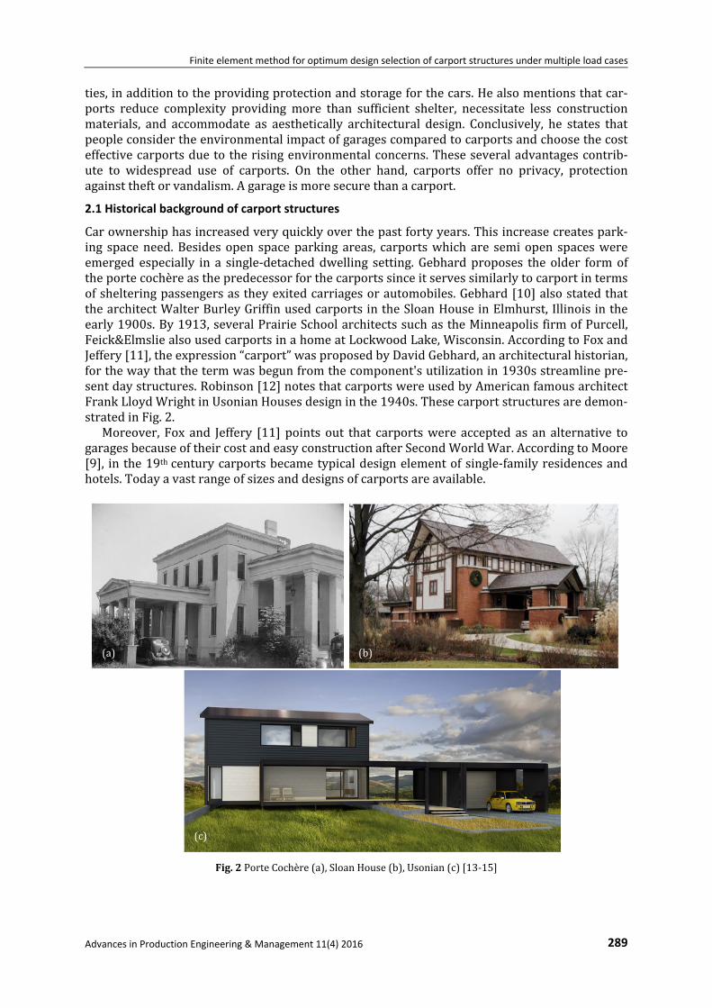
Carownershiphasincreasedveryquicklyoverthepastfortyyears.Thisincreasecreatespark‐ing spaceneed.Besidesopen spaceparking areas, carportswhichare semiopen spaceswereemerged especially in a single‐detacheddwelling setting.Gebhardproposes theolder formoftheportecochèreasthepredecessorforthecarportssinceitservessimilarlytocarportintermsofshelteringpassengersastheyexitedcarriagesorautomobiles.Gebhard[10]alsostatedthatthearchitectWalterBurleyGriffinusedcarportsintheSloanHouseinElmhurst,Illinoisintheearly1900s.By1913,severalPrairieSchoolarchitectssuchastheMinneapolisfirmofPurcell,Feick&ElmsliealsousedcarportsinahomeatLockwoodLake,Wisconsin.AccordingtoFoxandJeffery[11],theexpression“carport”wasproposedbyDavidGebhard,anarchitecturalhistorian,forthewaythatthetermwasbegunfromthecomponent'sutilizationin1930sstreamlinepre‐sentdaystructures.Robinson[12]notesthatcarportswereusedbyAmericanfamousarchitectFrankLloydWrightinUsonianHousesdesigninthe1940s.Thesecarportstructuresaredemon‐stratedinFig.2.
Moreover, Fox and Jeffery [11]points out that carportswere accepted as an alternative togaragesbecauseoftheircostandeasyconstructionafterSecondWorldWar.AccordingtoMoore[9], inthe19thcenturycarportsbecametypicaldesignelementofsingle‐familyresidencesandhotels.Todayavastrangeofsizesanddesignsofcarportsareavailable.
Fig.2PorteCochère(a),SloanHouse(b),Usonian(c)[13‐15]
(a) (b)
(c)

Özkal, Cakir, Arkun
290 Advances in Production Engineering & Management 11(4) 2016
2.2 Structural failures of carport structures
Carportstructuresareexposedtomanydifferentexternalandinternaleffectsthroughouttheirlives.Therefore,acarportstructureshouldbedesignedtowithstandstructuralloadingscenari‐os.Hence,theaccurateestimationoftheloadsandtheircombinationsonacarportmightbethemostimportantandthemostdifficulttaskfordesigners.Loadsoncarportstructuresarebasedondifferenttypesandforces,whicharedeadloads, live loadsandlateral loads.Carportstruc‐turesaddressthecarryingproblemsoftheseloads. Althoughcarportstructuresarehighlydurable,someofthemintheworldunfortunatelyaredeteriorated,damaged, collapsedor faileddue todifferenteffects. Ingeneral, thesestructuresaredestroyedandlosttheirqualitiesduetomanyreasonssuchasenvironmentalconditionsandnatural disasters. Therefore, it causes irreversible negative effects on the structure. Observedstructural failures occurs generally due to thematerial degradations and poor design. In thepast, severalcarportproblemsarosebecauseofpoordesign. Ifacarport isnotwelldesigned,successfully analysed and well‐constructed; it may face some problems like collapse, defor‐mation,fracture,fatigue,crackingorfailureoffixtures,fittingsorpartitionsanddiscomfortforoccupants.Manycarportstructuresareexposedtodestructiveverticalloadssuchasdeadloadandsnow loads,and these loadingscenarioscancausedamages to thecarports (Figs.3a,3b).Thistypeofdamageisverydangeroussinceitmaycausefatalanddestructivecrashesandfrac‐tures,alsocausesdiversifieddisplacementof thecarport components.Therefore,damageriskshouldbeconsideredandsomeprecautionsshouldbetakenagainstit.
Inadditiontoverticalloads,lateralloadssuchasearthquakeandwindloadsmayalsoaffectthecarports.Lateralloadsgenerallycausetothelateraldisplacementandirrevocabledamage.Windloadsleadtofailureofthecarportroofandaffectthestructuralstability(Fig.3c).Moreo‐ver, many carport structures are exposed to destructive earthquakes and these earthquakescausesomedamagestothestructure.Earthquakebaseddamagesoccurespeciallyontheverticalbearingcomponentsofthecarportsuchascrackinganddisintegrationofthestructure(Fig.3d).
Fig.3Structuralfailureofcarportstructuresduetosnowload–(a)and(b),windload(c),earthquake(d)[16‐19]
(a) (b)
(c) (d)

Finite element method for optimum design selection of carport structures under multiple load cases
Advances in Production Engineering & Management 11(4) 2016 291
3. Concept designs
Thesecondpartof thedesignprocess is todevelopconceptualmodels. In thisstage,designerselectstheinitialforms,typeofstructuresandmaterialsintermsofrequiredstructuralfunction.Successatthisstagedependsontheability,creativityandengineeringapproachofdesigners.
3.1 Material properties
Structural performance and behaviour of a structure technically depend on the constructionmaterials. Moreover, the cost, quality, and design of a structure vary by selected materials.Therefore,selectionoftheappropriatematerialtypeisacrucialandvitalprocessforengineer‐ingstructures.Today,thousandsofmaterialscanbeusedforthealltypesofstructures.Howev‐er,noteverymaterialmaybeacorrectchoiceforastructure;therefore,itisveryimportanttoselectsuitablematerials. Carportstructuresaregenerallymadeofsteel,wood,plasticandcomposites.Becauseofprov‐en properties and significant advantages, steel has been the dominatingmaterial for the loadbearingpartsofstructures.Moreover,polymersarewidelyusedfornon‐bearingpartsofstruc‐turesduetotheirlightweight,availability,easyusabilityandcorrosionresistance.Inthisstudy,load‐bearingpartsofthecarportsweredesignedasstructuralsteelandroofsaspolyethylene.MaterialspropertiescanbeobtainedfromANSYSlibrary[20],whicharesummarizedinTable1.
Table1Mechanicalpropertiesofthecarportmaterials
Structuralmaterials
Young’smodulus(MPa)
Bulkmodulus(MPa)
Shearmodulus(MPa)
Poisson’sratio
Density(kg/m3)
Structuralsteel 2E+5 1.67E+5 0.77E+5 0.30 7,850
Polyethylene 1,100 2,291 387 0.42 950
3.2 Conceptual models
Conceptualmodelsmean topreparealternativemodels fora structure. In thispart, designersdevelop variousmodels such as simple and complex shapes. This step is themost interactivesectionforthedesignandmainaimofdevelopingconceptualmodelsistoconsiderallpossibleoptions.Developedconceptualmodelsdependtotallyontheimagination,skillsandexperienceofthedesigners. Inthisstudy,fivedifferentconceptualmodelsweredevelopedanditwasconsideredtocovertheequalareaforallof them.Althoughthereis infinitenumberofotherpotentialmodelsandsomeofthemsurelyfitthepurposeevenbetter,thefactaboutoptimizationapproachesisthatitisneverpossible toachieve theglobaloptimum,but just the localoptimumresult.Sincemaingoalofthisstudyistoinvestigatethesuccessoffiniteelementmethodwhileconsideringspeci‐fiedstructuralcriteria,itispossibletoapplythecurrentdesignapproachoneverysortofdiffer‐entmodels.Moreover,severalsystems,whicharethemostpopularstylesofthecarportstruc‐tures,wereusedinthisstudy.Formodel‐1andmodel‐2,aslopingflatrooftypewasused.Ontheotherhand,aconcaverooftypewaspreferredformodel‐3,model‐4andmodel‐5.Thesetypesofroofsweredesigned in order to providemaximumvehicle coverage and aesthetic.DevelopedconceptualmodelsinthisstudyareshowninFig.4.
4. Numerical models
Numericalmodelsaremathematicalexpressionofastructuralmemberorsystemandtheyareused to determine the structural behaviour that might be subjected to multiple load cases.Therefore,numericalmodellingisabeneficiarymethodintermsofthemathematicalmodellingof thestructures.Numericalmodellingofstructuresgetseasierowingto the improvements incomputertechnologiesdaybyday.Inthescopeofthisstudy,conceptualmodelswerenumeri‐callymodelled using ANSYSWorkbench [20] software. Finite elementmodelwas constituted

Özkal, Cakir, Arkun
292 Advances in Production Engineering & Management 11(4) 2016
withSOLID186elements,whichhavequadratic20‐nodedhexahedrons/10‐nodedtetrahedrons,andthreedegreesoffreedompernode.Meshingwasgeneratedaccordingtothecomplexityofthe designs and adequate refinementwas applied on some of the regions,whichwere deter‐minedsubsequenttothepre‐andpost‐analysischecking.Thisiswhythenumberofnodesandelementsforsomeofthedesignsvary.Fig.5showsthenumericalmodelpropertiesofthecar‐portstructureswiththeillustrationofthemesheddesigns.
Plan Elevation 3DModel
Model–1
Steel Beams
Polyethylene Roof
Steel Beams
Steel Column
Steel Beam
Steel Tie Bar
Steel Column
Model–2
Steel Beams
Polyethylene Roof
Steel Beams
Polyethylene Roof
Steel Beams
Model–3
Steel Beams
Polyethylene Roof
Steel Beams
Steel Column
Polyethylene Roof
Steel Beams
Steel Column
Model–4
Polyethylene Roof
Steel Beams
Steel Column
Steel Beams
Model–5
Polyethylene Roof
Steel Column
Steel Column
Polyethylene Roof
Fig.4Conceptualcarportmodels
Model‐1 Model‐2 Model‐3 Model‐4 Model‐5
Elements 20016 21584 3724 7286 1684
Nodes 110963 58192 26332 21765 12943
NumericalModel
Fig.5Finiteelementparametersoftheconceptualmodels

Finite element method for optimum design selection of carport structures under multiple load cases
Advances in Production Engineering & Management 11(4) 2016 293
5. Finite element analysis
Material typeswereassigned to the structural componentsof the carport structures from theANSYSmaterial library.Thesematerialsarepolyethyleneandstructuralsteel for theroofandloadcarrierparts,respectively.Threetypesofanalyseswereperformedforeachofthemodels.One of them is themodal analysis that examines the structural behaviour for the firstmode,whiletheothersarestaticstructuralanalysesforsnowandwindloadings.Accordingtotheas‐sumptionsbasedoninternationalbuildingcodes,asnowloadof750Pawasappliedverticallyontheroof.Windloadwasappliedonlytotheroofbecauselateralloadingtothecarrierpartscouldbeneglectedowingtotheirinconsiderablesurfaceareas.Additionally,simplificationandroundingoffbutstillbasedontheinternationalcodeswerepreferredforthecalculationofwindloaddistributioninordertogeneralizetheloadingeffectforallofthestructuraldesigns.There‐fore,apositivepressureof400Patothebottomfacetandasuctionpressureof200Patothetopfacetoftheroofwereappliedinthenormaldirectionofsurfaceelements. With respect to thedeterminationof theoptimumdesignof conceptual carport structures,volumesoftheloadcarrierpartsandtotaldisplacementvaluesofthewholestructurewererec‐ordedandusedintheperformanceindexformulation.Moreover,itisdifficultandcomplicatedto provide analysis results for each node and element. Therefore, contour pictures and scaletableswereusedtopresenttheresults(Figs.6,7).Inthisstudy,multipleloadcaseswerecon‐sideredandtheFEAresultsarediscussedwithintheresultsanddiscussionssection.
Modal Snow Wind
Model–1
Model–2
Model–3
Model–4
Model–5
max min
Fig.6Totaldisplacementdistributionofthesteelbearingcomponents

Özkal, Cakir, Arkun
294 Advances in Production Engineering & Management 11(4) 2016
Modal Snow WindModel–1
Model–2
Model–3
Model–4
Model–5
max min
Fig.7Totaldisplacementdistributionoftheallstructuralcomponents
6. Determination of the optimum design
Astructuraldesignershouldconsider theeffectiveuseofmaterialsalongwith thesafety limitandestheticalsemblanceobjectives.Althoughthispointhasbeeninvestigatedindetailbysev‐eralresearchersoverthelastfewdecades,manufacturersgenerallyputthesemblanceforwardfor thepurposeof commercial concernsandpush the structuralperformanceof theirdesignsintobackground. Ifa technique issought inorder toanswerthequestion“Whichone is thebest?”,aperfor‐mancequalificationmethod isneeded tobeconstitutedsubsequent to thedefinitionofall thedesigncriterions[21]. Inthisstudy, fivetypesofpopularcarportdesignscoveringequalareaswereevaluated.Becauseexpectedconsumerbenefitequality isprovided forallof themodels,thereisnoneedtoconsiderthisfactor.Furthermore, itshouldbenotedthateachproduct, in‐cludingcarportstructures,mustbeoptimizednotonlybasedonmaterialconcernsorstructuralbehaviour,butalsobyconsideringtheeasy‐for‐manufactureandeasy‐for‐assemblyparadigms.Themost suitabledesign is usually a compromise among the abovementioned requirements.Becausecurrentstudydealswiththeroughdesignatthepre‐productionstage,ithasalsobeenneglectedfortheaimofobtainingoptimumresult.Forinstance,astabilityanalysisincorporat‐ingstructuralassemblydetailsthatwasstudiedbyManifold[22]orageotechnicalinvestigationthatwasstudiedbyHrestaketal.[23]couldbeintegratedasapost‐verificationstagetothede‐signprocessinordertomakesureeveryconstraintissatisfiedbeforetheproduction.

Finite element method for optimum design selection of carport structures under multiple load cases
Advances in Production Engineering & Management 11(4) 2016 295
Designobjectiveforacarportstructurecouldbesummarizedassatisfyingmaterialefficiencyobjectivewhilemaintainingarigidbehaviouragainstvariouspossibleloadcases.Althoughuni‐formstresslevelsforthewholestructurewillassistmaterialefficiency,sizeandshapedissimi‐larity of finite elements prevent an accurate calculation. Hence, a newmodified performanceindexformulation,basedgenerallyonthenodaldisplacement levels,shouldbebuiltaccordingtothefollowingproblemdefinition:
minimize ∑
subjectto ∗ ⇒ ∗
1
∗ ⇒ ∗ 1
where istheweightofthestructure, isthematerialdensity, isthevolumeoftheethele‐ment, isthetotalnumberofelements, istheabsolutevalueofthemaximumnodaldis‐placement, istheabsolutevalueoftheaveragenodaldisplacementvaluewhile ∗ and∗ aretheupperandlowerboundlimitsofthedisplacementconstraints,respectively. Forthedeterminationoftheoptimalityofcarportdesigns,aperformanceindex,whichcouldbeappliedinageneralscopeandconsidersalltheloadcases,shouldbedevelopedstepbystep.Inordertoconstitutearigidstructure,structuralperformancelevelbasedonthemaximumdis‐placementvalueoftheithmodelforthejthloadcaseisfirstlydefined.
∗
(1)
Secondly, theaveragenodaldisplacementvalueshouldbeaddedto the formulation for thepurposeofassistingmaterialefficiencyqualification.
∗
∗ (2)
Themathematicaldefinitionofstructuralperformancelevelisfinalizedbyimplementingtheweightvalueasfollows.
1 ∗
∗ (3)
However, there is a need to define a reference performance level in order to compare thedesignswitheachother.Consideringacertainnumberofmodelsareevaluatedinthisstudy,thisreferencelevelcouldbeformulatedasthemeanperformancelevelofallmodels.
1 1 ∗
∗ (4)
Finally, a performance index formulation is generatedby theproportionof the ithmodel’sandreferenceperformancelevelvalues.Itisnamedas becauseoftheaimtoattainarigiddesignwhileminimizingthematerialweightofthestructure;inotherwords,whilemaximizingthematerialefficiency.
1 ∑
1 ∑ 1 ∑
(5)
Özkal, Cakir, Arkun
296 Advances in Production Engineering & Management 11(4) 2016
Thisperformanceindexissuitabletobeusedforanytypeofdesignoptimizationorcompari‐sonprobleminordertodeterminetheoptimumstructurethatachievesarigidstructuralbehav‐iourwiththeefficientmaterialuseundermultiple loadcases.Optimumdesignselectioncouldbepracticedsimplybychoosingthemodelthathasthegreatestperformanceindex.
7. Results and discussions
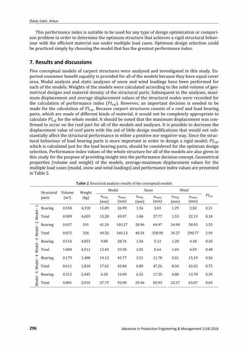
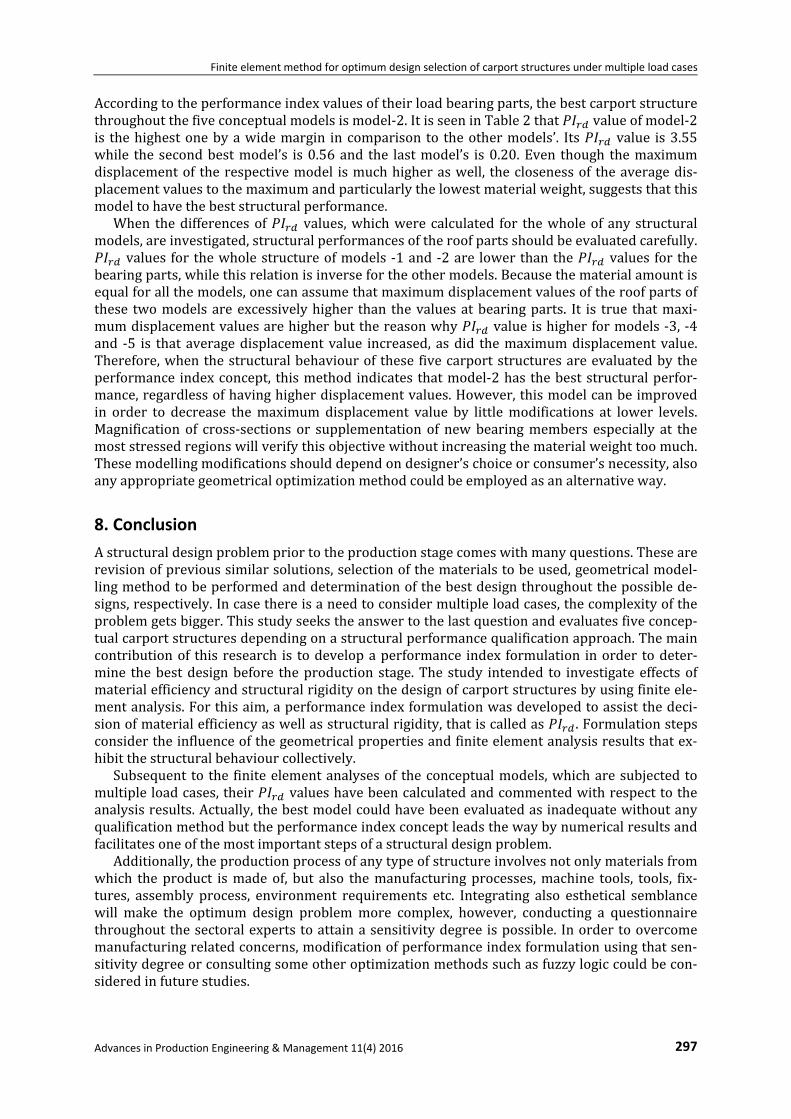
Fiveconceptualmodelsofcarportstructureswereanalysedandinvestigatedinthisstudy.Ex‐pectedconsumerbenefitequalityisprovidedforallofthemodelsbecausetheyhaveequalcoverarea.Modal analysis and static analyses of snow andwind loadings have been performed foreachofthemodels.Weightsofthemodelswerecalculatedaccordingtothesolidvolumeofgeo‐metricaldesignsandmaterialdensityofthestructuralparts.Subsequenttotheanalyses,maxi‐mumdisplacementandaveragedisplacementvaluesofthestructuralnodeswererecordedforthe calculation of performance index ( ). However, an important decision is needed to bemadeforthecalculationof .Becausecarportstructuresconsistofaroofand loadbearingparts,whicharemadeofdifferentkindsofmaterial,itwouldnotbecompletelyappropriatetocalculate forthewholemodel.Itshouldbenotedthatthemaximumdisplacementwascon‐firmedtooccurontheroofpartforallofthemodelsandanalyses.Itispossibletodecreasethedisplacementvalueofroofpartswiththeaidof littledesignmodificationsthatwouldnotsub‐stantiallyaffectthestructuralperformanceineitherapositivenornegativeway.Sincethestruc‐turalbehaviourof loadbearingpartsismoreimportantinordertodesignarigidmodel; ,whichiscalculatedjustfortheloadbearingparts,shouldbeconsideredfortheoptimumdesignselection.Performanceindexvaluesofthewholestructureforallofthemodelsarealsogiveninthisstudyforthepurposeofprovidinginsightintotheperformancedecisionconcept.Geometricalproperties (volume and weight) of the models, average‐maximum displacement values for themultipleloadcases(modal,snowandwindloadings)andperformanceindexvaluesarepresentedinTable2.
Table2Structuralanalysisresultsoftheconceptualmodels
Structuralparts
Volume(m3)
Weight(kg)
Modal Snow Wind
(mm)
(mm) (mm)
(mm)
(mm)
(mm)
Model‐1
Bearing 0.550 4,318 15.09 26.99 1.56 3.03 1.29 2.50 0.31
Total 0.909 4,659 15.28 49.97 1.86 27.77 1.53 22.13 0.18
Model‐2
Bearing 0.037 291 41.20 103.27 28.96 69.97 24.90 58.93 3.55
Total 0.075 326 44.56 160.13 40.54 358.99 34.27 290.77 2.94
Model‐3
Bearing 0.516 4,053 9.84 28.76 1.56 5.13 1.28 4.18 0.20
Total 1.000 4,512 12.43 29.30 2.05 5.64 1.69 4.59 0.48
Model‐4
Bearing 0.179 1,408 14.13 45.77 3.51 11.78 5.01 15.19 0.56
Total 0.611 1,818 17.62 45.84 6.89 47.26 8.34 42.63 0.75
Model‐5
Bearing 0.312 2,445 6.28 15.09 6.32 17.35 4.80 13.70 0.39
Total 0.801 2,910 27.75 92.90 29.36 82.93 22.57 63.07 0.65
Finite element method for optimum design selection of carport structures under multiple load cases
Advances in Production Engineering & Management 11(4) 2016 297
Accordingtotheperformanceindexvaluesoftheirloadbearingparts,thebestcarportstructurethroughoutthefiveconceptualmodelsismodel‐2.ItisseeninTable2that valueofmodel‐2is thehighestonebyawidemargin incomparison to theothermodels’. Its value is3.55while thesecondbestmodel’s is0.56and the lastmodel’s is0.20.Even though themaximumdisplacementof therespectivemodel ismuchhigheraswell, theclosenessof theaveragedis‐placementvaluestothemaximumandparticularlythelowestmaterialweight,suggeststhatthismodeltohavethebeststructuralperformance. When thedifferencesof values,whichwerecalculated for thewholeofanystructuralmodels,areinvestigated,structuralperformancesoftheroofpartsshouldbeevaluatedcarefully.
values forthewholestructureofmodels‐1and‐2are lowerthanthe values forthebearingparts,whilethisrelationisinversefortheothermodels.Becausethematerialamountisequalforallthemodels,onecanassumethatmaximumdisplacementvaluesoftheroofpartsofthese twomodelsareexcessivelyhigher than thevaluesatbearingparts. It is true thatmaxi‐mumdisplacementvaluesarehigherbutthereasonwhy valueishigherformodels‐3,‐4and ‐5 is thataveragedisplacementvalue increased, asdid themaximumdisplacementvalue.Therefore,whenthestructuralbehaviourof thesefivecarportstructuresareevaluatedbytheperformance indexconcept, thismethod indicates thatmodel‐2has thebeststructuralperfor‐mance,regardlessofhavinghigherdisplacementvalues.However,thismodelcanbeimprovedin order to decrease themaximum displacement value by littlemodifications at lower levels.Magnification of cross‐sections or supplementation of newbearingmembers especially at themoststressedregionswillverifythisobjectivewithoutincreasingthematerialweighttoomuch.Thesemodellingmodificationsshoulddependondesigner’schoiceorconsumer’snecessity,alsoanyappropriategeometricaloptimizationmethodcouldbeemployedasanalternativeway.
8. Conclusion
Astructuraldesignproblempriortotheproductionstagecomeswithmanyquestions.Thesearerevisionofprevioussimilarsolutions,selectionofthematerialstobeused,geometricalmodel‐lingmethodtobeperformedanddeterminationofthebestdesignthroughoutthepossiblede‐signs,respectively.Incasethereisaneedtoconsidermultipleloadcases,thecomplexityoftheproblemgetsbigger.Thisstudyseekstheanswertothelastquestionandevaluatesfiveconcep‐tualcarportstructuresdependingonastructuralperformancequalificationapproach.Themaincontributionof thisresearch is todevelopaperformance index formulation inorder todeter‐mine thebestdesignbefore theproduction stage.The study intended to investigate effectsofmaterialefficiencyandstructuralrigidityonthedesignofcarportstructuresbyusingfiniteele‐mentanalysis.Forthisaim,aperformanceindexformulationwasdevelopedtoassistthedeci‐sionofmaterialefficiencyaswellasstructuralrigidity,thatiscalledas .Formulationstepsconsidertheinfluenceofthegeometricalpropertiesandfiniteelementanalysisresultsthatex‐hibitthestructuralbehaviourcollectively. Subsequent to the finiteelementanalysesof theconceptualmodels,whicharesubjectedtomultipleloadcases,their valueshavebeencalculatedandcommentedwithrespecttotheanalysisresults.Actually,thebestmodelcouldhavebeenevaluatedasinadequatewithoutanyqualificationmethodbuttheperformanceindexconceptleadsthewaybynumericalresultsandfacilitatesoneofthemostimportantstepsofastructuraldesignproblem. Additionally,theproductionprocessofanytypeofstructureinvolvesnotonlymaterialsfromwhich theproduct ismadeof, but also themanufacturingprocesses,machine tools, tools, fix‐tures, assembly process, environment requirements etc. Integrating also esthetical semblancewill make the optimum design problemmore complex, however, conducting a questionnairethroughoutthesectoralexpertstoattainasensitivitydegreeispossible. Inordertoovercomemanufacturingrelatedconcerns,modificationofperformanceindexformulationusingthatsen‐sitivitydegreeorconsultingsomeotheroptimizationmethodssuchasfuzzylogiccouldbecon‐sideredinfuturestudies.

Özkal, Cakir, Arkun
References [1] Kosheleva, O., Kreinovich, V., Nguyen, H.T. (2015). Why it is important to precisiate goals. Departmental Tech-
nical Reports (CS), Technical Report: UTEP-CS-15-25, Paper 920. [2] Kirsch, U. (1981). Optimum structural design, McGraw Hill, New York, USA. [3] Cash, P., Hicks, B., Culley, S. (2015). Activity Theory as a means for multi-scale analysis of the engineering design
process: A protocol study of design in practice. Design Studies, Vol. 38, 1-32, doi: 10.1016/j.destud.2015.02.001. [4] Haldankar, M., Shirahatti, A.M. (2014). Finite element analysis and optimization of commercial bus body struc-
ture, International Journal of Engineering and Technical Research, Vol. 2, No. 12, 175-178. [5] Jain, R., Tandon, P., Kumar, M.V. (2014). Optimization methodology for beam gauges of the bus body for weight
reduction, Applied and Computational Mechanics, Vol. 8, No. 1, 47-62. [6] Srihari, P., Azad, D., Sreeramulu, D. (2014). Optimization of rail inserts using finite element analysis. Internation-
al Journal of Engineering, Science and Technology, Vol. 6, No. 2, 65-75, doi: 10.4314/ijest.v6i2.5. [7] Marczak, R.J. (2007). Optimization of elastic structures using boundary elements and a topological-shape sensi-
tivity formulation, Latin American Journal of Solids and Structures, Vol. 5, No. 2, 99-117. [8] Rajan, S.D., Belegundu, A.D., Lee, D., Damle, A.S., St Ville, J. (2004). Finite element analysis & design optimization
in a distributed computing environment, In: Collection of Technical Papers – 10th AIAA/ISSMO Multidisciplinary Analysis and Optimization Conference, Albany, NY, USA, Vol. 3, 1716-1726.
[9] Moore, A. Carport History, from https://www.versatube.com/news/carport-history, accessed January 30, 2016. [10] Gebhard, D. (1992). The suburban house and the automobile, In: Wachs, M., Crawford, M. (ed.), The car and the
city: the automobile, the built environment and daily urban life, Ann Arbor, University of Michigan Press, Michi-gan, USA, 106-123.
[11] Fox, J., Jeffery, R.B. (2005). Carport Integrity Policy, Arizona State Historic Preservation Office, Preservation Stud-ies, University of Arizona, USA, 1-9.
[12] Robinson, M. (2000). Taj Mahal on a Cul de Sac: Concrete blocks, carports and architectural appropriation, Arris – The Journal of the Southeast Chapter of the Society of Architectural Historians, Vol. 11, 71-83.
[13] Anonymous. Vintage Designs, Gaineswood, from http://vintagedesigns.com/architecture/gkrev/gwd/index.htm, accessed January 29, 2016.
[14] Anonymous. Auto Space, The Garage Journal, from http://www.garagejournal.com/2009/03/auto-space, accessed January 29, 2016.
[15] Anonymous. Affordable, Modern, Sustainable Homes, http://www.archdaily.com/238195/connecthomes-offers-affordable-modern-sustainable-homes/4series_carport, accessed January 29, 2016.
[16] Anonymous. Carport Collapse (Spokane), from http://images.fanpop.com/images/image_uploads/Winter-in-the-Inland-Northwest-winter-708370_450_299.jpg, accessed January 21, 2016.
[17] Anonymous. Imgarcade, Homemade Carport Collapse, from http://imgarcade.com/1/homemade-carport, ac-cessed January 21, 2016.
[18] Stickney, R., NBC San Diego, Collapsed Carport Crushes Cars in Alpine, from http://www.nbcsandiego.com/news/local/Carport-Collapse-Alpine-Arnold-Way-San-Diego-Heartland--234238281.html, accessed January 21, 2016.
[19] Anonymous. Oxu.az, A powerful earthquake in California: There's destruction, from http://ru.oxu.az/world/ 39156, accessed January 21, 2016.
[20] ANSYS (2014). Releases 14.0, Finite element analysis software, USA. [21] Özkal, F.M., Uysal, H. (2012). A fully stressed design method to determine the optimum strut-and-tie model for
beam-column connections. International Journal of Computational Methods, Vol. 9, No. 3, 1250035, doi: 10.1142/S0219876212500351.
[22] Manifold, S.M. (2014). Stability analysis and finite element stress analysis of a solarwing carport structure and solar panel array, Technical Report: Concurrent Design, Inc., from http://www.concurrentdesign.com/engineering-analysis.htm, accessed September 28, 2016.
[23] Hrestak, T., Lazarević, A.J., Frgić, L. (2015). Stress and strain analysis during the Sleme tunnel excavation, Tech-nical Gazette – Tehnički Vjesnik, Vol. 22, No. 3, 703-709, doi: 10.17559/TV-20140530103847.
298 Advances in Production Engineering & Management 11(4) 2016