fm 6-40/mcwp 3-1 - asktop.netasktop.net/wp/download/21/fm_6-40c1.pdffm 6-40/mcwp 3-16.4, april 1996,...
TRANSCRIPT

C1, FM 6-40/MCWP 3-1.6.19
Change HEADQUARTERSNo.1 DEPARTMENT OF THE ARMY
Washington, DC, 1 October 1999
Tactics, Techniques, and Procedures forFIELD ARTILLERY
MANUAL CANNON GUNNERY
FM 6-40/MCWP 3-16.4, April 1996, is changed as follows:
1. Change the following paragraphs or sections (changes are in bold type):
Replace Paragraph 6-1, Page 6-1 with the following:
6-1. Description
A firing chart is a graphic representation of a portion of the earth's surface used for determiningdistance (or range) and direction (azimuth or deflection). The chart may be constructed by using amap, a photomap, a gridsheet, or other material on which the relative locations of batteries, knownpoints, targets, and observers can be plotted. Additional positions, fire support coordinating measures,and other data needed for the safe and accurate conduct of fire may also be recorded.
Replace Step 5, Table 6-6, Page 6-19 with the following:
5 Place a plotting pin opposite the number on the azimuth scale (blue numbers) on the arc of theRDP corresponding to the last three digits of the azimuth in which the arm of the RDP isoriented. The location of the pin represents a temporary index and will not be replaced with apermanent index. The value of the pin is the value of the first digit of the azimuth in which thearm o f the RDP is oriented. Use the rules outlined in step 4 of Table 6-5 to determine wherethe pin should be placed. In Figure 6-15, the azimuth of lay is 1850, so the RDP has beenoriented east (1600 mils).
Replace Figure 7-1, Page 7-1 with the following:
STANDARD CONDITIONSWEATHER
1 AIR TEMPERATURE 100 PERCENT (59° F)2 AIR DENSITY 100 PERCENT (1,225 gm/m3)3 NO WIND
POSITION1 GUN, TARGET AND MDP AT SAME ALTITUDE2 ACCURATE RANGE3 NO ROTATION OF THE EARTH
MATERIAL1 STANDARD WEAPON, PROJECTILE, AND FUZE2 PROPELLANT TEMPERATURE (70° F)3 LEVEL TRUNNIONS AND PRECISION SETTINGS4 FIRING TABLE MUZZLE VELOCITY5 NO DRIFT
LEGEND: gm/m3 - grams per cubic meter

Replace Table C-6, page C-18, with the following
Table C-6. Target Acquisition Method.
TLE = 0 Meters (CEP) TLE = 75 Meters (CEP) TLE = 150 Meters (CEP) TLE = 250 Meters (CEP)Forward observer with laserTarget area basePhotointerpretationAirborne target location
Counterbattery RadarAirborne infrared systemFlash rangingCountermortar radar
Sound ranging Forward observer w/o laserAir observerTactical airForward observer (non FA)Long-range patrolSide-looking airborne radarCommunications intelShell reports
2. Remove old pages and insert new pages indicated below:
REMOVE PAGES INSERT PAGES
8-16 8-16
15-7 TO 15-25 15-7 TO 15-45 (Including Figure 15-22
on page 15-26)
3. Insert new pages as indicated below:
INSERT PAGES
13-77 to 13-82
4. File this transmittal sheet in the front of the publication for reference.
DISTRIBUTION RESTRICTION: Approved for public release; distribution is unlimited.

FM 6-40MCWP 3-16.4
1 October 1999
By Order of the Secretary of the Army:
Official:
By Direction of the Commandant of the Marine Corps:
DISTRIBUTION:
Active Army, Army National Guard, and U.S. Army Reserve: To be distributed in accordance with initialdistribution number 110044, requirements for FM 6-40/MCWP 3-16.4.
JOEL B. HUDSONAdministrative Assistant to the
Secretary of the Army 0011015
ERIK K. SHINSEKIGeneral, United States Army
Chief of Staff
J. E. RHODESLieutenant General, US Marine Corps
Commanding GeneralMarine Corps Combat Development Command

FM 6-40 ______________________________________________________________________
8-15. Determination of 10-Mil Site Factor Without a High-Angle GFT
The 10-mil site factor is the value of high angle site for every 10 mils of angleof site. The 10-mil site factor can be determined manually by solving two equalequations for the 10-mil site factor.
SI = < SI + CAS (FOR LOW AND HIGH ANGLE)SI = < SI + ( | < SI | X CSF)
FOR POSITIVE ANGLES OF SITE:
HIGH ANGLE SITE = < SI ( 1 + CSF )
FOR NEGATIVE ANGLES OF SITE:
HIGH ANGLE SITE = < SI ( 1 - CSF )
USING THE HIGH ANGLE GFT:
HIGH ANGLE SITE = (< SI / 10) X 10-MIL SI FACTOR
HOW TO DETERMINE 10-MIL SI FACTOR WITHOUT A GFT:
FOR POSITIVE ANGLES OF SITE: 10-MIL SI FACTOR = 10 ( 1 + CSF )FOR NEGATIVE ANGLES OF SITE: 10-MIL SI FACTOR = 10 ( 1 - CSF )
NOTE: If the 10-mil site factor is not listed on the high angle GFT, use the last listed value or changecharges
The FDC can compute high angle site by manually determining the 10-mil site factorfor those situations when a high angle GFT is not available. The 10-mil site factorfrom the GFT actually reflects the complementary angle of site for a positive VI.Therefore, this method will introduce a slight inaccuracy when estimating for negativeVI's
8-16
______________________________________________Chg 1 FM 6-40/MCWP 3-16.4
13-77
13-42. Sense And Destroy Armor (SADARM M898)
The M898 SADARM projectile is a base ejecting munition carrying a payload oftwo target sensing submunitions. The projectile is a member of the DPICM family, and isballistically similar to the M483A1. The technical fire direction computations are similar tothose used for the ADAM projectile, in that low level wind corrections must be applied to thefiring solution (because of the high Height of Burst) in order to place the payload at the optimallocation over the target area.
13-43. M898 Firing Data Computations
Firing data are computed for SADARM by using the FT 155 ADD-W-0 or FT 155 ADD-W-1 in conjunction with the FT 155 AN-2. The difference between the ADD-W-0 and ADD-W-1 is the Height of Burst of the projectile. The ADD-W-1 increases the HOB to correct forchanges in the operational parameters of the projectile. The ADD-W-1 is the preferred methodof producing data, although the ADD-W-0 procedure may be used in lieu of the FT ADD 155-W-1 if it is unavailable. (Note: BCS Version 11 will incorporate the ADD-W-1 solution. BCSVersion 10 has the incorrect HOB, and automated firings must also incorporate the change inHOB discussed in the ADD-W-0 method).
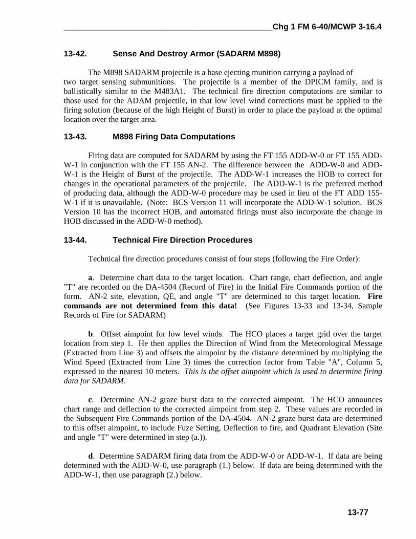
13-44. Technical Fire Direction Procedures
Technical fire direction procedures consist of four steps (following the Fire Order):
a. Determine chart data to the target location. Chart range, chart deflection, and angle"T" are recorded on the DA-4504 (Record of Fire) in the Initial Fire Commands portion of theform. AN-2 site, elevation, QE, and angle "T" are determined to this target location. Firecommands are not determined from this data! (See Figures 13-33 and 13-34, SampleRecords of Fire for SADARM)
b. Offset aimpoint for low level winds. The HCO places a target grid over the targetlocation from step 1. He then applies the Direction of Wind from the Meteorological Message(Extracted from Line 3) and offsets the aimpoint by the distance determined by multiplying theWind Speed (Extracted from Line 3) times the correction factor from Table "A", Column 5,expressed to the nearest 10 meters. This is the offset aimpoint which is used to determine firingdata for SADARM.
c. Determine AN-2 graze burst data to the corrected aimpoint. The HCO announceschart range and deflection to the corrected aimpoint from step 2. These values are recorded inthe Subsequent Fire Commands portion of the DA-4504. AN-2 graze burst data are determinedto this offset aimpoint, to include Fuze Setting, Deflection to fire, and Quadrant Elevation (Siteand angle "T" were determined in step (a.)).
d. Determine SADARM firing data from the ADD-W-0 or ADD-W-1. If data are beingdetermined with the ADD-W-0, use paragraph (1.) below. If data are being determined with theADD-W-1, then use paragraph (2.) below.

Chg 1 FM 6-40/MCWP 3-16.4______________________________________________
13-78
(1) ADD-W-0. First determine SADARM firing data from the ADD-W-0. Then the Height of Burst correction must be applied. Table 13-33 contains the HOBcorrections by charge and AN-2 Quadrant Elevation. To extract values from the table, enter withCharge on the left, and with the AN-2 graze burst Quadrant Elevation on the top. If yourQuadrant Elevation is less than or equal to the QE listed in Column 2, then use the up correctionin Column 2. If it is greater than the value listed in column 3 and less than 800 mils, apply theup correction from column 3. If it is greater than 800 mils, apply the up correction from column4. The extracted up correction is used to determine the change in Quadrant Elevation (fromTable "A", Column 3) and change in Fuze Setting (from Table "B", Column 3) for the change inHOB. These values are then algebraically added to the ADD-W-0 data to determine the data tofire. The FT 155 ADD-W-0 use the following formulas:
DEFLECTION TO FIRE
AIMPT CHT DF+ADD-W-0 DF CORR+GFT DF CORR+AN-2 DFT=M898 DF
FUZE SETTING TO FIRE
AN-2 FS+ADD-W-0 FS CORRECTION+HOB FS CORRECTION=M898 FS
QUADRANT ELEVATION TO FIRE
AN-2 QE+ADD-W-0 QE CORRECTION+HOB QE CORRECTION=M898 QE
Table 13-33, FT 155 ADD-W-0 HOB Corrections
Column 1 Column 2 Column 3 Column 4CHARGE AN-2 QE <= AN-2 QE> and <800 AN-2 QE >800
3G (M3A1) QE<=498, U200 QE>498, U200 U2504G (M3A1) QE<=430, U100 QE>430, U150 U2505G (M3A1) QE<=366, U100 QE>366, U150 U2503W (M4A2) QE<=434, U100 QE>434, U200 U2504W (M4A2) QE<=388, U150 QE>388, U150 U2505W (M4A2) QE<=343, U150 QE>343, U150 U2506W (M4A2) QE<=305, U100 QE>305, U200 U3007W (M4A2) QE<=251, U100 QE>251, U200 U300
7R/8W (M119/A1/A2) QE<=205, U100 QE>205, U200 U3008S (M203/A1) QE<=173, U100 QE>173, U200 U300
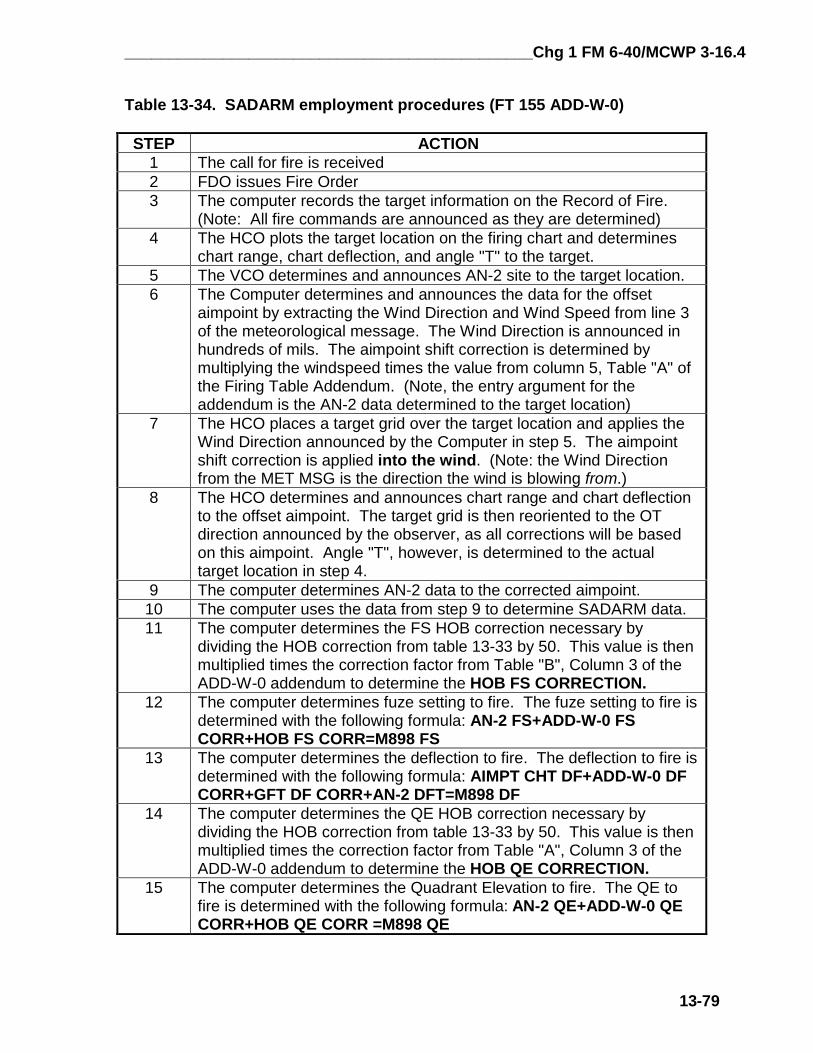
Table 13-34 contains the specific step action drill required to compute SADARM firingdata using the ADD-W-0 method.
______________________________________________Chg 1 FM 6-40/MCWP 3-16.4
13-79
Table 13-34. SADARM employment procedures (FT 155 ADD-W-0)
STEP ACTION1 The call for fire is received2 FDO issues Fire Order3 The computer records the target information on the Record of Fire.
(Note: All fire commands are announced as they are determined)4 The HCO plots the target location on the firing chart and determines
chart range, chart deflection, and angle "T" to the target.5 The VCO determines and announces AN-2 site to the target location.6 The Computer determines and announces the data for the offset
aimpoint by extracting the Wind Direction and Wind Speed from line 3of the meteorological message. The Wind Direction is announced inhundreds of mils. The aimpoint shift correction is determined bymultiplying the windspeed times the value from column 5, Table "A" ofthe Firing Table Addendum. (Note, the entry argument for theaddendum is the AN-2 data determined to the target location)
7 The HCO places a target grid over the target location and applies theWind Direction announced by the Computer in step 5. The aimpointshift correction is applied into the wind. (Note: the Wind Directionfrom the MET MSG is the direction the wind is blowing from.)
8 The HCO determines and announces chart range and chart deflectionto the offset aimpoint. The target grid is then reoriented to the OTdirection announced by the observer, as all corrections will be basedon this aimpoint. Angle "T", however, is determined to the actualtarget location in step 4.
9 The computer determines AN-2 data to the corrected aimpoint.10 The computer uses the data from step 9 to determine SADARM data.11 The computer determines the FS HOB correction necessary by
dividing the HOB correction from table 13-33 by 50. This value is thenmultiplied times the correction factor from Table "B", Column 3 of theADD-W-0 addendum to determine the HOB FS CORRECTION.
12 The computer determines fuze setting to fire. The fuze setting to fire isdetermined with the following formula: AN-2 FS+ADD-W-0 FSCORR+HOB FS CORR=M898 FS
13 The computer determines the deflection to fire. The deflection to fire isdetermined with the following formula: AIMPT CHT DF+ADD-W-0 DFCORR+GFT DF CORR+AN-2 DFT=M898 DF
14 The computer determines the QE HOB correction necessary bydividing the HOB correction from table 13-33 by 50. This value is thenmultiplied times the correction factor from Table "A", Column 3 of theADD-W-0 addendum to determine the HOB QE CORRECTION.
15 The computer determines the Quadrant Elevation to fire. The QE tofire is determined with the following formula: AN-2 QE+ADD-W-0 QECORR+HOB QE CORR =M898 QE

Chg 1 FM
6-40/MC
WP 3-16.4______________________________________________
13-80
5
Figure 13-33. Sample R
ecord of Fire for SADAR
M, FT 155 AD
D-W
-0 Method
:
SAD S/G 5 (241)
23
+ 9
H42
442 783
T-72 Platoon i/o, SADARM
2 BTRY 2 45ØØ 327Ø 232
K, 2 TGT # AA72Ø2 (2ØØ) (< 38) (15)
B 241022SFEB98 AA72Ø2
AN-2 AIMPOINT DATA (15.3) 326Ø L9 (3269) 464Ø +9 241 (250)
EOM EOM
MET MSG LINE Ø3 19 KTS (From Met Msg) AN-2 GFT SETTING: GFT B, CHG5, LOT D/G, RG 5ØØØ, EL 264, TI 16.7 (M577)Wind Dir 24ØØ Mils X 9.9 M/KT (TBL A, Col 5) GFT DF CORR L5Wind Speed 19 Knots = 188.1~19Ø Meter Aimpt shift
SADARM AIMPOINT DATA -2.Ø (13.3) LØ (3269) + 129 (379) DRIFT (L4) + GFT (L5) =
ADD-W-Ø, TBL B, COL 2 TBL A, COL 8 TBL A, COL 2
TGT ALT 445-BTRT ALT 4Ø5 VI +4Ø
FDC: K36 LAST TGT # AA72Ø1 SADARM FT 155 ADD-W-0 BTRY ALT 4Ø5
HOB CORRECTION DATA (U1ØØ/5Ø =2 INC) +Ø.2 13.5 3269 +32 411 12 SAD ADD-W- Ø TBL B, COL 3 X INC (Ø.1 X 2) = TBL A COL 3 X INC (16.1 X 2) =
+9

______________________________________________Chg 1 FM 6-40/MCWP 3-16.4
13-81
(2) ADD-W-1. No corrections to the Height of Burst are required. The AN-2graze burst data are used as entry arguments into the ADD-W-1 and the corrections to DF, FS,and QE are and applied. The FT 155 ADD-W-1 use the following formulas:
FUZE SETTING TO FIREAN-2 FS+ADD-W-1 FS CORRECTION=M898 FS
DEFLECTION TO FIREAIMPT CHT DF+ADD-W-1 DF CORR+GFT DF CORR+AN-2 DFT=M898 DF
QUADRANT ELEVATION TO FIREAN-2 QE+ADD-W-1 QE CORRECTION=M898 QE
Table 13-35. SADARM employment procedures (FT 155 ADD-W-1)
STEP ACTION1 The call for fire is received2 FDO issues Fire Order3 The computer records the target information on the Record of Fire.
(Note: All fire commands are announced as they are determined)4 The HCO plots the target location on the firing chart and determines
chart range, chart deflection, and angle "T" to the target.5 The VCO determines and announces AN-2 site to the target location.6 The Computer determines and announces the data for the offset
aimpoint by extracting the Wind Direction and Wind Speed from line 3of the meteorological message. The Wind Direction is announced inhundreds of mils. The aimpoint shift correction is determined bymultiplying the windspeed times the value from column 5, Table "A" ofthe Firing Table Addendum. (Note, the entry argument for theaddendum is the AN-2 data determined to the target location)
7 The HCO places a target grid over the target location and applies theWind Direction announced by the Computer in step 5. The aimpointshift correction is applied into the wind. (Remember, the WindDirection from the Meteorological Message is the direction the wind isblowing from.)
8 The HCO determines and announces chart range and chart deflectionto the offset aimpoint. The target grid is then reoriented to the OTdirection announced by the observer, as all corrections will be basedon this aimpoint. Angle "T", however, is determined to the actualtarget location in step 4.
9 The computer determines the FS to fire. The FS to fire is determinedwith the following formula: AN-2 FS+ADD-W-1 FS CORR = M898 FS
10 The computer determines the DF to fire. The DF to fire is determinedwith the following formula: AIMPT CHT DF+ADD-W-1 DF CORR+GFTDF CORR+AN-2 DFT=M898 DF
11 The computer determines the QE to fire. The QE to fire is determinedwith the following formula: AN-2 QE+ADD-W-1 QE CORR=M898 QE

Chg 1 FM
6-40/MC
WP 3-16.4______________________________________________
13-82
5
Figure 13-34. Sample R
ecord of Fire for SADAR
M, FT 155 AD
D-W
-1 Method
:
SAD S/G 5 (241)
23
+ 9
H42
442 783
T-72 Platoon i/o, SADARM
2 BTRY 2 45ØØ 327Ø 232
K, 2 TGT # AA72Ø2 (2ØØ) (< 38) (15)
B 241022SFEB98 AA72Ø2
AN-2 AIMPOINT DATA (15.3) 326Ø L9 (3269) 464Ø +9 241 (250)
EOM EOM
MET MSG LINE Ø3 19 KTS (From Met Msg) AN-2 GFT SETTING: GFT B, CHG5, LOT D/G, RG 5ØØØ, EL 264, TI 16.7 (M577)Wind Dir 24ØØ Mils X 9.9 M/KT (TBL A, Col 5) GFT DF CORR L5Wind Speed 19 Knots = 188.1~19Ø Meter Aimpt shift
SADARM AIMPOINT DATA -1.8 13.5 LØ 3269 + 161 411 12 SAD DRIFT (L4) + GFT (L5) =
ADD-W-1, TBL B, COL 2 TBL A, COL 8 TBL A, COL 2
TGT ALT 445-BTRT ALT 4Ø5 VI +4Ø
FDC: K36 LAST TGT # AA72Ø1 SADARM FT 155 ADD-W-1 METHOD BTRY ALT 4Ø5
+9

_____________________________________________Chg 1 FM 6-40/MCWP 3-16.4
15-7
Section IIManual Computation of Safety Data
Minimum and maximum quadrant elevations, deflection limits, and minimum fuze settingsmust be computed to ensure that all rounds fired impact or function in the target area. Thesedata are presented and arranged in a logical manner on a safety T. This section describes themanual computation of safety data by use of tabular and graphical equipment. As stated earlier,the range officer gives the OIC the lateral safety limits and the minimum and maximum ranges ofthe target areas. These data must be converted to fuze settings, deflections, and quadrants. Thecomputations discussed in this section should be done by two safety-certified personnel workingindependently.
15-4. Manual Computational Procedures
Manual safety computations are accomplished in four steps, beginning with receipt of therange safety card and ultimately ending with the production of the safety T. These steps arelisted in Table 15-1.
Table 15-1. Four Steps of Manual Safety Production.STEP ACTION
1 Receive the Range Safety Card (Produced by unit or from Range Control).2 Construct the Safety Diagram in accordance with Table 15-2.3 Construct and complete the computation matrix using Figure 15-3 for Low Angle
Safety and Figure 15-12 for High Angle Safety.4 Construct the Safety T and disseminate in accordance with unit SOP
NOTE: Figures 15-16 and 15-17 are reproducible safety computation forms
15-5. Safety Card
A Range Safety Card (Figure 15-1), which prescribes the hours of firing, the area wherethe firing will take place, the location of the firing position, limits of the target area (inaccordance with AR 385-63/MCO P3570) and other pertinent data is approved by the rangeofficer and sent to the OIC of firing. The OIC of firing gives a copy of the safety card to theposition safety officer, who constructs the safety diagram based on the prescribed limits.

Chg 1 FM 6-40/MCWP 3-16.4_____________________________________________
15-8
NOTE: The range safety card depicted in Figure 15-1 is used for all safety computationexamples in this chapter.
Range Safety CardUnit/STR K 3/11 ScheduledDateIn Ø5/30/98 ScheduledDate Out Ø5/30/98
TimeIn Ø7:ØØ TimeOut 23:59
Firing Point 185 (6Ø26 411Ø) HT 37Ø.Ø Impact Area S. CARLTON AREAWeapon M198 (155) Ammunition M1Ø7, M11Ø, M116, M825, M485, M557, M582, M732,M577
Type of Fire LOW ANGLE: HE, WP, M825, ILA, M116Type of Fire HIGH ANGLE: HE, M825, ILADirection Limits: (Ref GN): Left 134Ø MILS Right 19ØØ MILSLow Angle PD Minimum Range 39ØØ METERS Min Charge 3GBFuze TI and High Angle Minimum Range 4ØØØ METERS Min Charge 3GBTo Establish MIN Time for Fuze VT Apply +5.5 seconds to the Low Angle PD Min RgMaximum Range to Impact 62ØØ METERS Max Charge 4GB
COMMENTSFrom AZ 134Ø TO AZ 15ØØ MAXIMUM RANGE IS 57ØØ
SPECIAL INSTRUCTIONS1. SHELL ILLUMINATION (ALL CALIBERS)
A. MAX QE WILL NOT EXCEED QE FOR MAXIMUM RANGE TO IMPACTB. ONE INITIAL ILLUMINATION CHECK ROUND WILL BE FIRED TO INSURE ILLUMINATION FLARE REMAINS IN IMPACT AREAC. IF INITIAL ILLUMINATION FLARE DOES NOT LAND IN IMPACT AREA, NO FURTHER ILLUMINATION WILL BE FIRED AT THAT DF AND QE.D. INSURE THAT ALL SUCCEEDING ROUNDS ARE FIRED AT A HOB SUFFICIENT TO PROVIDE COMPLETE BURNOUT BEFORE REACHING THE GROUND.E. FOR 155MM HOWITZER, CHARGE 7 NOT AUTHORIZED WHEN FIRING PROJ ILLUM , M485.
UNCLEARED AMMUNITION(FUZES, PROJECTILES, POWDER) WILL NOT BE USED
Figure 15-1. Example of a Range Safety Card
15-6. Basic Safety Diagram
a. The FDO, on receipt of the safety card, constructs a basic safety diagram. The basicsafety diagram is a graphical portrayal of the data on the safety card or is determined from thesurface danger zone (AR 385-63, Chapter 11) and need not be drawn to scale. Shown on thebasic safety diagram are the minimum and maximum range lines; the left, right, and intermediate(if any) azimuth limits; the deflections corresponding to the azimuth limits; and the azimuth oflay.
b. The steps for constructing a basic safety diagram are shown in table 15-2. An exampleof a completed safety diagram is shown in Figure 15-2.

_____________________________________________Chg 1 FM 6-40/MCWP 3-16.4
15-9
Table 15-2. Construction of a Basic Safety Diagram.STEP ACTION
1 On the top third of a sheet of paper, draw a line representing the AOL for the firingunit. Label this line with its azimuth and the common deflection for the weaponsystem.NOTE: If the AOL is not provided, use the following procedures to determine it:Subtract the maximum left azimuth limit from the maximum right azimuth limit. Dividethis value by two, add the result to the maximum left azimuth limit, and express theresult to the nearest 100 mils. Expressing to the nearest 100 mils makes it easier forthe aiming circle operator to lay the howitzers.
2 Draw lines representing the lateral limits in proper relation to the AOL. Label theselines with the corresponding azimuth from the range safety card.
3 Draw lines between these lateral limits to represent the minimum and maximumranges. Label these lines with the corresponding ranges from the range safety card.These are the Diagram Ranges.NOTE: If the minimum range for fuze time is different from the minimum range, drawa dashed line between the lateral limits to represent the minimum range for fuze time.Label this line with the corresponding range from the range safety card. This is theminimum time Diagram Range.
4 Compute the angular measurements from the AOL to each lateral limit. On thediagram, draw arrows indicating the angular measurements and label them.
5 Apply the angular measurements to the deflection corresponding to the AOL(Common Deflection) and record the result. This will be added to the Drift and GFTDeflection Correction determined in the Safety Matrices to produce the DeflectionLimits on the Safety T. (Note: If no GFT Deflection Correction has beendetermined, then the Deflection Limits = Drift + Diagram Deflection. If a GFTsetting has been determined, then the Deflection Limits = Drift + GFT DeflectionCorrection + Diagram Deflection). Drift is applied to the Basic Safety Diagram byfollowing the "least left, most right" rule. The lowest (least) drift is applied to all leftdeflection limits, and the highest (greatest) drift is applied to all right deflection limits.
6 Label the diagram with the following information from the range safety card: firingpoint location (grid and altitude), charge, shell, fuze, angle of fire, and azimuth of lay.
c. When the basic safety diagram is complete, it will be constructed to scale, in red, on thefiring chart. Plot the firing point location as listed on the range safety card. Using temporaryazimuth indexes, an RDP, and a red pencil to draw the outline of the basic safety diagram. To dothis, first draw the azimuth limits to include doglegs. Then, by holding the red pencil firmlyagainst the RDP at the appropriate ranges, connect the azimuth lines.
d. Only after drawing the basic safety diagram on the firing chart may the base piecelocation be plotted and deflection indexes be constructed. Should the diagram be drawn from thebase piece location, it would be invalid unless the base piece was located over the firing pointmarker.
e. After the basic safety diagram has been drawn on a sheet of paper and on the firingchart, it is drawn on a map of the impact area using an RDP and a pencil. These limits must bedrawn accurately, because they will be used to determine altitudes for vertical intervals.Determine the maximum altitude along the minimum range line. This is used to ensure that thequadrant fired will cause the round to clear the highest point along the minimum range line andimpact (function) within the impact area. At the maximum range, select the minimum altitude to

Chg 1 FM 6-40/MCWP 3-16.4_____________________________________________
15-10
ensure that the round will not clear the lowest point along the maximum range. Once thealtitudes have been selected, label the basic safety diagram with the altitudes for the given ranges.
NOTE: The rule for determining the correct altitude for safety purposes is called the mini-maxrule. At the minimum range, select the maximum altitude; at the maximum range, select theminimum altitude. If the contour interval is in feet, use either the GST or divide feet by 3.28 todetermine the altitude in meters. (Feet ÷ 3.28 = Meters) This rule applies to both manual andautomated procedures.
Figure 15-2. Example of a Completed Safety Diagram, HE/WP/SMK
15-7. Computation of Low Angle Safety Data
Use the steps outlined in Table 15-3 and in the matrix in Figure 15-3 as examples fororganizing computations. The Low Angle Safety Matrix is used for all munitions except M712CLGP (Copperhead). Paragraph 15-13 describes M712 safety computations. The data aredetermined by either graphical or tabular firing tables. In the case of expelling charge munitions,the Safety Table located in the Firing Tables or Firing Table Addendums is utilized to determineElevation, Time of Flight, Fuze Setting, and Drift. (Note: the Safey Tables used for computingthe examples in this chapter are located after the Illum and M825 Low Angle examples). Useartillery expression for all computations except where noted.
Table 15-3: Low Angle ProceduresSTEP ACTION
1 On the top third of a blank sheet of paper, construct the basic safety diagram2 In the middle third of the sheet of paper, construct the Low Angle Safety Matrix3 Record the Diagram Ranges from the basic safety diagram.4 Record the Charge from the range safety card.
Min TI Rg 4000
AOF 1600 DF 3200
Max Rg 5700Min Alt 355
L 260
L 100
Min Rg 3900Max Alt 393
AZ 1340DF 3460+ L4= 3464
AZ 1500DF 3300+ L4= 3304
AZ 1900DF 2900+ L9= 2909
Max Rg 6200Min Alt 345
FP 185 (GRID 6026 4110 ALT 370) LOW ANGLE, HE/WP/SMK, CHG 4GB, AOF 1600
R 300

_____________________________________________Chg 1 FM 6-40/MCWP 3-16.4
15-11
5 Enter the Range Correction, if required. This range correction is only necessary if anonstandard condition exists and is not already accounted for in a GFT setting, suchas correcting for the always heavier than standard White Phosphorous projectile.See figure 2, paragraph (b) to determine range correction. If a range correction isrequired, it is expressed to the nearest 10 meters. If no range correction isrequired, enter 0 (zero).
6 Determine the Total Range. Total range is the sum of the Diagram Range and theRange Correction. Total Range is expressed to the nearest 10 meters.
7 Enter the Range K. Range K is only required if a GFT setting has been obtained butcannot be applied to a GFT (i.e., determining Illumination safety with a HE GFTsetting). Range K is simply the Total Range Correction from the GFT settingexpressed as a percentage. This percentage, when multiplied by the Total Range,produces the Entry Range. If no GFT setting is available (i.e., pre-occupationsafety), then enter 1.0000 as the Range K. If a GFT setting is available, (i.e., postoccupation safety), then enter the Range K expressed to four decimal places(i.e., 1.1234). Step 7a demonstrates how to compute Range K.
7a Divide Range ~ Adjusted Elevation by the Achieved Range from the GFT setting todetermine Range K: Range ~ Adjusted Elevation = Range K, expressed to four decimal places. Achieved Range
8 Determine the Entry Range. Multiply the Total Range times Range K to determine theEntry Range. If Range K is 1.0000, then the Entry Range will be identical to the TotalRange. Entry Range is expressed to the nearest 10 meters.
9 Following the Mini-Max rule, determine the Vertical Interval by subtracting the unitaltitude from the altitude corresponding to the Diagram Range, and record it. (Note:Diagram Range is used for computations of VI and Site because this is the actuallocation of the minimum range line. VI is not computed for minimum time range lines.The Range Correction, Total Range, and Range K are used to compensate fornonstandard conditions, and represent the aimpoint which must be used to cause theround to cross the Diagram Range.) VI is expressed to the nearest whole meter.
10 Compute and record Site to the Diagram Range. Use the GST from the head of theprojectile family whenever possible. Site is expressed to the nearest whole mil.
11 Determine the Elevation from Table C (base ejecting) or TFT/GFT (bursting), andrecord it. (Note: GFT Settings are not used to determine Elevation, as Range Krepresents total corrections, and to use a GFT setting would double the effects ofthose corrections). Elevation is expressed to the nearest whole mil.
12 Compute the Quadrant Elevation and record it. Quadrant Elevation is the sum ofElevation and Site. Quadrant Elevation is expressed to the nearest whole mil.
13 Determine and record the minimum fuze setting for M564/M565 fuzes. These fuzesettings correspond to the Entry Range and are extracted from Table C (base ejecting)or TFT/GFT. (Note: Minimum Fuze Settings are only determined for minimum rangelines, and may be computed for separate minimum fuze range lines). Fuze Settingsare expressed to the nearest tenth of a fuze setting increment.
14 Determine and record the minimum fuze setting for M582/M577 fuzes. These fuzesettings correspond to the Entry Range and are extracted from Table C (base ejecting)or TFT/GFT. (Note: Minimum Fuze Settings are only determined for minimum rangelines, and may be computed for separate minimum fuze range lines). Fuze Settingsare expressed to the nearest tenth of a second.
15 Determine and record the Time of Flight corresponding to the entry range from TableC, (base ejecting) or TFT/GFT. Time of Flight is expressed to the nearest tenth ofa second.
16 Determine the minimum fuze setting for M728/M732 fuzes. Add 5.5 seconds to thetime of flight, and express to the next higher whole second. The VT fuze is designed toarm 3.0 seconds before the time set. They have been known to arm up to 5.5seconds before the time set. That is why this value is added and always expressed upto the next whole second. (Note: Minimum Fuze Settings are only determined for

Chg 1 FM 6-40/MCWP 3-16.4_____________________________________________
15-12
minimum range lines, and may be computed for separate minimum fuze range lines).VT Fuze Settings are expressed up to the next higher whole second.
17 Determine and record Drift corresponding to the Entry Range from Table C (baseejecting) or TFT/GFT. Drift is applied to the Basic Safety Diagram by following the"least left, most right" rule. The lowest (least) drift is applied to all left deflection limits,and the highest (greatest) drift is applied to all right deflection limits. Drift isexpressed to the nearest whole mil.
18 Ensure computations are verified by a second safety-certified person.19 On the bottom third of the sheet of paper, record the data on the safety T.
(a) (b) (c) (d) (e) (f) (g) (h) (i) (j) (k) (l) (m) (n) (o) (p)DIAGRAM RG TOT RG ENTRY M564/ M582 M728/RG + CORR = RG x K = RG CHG VI SI + EL = QE M565 M577 TOF + 5.5 = M732 DFT
(a) This is the minimum or maximum range from the range safety diagram.
(b) This is the range correction for nonstandard conditions from Table F, if required. This is typically for preoccupation safety or corrections for nonstandard conditions not included in the Range K factor in column (d), such as WP [] weight. Examples of nonstandard conditions accounted for in (b) include, but are not limited to, difference in projectile square weight, difference in muzzle velocity, or any nonstandard condition accounted for prior to determining a Range K factor. If there is no change from standard, or all nonstandard conditions are accounted for in the Range K factor, this value is zero (0). To determine a range correction from Table F, use the following formula: NONSTANDARD STANDARD CHANGE IN RG CORR RANGE RANGE CHG CONDITION - CONDITION = STANDARD x FACTOR = CORRECTION
(c) This is the sum of the Diagram Range and the Range Correction. If there is no range correction, then the Total Range will be the same as the Diagram Range.
(d) This is the Range K factor determined by using Technique 2, Appendix F, Page F-5 in the FM 6-40/MCWP 3-16.4. This is forpost occupation safety. It represents total corrections for a registration, MET + VE, or other subsequent MET technique. It represents all nonstandard conditions (unless a separate nonstandard condition such as change in square weight for WP is listed separately in column (b)). It is multiplied times the Total Range to determine Entry Range. If there is no Range K, enter 1.0000. (e) This is the sum of the Total Range times the Range K factor. If there is no Range K factor, then the Entry Range will be the same as the Total Range. Entry Range is the range to which Elevation is determined.
(f) This is the charge from the range safety card for this set of safety computations.
(g) This is the Vertical Interval from the range safety diagram.
(h) This is the site determined to the Diagram Range by using the GST or TFT from the head of the projectile family; e.g., site for the M110 WP projectile is determined with the AM-2, M825 site is computed using the AN-2. Site is computed to the Diagram Range, as that is where the Vertical Intervals are determined.*
(i) This is the elevation from Table C (base ejecting), or GFT/TFT (bursting).*
(j) This is the sum of Elevation and Site. It is the minimum or maximum Quadrant Elevation corresponding to the Minimum or Maximum Range.
(k) This is the Minimum Fuze Setting for the M564/565 fuze from Table C (base ejecting), or GFT/TFT (bursting), corresponding to the Entry Range. */**
(l) This is the Minimum Fuze Setting for the M582/M577 fuze from Table C (base ejecting), or GFT/TFT (bursting), corresponding to the Entry range. */** (Note, this also applies to the M762, M767, and MOFA fuzes)
(m) This is the Time Of Flight from Table C (base ejecting), or GFT/TFT (bursting), corresponding to the Entry Range. */**
(n) This is the safety factor applied to the Time of Flight to determine VT fuze data. **
(o) This is the sum of TOF + 5.5. It is the Minimum Fuze Setting for M728/M732 VT fuzes. **
(p) This is the Drift corresponding to the Entry Range from Table C (base ejecting), or GFT/TFT (bursting). Drift is applied to the range safety diagram by using the "Least, Left; Most Right, “ rule. The "least" or lowest drift is applied to all left deflection limits, and the "Most" or greatest drift is applied to all right deflection limits.

_____________________________________________Chg 1 FM 6-40/MCWP 3-16.4
15-13
* - See Table 15-4 to determine the correct source table or addendum for computations.** - Computed only for minimum Entry Ranges, and only if applicable to the ammunition and the range safety card.
Figure 15-3. Low Angle Safety Matrix
4[] HE/SMK (M116) LOW ANGLE CHG 4GB
DIAGRAM RG TOT RG ENTRY M564/ M582 M728/RG + CORR = RG x K = RG CHG VI SI + EL = QE M565 M577 TOF + 5.5 = M732 DFT3900 + 0 = 3900 x 1.0000 = 3900 4GB +23 +6 + 225 = 231 -- 13.7 / 19.2 ~ 20.0 L4 4000 + 0 = 4000 x 1.0000 = 4000 4GB -- -- -- -- -- 14.1 -- -- --
5700 + 0 = 5700 x 1.0000 = 5700 4GB -15 -3 + 362 = 359 -- -- -- -- --
6200 + 0 = 6200 x 1.0000 = 6200 4GB -25 -5 + 408 = 403 -- -- -- -- L9
WP (M110, Weight Unknown) Low Angle Chg 4GB
Determining Range Correction for [] Weight Unknown Projectile
NONSTANDARD STANDARD CHANGE IN RG CORR RANGERANGE CHG CONDITION - CONDITION = STANDARD x FACTOR = CORRECTION3900 4GB 8[] - 4[] = I 4[] x +28 = +112 ~ +1104000 4GB 8[] - 4[] = I 4[] x +28 = +112 ~ +110
DIAGRAM RG TOT RG ENTRY M564/ M582 M728/RG + CORR = RG x K = RG CHG VI SI + EL = QE M565 M577 TOF + 5.5 = M732 DFT3900 + (+110) = 4010 x 1.0000 = 4010 4GB +23 (+6) + 232 = 238 -- -- -- -- --
4000 + (+110) = 4110 x 1.0000 = 4110 4GB -- -- -- -- -- 14.6 -- -- --
Figure 15-4. Completed Low Angle Safety Matrix, HE/WP/SMK
15-8. Safety T
a. The safety T is a convenient method of arranging safety data and is used to verify thesafety of fire commands (Figure 15-5). The information needed by the FDO, XO, or platoonleader, and section chief is organized in an easy to read format. The safety T is labeled with aminimum of firing point location, charge, projectiles(s), fuze(s), angle of fire, and AOL. Otheroptional entries are subject to unit SOP. Any time new safety data are determined, new safety Tsare constructed and issued only after the old safety Ts have been collected (that is, after a moveor after a registration or MET + VE). Use only one charge per Safety T. (Note: The examplesin this demonstrate which data is transferred from the Safety Matrix to the Safety Tee. This datais in bold type in the matrix and the associated safety T).
b. It is the FDO’s responsibility to ensure that all data transmitted from the FDC is withinthe limits of the safety T. It is the section chief’s responsibility to ensure that all data applied tothe ammunition or howitzer is within the limits of the safety T. The FDO must ensure thatdeflection to fire is between the deflections listed on the safety T. He then must determine if thequadrant elevation corresponding to that deflection is between the minimum and maximum QEon the safety T. Finally, he must ensure that the fuze setting is equal to or greater than theminimum fuze setting listed on the safety T for the specific fuze type.

Chg 1 FM 6-40/MCWP 3-16.4_____________________________________________
15-14
NOTE: A reproducible copy of DA Form 7353-R (Universal Safety T) is included at the end ofthis manual, in the reproducible forms section.
Figure 15-5. Example of a Completed Safety T.
Table 15-4. Tables and Addendums required for Safety Computations
WeaponSystem
SafetyRequired for:
BaseProjectile
Firing Tablefor BaseProjectile
Firing TableAddendum
M101A1 M314M444
HEHE
105-H-7105-H-7
N/AADD-B-2
M102/M119
M314M444
HEHE
105-AS-3105-AS-3
N/AADD-F-1
M198 orM109A3/A5/A6
M485M449M483A1M483A1M825M825M825A1M825A1M692/M731M718/M741M898
HEHEHEDPICMHEDPICMHEDPICMDPICMDPICMDPICM
155-AM-2155-AM-2155-AM-2155-AN-2155-AM-2155-AN-2155-AN-2155-AN-2155-AN-2155-AN-2155-AN-2
N/AADD-I-2ADD-R-1ADD-J-2ADD-T-0 w/ch1ADD-Q-O w/ch1,2ADD-T-0 w/ch1ADD-Q-0 w/ch1,2ADD-L-1 w/ch1,2ADD-N-1 w/ch1ADD-W-0
15-9. Updating Safety Data after Determining a GFT Setting
a. After a GFT setting is determined (result of registration or MET + VE technique), theFDO must compute new safety data. The GFT setting represents all nonstandard conditions ineffect at the time the GFT setting was determined (Chapter 10 and 11 discuss Total Correctionsin detail). The effect on safety is that the data determined before the GFT setting was determinedno longer represent the safety box, and could result in an unsafe condition if not applied to safety
DF
359
14.6
403
3464
238
20.0
14.1
231
3304 2909
MAX QE
MIN QE HE
MIN QE WP
MIN HE TI M582
MIN WP TI M582
MIN VT M732
FP 185, HE/WP/SMKLOW ANGLE, CHG 4GB, AOL 1600

_____________________________________________Chg 1 FM 6-40/MCWP 3-16.4
15-15
computations. In order to update safety, new elevations are determined which correspond to theminimum and maximum ranges. Deflections are modified by applying the GFT deflectioncorrection to each lateral limit. Minimum fuze settings are also recomputed. The basic safetydiagram drawn in red on the firing chart does not change. It was drawn on the basis of azimuthsand ranges, and it represents the actual limits.
b. There are two techniques which can be used to update safety computations: TheRange K Method and Applying a GFT setting to a GFT. Both methods use the same safetymatrices, and apply to both low and high angle fire. The preferred technique for updating safetyis to apply a GFT setting to the appropriate GFT. Unfortunately, not all munitions haveassociated GFTs. Application of Total Corrections is the same as for normal mission processing.The Total Corrections, in the form of a GFT setting or Range K, must be applied in accordancewith the data on which they were determined (i.e., the GFT setting for a HE registration appliesto all projectiles in the HE family, while a MET + VE for DPICM would apply to all projectilesin the DPICM family). If automation is available a false registration with M795 graze burst datamay be used to determine total corrections for all projectiles in the DPICM family (see ST 6-40-2for procedures). The principle difference between the two techniques is the manner in whichminimum fuze setting is determined.
(1) Determining Minimum Fuze Setting with a GFT with a GFT Setting Applied:When a GFT setting is applied and a fuze setting is to be determined, it is extracted opposite theTime Gage Line (if it is the fuze listed on the GFT setting) or as a function of elevation (for allothers). Use the procedures in Table 15-5 to update safety using a GFT with a GFT settingapplied. (2) Determining Fuze Setting using the Range K Technique: In order to simplifyupdating safety, the Range K technique determines all fuze settings as a function ofelevation. The difference between registered fuze settings and fuze settings determined using theRange K technique in actual firings and computer simulations varies by only zero to two tenths(0.0 – 0.2) of a Fuze Setting Increment/Second. The safety requirements in the AR 385-63 andincorporation of Minimum Fuze Setting Range Lines adequately compensate for the difference incomputational techniques. Figure 15-7 demonstrates how to update safety when no GFT isavailable, utilizing the Range K technique. Use the procedures in Table 15-3 (Low Angle) orTable 15-8 (High Angle) to update safety using the Range K method.
Table 15-5: Low Angle Procedures using a GFT with GFT Setting applied
STEP ACTION1 On the top third of a blank sheet of paper, construct the basic safety diagram in
accordance with the range safety card. (See Table 15-1 for procedures)2 In the middle third of the sheet of paper, construct the Low Angle Safety Matrix (Figure
1).3 Record the Diagram Ranges from the basic safety diagram.4 Record the Charge from the range safety card.5 Enter the Range Correction, if required. This range correction is only necessary if a
nonstandard condition exists which requires a change in aimpoint and is not alreadyaccounted for in a GFT setting, such as correcting for the always heavier thanstandard White Phosphorous projectile. See figure 2, paragraph (b) to determinerange correction. If a range correction is required, it is artillery expressed to thenearest 10 meters. If no range correction is required, enter 0 (zero).

Chg 1 FM 6-40/MCWP 3-16.4_____________________________________________
15-16
6 Determine the Total Range. Total range is the sum of the Diagram Range and theRange Correction. Total Range is expressed to the nearest 10 meters.
7 Range K. This is not used when determining data with a GFT with a GFT settingapplied, as the Elevation Gage line represents Range K.
8 Entry Range. This value is the same as the Total Range. Entry Range is artilleryexpressed to the nearest 10 meters.
9 Following the Mini-Max rule, determine the Vertical Interval by subtracting the unitaltitude from the altitude corresponding to the Diagram Range, and record it. (Note:Diagram Range is used for computations of VI and Site because this is the actuallocation of the minimum range line. VI is not determined for minimum fuze rangelines. The Range Correction, Total Range, and Range K are used to compensate fornonstandard conditions, and represent the aimpoint which must be used to cause theround to cross the Diagram Range). VI is artillery expressed to the nearest wholemeter.
10 Compute and record Site to the Diagram Range. Use the GST from the head of theprojectile family whenever possible. Site is artillery expressed to the nearest wholemil.
11 Place the MHL on the Entry Range and determine the Elevation from the ElevationGage Line on the GFT and record it. Elevation is artillery expressed to thenearest whole mil.
12 Compute the Quadrant Elevation and record it. Quadrant Elevation is the sum ofElevation and Site. Quadrant Elevation is artillery expressed to the nearest wholemil.
13 Using the procedures from Appendix G, determine and record the minimum fuzesetting for M564/M565 fuzes. These fuze settings correspond to the Entry Range. Ifthe GFT Setting was determined using the M564/M565 fuze, then determine the fuzesetting opposite the Time Gage Line. If the GFT setting was not determined using theM564/M565 fuze, then extract the fuze setting corresponding to adjusted elevation.(Note: Minimum Fuze Settings are only determined for minimum range lines, and maybe computed for separate minimum fuze range lines). Fuze Settings are artilleryexpressed to the nearest tenth of a fuze setting increment.
14 Using the procedures from Appendix G, determine and record the minimum fuzesetting for M582/M577 fuzes. These fuze settings correspond to the Entry Range. Ifthe GFT Setting was determined using the M582/M577 fuze, then determine the fuzesetting opposite the Time Gage Line. If the GFT setting was not determined using theM582/M577 fuze, then extract the fuze setting corresponding to adjusted elevation.(Note: Minimum Fuze Settings are only determined for minimum range lines, and maybe computed for separate minimum fuze range lines). Fuze Settings are artilleryexpressed to the nearest tenth of a second.
15 Using the procedures from Appendix G, determine and record the Time of Flightcorresponding to the Entry Range. Extract the Time of Flight corresponding toadjusted elevation from the TOF scale. Time of Flight is artillery expressed to thenearest tenth of a second.
16 Using the procedures in Appendix G, determine the minimum fuze setting forM728/M732 fuzes. Add 5.5 seconds to the time of flight, and express to the nexthigher whole second. (Note: Minimum Fuze Settings are only determined forminimum range lines, and may be computed for separate minimum fuze range lines).VT Fuze Settings are expressed up to the next higher whole second.
17 Determine and record Drift corresponding to adjusted elevation. Drift is applied to theBasic Safety Diagram by following the "least left, most right" rule. The smallest (least)drift is applied to all left deflection limits, and the greatest (most) drift is applied to allright deflection limits. Drift is artillery expressed to the nearest whole mil.
18 Ensure computations are verified by a second safety-certified person.19 On the bottom third of the sheet of paper, record the data on the safety T.

_____________________________________________Chg 1 FM 6-40/MCWP 3-16.4
Max Rg 5700Min Alt 355
FP 185 (GRID 6026 4110 ALT 370)LOW ANGLE, HE/WP/SMK, CHG 4GB, AOF 1600
4[] HE/SMK (M116) Low Angle Chg 4GB
DIAGRAM RG TOT RG ENTRY M564/ M582 M728/RG + CORR = RG x K = RG CHG VI SI + EL = QE M565 M577 TOF + 5.5 = M732 DFT
3900 + 0 = 3900 x 1.0449 = 4080 4GB +23 +6 + 238 = 244 -- 14.5 / 20.0 ~ 20.0 L4
4000 + 0 = 4000 x 1.0449 = 4180 4GB -- -- -- -- -- 14.8 -- -- --
5700 + 0 = 5700 x 1.0449 = 5960 4GB -15 -3 + 386 = 383 -- -- -- -- --
6200 + 0 = 6200 x 1.0449 = 6480 4GB -25 -5 + 436 = 431 -- -- -- -- L10
WP (M110, Weight Unknown) LOW ANGLE CHG 4GB
Determining Range Correction for [] Weight Unknown Projectile
NONSTANDARD STANDARD CHANGE IN RG CORR RANGERANGE CHG CONDITION - CONDITION = STANDARD x FACTOR = CORRECTION3900 4GB 8[] - 4[] = I 4[] x +28 = +112 ~ +1104000 4GB 8[] - 4[] = I 4[] x +28 = +112 ~ +110
DIAGRAM RG TOT RG ENTRY M564/ M582 M728/RG + CORR = RG x K = RG CHG VI SI + EL = QE M565 M577 TOF + 5.5 = M732 DFT
3900 + (+110) = 4010 x 1.0449 = 4190 4GB +23 (+6) + 245 = 251 -- -- -- -- --
4000 + (+110) = 4110 x 1.0449 = 4290 4GB -- -- -- -- -- 15.3 -- -- --
Figure 15-6. Post Occu
Min TI Rg 4000
AOF 1600 DF 3200
L 260
L 100
Min Rg 3900Max Alt 393
AD+=
4650
GFT K, CHG 4GB, LOT A/G, RG 4450, EL 278, TI 16.3 (M582)TOT DF CORR L10GFT DF CORR L5
16.800 RG K = 4650/4450
+ L15 ~ 1.0449= 2915
R
Max Rg 6200Min Alt 345
FP 185, HE/WP/SMK LOW ANGLE, CHG 4GB, AOL 1600GFT K, CHG 4GB, LOT A/G, RG 4450, EL 278, TI 16.3 (M582)TOT DF CORR L10 GFT DF CORR L5
AZ 1500DF 3300+ L9= 3309
pation Low Angle S
383
3469 3
AZ 1900DF 2900+ L15= 2915
AZ 190DF 290
300
Z 1340F 3460 L9 346915-17
afety, Range K Method, HE/WP/SMK
2915
15.3
431
251
20.0
14.8
244
309
MAX QE
MIN QE HE
MIN QE WP
MIN HE TI (M582)
MIN WP TI (M582)
MIN VT (M732)
DF

Chg 1 FM 6-40/MCWP 3-16.4_____________________________________________
15-18
M825 LOW ANGLE CHG 4GB
DIAGRAM RG TOT RG ENTRY RG + CORR = RG x K = RG CH
3900 + 0 = 3900 x 1.0000 = 3900 4G 4000 + 0 = 4000 x 1.0000 = 4000 4G
5700 + 0 = 5700 x 1.0000 = 5700 4G
6200 + 0 = 6200 x 1.0000 = 6200 4G
Figure 15-7. Exampl
Max Rg 5Min Alt 3
L 100
AZ 1340DF 3460+ L4= 3464
AD+=
Max Rg 6200Min Alt 345
FP 185 (GRID 6026 4110 ALT 370) LOW ANGLE, M825, CHG 4GB, AOF 1600
3464
LOW
L
Z 1500F 3300 L4 3304
M564/ M582G VI SI + EL = QE M565 M577
B +23 +6 + 254 = 260 -- --
B -- -- -- -- -- 15.1
B -15 -3 + 423 = 420 -- --
B -25 -6 + 486 = 480 -- --
e of Low Angle Safety Shel
70055
Min TI Rg 4000
AOF 1600 DF 3200
Min Rg 3900Max Alt 393
420
2909
480
15.1
260
3304
MAX QE
MIN QE M825
MIN M825 TI (M
DF
FP 185, M825 ANGLE, CHG 4GB, AOL 1600
260
AZ 1900DF 2900+ L9
= 2909 R 300M728/ TOF + 5.5 = M732 DFT
-- -- L4
-- -- --
-- -- --
-- -- L9
l M825
577)

_____________________________________________Chg 1 FM 6-40/MCWP 3-16.4
15-19
Ballistic Data for Safety ComputationsFT ADD-T-0 Projectile Improved Smoke M825
Projectile Family = DPICMEXPLANATION:
These tables contain ballistic data for safety computations. They are not to be used for computation offiring data, as they do not account for submunition/payload delivery. These tables are to be used in conjunction withChapter 15 of the FM 6-40 for safety computations only.
TABLE DATA:
The tables are arranged by charge, as follows:
CHARGE: PAGE:3G = Charge 3, M3A1 24G = Charge 4, M3A1 55G = Charge 5, M3A1 83W = Charge 3, M4A2 124W = Charge 4, M4A2 155W = Charge 5, M4A2 196W = Charge 6, M4A2 237W = Charge 7, M4A2 287R = Charge 7, M119A2 34
COLUMNAR DATA:
COLUMN:
1. Range - The distance, measured on the surface of a sphere concentric with the earth, fromthe muzzle to a target at the level point.
2. Elevation - The angle of the gun in the vertical plane required to reach the rangetabulated in column 1. The maximum elevation shown represents the highest angle atwhich predictable projectile flight is possible under standard conditions of met andmaterial.
3. Fuze Setting M577 - Fuze setting for a graze burst - numbers to be set on the fuze,MTSQ, M577 or ET, M762 that will produce a graze burst at the level point when firingunder standard conditions. This setting will produce a graze burst at the time of flightlisted in column 4.
4. Time of Flight - The projectile travel time, under standard conditions, from the muzzle tothe level point at the range in column 1. Time of flight is used as fuze setting for fuzeMTSQ M577 and fuze ET M762.
5. Azimuth correction to compensate for Drift - Because of the right hand twist of thetube, the drift of the projectile is to the right of the vertical plane of fire. This drift mustbe compensated for by a correction to the left.
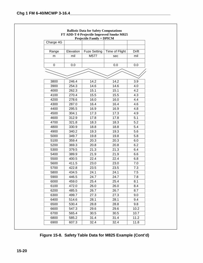
Figure 15-8. Safety Table Data for M825 Example
Chg 1 FM 6-40/MCWP 3-16.4_____________________________________________
15-20
Ballistic Data for Safety ComputationsFT ADD-T-0 Projectile Improved Smoke M825
Projectile Family = DPICMCharge 4G
Range Elevation Fuze Setting Time of Flight Driftm mil M577 sec mil
0 0.0 0.0 0.0
3800 246.4 14.2 14.2 3.93900 254.3 14.6 14.6 4.04000 262.3 15.1 15.1 4.24100 270.4 15.5 15.5 4.34200 278.6 16.0 16.0 4.44300 287.0 16.4 16.4 4.64400 295.5 16.9 16.9 4.84500 304.1 17.3 17.3 4.94600 312.9 17.8 17.8 5.14700 321.8 18.3 18.3 5.24800 330.9 18.8 18.8 5.44900 340.2 19.3 19.3 5.65000 349.7 19.8 19.8 5.85100 359.4 20.3 20.3 6.05200 369.3 20.8 20.8 6.25300 379.5 21.3 21.3 6.45400 389.9 21.9 21.9 6.65500 400.5 22.4 22.4 6.85600 411.5 23.0 23.0 7.05700 422.8 23.5 23.5 7.35800 434.5 24.1 24.1 7.55900 446.5 24.7 24.7 7.86000 459.0 25.4 25.4 8.16100 472.0 26.0 26.0 8.46200 485.5 26.7 26.7 8.76300 499.7 27.3 27.3 9.06400 514.6 28.1 28.1 9.46500 530.4 28.8 28.8 9.86600 547.3 29.6 29.6 10.26700 565.4 30.5 30.5 10.76800 585.2 31.4 31.4 11.26900 607.3 32.4 32.4 11.8
Figure 15-8. Safety Table Data for M825 Example (Cont’d)

_____________________________________________Chg 1 FM 6-40/MCWP 3-16.4
15-21
Ballistic Data for Safety ComputationsFT ADD-T-0 Projectile Improved Smoke M825
Projectile Family = DPICM
7000 632.5 33.5 33.5 12.57100 663.2 34.9 34.9 13.57200 705.5 36.7 36.7 14.9
************** ************ *************** **************** ************7200 852.1 42.4 42.4 21.07100 894.3 44.0 44.0 23.27000 924.8 45.0 45.0 25.06900 950.0 45.9 45.9 26.66800 971.9 46.6 46.6 28.26700 991.6 47.2 47.2 29.76600 1009.7 47.8 47.8 31.26500 1026.4 48.3 48.3 32.66400 1042.1 48.7 48.7 34.16300 1056.9 49.2 49.2 35.66200 1071.0 49.6 49.6 37.26100 1084.4 49.9 49.9 38.76000 1097.3 50.3 50.3 40.35900 1109.7 50.6 50.6 42.05800 1121.6 50.9 50.9 43.75700 1133.2 51.2 51.2 45.65600 1144.3 51.5 51.5 47.55500 1155.2 51.8 51.8 49.55400 1165.7 52.1 52.1 51.75300 1175.9 52.3 52.3 54.05200 1185.9 52.5 52.5 56.65100 1195.6 52.8 52.8 59.35000 1205.1 53.0 53.0 62.34900 1214.3 53.2 53.2 65.64800 1223.3 53.4 53.4 69.34700 1232.1 53.6 53.6 73.44600 1240.7 53.8 53.8 78.14500 1249.1 54.0 54.0 83.44400 1257.2 54.2 54.2 89.44300 1265.2 54.4 54.4 96.44200 1272.9 54.6 54.6 104.54100 1280.4 54.8 54.8 113.94000 1287.7 55.0 55.0 124.93900 1294.7 55.2 55.2 138.03800 1301.5 55.4 55.4 153.33700 1308.0 55.6 55.6 171.23669 1310.0
Figure 15-8. Safety Table Data for M825 Example (Cont’d)

Chg 1 FM 6-40/MCWP 3-16.4_____________________________________________
15-22
FP 185 (GRID 6026 4110 ALT 370) LOW ANGLE, M825, CHG 4GB, AOF 1600
M825 LOW ANGLE CHG
DIAGRAM RG TRG + CORR = DFT
3900 + 0 = 3 4000 + 0 = 4
5700 + 0 = 5
6200 + 0 = 6
Figure 15-9.
AZ 1340DF 3460+ L9= 3469
Max Rg 6200Min Alt 345
Max Rg 57Min Alt 355
4650
AZ 1500DF 3300+ L9= 33094GB
OT RG ENTRY RG x K = RG CHG VI SI +
900 x 1.0449 = 4080 4GB +23 +6 +
000 x 1.0449 = 4180 4GB -- --
700 x 1.0449 = 5960 4GB -15 -3 +
200 x 1.0449 = 6480 4GB -25 -6 +
Example of Post Occupatiapplied, She
451
3469
15.9
275
3309
FP 185, M8LOW ANGLE, CHG 4G
L 260
L 100
Min Rg 3900Max Alt 393
AD+=
AOF 1600 DF 3200
00 GFT K, CHG 4GB, LOT A/G, RG 4450, EL 278, TI 16.3 (M582) CORR L10 CORR L5
16.8
Z 1900F 2900 L15
TOT DFGFT DF
2915AZ 1900DF 2900 RG K = 4650/4450+ L15 ~ 1.0449 Min TI Rg 4000R 300
M564/ M582 M728/ EL = QE M565 M577 TOF + 5.5 = M732
269 = 275 -- -- -- -- L4
-- -- -- 15.9 -- -- --
454 = 451 -- -- -- -- --
527 = 521 -- -- -- -- L10
on Low Angle Safety with Range Kll M825
2915
521 MAX QE
MIN QE M825
MIN M825 TI (M577)
DF
25B, AOL 1600
= 2915

_____________________________________________Chg 1 FM 6-40/MCWP 3-16.4
FP 185 (GRID 6026 4110 ALT 370) LOW ANGLE, ILLUM, CHG 3GB, AOF 1600
ILLUM LOW ANGLE CHG 3GB
DIAGRAM RG TOT RG RG + CORR = RG x K =
3900 + 0 = 3900 x 1.0000 =
4000 + 0 = 4000 x 1.0000 =
5700 + 0 = 5700 x 1.0000 =
6200 + 0 = 6200 x 1.0000 =
Figure 15-10. E
Max Rg 57Min Alt 35
L 26AZ 1340DF 3460+ L7= 3467
Max Rg 6200Min Alt 345
493
2916
----
580
3467
----
----
16.2
297
3307
MAX Q
MIN QE
MIN Illu
D
FP 185, ILLUMLOW ANGLE, CHG 3GB AOL 1600
AZ 1500DF 3300+ L7= 3307
R 300
EFFECTIVEILLUMINATIONBOX
ENTRY M5 RG CHG VI SI + EL = QE M5
3900 3GB +23 +7 + 290 = 297 -
4000 3GB -- -- + -- = -- --
5700 3GB -15 -4 + 497 = 493 -
6200 3GB -25 -7 + 587 = 580 -
xample of Low Angle Safe
005
Min TI Rg 4000
AOF 1600 DF 3200
0
L 100
Min Rg 3900Max Alt 393
E
HE
m TI M577
F
Rg
AZ 1900DF 2900+ L16
64/ M582 M728/65 M577 TOF + 5.5 = M732 DFT
- -- -- -- L7
16.2 -- -- --
- -- -- -- --
- -- -- -- L16
= 2916
4800 Col 7 (Max Rg) RTI ~ 6196
Col 3 (FS) 16.0 M565 ~ RTI 4120Entry for Col 3 is really 16.0 after converting toM565.FDOs Call!
15-23
ty, Shell Illum

Chg 1 FM 6-40/MCWP 3-16.4_____________________________________________
15-24
Ballistic Data for Safety ComputationsFT 155-AM-2 Projectile Illumination M485/M485A1/M485A2
Projectile Family = HE
EXPLANATION:
These tables contain ballistic data for safety computations. They are not to be used for computation offiring data, as they do not account for submunition/payload delivery. These tables are to be used in conjunction withChapter 15 of the FM 6-40 for safety computations only.
TABLE DATA:
The tables are arranged by charge, as follows:
CHARGE: PAGE:1G = Charge 1, M3A1 2 (Not applicable M198 howitzer)2G = Charge 2, M3A1 43G = Charge 3, M3A1 64G = Charge 4, M3A1 95G = Charge 5, M3A1 123W = Charge 3, M4A2 164W = Charge 4, M4A2 195W = Charge 5, M4A2 236W = Charge 6, M4A2 277W = Charge 7, M4A2 328 = Charge 8, M119, M119A1 38
COLUMNAR DATA:
COLUMN:
1. Range - The distance, measured on the surface of a sphere concentric with the earth, fromthe muzzle to a target at the level point.
2. Elevation - The angle of the gun in the vertical plane required to reach the rangetabulated in column 1. The maximum elevation shown represents the highest angle atwhich predictable projectile flight is possible under standard conditions of met andmaterial.
3. Fuze Setting M565 - Fuze setting for a graze burst - numbers to be set on the fuze MT,M565 that will produce a graze burst at the level point when firing under standardconditions. This setting will produce a graze burst at the time of flight listed in column 4.
4. Time of Flight - The projectile travel time, under standard conditions, from the muzzle tothe level point at the range in column 1. Time of flight is used as fuze setting for fuzesMTSQ M577 and fuze ET M762.
5. Azimuth correction to compensate for Drift - Because of the right hand twist of thetube, the drift of the projectile is to the right of the vertical plane of fire. This drift mustbe compensated for by a correction to the left.
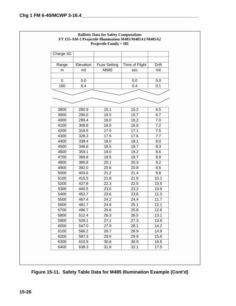
Figure 15-11. Safety Table Data for M485 Illumination Example

_____________________________________________Chg 1 FM 6-40/MCWP 3-16.4
15-25
Chg 1 FM 6-40/MCWP 3-16.4_____________________________________________
15-26
Ballistic Data for Safety ComputationsFT 155-AM-2 Projectile Illumination M485/M485A1/M485A2
Projectile Family = HE
Charge 3G
Range Elevation Fuze Setting Time of Flight Driftm mil M565 sec mil
0 0.0 0.0 0.0100 6.4 0.4 0.1
3800 280.9 15.1 15.2 6.53900 290.0 15.5 15.7 6.74000 299.4 16.0 16.2 7.04100 308.8 16.5 16.6 7.24200 318.5 17.0 17.1 7.54300 328.3 17.5 17.6 7.74400 338.4 18.0 18.1 8.04500 348.6 18.5 18.7 8.34600 359.1 19.0 19.2 8.64700 369.8 19.5 19.7 8.94800 380.8 20.1 20.3 9.24900 392.0 20.6 20.8 9.55000 403.6 21.2 21.4 9.85100 415.5 21.8 21.9 10.15200 427.8 22.3 22.5 10.55300 440.5 23.0 23.2 10.95400 453.7 23.6 23.8 11.35500 467.4 24.2 24.4 11.75600 481.7 24.9 25.1 12.15700 496.7 25.6 25.8 12.65800 512.4 26.3 26.5 13.15900 529.1 27.1 27.3 13.66000 547.0 27.9 28.1 14.26100 566.2 28.7 28.9 14.96200 587.3 29.6 29.9 15.66300 610.9 30.6 30.9 16.56400 638.3 31.8 32.1 17.5
Figure 15-11. Safety Table Data for M485 Illumination Example (Cont’d)

_____________________________________________Chg 1 FM 6-40/MCWP 3-16.4
15-27
Ballistic Data for Safety ComputationsFT 155-AM-2 Projectile Illumination M485/M485A1/M485A2
Projectile Family = HE
Charge 3G
Range Elevation Fuze Setting Time of Flight Driftm mil M565 sec mil
6500 672.1 33.2 33.5 18.86600 722.3 35.2 35.5 21.0
************* ************ ***************** **************** ************6600 842.7 39.7 40.0 27.16500 892.6 41.4 41.7 30.26400 926.2 42.5 42.8 32.56300 953.2 43.4 43.7 34.56200 976.6 44.1 44.4 36.56100 997.4 44.7 45.0 38.36000 1016.4 45.2 45.6 40.15900 1033.9 45.7 46.1 42.05800 1050.3 46.2 46.5 43.85700 1065.8 46.6 47.0 45.65600 1080.4 47.0 47.3 47.55500 1094.4 47.4 47.7 49.55400 1107.7 47.7 48.0 51.55300 1120.6 48.0 48.4 53.65200 1132.9 48.3 48.7 55.85100 1144.8 48.6 48.9 58.25000 1156.2 48.9 49.2 60.74900 1167.3 49.1 49.5 63.44800 1178.1 49.3 49.7 66.34700 1188.5 49.6 49.9 69.44600 1198.6 49.8 50.2 72.94500 1208.4 50.0 50.4 76.74400 1217.9 50.2 50.6 81.04300 1227.1 50.4 50.8 85.84200 1236.0 50.6 51.0 91.34100 1244.7 50.8 51.2 97.54000 1253.0 51.0 51.3 104.83900 1261.1 51.2 51.5 113.13800 1268.8 51.3 51.7 123.0
Figure 15-11. Safety Table Data for M485 Illumination Example (Cont’d)

Chg 1 FM 6-40/MCWP 3-16.4_____________________________________________
15-28
15-10. Determination of Maximum Effective Illumination Area
All illumination safety data are for graze burst. Therefore, when illumination firemission data are computed, the QE determined includes the appropriate HOB. This will preventachieving a 600 meter HOB (750 meter HOB for 105 mm) at the minimum and maximum rangelines. Before processing illumination fire mission, it is beneficial to determine the maximumeffective illumination area for the current range safety card. This area should be plotted on thefiring chart to help determine if illumination can be fired and to let the Forward Observers knowwhere they can fire illumination effectively. This area will always be significantly smaller thanthe HE safety area. See Table 15-6 for steps outlining the general procedure. This area can beincreased by computing High Angle data.
NOTE: The procedures used to determine the Maximum Effective Illumination Areacan be used to for all expelling charge munitions to depict their Maximum EffectiveEngagement Area.
Table 15-6. Procedures to Determine Maximum Effective Illumination Area
STEP ACTION1 Enter the TFT, Part 2, Column 7 (RTI) with the nearest range listed without exceeding the
maximum range.2 Determine the corresponding range to target in column 1. This is the maximum range the
unit can achieve a 600 meter (155mm) HOB and keep the projectile in the safety box if thefuze fails to function.
3 Determine the minimum range for which a 600 meter (155 mm) HOB is achieved and havethe fuze function no earlier than the minimum range line. Enter the TFT, Part 2, Column 3,with the nearest listed FS that is not less than the determined minimum FS. Column 3 is theFuze Setting for the M565 Fuze, so if M577 is to be used, the fuze setting must be correctedby using Table B. Determine the corresponding range to target in Column 1.
4 The area between these two lines is the maximum effective illumination area where a 600meter HOB (155mm) is achieved, the fuze functions no earlier than the minimum range line,and the round does not exceed the maximum range line if the fuze fails to function.Note: High Angle fire produces a much greater effective illumination area. The FDO mustuse Column 6, Range to Fuze Function, to determine the minimum effective illuminationrange line. The maximum effective illumination range line is determined by using fuze settingcorresponding to Column 7, Range to Impact.
15-11. Safety Considerations for M549/M549A1 RAP
RAP safety data are computed using the Low Angle Safety or High Angle Safety matrix,as appropriate. The only difference is that a safety buffer must be incorporated for rocket failureor rocket cap burn through. For firing in the Rocket-Off Mode, a 6000 meter buffer must beconstructed beyond the maximum range line to preclude the projectile exceeding the maximumrange line. For firing in the Rocket-On Mode, a 6000 meter buffer must be constructed short ofthe minimum range line to preclude the projectile falling short of the minimum range line.

_____________________________________________Chg 1 FM 6-40/MCWP 3-16.4
15-29
15-12. Safety Considerations for M864 Base Burn DPICM/M795A1 Base Burn HE
Base Burn safety data are computed using the Low Angle Safety or High Angle Safetymatrix, as appropriate. The only difference is that a safety buffer must be incorporated for BaseBurn Element Failure. A 5000 meter buffer must be constructed short of the minimum range lineto preclude the projectile falling short of the minimum range line.
15-13. Safety Procedures for M712 Copperhead
a. Copperhead safety data are determined from ballistic data developed specifically forthe Copperhead projectile. Computations are much like those for normal projectiles. TheCopperhead round should never be fired with standard data. Therefore, the computation of safetydata requires the solving of a Copperhead Met to Target technique for each listed range using theFT 155-AS-1, as covered in Chapter 13, Section 1. See Table 15-7 for steps to computeCopperhead safety. Surface Danger Zones (SDZs) for shell Copperhead are significantlydifferent than normal indirect fire SDZs. AR 385-63 (MCO P3570), chapter 11, contains theSDZs for Copperhead.
b. All ranges listed on the range safety card may not fall within the ranges listed in theTFT charge selection table for that charge and mode. Therefore, additional safety computationsmay be required for additional charge(s) and mode(s) to adequately cover the impact area. Ifranges listed on the range safety card overlap charge and mode range limitations in the chargeselection table, then safety for both affected charges and modes must be computed.
Table 15-7. Copperhead Safety Data Procedures
STEP ACTION1 Construct the basic safety diagram.
2 For low angle, circle the lower left hand corner of the safety diagram. Proceed in a clockwisemanner, and circle every other corner. For high angle, start in the lower right hand cornerand circle every other corner in a clockwise manner.
3 Complete a Copperhead Met to Target technique for each circled corner. Record the FS,deflection, and QE in the safety T. The lower left hand corner will provide the minimum FS,maximum left deflection, and minimum QE. The upper right hand corner will provide themaximum right deflection and maximum QE. Intermediate deflections and ranges willprovide intermediate deflection limits.
15-14. Computation of High Angle Safety
a. The safety data for high angle fire is computed in much the same manner as that forlow angle fire except for the ballistic variations caused by the high trajectory. Site is computeddifferently (by using the 10 mil Site Factor and the Angle of Site/10), and mechanical orelectronic fuze settings are not determined. (Note: It is the FDO’s responsibility to ensure thatall High Angle Fuze Settings will cause the fuze to function within the safety box). Table 15-8contains the steps required for computation of High Angle Safety.
b. Use the steps outlined in Table 15-8 and in the matrix in Figure 15-12 as examples fororganizing computations. The High Angle Safety Matrix is used for all munitions except M712

Chg 1 FM 6-40/MCWP 3-16.4_____________________________________________
15-30
CLGP (Copperhead). The data are determined by either graphical or tabular firing tables. In thecase of expelling charge munitions, the Safety Table located in the Firing Tables or Firing TableAddendums is utilized to determine Elevation, Time of Flight, Fuze Setting, and Drift. (Note:The Safety Tables which are used to compute the High Angle examples are located after the LowAngle Safety examples). Use artillery expression for all computations except where noted.
Table 15-8. High Angle ProceduresSTEP ACTION
1 On the top third of a blank sheet of paper, construct the basic safety diagram inaccordance with the range safety card. (See Table 15-1 for procedures)
2 In the middle third of the sheet of paper, construct the High Angle Safety Matrix(Figure 2)
3 Record the Diagram Ranges from the basic safety diagram.4 Record the Charge from the range safety card.5 Enter the Range Correction, if required. This range correction is only necessary if a
nonstandard condition exists which requires a change in aimpoint and is not alreadyaccounted for in a GFT setting, such as correcting for the always heavier thanstandard White Phosphorous projectile. See figure 2, paragraph (b) to determinerange correction. If a range correction is required, it is artillery expressed tothe nearest 10 meters. If no range correction is required, enter 0 (zero).
6 Determine the Total Range. Total range is the sum of the Diagram Range and theRange Correction. Total Range is expressed to the nearest 10 meters.
7 Enter the Range K. Range K is only required if a GFT setting has been obtained butcannot be applied to a GFT (i.e., determining Illumination safety with a HE GFTsetting). Range K is simply the Total Range Correction from the GFT settingexpressed as a percentage. This percentage, when multiplied by the Total Range,produces the Entry Range. If no GFT setting is available (i.e., pre-occupationsafety), then enter 1.000 as the Range K. If a GFT setting is available, (i.e.,post occupation safety), then enter the Range K expressed to four decimalplaces (i.e., 1.1234). Step 7a demonstrates how to compute Range K.
7a Divide Range ~ Adjusted Elevation by the Achieved Range from the GFT setting todetermine Range K: Range ~ Adjusted Elevation = Range K, expressed to four decimal places. Achieved Range
8 Determine the Entry Range. Multiply the Total Range times Range K to determinethe Entry Range. If Range K is 1.0000, then the Entry Range will be identical to theTotal Range. Entry Range is artillery expressed to the nearest 10 meters.
9 Following the Mini-Max rule, determine the Vertical Interval by subtracting the unitaltitude from the altitude corresponding to the Diagram Range, and record it.(Note: Diagram Range is used for computations of VI and Site because this is theactual location of the minimum range line. The Range Correction, Total Range, andRange K are used to compensate for nonstandard conditions, and represent theaimpoint which must be used to cause the round to cross the Diagram Range). VIis artillery expressed to the nearest whole meter.
10 Determine and record the Angle of Site divided by 10 to the Diagram Range. Thisis performed by dividing the Angle of Site (use the appropriate GST, if possible) by10. <SI/10 is artillery expressed to the nearest tenth of a mil, and has the samesign as the VI.
11 Determine and record the 10 mil Site Factor from the GFT or TFT which heads theprojectile family. (Note: Remember to use the Diagram Range to compute 10 milSi Fac). 10 mil Si Fac is artillery expressed to the nearest tenth of a mil and is always negative.
12 Compute and record Site. Site is the product of <SI/10 times 10 mil Si Fac. Site isartillery expressed to the nearest whole mil.
13 Determine the Elevation from Table C (base ejecting) or TFT/GFT (bursting), and

_____________________________________________Chg 1 FM 6-40/MCWP 3-16.4
15-31
record it. (Note: GFT Settings are not used to determine Elevation, as Range Krepresents total corrections, and to use a GFT setting would double the effects ofthose corrections). Elevation is artillery expressed to the nearest whole mil.
14 Compute the Quadrant Elevation and record it. Quadrant Elevation is the sum ofElevation and Site. Quadrant Elevation is artillery expressed to the nearestwhole mil.
15 Determine and record Drift corresponding to the Entry Range from Table C (baseejecting) or TFT/GFT. Drift is applied to the Basic Safety Diagram by following the"left least, right most" rule. The lowest (least) drift is applied to all left deflectionlimits, and the highest (greatest) drift is applied to all right deflection limits. Drift isartillery expressed to the nearest whole mil.
16 Ensure computations are verified by a second safety-certified person.17 On the bottom third of the sheet of paper, record the data on the safety T.
NOTE: Minimum fuze settings are not computed for High Angle safety. It is the FDO'sresponsibility to ensure that all fuze settings will cause the projectile to function in theimpact area.
(a) (b) (c) (d) (e) (f) (g) (h) (I) (j) (k) (l) (m)DIAGRAM RG TOT RG ENTRYRG + CORR = RG x K = RG CHG VI <SI/10 X10mil Si Fac = SI + EL = QE DRIFT
(a) This is the minimum or maximum range from the range safety diagram.
(b) This is the range correction for nonstandard conditions from Table F, if required. This is typically for reoccupation safety or corrections for nonstandard conditions not included in the Range K factor in column (d), such as WP [] weight. Examples of nonstandard conditions accounted for in (b) include, but are not limited to, difference in projectile square weight, difference in muzzle velocity, or any nonstandard condition accounted for prior to determining a Range K factor. If there is no change from standard, or all nonstandard conditions are accounted for in the Range K factor, this value is zero (0). To determine a range correction from Table F, use the following formula: NONSTANDARD STANDARD CHANGE IN RG CORR RANGE RANGE CHG CONDITION - CONDITION = STANDARD x FACTOR = CORRECTION
(c) This is the sum of the Diagram Range and the Range Correction. If there is no range correction, then the Total Range will be the same as the Diagram Range.
(d) This is the Range K factor determined by using technique 2 in the FM 6-40/MCWP 3-16.6. This is for post occupation safety. It represents total corrections for a registration, MET + VE, or other subsequent MET technique. It represents all nonstandard conditions (unless a separate nonstandard condition such as change in square weight for WP is listed separately in column (b)). It is multiplied times the Total Range to determine Entry Range. If there is no Range K, enter 1.0000 (e) This is the sum of the Total Range times the Range K factor. If there is no Range K factor, then the Entry Range will be the same as the Total Range. Entry Range is the range to which Elevation is determined.
(f) This is the charge from the range safety card for this set of safety computations.
(g). This is the Vertical Interval from the range safety diagram.
(h). This is the Angle of Site divided by 10, determined by dividing Vertical Interval by Entry Range in Thousands.(i). This is the 10 mil Site Factor, determined from the GFT or TFT from the head of the projectile family; e.g., 10 mil Site Factor for the M110 WP projectile would be determined with the AM-2, M825 10 mil Site Factor would be computed using the AN-2. *
(j). This is Site, the product of <Site/10 X 10 Mil Site Factor (Note: Site is determined for the Diagram Range). *
(k). This is the elevation to impact from Table C (base ejecting), or GFT/TFT (bursting). *
(l). This is the sum of Elevation and Site. It is the minimum or maximum Quadrant Elevation corresponding to

Chg 1 FM 6-40/MCWP 3-16.4_____________________________________________
15-32
maximum or minimum range.
(m). This is the Drift corresponding to Table C (base ejecting), or GFT/TFT (bursting), Drift is applied to the range safety diagram by using the "Least, Left; Most, Right;" rule. The "least" or lowest drift is applied to all left deflection limits, and the "most" or greatest drift is applied to all right deflection limits.
* - see Table 15-8 to determine the correct source table or addendum for computations/
Figure 15-12. High Angle Safety Matrix
4[] HE HIGH ANGLE CHG 3GB
DIAGRAM RANGE TOTAL RANGE ENTRY RANGE + CORR = RANGE X k__ = RANGE CHG VI <SI/10 X 10mil Si Fac = SI + EL = QE DRIFT
4000 + 0 = 4000 x 1.0000 = 4000 3GB +23 +0.6 x -1.0 = -1 + 1247 = 1246 L101
5700 + 0 = 5700 x 1.0000 = 5700 3GB -15 -0.3 x -5.2 = +2 + 1052 = 1054 --
6200 + 0 = 6200 x 1.0000 = 6200 3GB -25 -0.4 x -15.0 = +6 + 954 = 960 L34
FP 185, HEHIGH ANGLE, CHG 3GB, AOL 1600
Figure 15-13. Example of High Ang
1246
3494 3334 3001
1054 960
Max Rg 5700Min Alt 355
AOF 1600 DF 3200
L 260
Min Rg 4000Max Alt 393
= 3334
Max Rg 6200Min Alt 345
FP 185 (GRID 6026 4110 ALT 370) HIGH ANGLE, HE, CHG 3GB, AOF 1600
AZ 1340DF 3460+ L34= 3494
R 300
L 100
MAX QEMAX QE
AZ 1500DF 3300+ L34
MIN QE
le Safety
DF
MIN QE
AZ 1900DF 2900+ L101= 3001
, Shell HE

_____________________________________________Chg 1 FM 6-40/MCWP 3-16.4
M825 HIGH ANGLE CHG 4GB
DIAGRAM RANGE TOTAL RANGE ENRANGE + CORR = RANGE X __k__ = R
4000 + 0 = 4000 x 1.0000 = 4
5700 + 0 = 5700 x 1.0000 = 5
6200 + 0 = 6200 x 1.0000 = 6
HIGH AN
Figure 15-14. Exam
FP 185 (GRID 6026 4110 ALT 370) HIGH ANGLE, M825, CHG 4GB, AOF 1600
Max Rg 5700Min Alt 355
L 260AZ 1340DF 3460+ L37= 3497
AD+=
Max Rg 6200Min Alt 345
3497
Z 1500F 3300 L37 3337
R 300
MAX QE
MIN QE
TRYANGE CHG VI <SI/10 X 10mil S
000 4GB +23 +0.6 x -0.7
700 4GB -15 -0.3 x -2.8
200 4GB -25 -0.4 x -4.4
FP 185, M825GLE, CHG 4GB, AOL 1600
ple of High Angle Safety
Min TI Rg 4000
AOF 1600 DF 3200
L 100
Min Rg 3900Max Alt 393
AD+=
1288
1134 1073
3337 3025 DF
MAX QE
MIN QE
MAX QE
MIN QE
R 300
Z 1900F 2900 L125
3025
15-33
i Fac = SI + EL = QE DRIFT
= 0 + 1288 = 1288 L125
= +1 + 1133 = 1134 --
= +2 + 1071 = 1073 L37
, Shell M825

Chg 1 FM 6-40/MCWP 3-16.4_____________________________________________
15-34
41.1 5200
FP 185 (GRID 6026 4110 ALT 370)HIGH ANGLE, ILLUM, CHG 3GB, AOF 1600
ILLUM HIGH ANGLE CHG 3GB
DIAGRAM RANGE TOTAL RANGE ERANGE + CORR = RANGE X __k__ = R
4000 + 0 = 4000 x 1.0000 =
5700 + 0 = 5700 x 1.0000 =
6200 + 0 = 6200 x 1.0000 =
HIGH A
Figure 15-15. Exam
349
Max Rg 57Min Alt 35
L 260AZ 1340DF 3460+ L36= 3496
Max Rg 6200Min Alt 345
AZ 1500DF 3300+ L36= 3336
MAX QE
MIN QE
R 300
4200
5600
NTRYANGE CHG VI <SI/10 X 10mil Si
4000 3GB +23 +0.6 x -1.0
5700 3GB -15 -0.3 x -5.3
6200 3GB -25 -0.4 x -15.0
FP 185, ILLUMNGLE, CHG 3GB, AOL 1600
ple of High Angle Safety,
1252
1068 983
6 3336 3005 DF
Rang44.2+0.344.5
38.3 M+0.3 C38.6 S
005
Min TI Rg 4000
AOF 1600 DF 3200
L 100
Min Rg 3900Max Alt 393
MAX QE
MIN QE
R 300
AZ 1900DF 2900+ L105= 3005
Fac = SI + EL = QE DRIFT
= -1 + 1253 = 1252 L105
= +2 + 1066 = 1068 --
= +6 + 977 = 983 L36
565ORR for M577
EFFECTIVEILLUMINATIONBOX
e to Fuze Function
EC
40.8+0.3
40.8+0.341.1
Shell Illum
SEC

_____________________________________________Chg 1 FM 6-40/MCWP 3-16.4
15-35
FIGURE 15-16: LOW ANGLE SAFETY COMPUTATIONSSafety Diagram
Location (Grid/Alt): Charge: Shell(s): Fuze(s): Angle of Fire:AOL:
Low Angle Safety Matrix
Chg:_____ Shell(s):__________ Fuze(s):__________ Projectile Family:__________
DIAGRAM RG TOT RG ENTRY M564/ M582 M728/RG + CORR = RG x K = RG CHG VI SI + EL = QE M565 M577 TOF + 5.5 = M732 DFT
Safety TLocation:____________Charge: _____Shell(s):___________Fuze(s):__________Angle of Fire:___ AOL: ____
AOF DF

Chg 1 FM 6-40/MCWP 3-16.4_____________________________________________
15-36
FIGURE 15-17: HIGH ANGLE SAFETY COMPUTATIONSSafety Diagram
Location (Grid/Alt): Charge: Shell(s): Angle of Fire:AOL:
High Angle Safety Matrix
Chg:_____ Shell(s):__________ Projectile Family:__________
DIAGRAM RG TOT RG ENTRYRG + CORR = RG x K = RG CHG VI <SI/10 x 10 mil Si Fac = SI + EL = QE DFT
Safety TLocation:_________________Charge: _____Shell(s):__________Angle of Fire:_____AOL:________
AOF DF

_____________________________________________Chg 1 FM 6-40/MCWP 3-16.4
15-37
Section IIIMinimum Quadrant Elevation
The XO or platoon leader is responsible for determining the lowest QEthat can be safely fired from his position that will ensure projectiles clear allvisible crests (minimum QE).
15-15. Elements of Computation
A minimum quadrant for EACH howitzer is ALWAYS determined. The maximumof these minimum quadrants is the XO’s minimum quadrant. Use of the rapid fire tables inST 6-50-20 is the fastest method of computing minimum QE. The QE determined from ST 6-50-20 is always equal to or greater than (more safe) than manual computations. Manualcomputations are more accurate than the rapid fire tables and are used if the sum of the site tocrest and the angle needed for a 5-meter vertical clearance is greater than 300 mils. Figure 15-18shows the elements of minimum QE.
a. Piece-to-crest range (PCR) is the horizontal distance between the piece and the crest,expressed to the nearest 100 meters. Procedures for measurement are discussed in paragraph15-16.
NOTE: All angles are determined and expressed to the next higher mil.
b. Angle 1 (Figure 15-18) is the angle of site to crest measured by the weapons. Seeparagraph 15-16 for procedures.
c. Angle 2 (Figure 15-18) is the vertical angle required to clear the top of the crest. Forquick, time, and unarmed proximity (VT) fuzes, a vertical clearance of 5 meters is used. Forarmed VT fuzes, see paragraph 15-19.
d. Angle 3 (Figure 15-18) is the complementary angle of site. It is the complementarysite factor (TFT, Table G) for the appropriate charge at the piece to crest range mulitiplied by thesum of angles 1 and 2. Site is the sum of angles 1, 2, and 3.
NOTE: The entry argument for Table G is PCR. If it is not listed, do not interpolate,use the next higher listed value.
e. Angle 4 (Figure 15-18) is the elevation (TFT, Table F) for the appropriate chargecorresponding to the PCR.
f. Angle 5 (Figure 15-18) is a safety factor equivalent to the value of 2 forks (TFT, TableF) for the appropriate charge at the PCR.
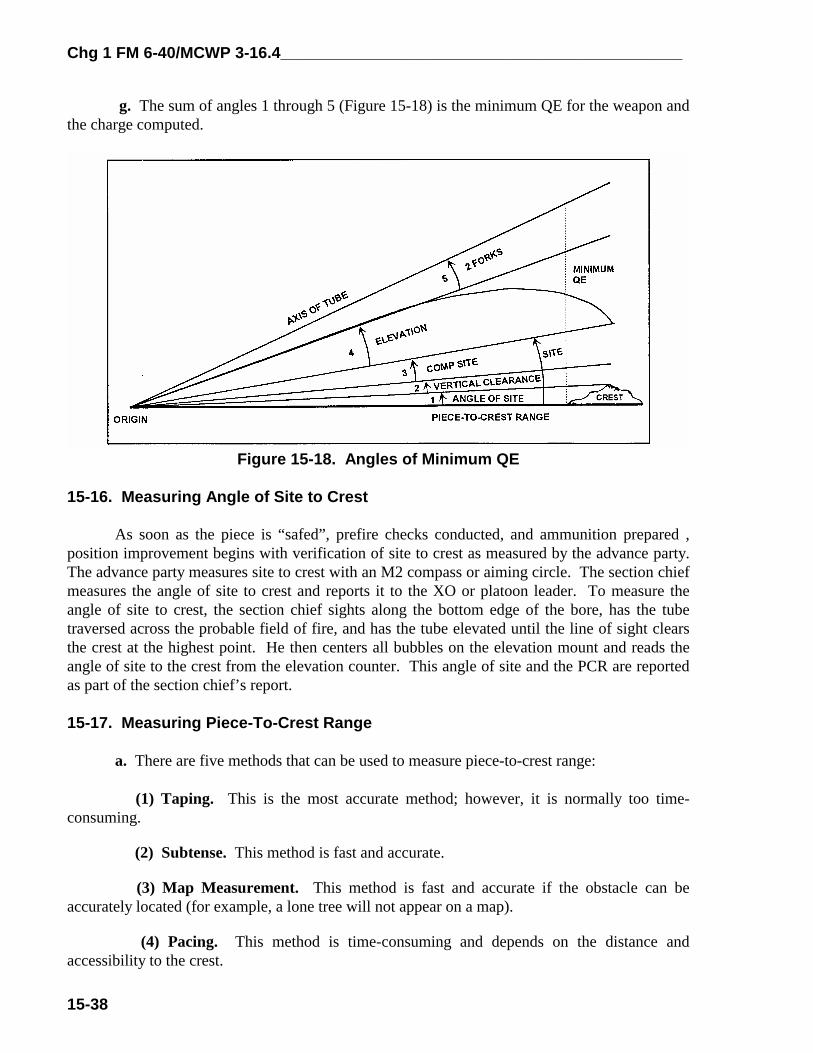
Chg 1 FM 6-40/MCWP 3-16.4_____________________________________________
15-38
g. The sum of angles 1 through 5 (Figure 15-18) is the minimum QE for the weapon andthe charge computed.
Figure 15-18. Angles of Minimum QE
15-16. Measuring Angle of Site to Crest
As soon as the piece is “safed”, prefire checks conducted, and ammunition prepared ,position improvement begins with verification of site to crest as measured by the advance party.The advance party measures site to crest with an M2 compass or aiming circle. The section chiefmeasures the angle of site to crest and reports it to the XO or platoon leader. To measure theangle of site to crest, the section chief sights along the bottom edge of the bore, has the tubetraversed across the probable field of fire, and has the tube elevated until the line of sight clearsthe crest at the highest point. He then centers all bubbles on the elevation mount and reads theangle of site to the crest from the elevation counter. This angle of site and the PCR are reportedas part of the section chief’s report.
15-17. Measuring Piece-To-Crest Range
a. There are five methods that can be used to measure piece-to-crest range:
(1) Taping. This is the most accurate method; however, it is normally too time-consuming.
(2) Subtense. This method is fast and accurate.
(3) Map Measurement. This method is fast and accurate if the obstacle can beaccurately located (for example, a lone tree will not appear on a map).
(4) Pacing. This method is time-consuming and depends on the distance andaccessibility to the crest.
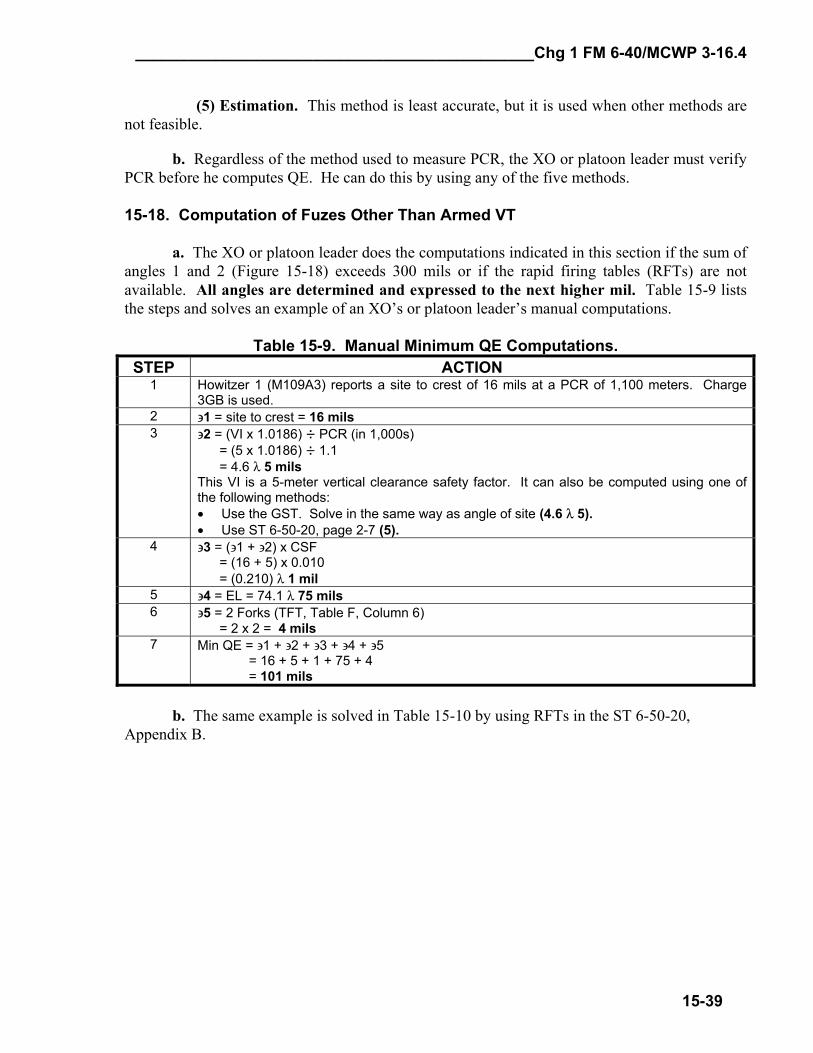
_____________________________________________Chg 1 FM 6-40/MCWP 3-16.4
15-39
(5) Estimation. This method is least accurate, but it is used when other methods are not feasible.
b. Regardless of the method used to measure PCR, the XO or platoon leader must verify PCR before he computes QE. He can do this by using any of the five methods. 15-18. Computation of Fuzes Other Than Armed VT a. The XO or platoon leader does the computations indicated in this section if the sum of angles 1 and 2 (Figure 15-18) exceeds 300 mils or if the rapid firing tables (RFTs) are not available. All angles are determined and expressed to the next higher mil. Table 15-9 lists the steps and solves an example of an XO’s or platoon leader’s manual computations.
Table 15-9. Manual Minimum QE Computations. STEP ACTION
1 Howitzer 1 (M109A3) reports a site to crest of 16 mils at a PCR of 1,100 meters. Charge 3GB is used.
2 ∋1 = site to crest = 16 mils 3 ∋2 = (VI x 1.0186) ÷ PCR (in 1,000s)
= (5 x 1.0186) ÷ 1.1 = 4.6 λ 5 mils This VI is a 5-meter vertical clearance safety factor. It can also be computed using one of the following methods: • Use the GST. Solve in the same way as angle of site (4.6 λ 5). • Use ST 6-50-20, page 2-7 (5).
4 ∋3 = (∋1 + ∋2) x CSF = (16 + 5) x 0.010 = (0.210) λ 1 mil
5 ∋4 = EL = 74.1 λ 75 mils 6 ∋5 = 2 Forks (TFT, Table F, Column 6)
= 2 x 2 = 4 mils 7 Min QE = ∋1 + ∋2 + ∋3 + ∋4 + ∋5
= 16 + 5 + 1 + 75 + 4 = 101 mils
b. The same example is solved in Table 15-10 by using RFTs in the ST 6-50-20, Appendix B.

Chg 1 FM 6-40/MCWP 3-16.4_____________________________________________
15-40
Table 15-10. RFT Minimum QE Computations.STEP ACTION
1 Determine if the RFT can be used (∋∋∋∋ 1 + ∋∋∋∋ 2 [[[[ 300 mils). Use the ST 6-50-20, page A-1.Since the sum of angles 1 and 2 is less than or equal to 300 (16 +5 = 21), the RFT can beused.
2 Determine RFT value. Enter the appropriate RFT. The entry arguments are howitzer(M109A3), propellant (M3A1, GB), fuze (PD), PCR (1100), and charge (3). The correcttable is on page A-7. The RFT value is 86. This value equals the sum of angles 2, 3, 4,and 5 (∋∋∋∋ 2 + ∋∋∋∋ 3 + ∋∋∋∋ 4 + ∋∋∋∋ 5).NOTE: Use the RFT labeled “M557, M564” for all minimum QE computations exceptarmed VT. For armed VT, use the RFT labeled “M728.”
3 Determine the RFT minimum QE. This value equals the sum of angle 1 and the RFTvalue (16 + 86 = 102).
c. One howitzer section may report a site to crest that is unusually high. If the XO orplatoon leader determines that it is the result of a single narrow obstruction (such as a tree), thepiece can be called out of action when firing a deflection that would engage the obstruction. Thiswould enable the platoon to use the next lower site to crest. Other alternatives are to remove theobstruction or move the weapon.
d. Table 15-11 illustrates why minimum QE is computed for all guns, regardless ofwhich has the largest site to crest.
Table 15-11. RFT Example for Howitzer Platoon.
GUN CHG PCRSITE TOCREST + RFT = MIN QE
1 3GB 800 128 64 1922 3GB 1000 105 80 1853 3GB 1500 92 116 2084 3GB 1200 115 93 208
15-19. Computations for Armed VT Fuze (Low-Angle Fire)
a. The method of computing the XO’s minimum QE for firing a projectile fuzed with anM728 or M732 fuze depends on the method in which the fuze is used. The proximity (VT) fuzeis designed to arm 3 seconds before the time set on the fuze; however, some VT fuzes havearmed as early as 5.5 seconds before the time set on the fuze. Because of the probability ofpremature arming, a safety factor of 5.5 seconds is added to the time of flight to the PCR.Since time on the setting ring is set to the whole second, the time determined in computingminimum safe time is expressed up to the nearest whole second. A VT fuze is designed so that itwill not arm earlier than 2 seconds into its time of flight, which makes it a bore-safe fuze.
b. In noncombat situations, the XO or platoon leader determines the minimum safe timeby adding 5.5 seconds to the time of flight to the minimum range line as shown on the rangesafety card. The minimum QE determined for fuzes quick and time is also valid for fuze VT.
c. In combat situations, the XO or platoon leader determines the minimum QE and aminimum safe time for fuze VT. The minimum QE determined for PD fuzes is safe for VT fuzes
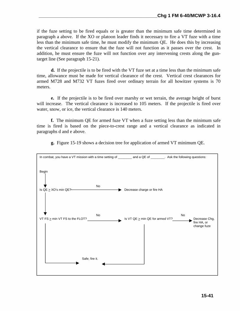
_____________________________________________Chg 1 FM 6-40/MCWP 3-16.4
15-41
if the fuze setting to be fired equals or is greater than the minimum safe time determined inparagraph a above. If the XO or platoon leader finds it necessary to fire a VT fuze with a timeless than the minimum safe time, he must modify the minimum QE. He does this by increasingthe vertical clearance to ensure that the fuze will not function as it passes over the crest. Inaddition, he must ensure the fuze will not function over any intervening crests along the gun-target line (See paragraph 15-21).
d. If the projectile is to be fired with the VT fuze set at a time less than the minimum safetime, allowance must be made for vertical clearance of the crest. Vertical crest clearances forarmed M728 and M732 VT fuzes fired over ordinary terrain for all howitzer systems is 70meters.
e. If the projectile is to be fired over marshy or wet terrain, the average height of burstwill increase. The vertical clearance is increased to 105 meters. If the projectile is fired overwater, snow, or ice, the vertical clearance is 140 meters.
f. The minimum QE for armed fuze VT when a fuze setting less than the minimum safetime is fired is based on the piece-to-crest range and a vertical clearance as indicated inparagraphs d and e above.
g. Figure 15-19 shows a decision tree for application of armed VT minimum QE.
In combat, you have a VT mission with a time setting of ________ and a QE of ________. Ask the following questions:
Begin
NoIs QE > XO’s min QE? Decrease charge or fire HA
No NoVT FS > min VT FS to the FLOT? Is VT QE > min QE for armed VT? Decrease Chg,
fire HA, or change fuze
Safe; fire it.
Chg 1 FM 6-40/MCWP 3-16.4_____________________________________________
15-42
Figure 15-19. Armed VT Decision Tree.
h. Table 15-12 is an example of computations to determine minimum QE for an armedVT fuze.

_____________________________________________Chg 1 FM 6-40/MCWP 3-16.4
15-43
Table 15-12. Manual Armed VT Minimum QE Computations.STEP ACTION
1 Howitzer 1 (M109A3) reports a site to crest of 16 mils at a PCR of 1,100 meters. Charge3GB is used.
2 ∋ 1 = site to crest = 16 mils3 ∋ 2 = (VI x 1.0186) + PCR (in 1,000s)
=(70 x 1.0186) + 1.1 = 64.8 λ 65 milsThis VI is a 70-meter vertical clearance safety factor. It can also be computed by using theGST. Solve in the same way as angle of site (64.7 λλλλ 65).
4 ∋ 3 = (∋ 1 + ∋ 2) x CSF (TFT, Table G) = (16 + 65) x 0.010 = 0.710 λ 1 mil
5 ∋ 4 = EL = 74.1 λ 75 mils6 ∋ 5 = 2 Forks (TFT, Table F, Column 6)
= 2 x 2 = 4 mils7 Min QE = ∋ 1 + ∋ 2 + ∋ 3 + ∋ 4 + ∋ 5
= 16 + 65 + 1 + 75 + 4 = 161 mils
8 Determine minimum safe time. This value is the sum of TOF to PCR and 5.5 expressed upto the next higher second (4.1 + 5.5 = 9.6 λλλλ 10.0 sec).
i. The same example is solved in Table 15-13 by using the RFT in the ST 6-50-20,Appendix A.
Table 15-13 RFT Minimum QE Computations.STEP ACTION
1 Determine if the RFT can be used (∋ 1 + ∋ 3 [ 300 mils). This is done manually, since page A-1 uses a vertical clearance of 5 meters. See step 3 in table 15-12 for ∋ 2. Since the sum ofangles 1 and 2 is less than or equal to 300 (16 +65 = 81), the RFT can be used.
2 Determine RFT value. Enter the appropriate RFT. The entry arguments are howitzer(M109A3), propellant (M3A1, GB), fuze (M728 or M732), PCR (1100) and charge (3). Thecorrect table is on page A-13. The RFT value is 147. This value equals the sum of angles 2,3, 4, and 5.NOTE: Use the RFT labeled “M557, M564” for all minimum QE computations except armedVT. For armed VT, use the RFT labeled “M728.”
3 Determine the RFT minimum QE. This value equals the sum of angle 1 and the RFT value(16 + 147 = 163).
4 Determine the minimum safe time. Use the same entry arguments as in step 2. Theminimum safe time is 10.0.
j. If the VT fuze setting to be fired is equal to or greater than the minimum safe VT time,the minimum QE for fuzes quick and time applies. If the VT fuze setting to be fired is less thanthe minimum safe VT time, the minimum QE determined for armed VT applies.
15-20. Using Minimum Quadrant Elevation
After computing minimum QE for each charge authorized, the XO or platoon leader mustcompare the minimum QE to the QE required to clear the minimum range line. The XO mustthen select the highest quadrant for each charge to be used as the minimum QE to be fired fromthat position.

Chg 1 FM 6-40/MCWP 3-16.4_____________________________________________
15-44
15-21. Intervening Crest
a. FDOs must ensure that artillery fires clear intervening crests. Intervening crests aredefined as any obstruction between the firing unit and the target not visible from the firing unit.The following are the possible options, listed in order of preference.
(1) Determine firing data to the crest (include all nonstandard conditions) and add 2forks (Table 15-12).
(2) Determine a minimum QE in a similar manner as XO’s minimum QE (Table15-13).
(3) Use the trajectory tables in the appendix of the TFT.
b. Option 1 is preferred because it incorporates all current nonstandard conditions thatwill affect the projectile along the trajectory. The FDO has the responsibility to determine onthe basis of availability of corrections for nonstandard conditions if this really is the bestoption. Table 15-12 lists the steps.
Table 15-14. Intervening Crest, Option 1.STEP ACTION
1 Upon occupation, the FDO analyzes the terrain for intervening crests.2 Upon determining the altitude of this crest, he computes firing data to this point (QE). The
best solution includes all available corrections for nonstandard conditions (current and validGFT setting).
3 Add the value of 2 forks (TFT, Table F, Column 6) to the QE determined in step 2 to ensurethat round-to-round variations (probable errors) will clear the crest.
4 The FDO then records this QE and charge on his situation map as a check to ensure thatrounds will clear the intervening crest.
5 Upon receipt of a fire mission, the FDO will compare his intervening crest QE to his firemission quadrant. One of the three following situations will occur:
1) The target is located short of the intervening crest. The FDO does not consider the effectsof the crest at this time.
2) The mission QE exceeds intervening crest QE by a significant margin, indicating therounds will clear the crest.
3) Fire mission QE exceeds intervening crest QE by only a small margin or is less thanintervening crest QE, indicating the round may or may not clear the crest. The FDO mustdetermine if the round will clear after considering the following:
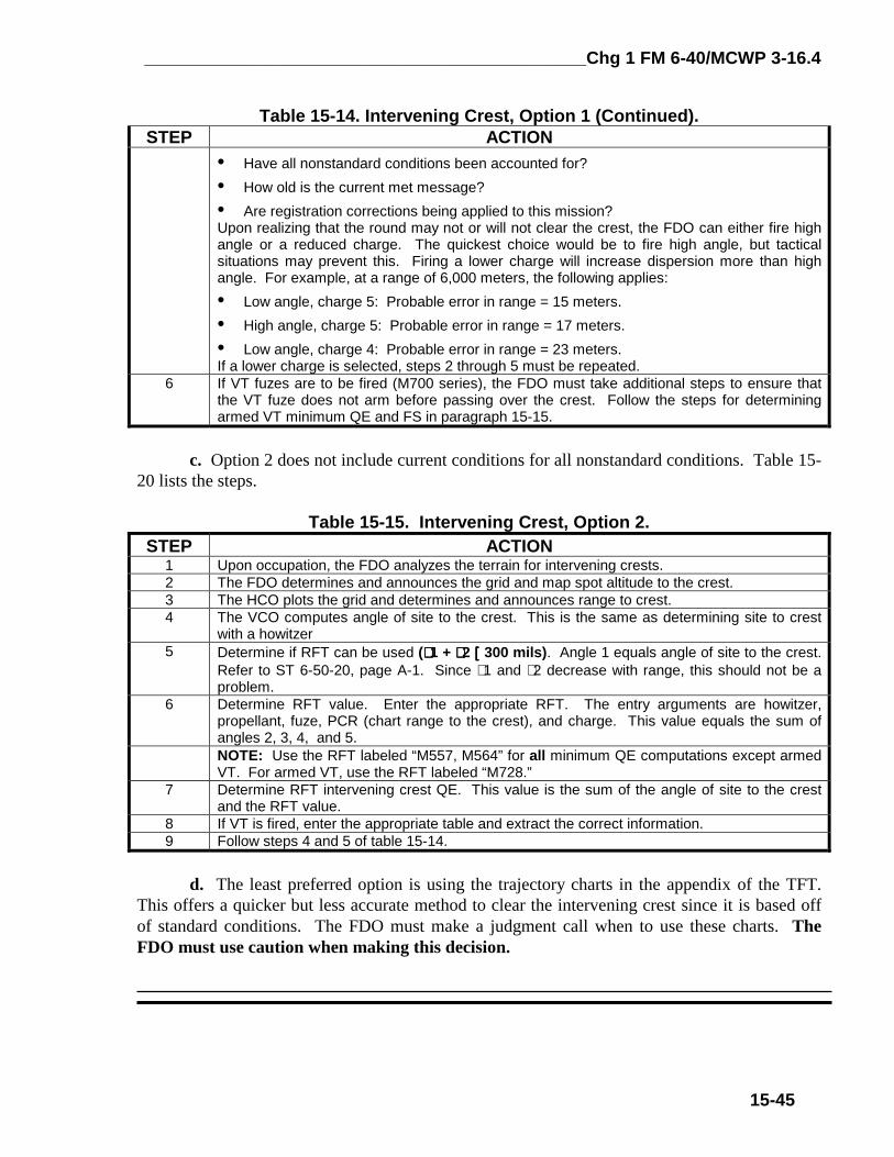
_____________________________________________Chg 1 FM 6-40/MCWP 3-16.4
15-45
Table 15-14. Intervening Crest, Option 1 (Continued).STEP ACTION
• Have all nonstandard conditions been accounted for?• How old is the current met message?• Are registration corrections being applied to this mission?Upon realizing that the round may not or will not clear the crest, the FDO can either fire highangle or a reduced charge. The quickest choice would be to fire high angle, but tacticalsituations may prevent this. Firing a lower charge will increase dispersion more than highangle. For example, at a range of 6,000 meters, the following applies:• Low angle, charge 5: Probable error in range = 15 meters.• High angle, charge 5: Probable error in range = 17 meters.• Low angle, charge 4: Probable error in range = 23 meters.If a lower charge is selected, steps 2 through 5 must be repeated.
6 If VT fuzes are to be fired (M700 series), the FDO must take additional steps to ensure thatthe VT fuze does not arm before passing over the crest. Follow the steps for determiningarmed VT minimum QE and FS in paragraph 15-15.
c. Option 2 does not include current conditions for all nonstandard conditions. Table 15-20 lists the steps.
Table 15-15. Intervening Crest, Option 2.STEP ACTION
1 Upon occupation, the FDO analyzes the terrain for intervening crests.2 The FDO determines and announces the grid and map spot altitude to the crest.3 The HCO plots the grid and determines and announces range to crest.4 The VCO computes angle of site to the crest. This is the same as determining site to crest
with a howitzer5 Determine if RFT can be used (∋∋∋∋ 1 + ∋∋∋∋ 2 [[[[ 300 mils). Angle 1 equals angle of site to the crest.
Refer to ST 6-50-20, page A-1. Since ∋ 1 and ∋ 2 decrease with range, this should not be aproblem.
6 Determine RFT value. Enter the appropriate RFT. The entry arguments are howitzer,propellant, fuze, PCR (chart range to the crest), and charge. This value equals the sum ofangles 2, 3, 4, and 5.NOTE: Use the RFT labeled “M557, M564” for all minimum QE computations except armedVT. For armed VT, use the RFT labeled “M728.”
7 Determine RFT intervening crest QE. This value is the sum of the angle of site to the crestand the RFT value.
8 If VT is fired, enter the appropriate table and extract the correct information.9 Follow steps 4 and 5 of table 15-14.
d. The least preferred option is using the trajectory charts in the appendix of the TFT.This offers a quicker but less accurate method to clear the intervening crest since it is based offof standard conditions. The FDO must make a judgment call when to use these charts. TheFDO must use caution when making this decision.