flux cored arc welding of cuni 90/10 piping with cuni … cored arc welding of cuni 90/10 piping ......
TRANSCRIPT
Category B Data – Limited Government Purpose Rights Approved for public release; distribution is unlimited
FINAL REPORT
Flux Cored Arc Welding of CuNi 90/10 Piping with CuNi 70/30 Filler Metal
Jack H. Devletian
Department of Mechanical and Materials Engineering Portland State University
Portland, OR and
Michael J. Sullivan Chief Welding Engineer
National Steel and Shipbuilding Company San Diego, CA
January 30, 2006
ABSTRACT
Currently, out-of-position welding of CuNi 90/10 piping in Naval ships can only
be performed adequately by gas-tungsten arc welding (GTAW) using the required RN-67 (CuNi 70/30) electrode. Pulsed gas-metal arc welding (GMAW-p) using EN67 electrode has some limited success in out-of-position welding but is normally welded in the flat position because of the high liquidus temperature of the CuNi 70/30 electrode and the high thermal diffusivity of the CuNi 90/10 piping. In addition, “clean” welding practice must be maintained due to the possibility of intergranular cracking in the weld and heat-affected zone (HAZ). The objective of this study was to determine the feasibility of developing an out-of-position electrode for high-production flux cored arc welding (FCAW) of CuNi 90/10 pipe.
This one-year investigation has proven that it is feasible to develop an all-position CuNi 70/30 flux cored electrode (identified as EN67T-1) for FCAW of CuNi 90/10 piping in order to virtually double welding production in the shipyard. Initial results showed that the operability of experimental EN67T-1 flux cored electrodes was promising in the flat position. Out-of-position FCAW still required additional work. No cracking was observed in either the weld metal or HAZ of the experimental flux cored welds. Chemical compositions of undiluted weld metal were well within the requirements of EN67 and RN67. Porosity and spatter were generated at unacceptable levels. Although transverse-to-weld tensile specimens failed in the weld metal, the fractures always exhibited ductile-dimpled microvoid coalescence. Ultimately, the long-range goal (beyond this study) would be the development of an electrode for FCAW of CuNi 90/10 pipe that is as functional as the widely-used E71T-1 electrode is for FCAW of steel pipe. It is estimated that a suitable EN67T-1 flux cored electrode can be developed for use in Naval ships in about a year.
2
TABLE OF CONTENTS
INTRODUCTION. . . . . . . . . . . . . . . . . . . . . . . . . . . . . . . . . . . . . . . . . . . . . . . . . . . . . . 3 OBJECTIVE . . . . . . . . . . . . . . . . . . . . . . . . . . . . . . . . . . . . . . . . . . . . . . . . . . . . . . . . . . 3 LITERATRUE SEARCH
Properties and Composition of Wrought CuNi 90/10 and CuNi 70/30 Alloys . . 3 Current Welding Processes to Join Cu-Ni Pipe . . . . . . . . . . . . . . . . . . . . . . . . . . 4 Alloying Elements in CuNi 90/10 Piping and CuNi 70/30 Filler Metal . . . . . . . 6 Solidification Cracking and HAZ Liquation Cracking in Cu-Ni Weldments . . . 8 Ductility Dip Cracking . . . . . . . . . . . . . . . . . . . . . . . . . . . . . . . . . . . . . . . . . . . .10 Proposed Mechanism of Ductility-Dip Cracking . . . . . . . . . . . . . . . . . . . . . . . . 15 Fluxes for Welding CuNi 70/30 Alloys . . . . . . . . . . . . . . . . . . . . . . . . . . . . . . . 15 Practical Implications . . . . . . . . . . . . . . . . . . . . . . . . . . . . . . . . . . . . . . . . . . . . . 18
RESEARCH TEAM . . . . . . . . . . . . . . . . . . . . . . . . . . . . . . . . . . . . . . . . . . . . . . . . . . . . 20 EXPERIMENTAL PROCEDURE
Fabrication of Experimental Flux Cored Electrodes . . . . . . . . . . . . . . . . . . . . . . 20 Operability Testing at NASSCO . . . . . . . . . . . . . . . . . . . . . . . . . . . . . . . . . . . . . 21 Metallurgical and Mechanical Testing of Experimental Welds. . . . . . . . . . . . . . 22
RESULTS AND DISCUSSION Current Practice of GTAW and GMAW-p of CuNi 90/10 Pipe . . . . . . . . . . . . 23 Operability Testing of Experimental EN67T-1 Electrodes . . . . . . . . . . . . . . . . . 27 Chemical Composition of EN67T-1 Weld Metal . . . . . . . . . . . . . . . . . . . . . . . . 35 Tensile and Hardness Properties of the Weld Joint . . . . . . . . . . . . . . . . . . . . . . 36 Metallography of the Weld Joint . . . . . . . . . . . . . . . . . . . . . . . . . . . . . . . . . . . . . 37 Scanning Electron Microscopy and Inclusion Analysis. . . . . . . . . . . . . . . . . . . . 37 CONCLUSIONS . . . . . . . . . . . . . . . . . . . . . . . . . . . . . . . . . . . . . . . . . . . . . . . . . . . . . . . 39 NEED FOR FUTURE RESEARCH . . . . . . . . . . . . . . . . . . . . . . . . . . . . . . . . . . . . . . . 39
REFERENCES . . . . . . . . . . . . . . . . . . . . . . . . . . . . . . . . . . . . . . . . . . . . . . . . . . . . . . . . 47
3
INTRODUCTION
Because of their outstanding resistance to marine corrosion and anti-fouling properties, CuNi 90/10 and CuNi 70/30 alloys are used extensively in Naval and marine construction. These salt water applications include: ship piping, conduits, tubing, pump impellers, pump bodies and components, sea water condensers, valve bodies, pipe fittings, heat exchanger tubes, boiler parts, and many other marine products. Despite their wide usage, CuNi 90/10 and CuNi 70/30 alloys are susceptible to an intergranular weld cracking problems1,2 even when materials are within the governing specifications, such as MIL-E-21562E for RN67 and EN67 electrodes as well as MIL-T-16420/Alloy 706 for pipe. Cracking can occur in the weld metal, in the heat-affected zone (HAZ) of the base metal, as well as the HAZ of previously deposited passes. Specifically, these alloys are susceptible to three distinct cracking mechanisms: (a) solidification cracking in the weld metal, (b) liquation cracking in the HAZ, and (c) ductility-dip cracking in the HAZ of previously deposited weld passes. From past investigations, all three mechanisms of cracking are related to the alloy and impurity content of the Cu-Ni weld metal and base metal, as well as the presence of residual tensile shrinkage stress and/or applied tensile stress during welding. With reduced impurities and clean welding practice using GTAW and GMAW-p, excellent quality weld joints have been achieved.
Although GTAW and GMAW-p are clean and hydrogen-free, they are also relatively slow and inefficient welding processes. If a flux cored electrode could be developed to replace most of the GTAW and GMAW-p applications with gas-shielded FCAW, welding productivity of CuNi 90/10 piping in the shipyard can virtually double.
OBJECTIVE
The primary objective of this investigation was to determine the feasibility of developing an out-of-position flux cored electrode (called EN67T-1) for high-production FCAW of CuNi 90/10 pipe. This would be accomplished by combining the resources of a team consisting of Portland State University, NASSCO, and two commercial flux cored consumables fabricators.
LITERATURE SEARCH Properties and Composition of Wrought CuNi 90/10 and CuNi 70/30 Alloys:
Because of the low strength, low melting point, high electrical and thermal conductivities of pure Cu, structural alloys of Cu most commonly contain either 10%Ni or 30%Ni. In Naval ships, the piping is fabricated with CuNi 90/10 alloy. However, this piping is welded with CuNi 70/30 filler metal in accordance with MIL-STD-278. The physical properties of wrought CuNi 90/10 (C70600) and CuNi 70/30 (C71500) are shown in Table 1. Increasing Ni content increases strength and the modulus of
4
elasticity. Increasing Ni from 10% to 30% also substantially increases electrical and thermal resistivities, which makes Cu-30%Ni alloy a far more suitable filler metal for welding than pure Cu.
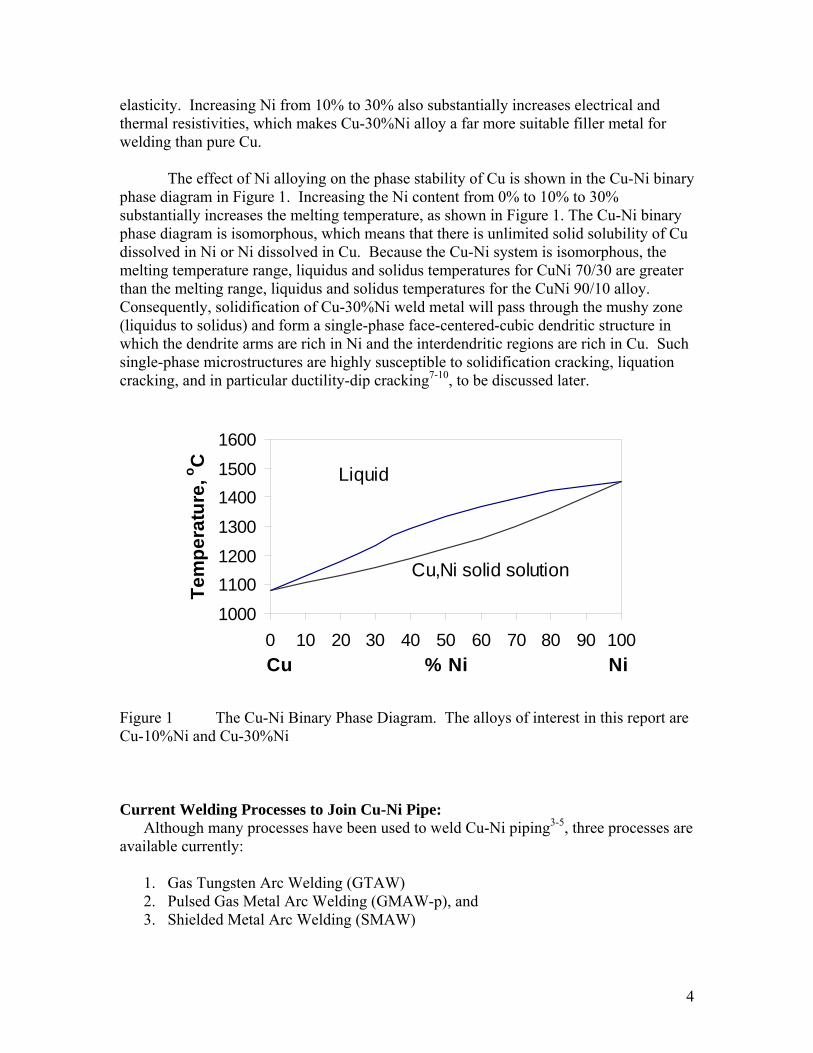
The effect of Ni alloying on the phase stability of Cu is shown in the Cu-Ni binary phase diagram in Figure 1. Increasing the Ni content from 0% to 10% to 30% substantially increases the melting temperature, as shown in Figure 1. The Cu-Ni binary phase diagram is isomorphous, which means that there is unlimited solid solubility of Cu dissolved in Ni or Ni dissolved in Cu. Because the Cu-Ni system is isomorphous, the melting temperature range, liquidus and solidus temperatures for CuNi 70/30 are greater than the melting range, liquidus and solidus temperatures for the CuNi 90/10 alloy. Consequently, solidification of Cu-30%Ni weld metal will pass through the mushy zone (liquidus to solidus) and form a single-phase face-centered-cubic dendritic structure in which the dendrite arms are rich in Ni and the interdendritic regions are rich in Cu. Such single-phase microstructures are highly susceptible to solidification cracking, liquation cracking, and in particular ductility-dip cracking7-10, to be discussed later.
1000
11001200
1300
14001500
1600
0 10 20 30 40 50 60 70 80 90 100Cu % Ni Ni
Tem
pera
ture
, o C
Liquid
Cu,Ni solid solution
Figure 1 The Cu-Ni Binary Phase Diagram. The alloys of interest in this report are Cu-10%Ni and Cu-30%Ni Current Welding Processes to Join Cu-Ni Pipe:
Although many processes have been used to weld Cu-Ni piping3-5, three processes are available currently:
1. Gas Tungsten Arc Welding (GTAW) 2. Pulsed Gas Metal Arc Welding (GMAW-p), and 3. Shielded Metal Arc Welding (SMAW)
5
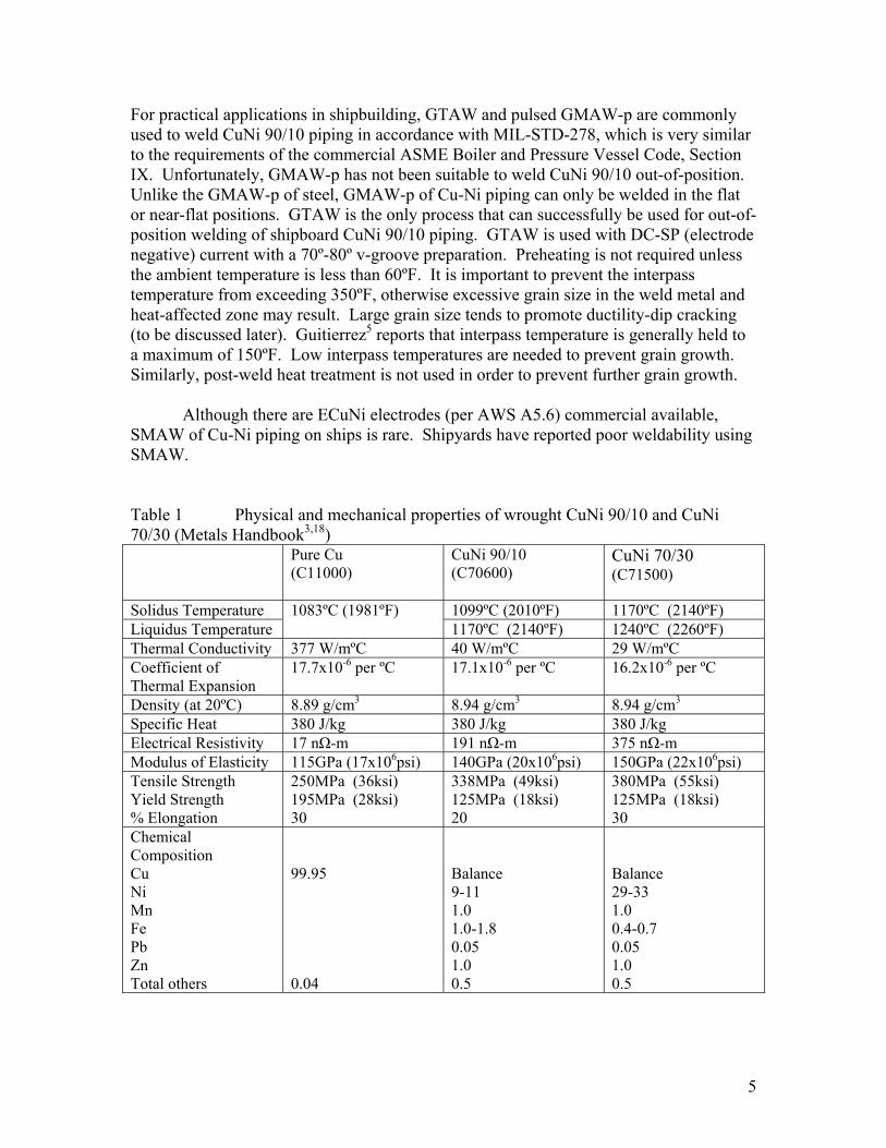
For practical applications in shipbuilding, GTAW and pulsed GMAW-p are commonly used to weld CuNi 90/10 piping in accordance with MIL-STD-278, which is very similar to the requirements of the commercial ASME Boiler and Pressure Vessel Code, Section IX. Unfortunately, GMAW-p has not been suitable to weld CuNi 90/10 out-of-position. Unlike the GMAW-p of steel, GMAW-p of Cu-Ni piping can only be welded in the flat or near-flat positions. GTAW is the only process that can successfully be used for out-of-position welding of shipboard CuNi 90/10 piping. GTAW is used with DC-SP (electrode negative) current with a 70º-80º v-groove preparation. Preheating is not required unless the ambient temperature is less than 60ºF. It is important to prevent the interpass temperature from exceeding 350ºF, otherwise excessive grain size in the weld metal and heat-affected zone may result. Large grain size tends to promote ductility-dip cracking (to be discussed later). Guitierrez5 reports that interpass temperature is generally held to a maximum of 150ºF. Low interpass temperatures are needed to prevent grain growth. Similarly, post-weld heat treatment is not used in order to prevent further grain growth.
Although there are ECuNi electrodes (per AWS A5.6) commercial available, SMAW of Cu-Ni piping on ships is rare. Shipyards have reported poor weldability using SMAW. Table 1 Physical and mechanical properties of wrought CuNi 90/10 and CuNi 70/30 (Metals Handbook3,18)
Pure Cu (C11000)
CuNi 90/10 (C70600)
CuNi 70/30 (C71500)
Solidus Temperature 1099ºC (2010ºF) 1170ºC (2140ºF) Liquidus Temperature
1083ºC (1981ºF) 1170ºC (2140ºF) 1240ºC (2260ºF)
Thermal Conductivity 377 W/mºC 40 W/mºC 29 W/mºC Coefficient of Thermal Expansion
17.7x10⁻⁶ per ºC 17.1x10⁻⁶ per ºC
16.2x10⁻⁶ per ºC
Density (at 20ºC) 8.89 g/cm3 8.94 g/cm3 8.94 g/cm3 Specific Heat 380 J/kg 380 J/kg 380 J/kg Electrical Resistivity 17 nΩ-m 191 nΩ-m 375 nΩ-m Modulus of Elasticity 115GPa (17x106psi) 140GPa (20x106psi) 150GPa (22x106psi) Tensile Strength Yield Strength % Elongation
250MPa (36ksi) 195MPa (28ksi) 30
338MPa (49ksi) 125MPa (18ksi) 20
380MPa (55ksi) 125MPa (18ksi) 30
Chemical Composition Cu Ni Mn Fe Pb Zn Total others
99.95 0.04
Balance 9-11 1.0 1.0-1.8 0.05 1.0 0.5
Balance 29-33 1.0 0.4-0.7 0.05 1.0 0.5
6
Alloying Elements in CuNi 90/10 Piping and CuNi 70/30 Filler Metal: Since the Cu-Ni phase diagram is isomorphous (unlimited solid solubility as
shown if Figure 1), the difference between CuNi 90/10 and CuNi 70/30 piping is measured in the magnitude of solid solution strengthening, melting range, corrosion resistance, electrical, and thermal properties as shown in Table 1. Commonly, the welding of CuNi 90/10 is performed using CuNi 70/30 filler metal. The melting point of pure copper is 1085ºC, but the solidus temperatures for CuNi 90/10 and CuNi 70/30 are 1099ºC and 1171ºC, respectively. Since the filler metal for welding CuNi 90/10 pipe is CuNi 70/30, the higher melting temperature of the filler metal makes it difficult for the welder to deposit welds without undercut. Fortunately, the electrical resistivity of CuNi 70/30 is nearly double that for CuNi 90/10 electrodes and approximately 20 times greater than pure copper, thus facilitating more efficient melt-off rate of the CuNi 70/30 electrode.
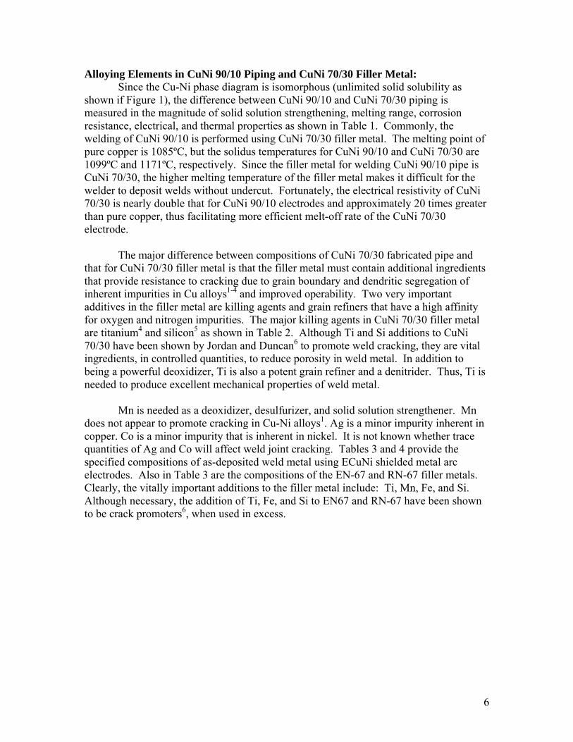
The major difference between compositions of CuNi 70/30 fabricated pipe and that for CuNi 70/30 filler metal is that the filler metal must contain additional ingredients that provide resistance to cracking due to grain boundary and dendritic segregation of inherent impurities in Cu alloys1-4 and improved operability. Two very important additives in the filler metal are killing agents and grain refiners that have a high affinity for oxygen and nitrogen impurities. The major killing agents in CuNi 70/30 filler metal are titanium4 and silicon5 as shown in Table 2. Although Ti and Si additions to CuNi 70/30 have been shown by Jordan and Duncan6 to promote weld cracking, they are vital ingredients, in controlled quantities, to reduce porosity in weld metal. In addition to being a powerful deoxidizer, Ti is also a potent grain refiner and a denitrider. Thus, Ti is needed to produce excellent mechanical properties of weld metal.
Mn is needed as a deoxidizer, desulfurizer, and solid solution strengthener. Mn does not appear to promote cracking in Cu-Ni alloys1. Ag is a minor impurity inherent in copper. Co is a minor impurity that is inherent in nickel. It is not known whether trace quantities of Ag and Co will affect weld joint cracking. Tables 3 and 4 provide the specified compositions of as-deposited weld metal using ECuNi shielded metal arc electrodes. Also in Table 3 are the compositions of the EN-67 and RN-67 filler metals. Clearly, the vitally important additions to the filler metal include: Ti, Mn, Fe, and Si. Although necessary, the addition of Ti, Fe, and Si to EN67 and RN-67 have been shown to be crack promoters6, when used in excess.
7
Table 2 Alloying elements and common impurities affecting weld cracking of CuNi 90/10 piping using CuNi 70/30 filler metal Element Effect on Weld
Joint Cracking Susceptibility
Purpose for Alloying
Ni Mn Fe Si Ti
Alloying alloying alloying alloying alloying
Increases Decreases Increases Increases Increases
Strength & corrosion resistance Desulfurizer & deoxidizer Deoxidizer & corrosion resistance Deoxidizer, fluxing, reduces porosity Grain refiner, deoxidizer, denitrider reduces porosity, & improves fluidity
C Pb, Bi, Sn Te, Se Ag, Co
Impurity Impurities Impurities Impurities Impurity
Complex Increases Increases Increases Not harmful
Forms compounds with Fe and Ti None None None (but does improve machinability) None
Table 3 Comparison of compositions for: ECuNi (as-deposited SMAW), ERCuNi (wire GMAW), EN67 (wire GMAW), and RN67 (rod GTAW) Elements
ECuNi ANSI/AWS A5.6 As-Deposited SMAW
ERCuNi ANSI/AWS A5.7 Wire GMAW
EN67 & RN67 MIL-E-21562E(SH) Wire & Rod GMAW & GTAW
Cu Ni + Co C Zn Sn Mn Fe Si P S Pb Ti Total other elements
Balance 29.0 – 33.0 - f f 1.0 – 2.5 0.4 – 0.75 0.5 0.020 0.015 0.02 0.50 0.50
Balance 29.0 – 32.0 - - - 1.00 0.40 – 0.75 0.25 0.02 0.01 0.02 0.20 – 0.50 0.50
Balance 29.0 – 32.0 0.04 1.00 0.4 – 0.7 0.25 0.020 0.015 0.010 0.20 – 0.50 0.50
UNS Number W60715 C71580 f . Those elements must be included in total of other elements
8
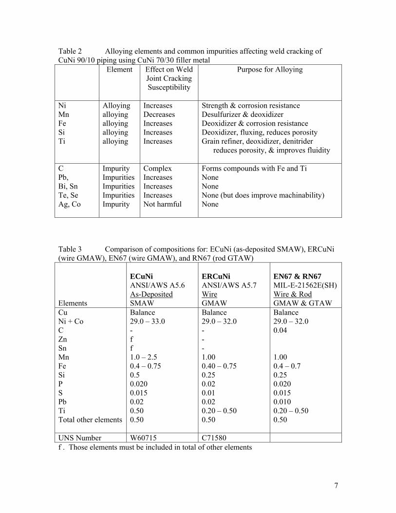
Table 4 Weld metal mechanical properties required by governing specification Properties
ECuNi ANSI/AWS A5.6 As-Deposited SMAW
ERCuNi ANSI/AWS A5.7 Wire GMAW
EN67 & RN67 MIL-E-21562E(SH) Wire & Rod GMAW & GTAW
Tensile Strength Yield Strength % Elongation Side Bend Test
350MPa (50ksi) n/a 20 n/a
n/a: 350MPa (50ksi) n/a n/a n/a
350MPa (50ksi) n/a 30 Yes
Solidification Cracking and HAZ Liquation Cracking in Cu-Ni Weldments:
As mentioned earlier, the three types of hot cracking that have been experienced by many Naval and commercial fabricators, who weld CuNi 90/10 with CuNi 70/30 filler metal, include: solidification cracking in the weld metal, liquation cracking in the HAZ, and ductility dip cracking in the HAZ of previously deposited weld metal.
Many investigators have studied the solidification cracking and liquation cracking of Cu-Ni alloys. Clearly, the three primary factors promoting solidification cracking in the as-deposited weld metal and liquation cracking in the HAZ are:
• Wide solidus-liquidus temperature range, • Sufficient tensile stress during solidification, and • Composition susceptible to cracking.
Solidification cracking is always a potential problem particularly under conditions of
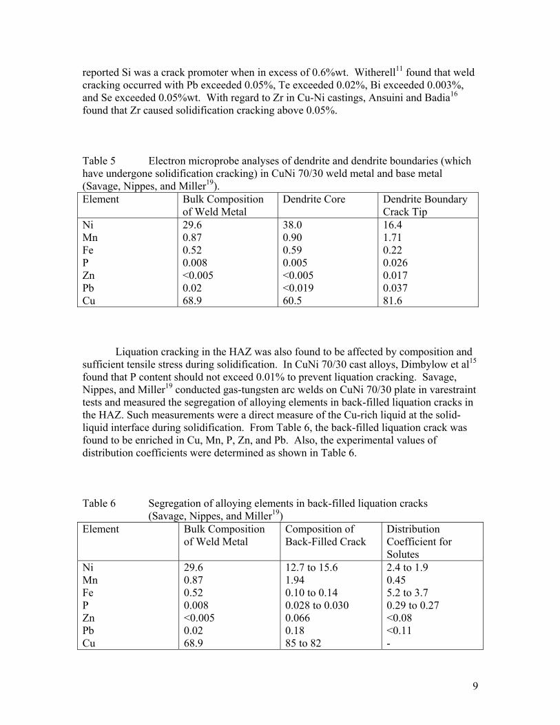
high tensile restraint, because of the significant temperature range between the solidus and liquidus for both the CuNi 70/30 filler metal and the CuNi 90/10 base metal. For example, the solidus/liquidus temperature range for CuNi 70/30 is 79ºC. As a result, the solidification substructure is always dendritic with the dendrite cores rich in Ni and the interdendritic spaces rich in Cu17,19. Savage, Nippes and Miller19 have found the cores of CuNi 70/30 weld metal typically contained 38%Ni and the interdendritic space contained 16%Ni (see Table 5). Even more detrimental to cracking was the effect of insoluble impurities that formed low melting films between dendrites and within grain boundaries17.
In addition to the inherent solidification behavior of CuNi 90/10 and CuNi 70/30 alloys, the following impurity elements were found to increase the susceptibility to solidification cracking: P, Si, Pb, Te, Mn, Zr, and Cr6. The mechanism was presumed to be the augmentation of the solidus/liquidus temperature range. Witherell1 reported that cracking occurred when the P content exceeded 0.02%. Similarly, Lee et al12 reported cracking with P contents over the range 0.005-0.03% by weight. Although Si is a deoxidizer, Vanick13 reports Si promotes cracking in amounts over 0.1%. Paterson14
9
reported Si was a crack promoter when in excess of 0.6%wt. Witherell11 found that weld cracking occurred with Pb exceeded 0.05%, Te exceeded 0.02%, Bi exceeded 0.003%, and Se exceeded 0.05%wt. With regard to Zr in Cu-Ni castings, Ansuini and Badia16 found that Zr caused solidification cracking above 0.05%. Table 5 Electron microprobe analyses of dendrite and dendrite boundaries (which have undergone solidification cracking) in CuNi 70/30 weld metal and base metal (Savage, Nippes, and Miller19). Element Bulk Composition
of Weld Metal Dendrite Core Dendrite Boundary
Crack Tip Ni Mn Fe P Zn Pb Cu
29.6 0.87 0.52 0.008 <0.005 0.02 68.9
38.0 0.90 0.59 0.005 <0.005 <0.019 60.5
16.4 1.71 0.22 0.026 0.017 0.037 81.6
Liquation cracking in the HAZ was also found to be affected by composition and sufficient tensile stress during solidification. In CuNi 70/30 cast alloys, Dimbylow et al15 found that P content should not exceed 0.01% to prevent liquation cracking. Savage, Nippes, and Miller19 conducted gas-tungsten arc welds on CuNi 70/30 plate in varestraint tests and measured the segregation of alloying elements in back-filled liquation cracks in the HAZ. Such measurements were a direct measure of the Cu-rich liquid at the solid-liquid interface during solidification. From Table 6, the back-filled liquation crack was found to be enriched in Cu, Mn, P, Zn, and Pb. Also, the experimental values of distribution coefficients were determined as shown in Table 6. Table 6 Segregation of alloying elements in back-filled liquation cracks
(Savage, Nippes, and Miller19) Element Bulk Composition
of Weld Metal Composition of Back-Filled Crack
Distribution Coefficient for Solutes
Ni Mn Fe P Zn Pb Cu
29.6 0.87 0.52 0.008 <0.005 0.02 68.9
12.7 to 15.6 1.94 0.10 to 0.14 0.028 to 0.030 0.066 0.18 85 to 82
2.4 to 1.9 0.45 5.2 to 3.7 0.29 to 0.27 <0.08 <0.11 -
10
Ductility Dip Cracking: Ductility dip cracking (DDC) is a solid state problem that takes place at elevated
temperatures above the half-melting temperature (0.5Tm in degrees Kelvin), while being subjected to sufficient tensile loading or solidification shrinkage stresses from subsequent weld passes. DDC is most commonly found in mult-pass welding because of the simultaneous presence of ample residual tensile stress and short-term elevated temperature thermal cycling with each subsequent welding pass. This explains why cracks due to DDC typically were observed in the HAZ below the final pass. In fact, since tensile straining during weld reheating within the DDC-susceptible temperature range commonly occurred in previous passes of mult-pass welds, all of the previous passes have been observed to be susceptible to DDC while the final cap pass was sound28. As a result, DDC was usually reported to be subsurface, such that surface inspection techniques were not adequate to detect DDC. However, ultrasonic techniques and destructive test methods such as the side bend test have revealed DDC10.
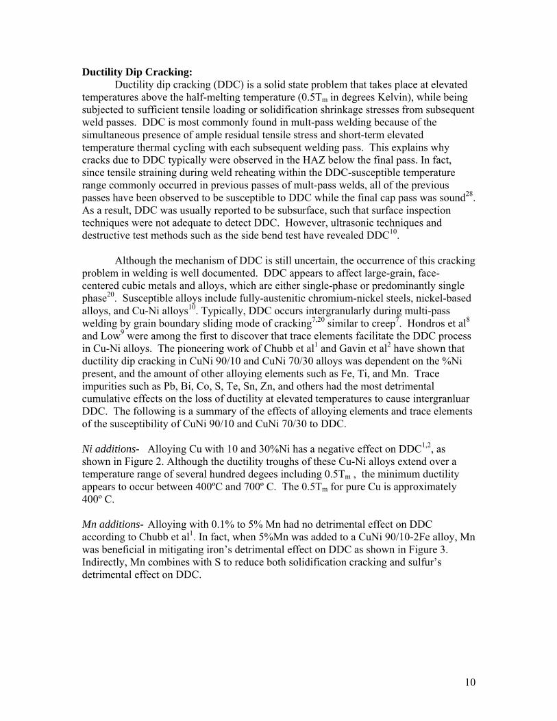
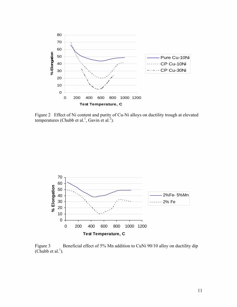
Although the mechanism of DDC is still uncertain, the occurrence of this cracking problem in welding is well documented. DDC appears to affect large-grain, face-centered cubic metals and alloys, which are either single-phase or predominantly single phase20. Susceptible alloys include fully-austenitic chromium-nickel steels, nickel-based alloys, and Cu-Ni alloys10. Typically, DDC occurs intergranularly during multi-pass welding by grain boundary sliding mode of cracking7,20 similar to creep7. Hondros et al8 and Low9 were among the first to discover that trace elements facilitate the DDC process in Cu-Ni alloys. The pioneering work of Chubb et al1 and Gavin et al2 have shown that ductility dip cracking in CuNi 90/10 and CuNi 70/30 alloys was dependent on the %Ni present, and the amount of other alloying elements such as Fe, Ti, and Mn. Trace impurities such as Pb, Bi, Co, S, Te, Sn, Zn, and others had the most detrimental cumulative effects on the loss of ductility at elevated temperatures to cause intergranluar DDC. The following is a summary of the effects of alloying elements and trace elements of the susceptibility of CuNi 90/10 and CuNi 70/30 to DDC. Ni additions- Alloying Cu with 10 and 30%Ni has a negative effect on DDC1,2, as shown in Figure 2. Although the ductility troughs of these Cu-Ni alloys extend over a temperature range of several hundred degees including 0.5Tm , the minimum ductility appears to occur between 400ºC and 700º C. The 0.5Tm for pure Cu is approximately 400º C. Mn additions- Alloying with 0.1% to 5% Mn had no detrimental effect on DDC according to Chubb et al1. In fact, when 5%Mn was added to a CuNi 90/10-2Fe alloy, Mn was beneficial in mitigating iron’s detrimental effect on DDC as shown in Figure 3. Indirectly, Mn combines with S to reduce both solidification cracking and sulfur’s detrimental effect on DDC.
11
0
10
20
30
40
50
60
70
80
0 200 400 600 800 1000 1200
Test Temperature, C
% E
long
atio
nPure Cu-10NiCP Cu-10NiCP Cu-30Ni
Figure 2 Effect of Ni content and purity of Cu-Ni alloys on ductility trough at elevated temperatures (Chubb et al.1, Gavin et al.2).
010203040506070
0 200 400 600 800 1000 1200
Test Temperature, C
% E
long
atio
n
2%Fe- 5%Mn2% Fe
Figure 3 Beneficial effect of 5% Mn addition to CuNi 90/10 alloy on ductility dip (Chubb et al.1).
12
0
10
20
30
40
50
60
70
0 200 400 600 800 1000 1200
Test Temperature, C
% E
long
atio
n
0.1% Fe2% Fe5% Fe
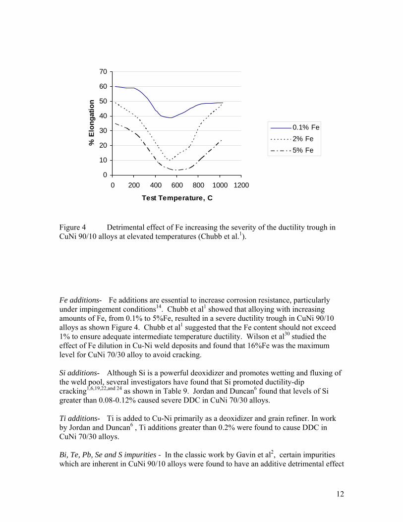
Figure 4 Detrimental effect of Fe increasing the severity of the ductility trough in CuNi 90/10 alloys at elevated temperatures (Chubb et al.1). Fe additions- Fe additions are essential to increase corrosion resistance, particularly under impingement conditions14. Chubb et al1 showed that alloying with increasing amounts of Fe, from 0.1% to 5%Fe, resulted in a severe ductility trough in CuNi 90/10 alloys as shown Figure 4. Chubb et al1 suggested that the Fe content should not exceed 1% to ensure adequate intermediate temperature ductility. Wilson et al30 studied the effect of Fe dilution in Cu-Ni weld deposits and found that 16%Fe was the maximum level for CuNi 70/30 alloy to avoid cracking. Si additions- Although Si is a powerful deoxidizer and promotes wetting and fluxing of the weld pool, several investigators have found that Si promoted ductility-dip cracking1,6,19,22,and 24 as shown in Table 9. Jordan and Duncan6 found that levels of Si greater than 0.08-0.12% caused severe DDC in CuNi 70/30 alloys. Ti additions- Ti is added to Cu-Ni primarily as a deoxidizer and grain refiner. In work by Jordan and Duncan6 , Ti additions greater than 0.2% were found to cause DDC in CuNi 70/30 alloys. Bi, Te, Pb, Se and S impurities - In the classic work by Gavin et al2, certain impurities which are inherent in CuNi 90/10 alloys were found to have an additive detrimental effect
13
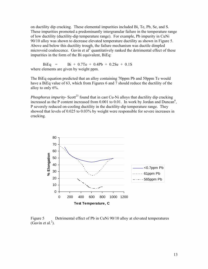
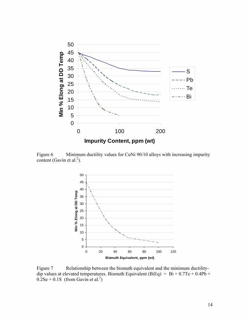
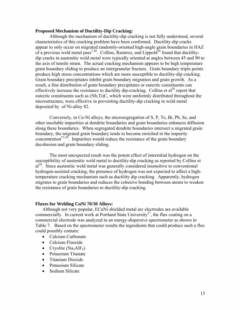
on ductility dip cracking. These elemental impurities included Bi, Te, Pb, Se, and S. These impurities promoted a predominantly intergranular failure in the temperature range of low ductility (ductility-dip temperature range). For example, Pb impurity in CuNi 90/10 alloy was shown to decrease elevated temperature ductility as shown in Figure 5. Above and below this ductility trough, the failure mechanism was ductile dimpled microvoid coalescence. Gavin et al2 quantitatively ranked the detrimental effect of these impurities in the form of the Bi equivalent, BiEq:
BiEq = Bi + 0.7Te + 0.4Pb + 0.2Se + 0.1S where elements are given by weight ppm. The BiEq equation predicted that an alloy containing 70ppm Pb and 50ppm Te would have a BiEq value of 63, which from Figures 6 and 7 should reduce the ductility of the alloy to only 6%. Phosphorus impurity- Scott23 found that in cast Cu-Ni alloys that ductility dip cracking increased as the P content increased from 0.001 to 0.01. In work by Jordan and Duncan6, P severely reduced on-cooling ductility in the ductility-dip temperature range. They showed that levels of 0.025 to 0.03% by weight were responsible for severe increases in cracking.
0
10
20
30
40
50
60
70
80
0 200 400 600 800 1000 1200
Test Temperature, C
% E
long
atio
n
<0.7ppm Pb61ppm Pb565ppm Pb
Figure 5 Detrimental effect of Pb in CuNi 90/10 alloy at elevated temperatures (Gavin et al.2).
14
05
101520253035404550
0 100 200
Impurity Content, ppm (wt)
Min
% E
long
at D
D T
emp
SPbTeBi
Figure 6 Minimum ductility values for CuNi 90/10 alloys with increasing impurity content (Gavin et al.2).
0
5
10
15
20
25
30
35
40
45
50
0 20 40 60 80 100 120
Bismuth Equivalent, ppm (wt)
Min
% E
long
at D
D Te
mp
Figure 7 Relationship between the bismuth equivalent and the minimum ductility-dip values at elevated temperatures. Bismuth Equivalent (BiEq) = Bi + 0.7Te + 0.4Pb + 0.2Se + 0.1S (from Gavin et al.2)
15
Proposed Mechanism of Ductility-Dip Cracking: Although the mechanism of ductility-dip cracking is not fully understood, several
characteristics of this cracking problem have been confirmed. Ductility-dip cracks appear to only occur on migrated randomly-oriented high-angle grain boundaries in HAZ of a previous weld metal pass7,20. Collins, Ramirez, and Lippold20 found that ductility-dip cracks in austenitic weld metal were typically oriented at angles between 45 and 90 to the axis of tensile strain. The actual cracking mechanism appears to be high temperature grain boundary sliding to produce an intergranular fracture. Grain boundary triple points produce high stress concentrations which are more susceptible to ductility-dip cracking. Grain boundary precipitates inhibit grain boundary migration and grain growth. As a result, a fine distribution of grain boundary precipitates or eutectic constituents can effectively increase the resistance to ductility dip-cracking. Collins et al20 report that eutectic constituents such as (Nb,Ti)C, which were uniformly distributed throughout the microstructure, were effective in preventing ductility-dip cracking in weld metal deposited by of Ni-alloy 82.
Conversely, in Cu-Ni alloys, the microsegregation of S, P, Te, Bi, Pb, Se, and other insoluble impurities at dendrite boundaries and grain boundaries enhances diffusion along these boundaries. When segregated dendrite boundaries intersect a migrated grain boundary, the migrated grain boundary tends to become enriched in the impurity concentration27-29. Impurities would reduce the resistance of the grain boundary decohesion and grain boundary sliding.
The most unexpected result was the potent effect of interstitial hydrogen on the susceptibility of austenitic weld metal to ductility-dip cracking as reported by Collins et al20. Since austenitic weld metal was generally considered insensitive to conventional hydrogen-assisted cracking, the presence of hydrogen was not expected to affect a high-temperature cracking mechanism such as ductility dip cracking. Apparently, hydrogen migrates to grain boundaries and reduces the cohesive bonding between atoms to weaken the resistance of grain boundaries to ductility-dip cracking. Fluxes for Welding CuNi 70/30 Alloys:
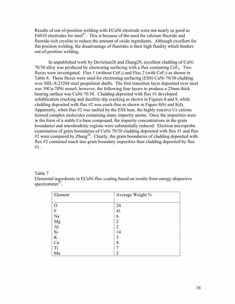
Although not very popular, ECuNi shielded metal arc electrodes are available commercially. In current work at Portland State University27, the flux coating on a commercial electrode was analyzed in an energy-dispersive spectrometer as shown in Table 7. Based on the spectrometer results the ingredients that could produce such a flux could possibly contain:
• Calcium Carbonate • Calcium Fluoride • Cryolite (Na3AlF6) • Potassium Titanate • Titanium Dioxide • Potassium Silicate • Sodium Silicate
16
Results of out-of-position welding with ECuNi electrode were not nearly as good as E6010 electrodes for steel27. This is because of the need for calcium fluoride and fluoride-rich cryolite to reduce the amount of oxide ingredients. Although excellent for flat position welding, the disadvantage of fluorides is their high fluidity which hinders out-of-position welding.
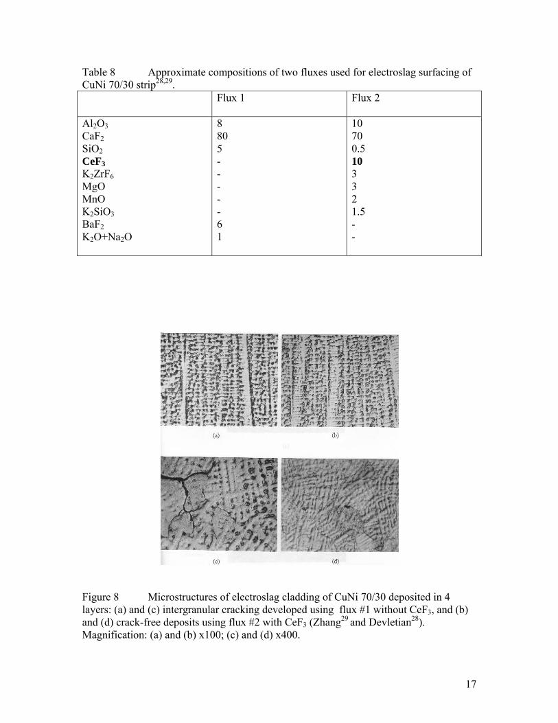
In unpublished work by Devletian28 and Zhang29, excellent cladding of CuNi 70/30 alloy was produced by electroslag surfacing with a flux containing CeF3. Two fluxes were investigated: Flux 1 (without CeF3) and Flux 2 (with CeF3) as shown in Table 8. These fluxes were used for electroslag surfacing (ESS) CuNi 70/30 cladding over MIL-S-23284 steel propulsion shafts. The first transition layer deposited over steel was 30Cu-70Ni monel; however, the following four layers to produce a 25mm thick bearing surface was CuNi 70/30. Cladding deposited with flux #1 developed solidification cracking and ductility-dip cracking as shown in Figures 8 and 9, while cladding deposited with flux #2 was crack-free as shown in Figure 8(b) and 8(d). Apparently, when flux #2 was melted by the ESS heat, the highly reactive Ce cations formed complex molecules containing many impurity atoms. Once the impurities were in the form of a stable Ce-base compound, the impurity concentrations in the grain boundaries and interdendritic regions were substantially reduced. Electron microprobe examination of grain boundaries of CuNi 70/30 cladding deposited with flux #1 and flux #2 were compared by Zhang29. Clearly, the grain boundaries of cladding deposited with flux #2 contained much less grain boundary impurities than cladding deposited by flux #1. Table 7 Elemental ingredients in ECuNi flux coating based on results from energy-dispersive spectrometer27.
Element Average Weight %
O 24 F 41 Na 6 Mg 2 Al 2 Si 14 K 3 Ca 8 Ti 7 Mn 2
17
Table 8 Approximate compositions of two fluxes used for electroslag surfacing of CuNi 70/30 strip28,29.
Flux 1 Flux 2
Al2O3 CaF2 SiO2 CeF3 K2ZrF6 MgO MnO K2SiO3 BaF2 K2O+Na2O
8 80 5 - - - - - 6 1
10 70 0.5 10 3 3 2 1.5 - -
Figure 8 Microstructures of electroslag cladding of CuNi 70/30 deposited in 4 layers: (a) and (c) intergranular cracking developed using flux #1 without CeF3, and (b) and (d) crack-free deposits using flux #2 with CeF3 (Zhang29 and Devletian28). Magnification: (a) and (b) x100; (c) and (d) x400.
18
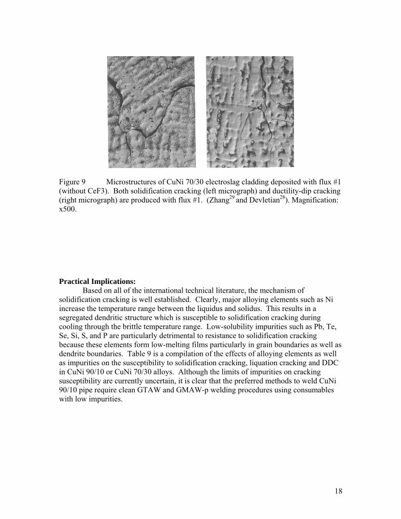
Figure 9 Microstructures of CuNi 70/30 electroslag cladding deposited with flux #1 (without CeF3). Both solidification cracking (left micrograph) and ductility-dip cracking (right micrograph) are produced with flux #1. (Zhang29 and Devletian28). Magnification: x500. Practical Implications:
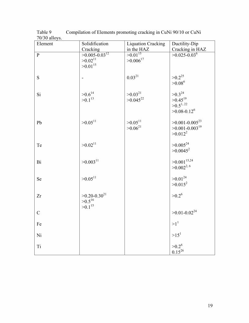
Based on all of the international technical literature, the mechanism of solidification cracking is well established. Clearly, major alloying elements such as Ni increase the temperature range between the liquidus and solidus. This results in a segregated dendritic structure which is susceptible to solidification cracking during cooling through the brittle temperature range. Low-solubility impurities such as Pb, Te, Se, Si, S, and P are particularly detrimental to resistance to solidification cracking because these elements form low-melting films particularly in grain boundaries as well as dendrite boundaries. Table 9 is a compilation of the effects of alloying elements as well as impurities on the susceptibility to solidification cracking, liquation cracking and DDC in CuNi 90/10 or CuNi 70/30 alloys. Although the limits of impurities on cracking susceptibility are currently uncertain, it is clear that the preferred methods to weld CuNi 90/10 pipe require clean GTAW and GMAW-p welding procedures using consumables with low impurities.
19
Table 9 Compilation of Elements promoting cracking in CuNi 90/10 or CuNi 70/30 alloys. Element Solidification
Cracking Liquation Cracking in the HAZ
Ductility-Dip Cracking in HAZ
P S Si Pb Te Bi Se Zr C Fe Ni Ti
>0.005-0.0312 >0.0211 >0.0115 - >0.614 >0.113 >0.0511 >0.0211 >0.00311 >0.0511 >0.20-0.3021 >0.516 >0.115
>0.0115 >0.00617 0.0321 >0.0321 >0.04522 >0.0511 >0.0621
>0.025-0.036 >0.225 >0.086 >0.324 >0.4519 >0.51, 22 >0.08-0.126 >0.001-0.00523 >0.001-0.00319 >0.0122 >0.00524 >0.00452 >0.00115,24 >0.0022, 6 >0.0124 >0.0152 >0.26 >0.01-0.0224 >11 >151 >0.26 0.1526
20
RESEARCH TEAM
The research collaboration for this one-year investigation involved four groups
including: (1) Portland State University, (2) NASSCO shipyard, (3) Fabricator “A”, and (4) Fabricator “B”.
Portland State University was the prime contractor and NASSCO was the subcontractor. Portland State University coordinated the project tasks and provided the metallurgical evaluation and mechanical testing of experimental welds. NASSCO provided the operability assessment for each experimental CuNi 70/30 flux cored electrode. Fabricators A and B developed the flux chemistries needed to produce an all-position flux cored electrode to weld CuNi 90/10 pipe. For convenience, the experimental flux cored electrodes were called: “EN67T-1”.
EXPERIMENTAL PROCEDURE Fabrication of Experimental Flux Cored Electrodes:
Using their many years of practical experience formulating flux chemistries and designing flux cored electrodes, Fabricator A and Fabricator B provided experimental EN67T-1 flux cored electrodes for welding CuNi 90/10 in this study. The chief welding engineer of NASSCO had mock-ups of pipe joints constructed and shipped to Fabricator A and Fabricator B to facilitate trial pipe welds. Each fabricator evaluated their own experimental flux cored electrodes by welding sections of the mock-up pipe joints. Although many iterations of EN67T-1 flux cored filler metal compositions were developed and tested in the fabricators’ laboratories, a total of 4 experimental flux cored electrodes were deemed good enough by Fabricators A and B to be shipped to and tested for operability by NASSCO. After testing for operability at NASSCO, these flux cored test weld joints were then shipped to Portland State University for metallurgical and mechanical property evaluation.
For purposes of this investigation, the experimental flux cored electrodes were identified as A-3, A-5, and A-6 from Fabricator “A”, and B3 from Fabricator “B”. An explanation of this identification system is provided in Table 10.
21
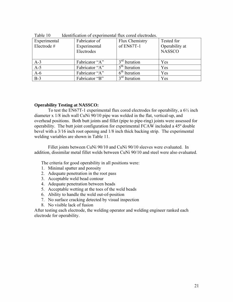
Table 10 Identification of experimental flux cored electrodes. Experimental Electrode #
Fabricator of Experimental Electrodes
Flux Chemistry of EN67T-1
Tested for Operability at NASSCO
A-3 Fabricator “A” 3rd Iteration Yes A-5 Fabricator “A” 5th Iteration Yes A-6 Fabricator “A” 6th Iteration Yes B-3 Fabricator “B” 3rd Iteration Yes Operability Testing at NASSCO:
To test the EN67T-1 experimental flux cored electrodes for operability, a 6½ inch diameter x 1/8 inch wall CuNi 90/10 pipe was welded in the flat, vertical-up, and overhead positions. Both butt joints and fillet (pipe to pipe-ring) joints were assessed for operability. The butt joint configuration for experimental FCAW included a 45º double bevel with a 3/16 inch root opening and 1/8 inch thick backing strip. The experimental welding variables are shown in Table 11.
Fillet joints between CuNi 90/10 and CuNi 90/10 sleeves were evaluated. In addition, dissimilar metal fillet welds between CuNi 90/10 and steel were also evaluated.
The criteria for good operability in all positions were: 1. Minimal spatter and porosity 2. Adequate penetration in the root pass 3. Acceptable weld bead contour 4. Adequate penetration between beads 5. Acceptable wetting at the toes of the weld beads 6. Ability to handle the weld out-of-position 7. No surface cracking detected by visual inspection 8. No visible lack of fusion
After testing each electrode, the welding operator and welding engineer ranked each electrode for operability.
22
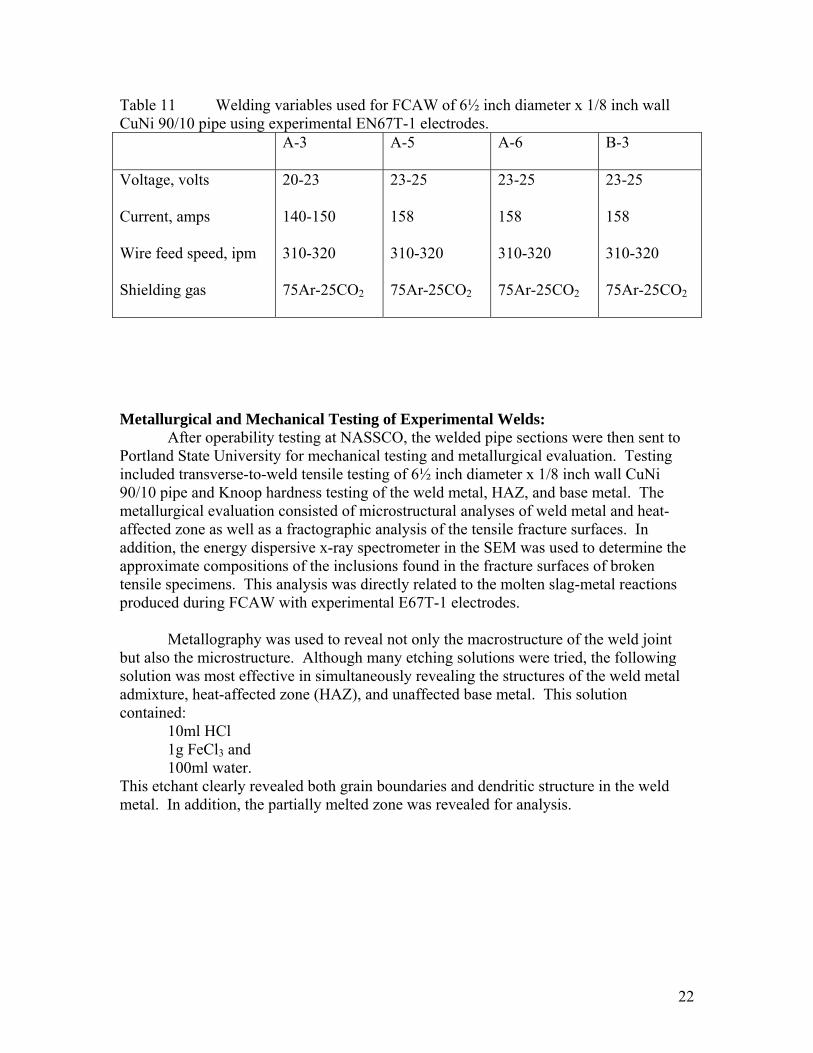
Table 11 Welding variables used for FCAW of 6½ inch diameter x 1/8 inch wall CuNi 90/10 pipe using experimental EN67T-1 electrodes.
A-3 A-5 A-6 B-3
Voltage, volts Current, amps Wire feed speed, ipm Shielding gas
20-23 140-150 310-320 75Ar-25CO2
23-25 158 310-320 75Ar-25CO2
23-25 158 310-320 75Ar-25CO2
23-25 158 310-320 75Ar-25CO2
Metallurgical and Mechanical Testing of Experimental Welds:
After operability testing at NASSCO, the welded pipe sections were then sent to Portland State University for mechanical testing and metallurgical evaluation. Testing included transverse-to-weld tensile testing of 6½ inch diameter x 1/8 inch wall CuNi 90/10 pipe and Knoop hardness testing of the weld metal, HAZ, and base metal. The metallurgical evaluation consisted of microstructural analyses of weld metal and heat-affected zone as well as a fractographic analysis of the tensile fracture surfaces. In addition, the energy dispersive x-ray spectrometer in the SEM was used to determine the approximate compositions of the inclusions found in the fracture surfaces of broken tensile specimens. This analysis was directly related to the molten slag-metal reactions produced during FCAW with experimental E67T-1 electrodes.
Metallography was used to reveal not only the macrostructure of the weld joint but also the microstructure. Although many etching solutions were tried, the following solution was most effective in simultaneously revealing the structures of the weld metal admixture, heat-affected zone (HAZ), and unaffected base metal. This solution contained:
10ml HCl 1g FeCl3 and 100ml water.
This etchant clearly revealed both grain boundaries and dendritic structure in the weld metal. In addition, the partially melted zone was revealed for analysis.
23
RESULTS AND DISCUSSION Current Practice of GTAW and GMAW-p of CuNi 90/10 Pipe:
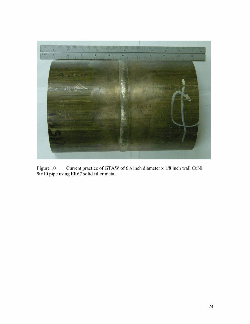
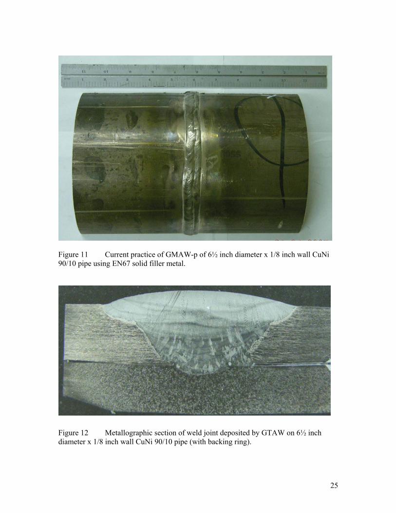
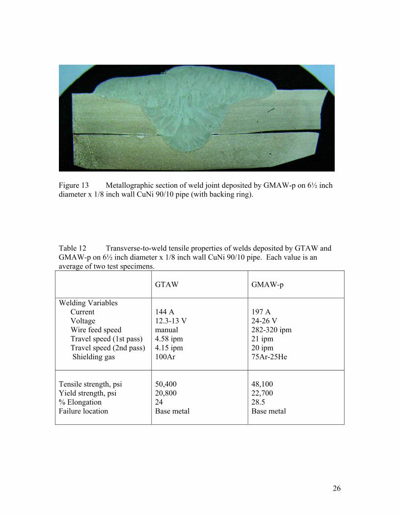
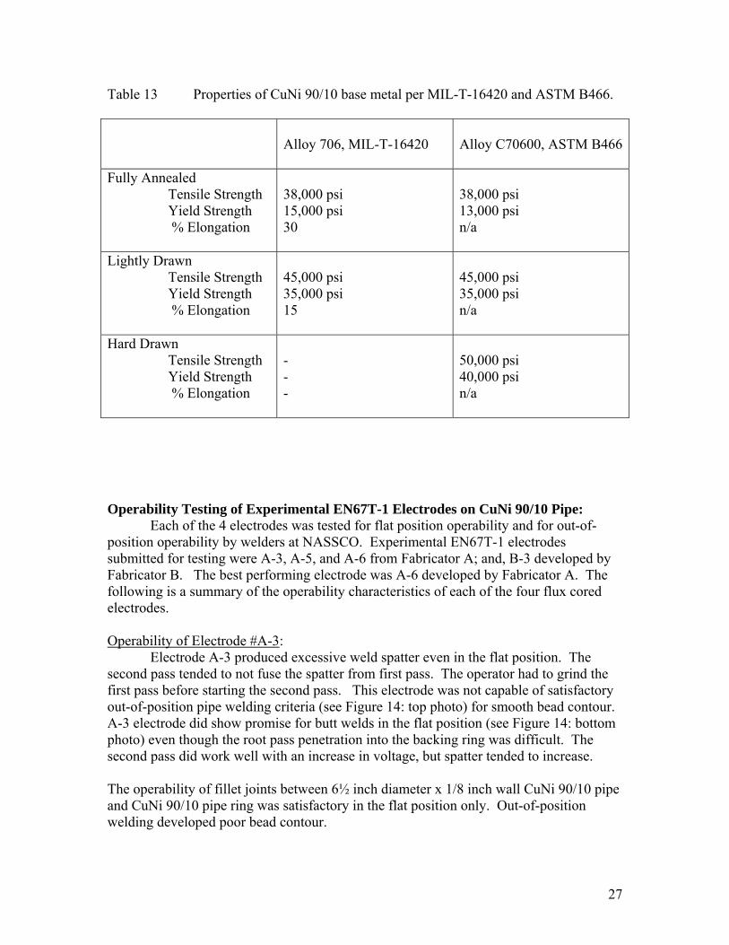
The current state-of-the-art of welding CuNi 90/10 pipe for Naval ships is to use GTAW for all out-of-position welding and GMAW-p for more productive flat position welds. Figures 10 and 11 show the excellent-quality welds deposited on 6½ inch diameter x 1/8 inch wall CuNi 90/10 pipe by GTAW and GMAW-p, respectively. Welding variables for both GTAW and GMAW-p are provided in Table 12. These welds were found to be sound and spatter-free. Metallographic sections of the welds deposited by GTAW and GMAW-p are shown in Figures 12 and 13, respectively.
Transverse-to-weld tensile tests were conducted on the reference welds deposited by GTAW (Figure 10) and GMAW-p (Figure 11). In every case, the failure occurred outside the weld in the unaffected base metal. The mechanical properties of weld joints deposited by GTAW and GMAW-p are provided in Table 12. Since the RN67 and EN67 filler metals contained CuNi 70/30 while the base metal contained only 10Ni, the as-deposited weld metal admixture was stronger than the base metal. The added strength of the weld metal was due to solid solution strengthening produced by the 30%Ni in the filler metal. As a result, the transverse tensile properties were dependent upon those of the base metal. From Table 12, the yield strength values for the weld joints deposited by GTAW and GMAW-p were 20,800 and 22,700 psi, respectively.
From Table 13, CuNi 90/10 pipe and tubing are commercially available in three
strength levels: 1. Fully annealed 2. Lightly drawn 3. Hard drawn
From this table, weld joints would be expected to fail in the base metal if the CuNi 90/10 pipe were fully annealed or lightly drawn. Even the hard drawn CuNi 90/10 may fail in the heat-affected zone (HAZ) due to softening caused by recrystallization and grain growth of the cold drawn microstructure produced by the heat of welding.
24
Figure 10 Current practice of GTAW of 6½ inch diameter x 1/8 inch wall CuNi 90/10 pipe using ER67 solid filler metal.
25
Figure 11 Current practice of GMAW-p of 6½ inch diameter x 1/8 inch wall CuNi 90/10 pipe using EN67 solid filler metal.
Figure 12 Metallographic section of weld joint deposited by GTAW on 6½ inch diameter x 1/8 inch wall CuNi 90/10 pipe (with backing ring).
26
Figure 13 Metallographic section of weld joint deposited by GMAW-p on 6½ inch diameter x 1/8 inch wall CuNi 90/10 pipe (with backing ring). Table 12 Transverse-to-weld tensile properties of welds deposited by GTAW and GMAW-p on 6½ inch diameter x 1/8 inch wall CuNi 90/10 pipe. Each value is an average of two test specimens.
GTAW
GMAW-p
Welding Variables Current Voltage Wire feed speed Travel speed (1st pass) Travel speed (2nd pass) Shielding gas
144 A 12.3-13 V manual 4.58 ipm 4.15 ipm 100Ar
197 A 24-26 V 282-320 ipm 21 ipm 20 ipm 75Ar-25He
Tensile strength, psi Yield strength, psi % Elongation Failure location
50,400 20,800 24 Base metal
48,100 22,700 28.5 Base metal
27
Table 13 Properties of CuNi 90/10 base metal per MIL-T-16420 and ASTM B466.
Alloy 706, MIL-T-16420
Alloy C70600, ASTM B466
Fully Annealed Tensile Strength Yield Strength % Elongation
38,000 psi 15,000 psi 30
38,000 psi 13,000 psi n/a
Lightly Drawn Tensile Strength Yield Strength % Elongation
45,000 psi 35,000 psi 15
45,000 psi 35,000 psi n/a
Hard Drawn Tensile Strength Yield Strength % Elongation
- - -
50,000 psi 40,000 psi n/a
Operability Testing of Experimental EN67T-1 Electrodes on CuNi 90/10 Pipe:
Each of the 4 electrodes was tested for flat position operability and for out-of-position operability by welders at NASSCO. Experimental EN67T-1 electrodes submitted for testing were A-3, A-5, and A-6 from Fabricator A; and, B-3 developed by Fabricator B. The best performing electrode was A-6 developed by Fabricator A. The following is a summary of the operability characteristics of each of the four flux cored electrodes. Operability of Electrode #A-3:
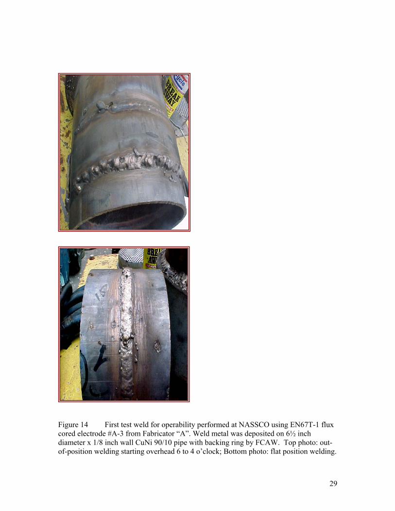
Electrode A-3 produced excessive weld spatter even in the flat position. The second pass tended to not fuse the spatter from first pass. The operator had to grind the first pass before starting the second pass. This electrode was not capable of satisfactory out-of-position pipe welding criteria (see Figure 14: top photo) for smooth bead contour. A-3 electrode did show promise for butt welds in the flat position (see Figure 14: bottom photo) even though the root pass penetration into the backing ring was difficult. The second pass did work well with an increase in voltage, but spatter tended to increase. The operability of fillet joints between 6½ inch diameter x 1/8 inch wall CuNi 90/10 pipe and CuNi 90/10 pipe ring was satisfactory in the flat position only. Out-of-position welding developed poor bead contour.
28
Operability of Electrode #A-5:
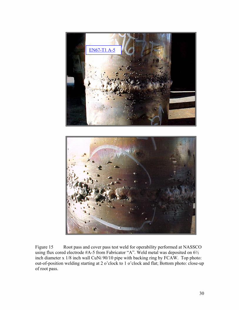
Figure 15 shows the root pass and cover pass of test weld using flux cored electrode #A-5 from Fabricator “A”. Weld metal was deposited on 6½ inch diameter x 1/8 inch wall CuNi 90/10 pipe with backing a ring by FCAW out-of-position starting at 2 o’clock to 1 o’clock and flat. The electrode performed well except for excessive spatter. In butt joints, it was difficult to reach the backing ring causing incomplete penetration. The #A-5 electrode worked best in the flat position. But, out-of-position welding with #A-5 was unsatisfactory due to spatter, porosity and bead contour. Fillet welds were smoother than butt welds, but spatter still was unacceptable. Operability of Electrode #A-6:
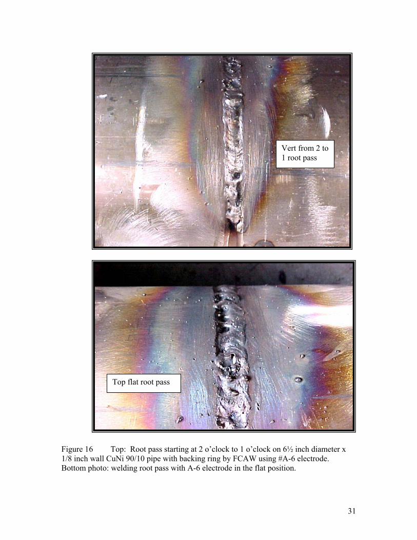
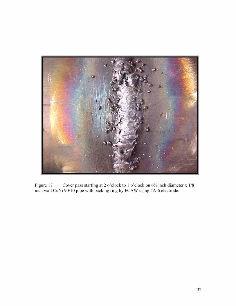
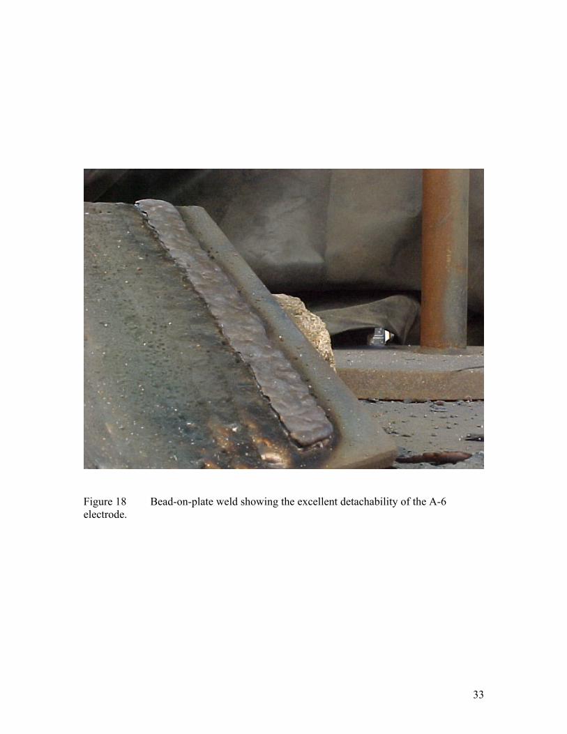
Experimental A-6 was the best electrode in this study. In Figure 16 (top photo), the root pass started at 2 o’clock to 1 o’clock on 6½ inch diameter x 1/8 inch wall CuNi 90/10 pipe with backing ring by FCAW using #A-6 electrode. Figure 17 shows the cover pass for this out-of-position butt weld. In comparison, the bottom photo in Figure 16 shows the root pass deposited with A-6 electrode in the flat position. An important problem with of the electrodes from Fabricator A was the action of the slag during welding. The slag tended to flow in front of the weld puddle leaving slag inclusions in some areas. Spatter and porosity were greatly reduced with electrode A-6, but still unacceptable. The slag detachability of the A-6 electrode was excellent as shown in Figure 18. In summary, the A-6 electrode is nearly ready for shipyard applications. It is estimated that an improved A-6 electrode can be developed within about one year (after the termination of this feasibility project). Operability of Electrode #B-3:
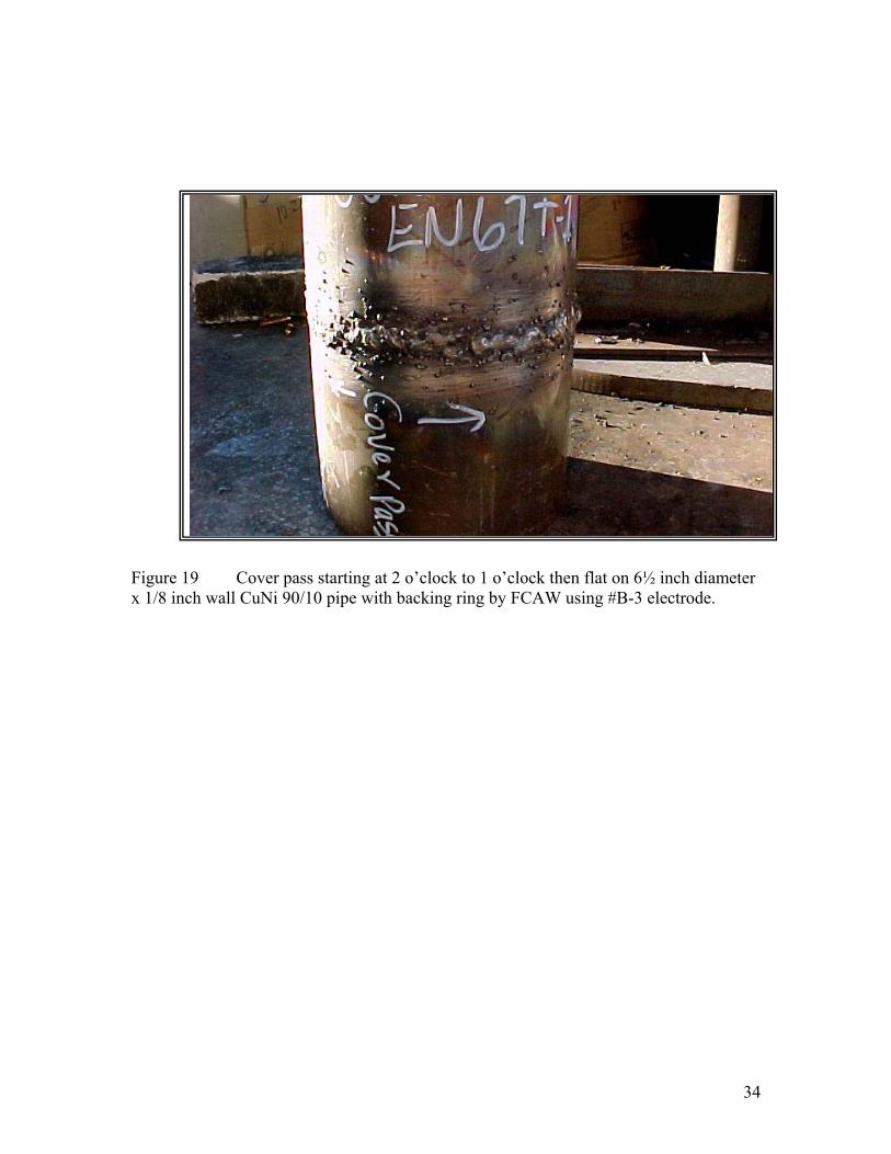
As shown in Figure 19, the operability of B-3 was not controllable. This electrode could not be evaluated further.
29
Figure 14 First test weld for operability performed at NASSCO using EN67T-1 flux cored electrode #A-3 from Fabricator “A”. Weld metal was deposited on 6½ inch diameter x 1/8 inch wall CuNi 90/10 pipe with backing ring by FCAW. Top photo: out-of-position welding starting overhead 6 to 4 o’clock; Bottom photo: flat position welding.
30
Figure 15 Root pass and cover pass test weld for operability performed at NASSCO using flux cored electrode #A-5 from Fabricator “A”. Weld metal was deposited on 6½ inch diameter x 1/8 inch wall CuNi 90/10 pipe with backing ring by FCAW. Top photo: out-of-position welding starting at 2 o’clock to 1 o’clock and flat; Bottom photo: close-up of root pass.
EN67-T1 A-5
31
Figure 16 Top: Root pass starting at 2 o’clock to 1 o’clock on 6½ inch diameter x 1/8 inch wall CuNi 90/10 pipe with backing ring by FCAW using #A-6 electrode. Bottom photo: welding root pass with A-6 electrode in the flat position.
Vert from 2 to 1 root pass
Top flat root pass
32
Figure 17 Cover pass starting at 2 o’clock to 1 o’clock on 6½ inch diameter x 1/8 inch wall CuNi 90/10 pipe with backing ring by FCAW using #A-6 electrode.
33
Figure 18 Bead-on-plate weld showing the excellent detachability of the A-6 electrode.
34
Figure 19 Cover pass starting at 2 o’clock to 1 o’clock then flat on 6½ inch diameter x 1/8 inch wall CuNi 90/10 pipe with backing ring by FCAW using #B-3 electrode.
35
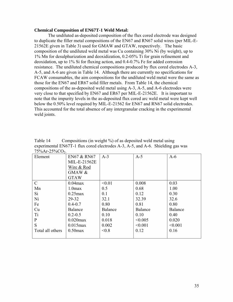
Chemical Composition of EN67T-1 Weld Metal: The undiluted as-deposited composition of the flux cored electrode was designed
to duplicate the filler metal compositions of the EN67 and RN67 solid wires (per MIL-E-21562E given in Table 3) used for GMAW and GTAW, respectively. The basic composition of the undiluted weld metal was Cu containing 30% Ni (by weight), up to 1% Mn for desulphurization and deoxidization, 0.2-05% Ti for grain refinement and deoxidation, up to 1% Si for fluxing action, and 0.4-0.7% Fe for added corrosion resistance. The undiluted chemical compositions produced by flux cored electrodes A-3, A-5, and A-6 are given in Table 14. Although there are currently no specifications for FCAW consumables, the aim compositions for the undiluted weld metal were the same as those for the EN67 and ER67 solid filler metals. From Table 14, the chemical compositions of the as-deposited weld metal using A-3, A-5, and A-6 electrodes were very close to that specified by EN67 and ER67 per MIL-E-21562E. It is important to note that the impurity levels in the as-deposited flux cored arc weld metal were kept well below the 0.50% level required by MIL-E-21562 for EN67 and RN67 solid electrodes. This accounted for the total absence of any intergranular cracking in the experimental weld joints. Table 14 Compositions (in weight %) of as deposited weld metal using experimental EN67T-1 flux cored electrodes A-3, A-5, and A-6. Shielding gas was 75%Ar-25%CO2. Element
EN67 & RN67 MIL-E-21562E Wire & Rod GMAW & GTAW
A-3 A-5 A-6
C Mn Si Ni Fe Cu Ti P S Total all others
0.04max 1.0max 0.25max 29-32 0.4-0.7 Balance 0.2-0.5 0.020max 0.015max 0.50max
<0.01 0.5 0.1 32.1 0.80 Balance 0.10 0.018 0.002 <0.8
0.008 0.68 0.12 32.39 0.81 Balance 0.10 <0.005 <0.001 0.12
0.03 1.00 0.30 32.6 0.80 Balance 0.40 0.020 <0.001 0.16
36
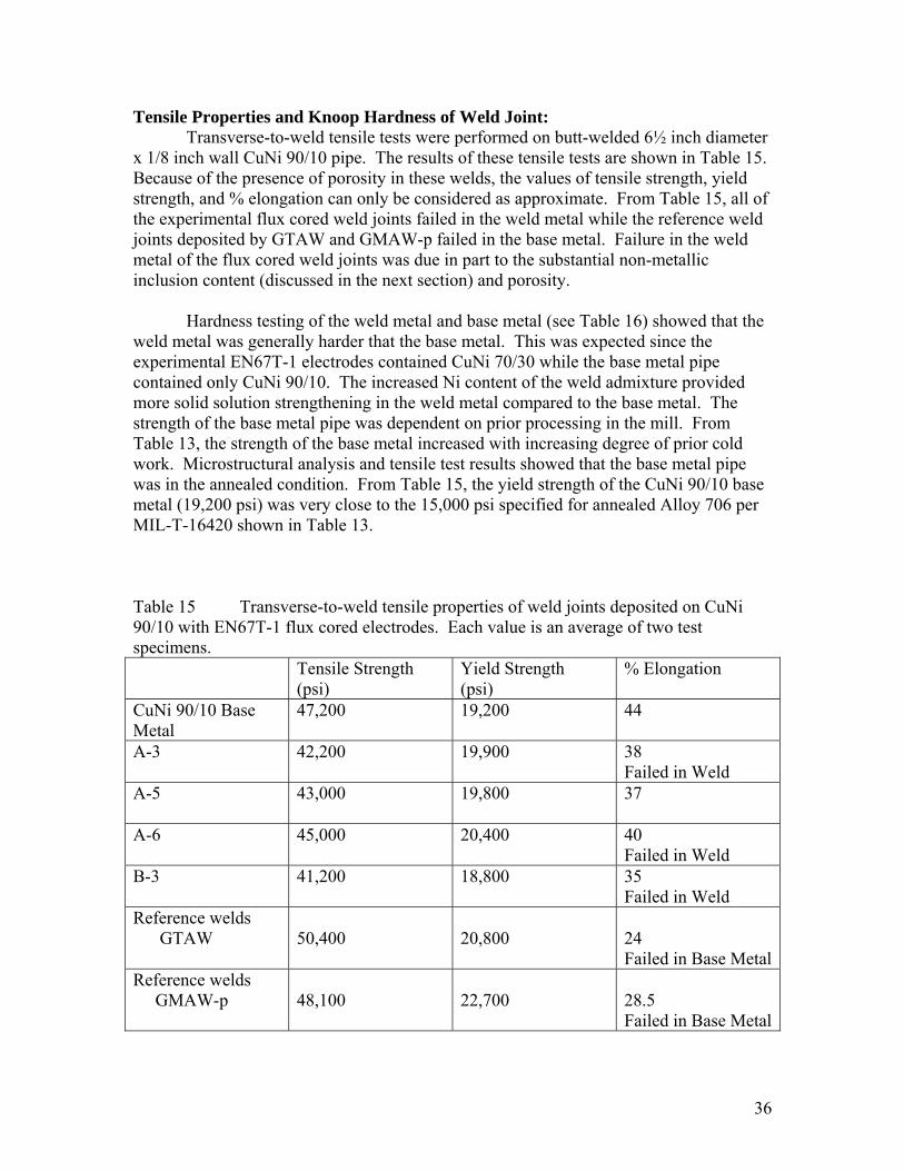
Tensile Properties and Knoop Hardness of Weld Joint: Transverse-to-weld tensile tests were performed on butt-welded 6½ inch diameter
x 1/8 inch wall CuNi 90/10 pipe. The results of these tensile tests are shown in Table 15. Because of the presence of porosity in these welds, the values of tensile strength, yield strength, and % elongation can only be considered as approximate. From Table 15, all of the experimental flux cored weld joints failed in the weld metal while the reference weld joints deposited by GTAW and GMAW-p failed in the base metal. Failure in the weld metal of the flux cored weld joints was due in part to the substantial non-metallic inclusion content (discussed in the next section) and porosity.
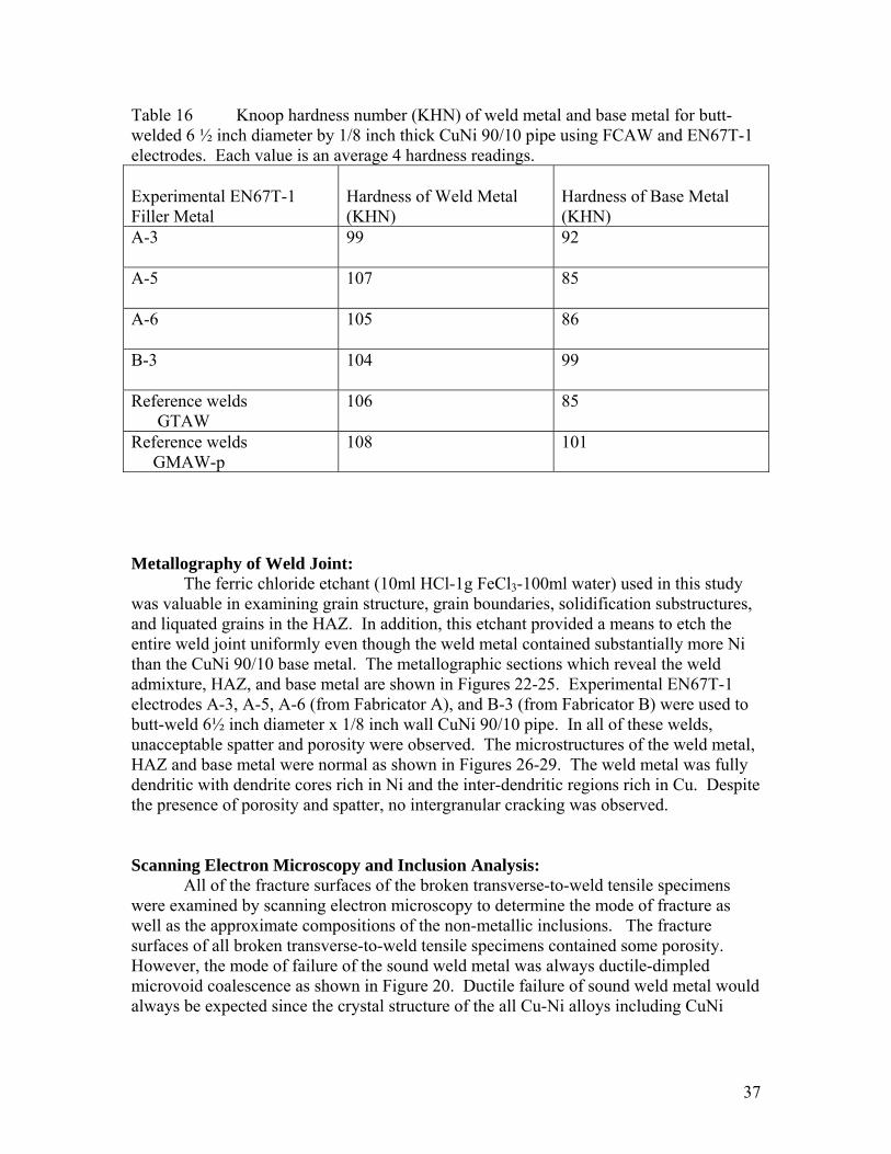
Hardness testing of the weld metal and base metal (see Table 16) showed that the
weld metal was generally harder that the base metal. This was expected since the experimental EN67T-1 electrodes contained CuNi 70/30 while the base metal pipe contained only CuNi 90/10. The increased Ni content of the weld admixture provided more solid solution strengthening in the weld metal compared to the base metal. The strength of the base metal pipe was dependent on prior processing in the mill. From Table 13, the strength of the base metal increased with increasing degree of prior cold work. Microstructural analysis and tensile test results showed that the base metal pipe was in the annealed condition. From Table 15, the yield strength of the CuNi 90/10 base metal (19,200 psi) was very close to the 15,000 psi specified for annealed Alloy 706 per MIL-T-16420 shown in Table 13. Table 15 Transverse-to-weld tensile properties of weld joints deposited on CuNi 90/10 with EN67T-1 flux cored electrodes. Each value is an average of two test specimens. Tensile Strength
(psi) Yield Strength (psi)
% Elongation
CuNi 90/10 Base Metal
47,200 19,200 44
A-3 42,200 19,900 38 Failed in Weld
A-5
43,000 19,800 37
A-6
45,000 20,400 40 Failed in Weld
B-3
41,200 18,800 35 Failed in Weld
Reference welds GTAW
50,400
20,800
24 Failed in Base Metal
Reference welds GMAW-p
48,100
22,700
28.5 Failed in Base Metal
37
Table 16 Knoop hardness number (KHN) of weld metal and base metal for butt-welded 6 ½ inch diameter by 1/8 inch thick CuNi 90/10 pipe using FCAW and EN67T-1 electrodes. Each value is an average 4 hardness readings. Experimental EN67T-1 Filler Metal
Hardness of Weld Metal (KHN)
Hardness of Base Metal (KHN)
A-3 99
92
A-5 107
85
A-6 105
86
B-3 104
99
Reference welds GTAW
106 85
Reference welds GMAW-p
108 101
Metallography of Weld Joint:
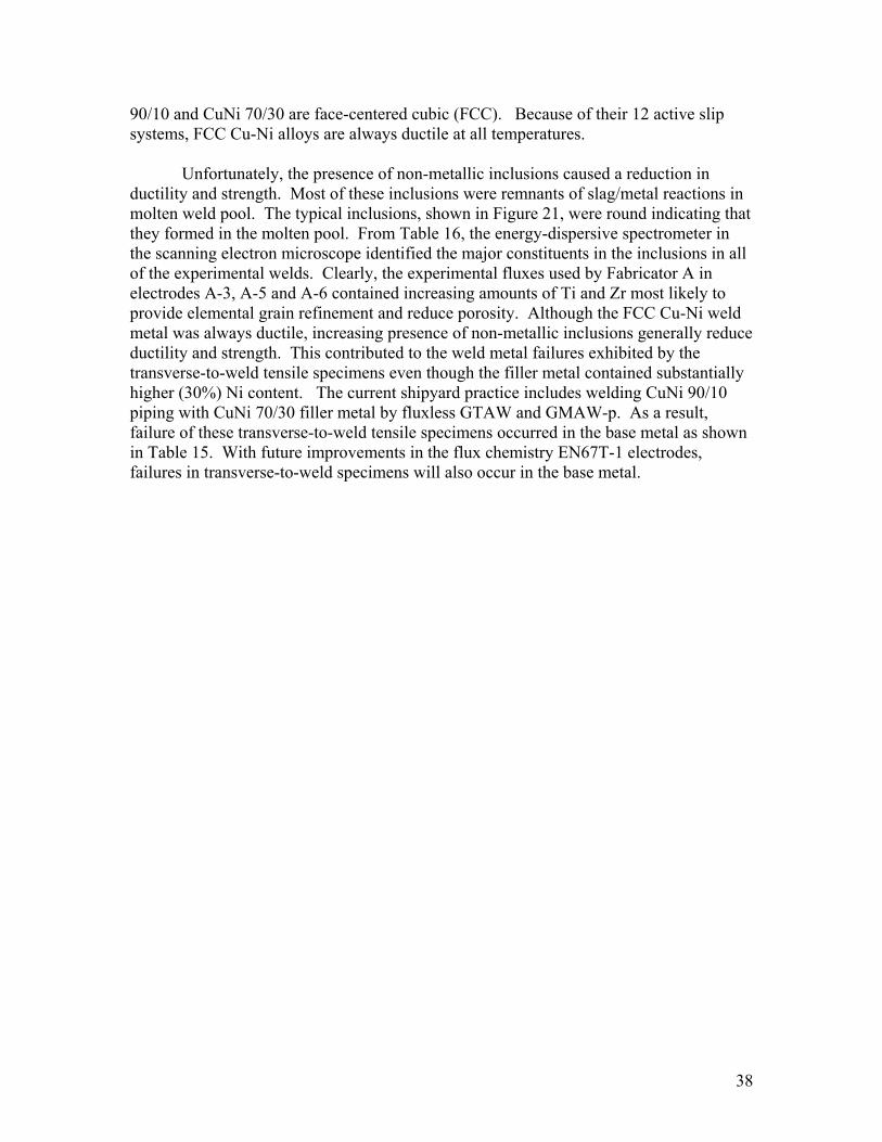
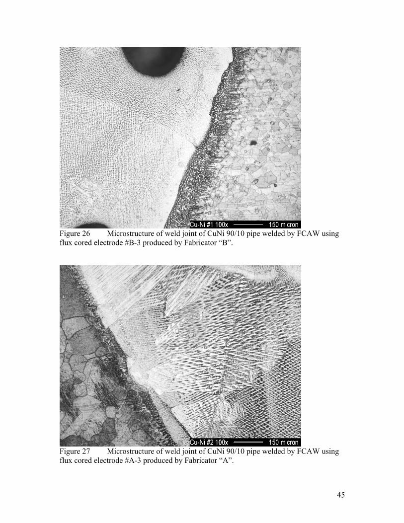
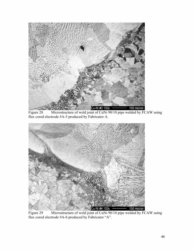
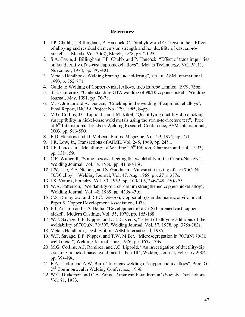
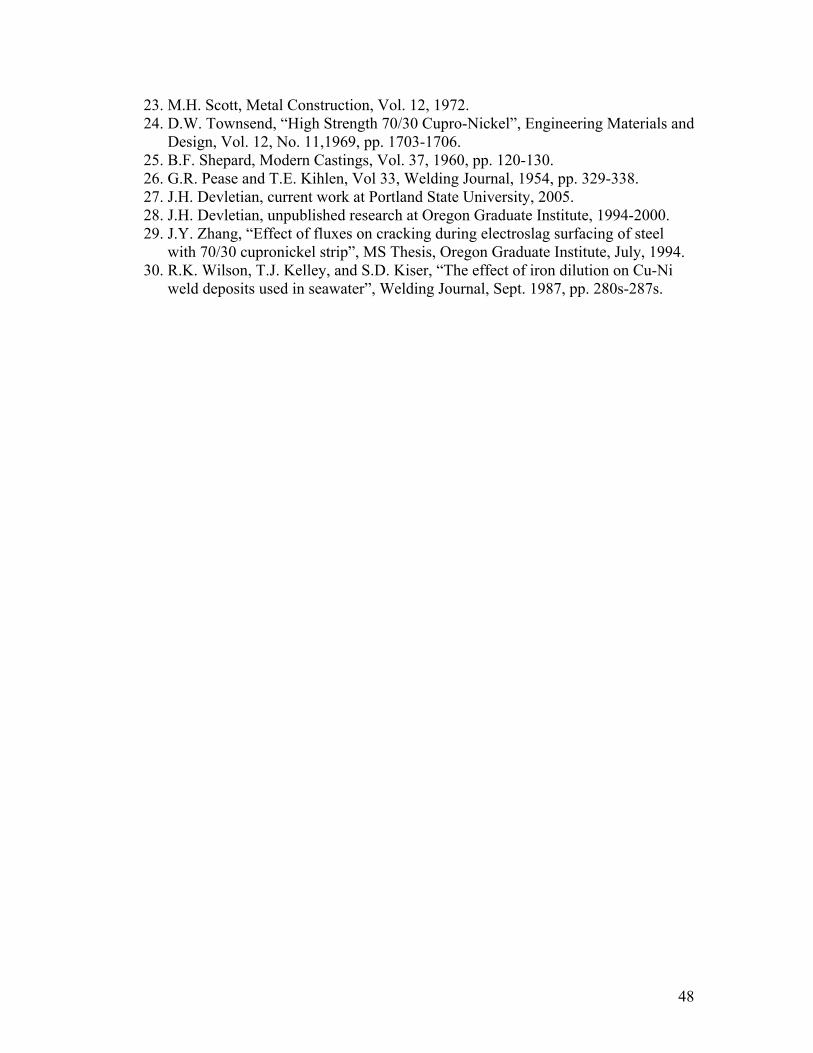
The ferric chloride etchant (10ml HCl-1g FeCl3-100ml water) used in this study was valuable in examining grain structure, grain boundaries, solidification substructures, and liquated grains in the HAZ. In addition, this etchant provided a means to etch the entire weld joint uniformly even though the weld metal contained substantially more Ni than the CuNi 90/10 base metal. The metallographic sections which reveal the weld admixture, HAZ, and base metal are shown in Figures 22-25. Experimental EN67T-1 electrodes A-3, A-5, A-6 (from Fabricator A), and B-3 (from Fabricator B) were used to butt-weld 6½ inch diameter x 1/8 inch wall CuNi 90/10 pipe. In all of these welds, unacceptable spatter and porosity were observed. The microstructures of the weld metal, HAZ and base metal were normal as shown in Figures 26-29. The weld metal was fully dendritic with dendrite cores rich in Ni and the inter-dendritic regions rich in Cu. Despite the presence of porosity and spatter, no intergranular cracking was observed. Scanning Electron Microscopy and Inclusion Analysis:
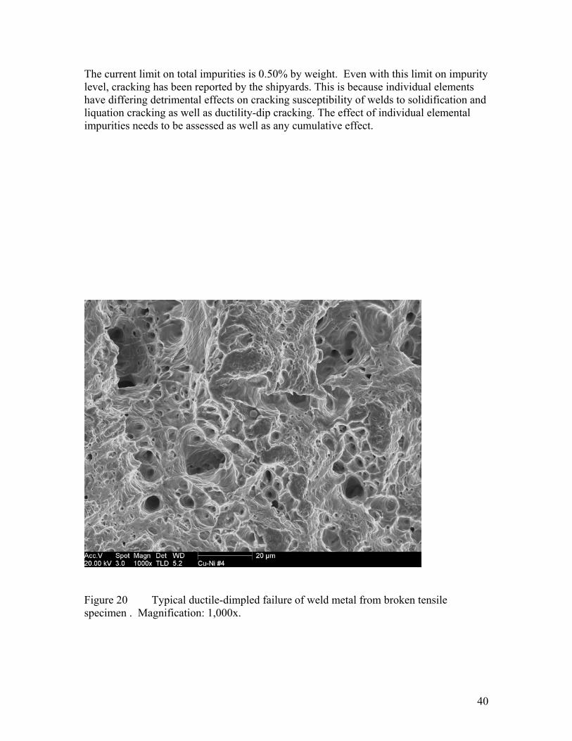
All of the fracture surfaces of the broken transverse-to-weld tensile specimens were examined by scanning electron microscopy to determine the mode of fracture as well as the approximate compositions of the non-metallic inclusions. The fracture surfaces of all broken transverse-to-weld tensile specimens contained some porosity. However, the mode of failure of the sound weld metal was always ductile-dimpled microvoid coalescence as shown in Figure 20. Ductile failure of sound weld metal would always be expected since the crystal structure of the all Cu-Ni alloys including CuNi
38
90/10 and CuNi 70/30 are face-centered cubic (FCC). Because of their 12 active slip systems, FCC Cu-Ni alloys are always ductile at all temperatures.
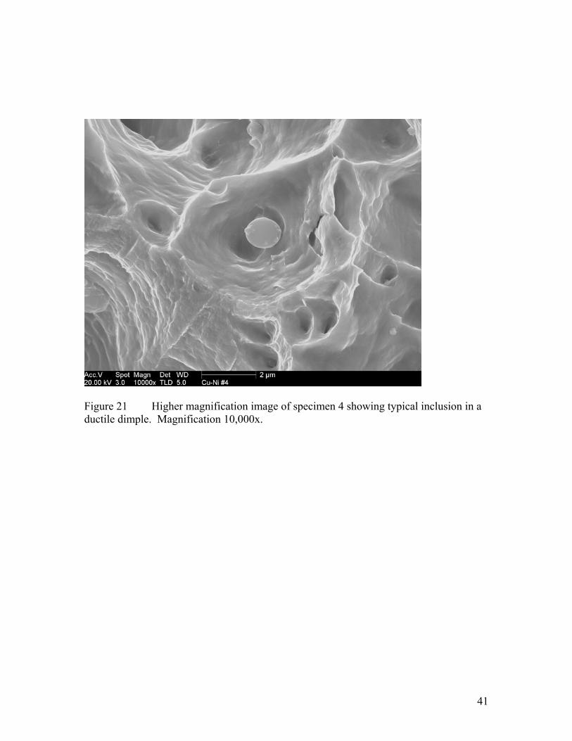
Unfortunately, the presence of non-metallic inclusions caused a reduction in
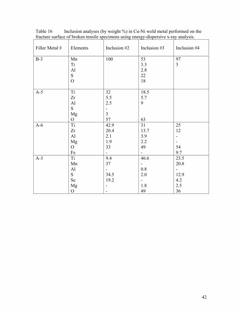
ductility and strength. Most of these inclusions were remnants of slag/metal reactions in molten weld pool. The typical inclusions, shown in Figure 21, were round indicating that they formed in the molten pool. From Table 16, the energy-dispersive spectrometer in the scanning electron microscope identified the major constituents in the inclusions in all of the experimental welds. Clearly, the experimental fluxes used by Fabricator A in electrodes A-3, A-5 and A-6 contained increasing amounts of Ti and Zr most likely to provide elemental grain refinement and reduce porosity. Although the FCC Cu-Ni weld metal was always ductile, increasing presence of non-metallic inclusions generally reduce ductility and strength. This contributed to the weld metal failures exhibited by the transverse-to-weld tensile specimens even though the filler metal contained substantially higher (30%) Ni content. The current shipyard practice includes welding CuNi 90/10 piping with CuNi 70/30 filler metal by fluxless GTAW and GMAW-p. As a result, failure of these transverse-to-weld tensile specimens occurred in the base metal as shown in Table 15. With future improvements in the flux chemistry EN67T-1 electrodes, failures in transverse-to-weld specimens will also occur in the base metal.
39
CONCLUSIONS
This one-year investigation has proven that it is feasible to develop an all-position CuNi 70/30 flux cored electrode (identified as EN67T-1) for flux-cored arc welding (FCAW) of CuNi 90/10 piping.
Specific conclusions concerning the operability of the EN67T-1 experimental electrodes for welding CuNi 90/10 pipe as well as the resulting metallurgical evaluation and mechanical properties are as follows:
• The flux cored electrode exhibiting the best operability is #A-6 developed by Fabricator “A”. The operability of this experimental EN67T-1 flux cored electrode is promising in the flat position. Out-of-position FCAW requires some additional work.
• Porosity and spatter need to be reduced to acceptable levels. • No cracking was observed in either the weld metal or HAZ of the experimental
flux cored welds. Weld and HAZ microstructures appear normal and consist of a single phase solid solution of Cu, Ni, and other minor alloy additions.
• Transverse-to-weld tensile specimens generally fail in the weld metal due to the presence of non-metallic inclusions and porosity. The mode of fracture of the broken tensile specimens is always ductile-dimpled microvoid coalescence. Similar transverse-to-weld tensile specimens containing welds deposited by conventional GTAW and GMAW-p fail in the base metal due to the freedom from inclusions and porosity in the weld metal.
• Since feasibility has been established, it is estimated that a suitable EN67T-1 flux cored electrode can be developed for use in Naval ships within about a year.
NEED FOR FUTURE RESEARCH
Experimental welds deposited by FCAW on 6 ½ inch diameter by 1/8 inch wall have been crack-free. The impurity levels of undiluted weld metal deposited with A-3, A-5, and A-6 flux cored electrodes were well below the 0.50% maximum specified for EN67 and ER67. The microstructures of the flux-cored arc welds deposited with EN67T-1 electrodes were as good as those deposited with GTAW and GMAW-p. Out-of-position operability still needs additional work. Porosity and spatter need to be reduced to acceptable levels.
The Vice President of Technology for Fabricator “A” (one of this project’s research team partners) will actively continue development of the EN67T-1 flux cored electrode after the NSRP contract period has ended (on January 30, 2006). Fabricator “A” will use its own internal research funds to continue this work. Mike Sullivan of NASSCO will also continue to test any of the promising flux cored electrodes made by Fabricator “A”.
In addition, research is needed to determine the practical limits, such as P, S, Pb, Te, Bi, and Se on weld metal cracking in typical CuNi 90/10 pipe welding applications.
40
The current limit on total impurities is 0.50% by weight. Even with this limit on impurity level, cracking has been reported by the shipyards. This is because individual elements have differing detrimental effects on cracking susceptibility of welds to solidification and liquation cracking as well as ductility-dip cracking. The effect of individual elemental impurities needs to be assessed as well as any cumulative effect.
Figure 20 Typical ductile-dimpled failure of weld metal from broken tensile specimen . Magnification: 1,000x.
41
Figure 21 Higher magnification image of specimen 4 showing typical inclusion in a ductile dimple. Magnification 10,000x.
42
Table 16 Inclusion analyses (by weight %) in Cu-Ni weld metal performed on the fracture surface of broken tensile specimens using energy-dispersive x-ray analysis. Filler Metal #
Elements
Inclusion #2
Inclusion #3
Inclusion #4
B-3 Mn Ti Al S O
100 53 3.3 2.8 22 18
97 3
A-5 Ti Zr Al S Mg O
32 5.5 2.5 - 3 57
18.5 5.7 9 63
A-6 Ti Zr Al Mg O Fe
42.9 20.4 2.1 1.9 33 -
31 13.7 3.9 2.2 49 -
25 12 - - 54 9.7
A-3 Ti Mn Al S Se Mg O
9.4 37 - 34.5 19.2 - -
46.6 - 0.8 2.0 - 1.8 49
23.5 20.8 - 12.9 4.2 2.5 36
43
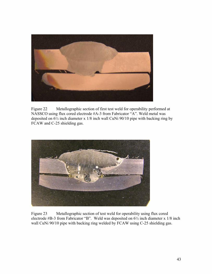
Figure 22 Metallographic section of first test weld for operability performed at NASSCO using flux cored electrode #A-3 from Fabricator “A”. Weld metal was deposited on 6½ inch diameter x 1/8 inch wall CuNi 90/10 pipe with backing ring by FCAW and C-25 shielding gas.
Figure 23 Metallographic section of test weld for operability using flux cored electrode #B-3 from Fabricator “B”. Weld was deposited on 6½ inch diameter x 1/8 inch wall CuNi 90/10 pipe with backing ring welded by FCAW using C-25 shielding gas.
44
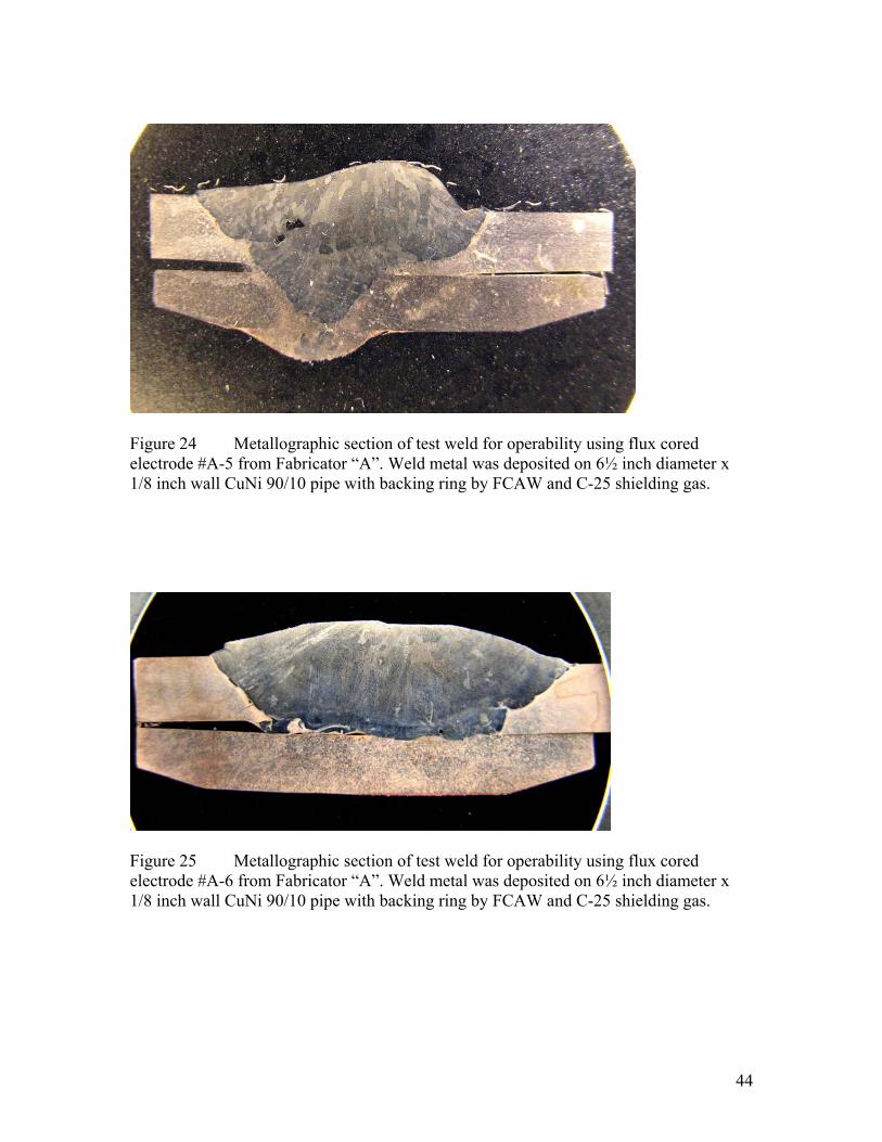
Figure 24 Metallographic section of test weld for operability using flux cored electrode #A-5 from Fabricator “A”. Weld metal was deposited on 6½ inch diameter x 1/8 inch wall CuNi 90/10 pipe with backing ring by FCAW and C-25 shielding gas.
Figure 25 Metallographic section of test weld for operability using flux cored electrode #A-6 from Fabricator “A”. Weld metal was deposited on 6½ inch diameter x 1/8 inch wall CuNi 90/10 pipe with backing ring by FCAW and C-25 shielding gas.
45
Figure 26 Microstructure of weld joint of CuNi 90/10 pipe welded by FCAW using flux cored electrode #B-3 produced by Fabricator “B”.
Figure 27 Microstructure of weld joint of CuNi 90/10 pipe welded by FCAW using flux cored electrode #A-3 produced by Fabricator “A”.
46
Figure 28 Microstructure of weld joint of CuNi 90/10 pipe welded by FCAW using flux cored electrode #A-5 produced by Fabricator A.
Figure 29 Microstructure of weld joint of CuNi 90/10 pipe welded by FCAW using flux cored electrode #A-6 produced by Fabricator “A”.
47
References:
1. J.P. Chubb, J. Billingham, P. Hancock, C. Dimbylow and G. Newcombe, “Effect of alloying and residual elements on strength and hot ductility of cast cupro-nickel”, J. Metals, Vol. 30(3), March, 1978, pp. 20-25.
2. S.A. Gavin, J. Billingham, J.P. Chubb, and P. Hancock, “Effect of trace impurities on hot ductility of as-cast cupronickel alloys”, Metals Technology, Vol. 5(11), November, 1978, pp. 397-401.
3. Metals Handbook, Welding brazing and soldering”, Vol. 6, ASM International, 1993, p. 752-771.
4. Guide to Welding of Copper-Nickel Alloys, Inco Europe Limited, 1979, 75pp. 5. S.H. Gutierrez, “Understanding GTA welding of 90/10 copper-nickel”, Welding
Journal, May, 1991, pp. 76-78. 6. M. F. Jordan and A. Duncan, “Cracking in the welding of cupronickel alloys”,
Final Report, INCRA Project No. 329, 1985, 84pp. 7. M.G. Collins, J.C. Lippold, and J.M. Kikel, “Quantifying ductility-dip cracking
susceptibility in nickel-base weld metals using the strain-to-fracture test”, Proc. of 6th International Trends in Welding Research Conference, ASM International, 2003, pp. 586-590.
8. E.D. Hondros and D. McLean, Philos. Magazine, Vol. 29, 1974, pp. 771 9. J.R. Low, Jr., Transactions of AIME, Vol. 245, 1969, pp. 2481. 10. J.F. Lancaster, “Metallurgy of Welding”, 5th Edition, Chapman and Hall, 1993,
pp. 158-159. 11. C.E. Witherall, “Some factors affecting the weldability of the Cupro-Nickels”,
Welding Journal, Vol. 39, 1960, pp. 411s-416s. 12. J.W. Lee, E.E. Nichols, and S. Goodman, “Varestraint testing of cast 70CuNi
70/30 alloy”, Welding Journal, Vol. 47, Aug. 1968, pp. 371s-377s. 13. J.S. Vanick, Foundry, Vol. 80, 1952, pp. 100-105, 246-248, 250-253. 14. W.A. Patterson, “Weldability of a chromium strengthened copper-nickel alloy”,
Welding Journal, Vol. 48, 1969, pp. 425s-430s. 15. C.S. Dimbylow, and R.J.C. Dawson, Copper alloys in the marine environment,
Paper 5, Copper Development Association, 1978. 16. F.J. Ansuini and F.A. Badia, “Development of a Cr-Si hardened cast copper-
nickel”, Modern Castings, Vol. 55, 1970, pp. 165-168. 17. W.F. Savage, E.F. Nippes, and J.E. Casteras, “Effect of alloying additions of the
weldability of 70CuNi 70/30”, Welding Journal, Vol. 57, 1978, pp. 375s-382s. 18. Metals Handbook, Desk Edition, ASM International, 1985. 19. W.F. Savage, E.F. Nippes, and T.W. Miller, “Microsegregation in 70CuNi 70/30
weld metal”, Welding Journal, June, 1976, pp. 165s-173s. 20. M.G. Collins, A.J. Ramirez, and J.C. Lippold, “An investigation of ductility-dip
cracking in nickel-based weld metal – Part III”, Welding Journal, February 2004, pp. 39s-49s.
21. E.A. Taylor and A.W. Burn, “Inert gas welding of copper and its alloys”, Proc. Of 2nd Commonwealth Welding Conference, 1966.
22. W.C. Dickerson and C.A. Zanis, American Foundryman’s Society Transactions, Vol. 81, 1973.
48
23. M.H. Scott, Metal Construction, Vol. 12, 1972. 24. D.W. Townsend, “High Strength 70/30 Cupro-Nickel”, Engineering Materials and
Design, Vol. 12, No. 11,1969, pp. 1703-1706. 25. B.F. Shepard, Modern Castings, Vol. 37, 1960, pp. 120-130. 26. G.R. Pease and T.E. Kihlen, Vol 33, Welding Journal, 1954, pp. 329-338. 27. J.H. Devletian, current work at Portland State University, 2005. 28. J.H. Devletian, unpublished research at Oregon Graduate Institute, 1994-2000. 29. J.Y. Zhang, “Effect of fluxes on cracking during electroslag surfacing of steel
with 70/30 cupronickel strip”, MS Thesis, Oregon Graduate Institute, July, 1994. 30. R.K. Wilson, T.J. Kelley, and S.D. Kiser, “The effect of iron dilution on Cu-Ni
weld deposits used in seawater”, Welding Journal, Sept. 1987, pp. 280s-287s.