fluorescentna mikroskopija. tehnike oslikavanja ... · dual nature of light and limitations ... ...
TRANSCRIPT

6/21/2017
1
Fluorescentna mikroskopija. Tehnike oslikavanja, poboljšanje rezolucije
zaobilaženjem difrakcione barijere i izučavanjedinamičkih procesa
Dr Vladana Vukojević, Associate Professor
Karolinska Institutet, Department of Clinical Neuroscience (CNS)Center for Molecular Medicine (CMM), Stockholm, Sweden
Fakultet za fizičku hemiju, Univerzitet u Beogradu27. juni, Beograd, Srbija
Karolinska Institutet, a medical universitywith a mission to contribute to the improvement of human
health through research, education and information
Research goalsThe goal for our research is to achieve scientific breakthroughsthat change the view of human health and disease, as well asnormal vital processes. Research results should lead toinnovations and practical applications that can be implementedwithin the health service sector.
Educational goalsThe goal for our educational programs is to strengthen their linkto research, and to prepare the students for engagement inresearch. They should provide the best possible conditions towork in, lead and continue to develop activities in collaborationwith other professions.
http://search.ki.se/search.do;jsessionid=1C744137F1321DCBDC6866C5BF4207C7?q=facts+about+karolinska+ppt&site=internwebben

6/21/2017
2
Outline• Brief recapitulation of basic concepts: light-matter interaction
• What is light?
• What is fluorescence?
• What are the most important properties of fluorophores and why is this important for you to know them?
• What is fluorescence quenching and how to avoid it?
• Fluorescence Imaging - Confocal Laser Scanning Microscope (CLSM)
• The confocal principle
• Upright vs. inverted microscopes
• Epifluorescence microscopes
• The light path in epifluorescence microscopes
• Magnification vs. resolution
• Limits of resolution in epifluorescence microscopy
• Evading the resolution limit imposed by the diffraction of light
• Super-resolution fluorescence microscopy imaging techniques
Imaging techniques in biomedical research
(Image modified from http://www.hinz.org.nz/uploads/journal/fig1_041205.jpg)
fFMIDSLMFCSFCCSFIONAFLIMFLIPFRAPFRETLSFMmSPIMPALM2PEMRICSSIMSPIMSHREKSTEDSTORMTIRFTREXM
Spatial resolution of imaging techniquesAtom Protein Cell Tissue Organ Organism
10-12 m 10-9 m 10-6 m 10-3 m 10-1 m > 10-0 m
Temporal resolution of imaging techniquesMolecular events Diffusion Cell motility Mitosis Protein HumanChannel gating Cell signaling Cell turnover lifetime
<10-6 s 10-3 s 100 s 103 s 104 s > 109 s
Sensitivity of imaging techniquesSingle-molecule nM-µM µM-mM <mM
6/21/2017
3
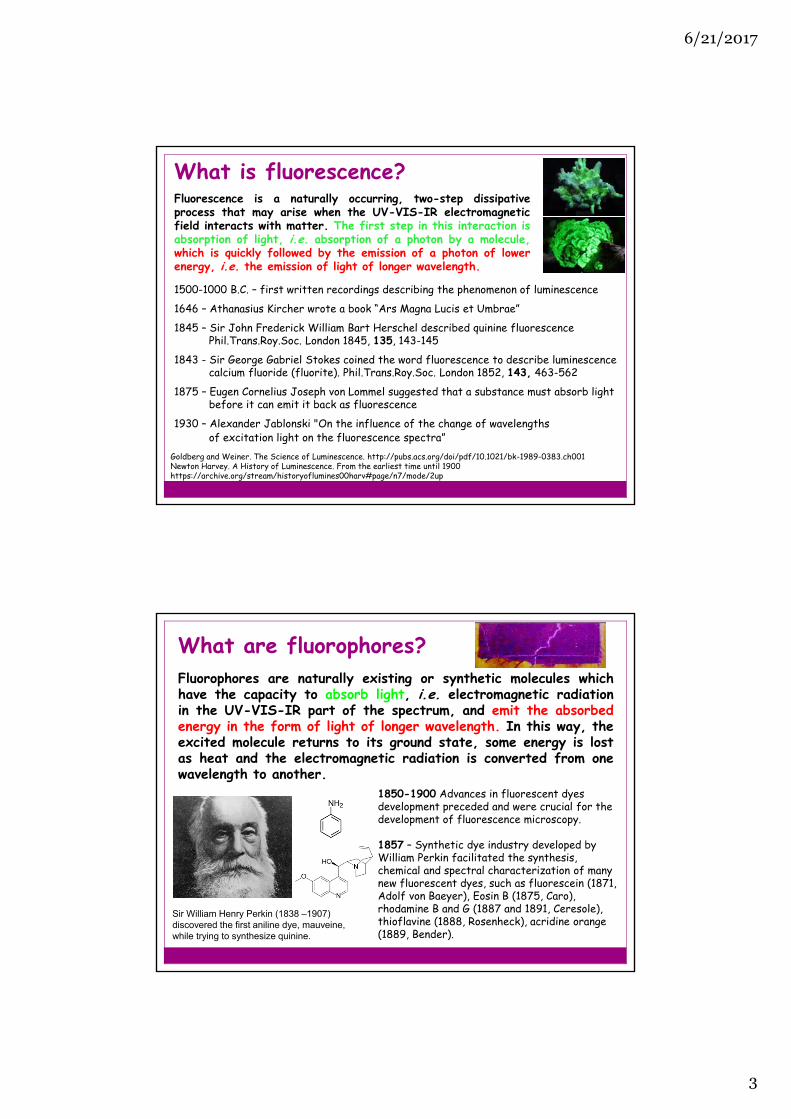
What is fluorescence?Fluorescence is a naturally occurring, two-step dissipativeprocess that may arise when the UV-VIS-IR electromagneticfield interacts with matter. The first step in this interaction isabsorption of light, i.e. absorption of a photon by a molecule,which is quickly followed by the emission of a photon of lowerenergy, i.e. the emission of light of longer wavelength.
1500-1000 B.C. – first written recordings describing the phenomenon of luminescence
1646 – Athanasius Kircher wrote a book “Ars Magna Lucis et Umbrae”
1845 – Sir John Frederick William Bart Herschel described quinine fluorescence Phil.Trans.Roy.Soc. London 1845, 135, 143-145
1843 - Sir George Gabriel Stokes coined the word fluorescence to describe luminescencecalcium fluoride (fluorite). Phil.Trans.Roy.Soc. London 1852, 143, 463-562
1875 – Eugen Cornelius Joseph von Lommel suggested that a substance must absorb lightbefore it can emit it back as fluorescence
1930 – Alexander Jablonski "On the influence of the change of wavelengthsof excitation light on the fluorescence spectra”
Goldberg and Weiner. The Science of Luminescence. http://pubs.acs.org/doi/pdf/10.1021/bk-1989-0383.ch001Newton Harvey. A History of Luminescence. From the earliest time until 1900 https://archive.org/stream/historyoflumines00harv#page/n7/mode/2up
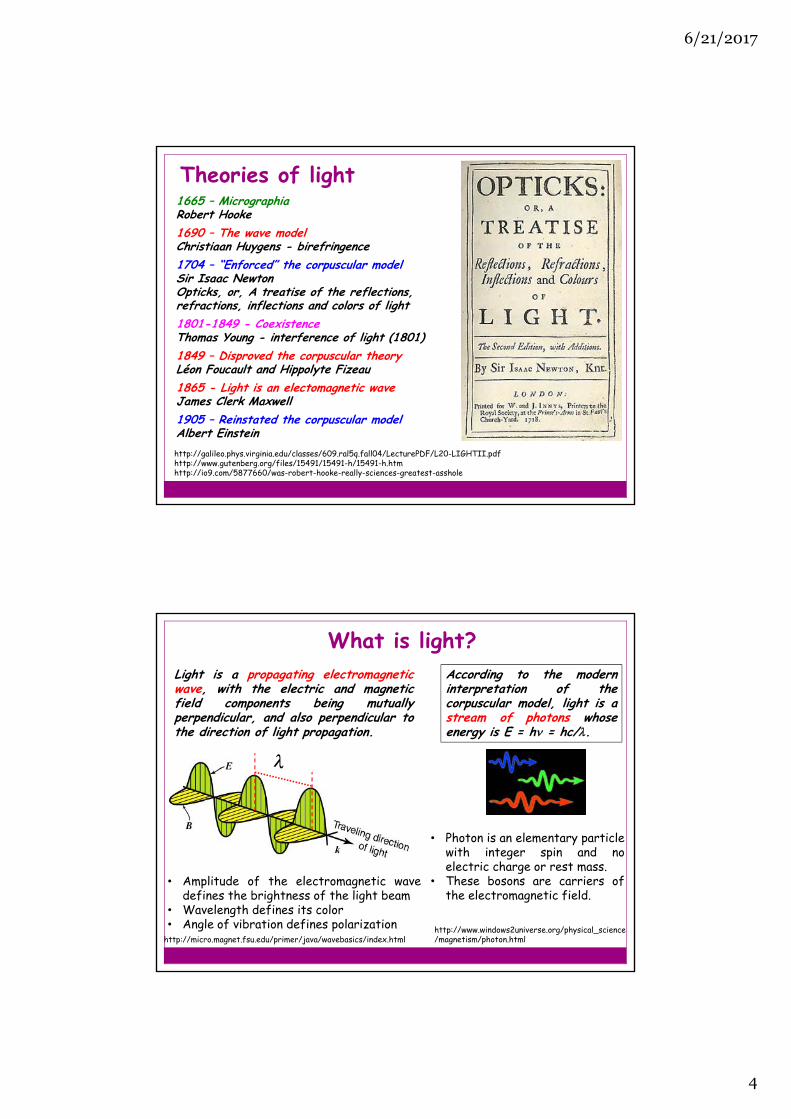
What are fluorophores?Fluorophores are naturally existing or synthetic molecules whichhave the capacity to absorb light, i.e. electromagnetic radiationin the UV-VIS-IR part of the spectrum, and emit the absorbedenergy in the form of light of longer wavelength. In this way, theexcited molecule returns to its ground state, some energy is lostas heat and the electromagnetic radiation is converted from onewavelength to another.
1850-1900 Advances in fluorescent dyes development preceded and were crucial for the development of fluorescence microscopy.
1857 – Synthetic dye industry developed by William Perkin facilitated the synthesis, chemical and spectral characterization of many new fluorescent dyes, such as fluorescein (1871, Adolf von Baeyer), Eosin B (1875, Caro), rhodamine B and G (1887 and 1891, Ceresole), thioflavine (1888, Rosenheck), acridine orange (1889, Bender).
Sir William Henry Perkin (1838 –1907) discovered the first aniline dye, mauveine, while trying to synthesize quinine.
6/21/2017
4
Theories of light1665 – MicrographiaRobert Hooke1690 – The wave model Christiaan Huygens - birefringence1704 – “Enforced” the corpuscular modelSir Isaac NewtonOpticks, or, A treatise of the reflections, refractions, inflections and colors of light1801-1849 - CoexistenceThomas Young - interference of light (1801)1849 – Disproved the corpuscular theory Léon Foucault and Hippolyte Fizeau1865 - Light is an electomagnetic waveJames Clerk Maxwell1905 – Reinstated the corpuscular modelAlbert Einsteinhttp://galileo.phys.virginia.edu/classes/609.ral5q.fall04/LecturePDF/L20-LIGHTII.pdfhttp://www.gutenberg.org/files/15491/15491-h/15491-h.htmhttp://io9.com/5877660/was-robert-hooke-really-sciences-greatest-asshole
Light is a propagating electromagneticwave, with the electric and magneticfield components being mutuallyperpendicular, and also perpendicular tothe direction of light propagation.
http://micro.magnet.fsu.edu/primer/java/wavebasics/index.html
• Amplitude of the electromagnetic wavedefines the brightness of the light beam
• Wavelength defines its color• Angle of vibration defines polarization
What is light? According to the moderninterpretation of thecorpuscular model, light is astream of photons whoseenergy is E = h = hc/.
• Photon is an elementary particlewith integer spin and noelectric charge or rest mass.
• These bosons are carriers ofthe electromagnetic field.
http://www.windows2universe.org/physical_science/magnetism/photon.html
6/21/2017
5
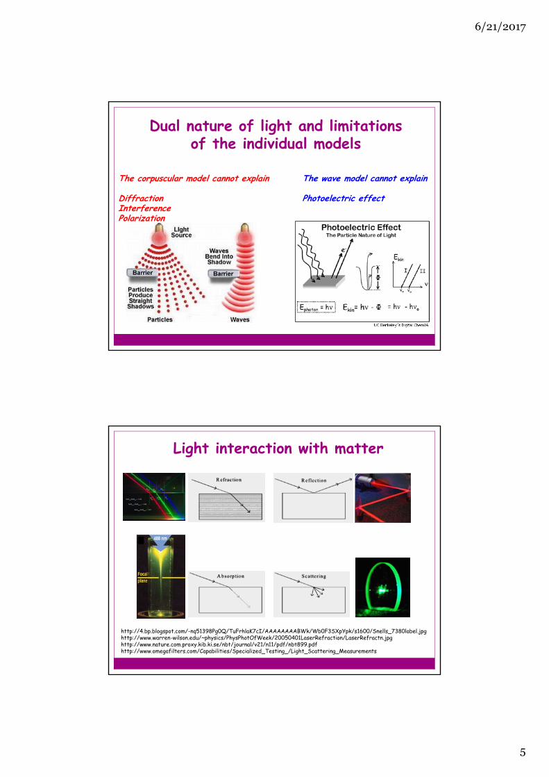
Dual nature of light and limitations of the individual models
The corpuscular model cannot explain The wave model cannot explain
Diffraction Photoelectric effectInterference Polarization
Light interaction with matter
http://4.bp.blogspot.com/-nq51398Pg0Q/TuFrhlaK7cI/AAAAAAAABWk/Wb0F3SXpYpk/s1600/Snells_7380label.jpghttp://www.warren-wilson.edu/~physics/PhysPhotOfWeek/20050401LaserRefraction/LaserRefractn.jpghttp://www.nature.com.proxy.kib.ki.se/nbt/journal/v21/n11/pdf/nbt899.pdfhttp://www.omegafilters.com/Capabilities/Specialized_Testing_/Light_Scattering_Measurements
6/21/2017
6
c,ε’
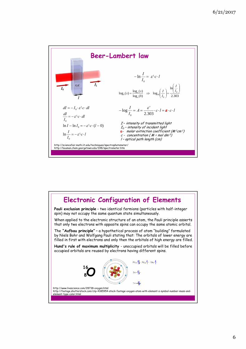
Beer-Lambert law
I – intensity of transmitted lightI0 – intensity of incident light- molar extinction coefficient (M-1cm-1) c - concentration ( M = mol dm-3)l – optical path length (cm)
303.2
ln
log)(log
)(log)(log 0
010
II
I
I
b
xx
a
ab
lcI
I
lcII
dlcI
dI
dlcIdI
'ln
)0('lnln
'
'
0
0
0
0
lcI
I 'ln
0
lclcAI
I
303.2
'log
0
http://sciencefair.math.iit.edu/techniques/spectrophotometer/http://bouman.chem.georgetown.edu/S98/spectrometer.htm
ε
ε
Pauli exclusion principle - two identical fermions (particles with half-integer spin) may not occupy the same quantum state simultaneously.When applied to the electronic structure of an atom, the Pauli principle asserts that only two electrons with opposite spins can occupy the same atomic orbital. The “Aufbau principle” – a hypothetical process of atom “building” formulated by Niels Bohr and Wolfgang Pauli stating that: The orbitals of lower energy are filled in first with electrons and only then the orbitals of high energy are filled.Hund's rule of maximum multiplicity - unoccupied orbitals will be filled before occupied orbitals are reused by electrons having different spins.
Electronic Configuration of Elements
http://www.livescience.com/28738-oxygen.htmlhttp://footage.shutterstock.com/clip-4385954-stock-footage-oxygen-atom-with-element-s-symbol-number-mass-and-element-type-color.html
816O
6/21/2017
7
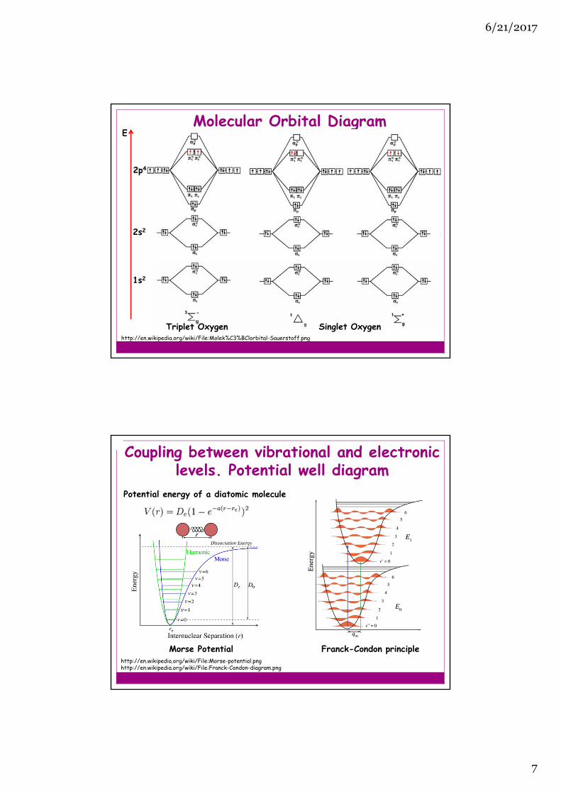
Molecular Orbital Diagram
1s2
2s2
2p4
E
Triplet Oxygen Singlet Oxygenhttp://en.wikipedia.org/wiki/File:Molek%C3%BClorbital-Sauerstoff.png
Coupling between vibrational and electronic levels. Potential well diagram
Morse Potential Franck-Condon principlehttp://en.wikipedia.org/wiki/File:Morse-potential.png http://en.wikipedia.org/wiki/File:Franck-Condon-diagram.png
Potential energy of a diatomic molecule

6/21/2017
8
http://www.olympusmicro.com/primer/java/jablonski/jabintro/index.html
• Electronic states arearranged vertically by energyand grouped horizontally byspin multiplicity.
• Radiative transitions areindicated by straight arrowsand non-radiative transitionsby wavy arrows.
• The vibrational ground statesof each electronic state areindicated with thick lines, thehigher vibrational states withthinner lines.
Jablonski diagram
Characteristics of fluorescence emissionStokes shift The mirror-image rule
Lakowicz JR. Principles of Fluorescence Spectroscopy
6/21/2017
9
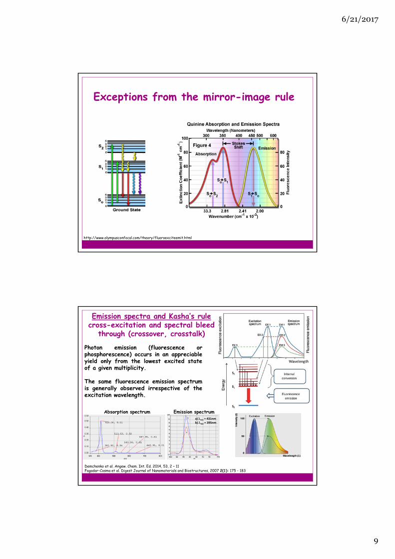
Exceptions from the mirror-image rule
http://www.olympusconfocal.com/theory/fluoroexciteemit.html
Emission spectra and Kasha’s rulecross-excitation and spectral bleed
through (crossover, crosstalk)
a) exc = 431nmb) exc = 395nm
Absorption spectrum Emission spectrum
Photon emission (fluorescence orphosphorescence) occurs in an appreciableyield only from the lowest excited stateof a given multiplicity.
The same fluorescence emission spectrumis generally observed irrespective of theexcitation wavelength.
Demchenko et al. Angew. Chem. Int. Ed. 2014, 53, 2 – 11Fagadar-Cosma et al. Digest Journal of Nanomaterials and Biostructures, 2007 2(1): 175 - 183

6/21/2017
10
Fluorescence lifetimeThe lifetime (τ) of the excited state is the average amount of time that the molecule spends in that state before returning to the ground state. and knr are rate constants for the radiative and nonradiative decay, respectively.
Typically fluorescence lifetimes are < 10 ns. Vibrational: internal relaxation occurs on much shorter timescales (10-12 s).
The fluorescence process is random. The population of the excited state is governed by Boltzmann statistics. The decay to the ground state is exponential in time – hence the lifetime is an average value: at t=τ, about 63% of the molecules have decayed and the remaining 37% will decay t>τ.
(in the absence of nonradiative processes)
Quantum yield is among the most important properties of afluorescent dye. It is defined as the number of photonsemitted relative to the number of photons absorbed.
Molecules such as rhodamine have a quantum yield near 1.
Quantum yield is determined by the rate constants for radiative and non-radiative emission:
Quantum yield
Lakowicz JR. Principles of Fluorescence Spectroscopy; http://pubs.rsc.org.proxy.kib.ki.se/en/content/articlepdf/2009/pp/b903357m
kr + kchem + kdec + kET + ket + kpt + ktict + kic + kisc
F =kr Rate constants:
kr = radiativekchem = photochemistrykdec = decompositionkET = energy transferket = electron transferktict = proton transferktict = twisted-intramolecular
charge transferkic = internal conversionkisc = intersystem crossing
kr + knr
F = kr

6/21/2017
11
Brightness
ɛ - molar extinction coefficient (M-1cm-1) F - quantum yield
1000BR =
ɛ F
eGFP:F = 0.6
ɛ = 56000 M-1cm-1
BR = 33.6 M-1cm-1
BRrelative = BRBReGFP
Relative brightness:
Brightness is equal to the product of the extinction coefficient andthe quantum yield, divided by 1000 (convention).
Molecular Brightness
Lakowicz JR. Principles of Fluorescence SpectroscopyChudakov et al. Physiological Reviews 2010 90:1103-1163. (http://physrev.physiology.org/content/physrev/90/3/1103.full.pdf)

6/21/2017
12
Examples of organic fluorophores
http://www.hhmi.org/research/tailoring-fluorescent-molecules-biological-applications
http://nic.ucsf.edu/FPvisualization/http://nic.ucsf.edu/dokuwiki/doku.php?id=fluorescent_proteinsChudakov et al. Physiological Reviews 2010 90:1103-1163. (http://physrev.physiology.org/content/physrev/90/3/1103.full.pdf)
Fluorescent protein properties

6/21/2017
13
aSource of data unless otherwise noted. bExcitation maximum in nm. cEmission maximum in nm. dExtinction coefficient in mM-1cm-1, determined by alkalidenaturation method. eFluorescence quantum yield. fProduct of ε and (x003C6), expressed as a percentage of mEGFP brightness. gTime in s tophotobleach from 1000 to 500 photons per s per molecule in live cells under widefield arc-lamp illumination. hpH at which fluorescence intensity is 50% ofits maximum value. iTime in min for fluorescence to reach its half-maximal value after exposure to oxygen at 37 °C. ND = not determined.
Shaner et al. Nat Methods. 2013 May; 10(5): 10.1038/nmeth.2413
Physical and optical data
Fluorescence quenching
Lakowicz JR. Principles of Fluorescence Spectroscopyhttps://photochemistry.wordpress.com/category/quenching/
The intensity of fluorescence can be decreased by a wide number of processes.
Collisional quenching is the most typically encountered fluorescence quenching processwhere the fluorophore in the excited state is deactivated by a collision with anothermolecule in the sample, but the molecules are not chemically altered in the process.
The decrease in intensity for collisional quenching can be described by the followingequation:
A* + Q A + Q*
K - Stern-Volmer quenching constantkq – bimolecular quenching constant0 - unquenched lifetime[Q] - quencher concentration
6/21/2017
14
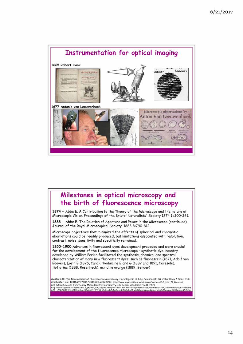
Instrumentation for optical imaging1665 Robert Hook
1677 Antonie van Leeuwenhoek
Milestones in optical microscopy andthe birth of fluorescence microscopy
1874 – Abbe E. A Contribution to the Theory of the Microscope and the nature of Microscopic Vision. Proceedings of the Bristol Naturalists' Society 1874 1:200–261.1883 – Abbe E. The Relation of Aperture and Power in the Microscope (continued). Journal of the Royal Microscopical Society. 1883 3:790–812. Microscope objectives that minimized the effects of spherical and chromatic aberrations could be readily produced, but limitations associated with resolution, contrast, noise, sensitivity and specificity remained.1850-1900 Advances in fluorescent dyes development preceded and were crucial for the development of the fluorescence microscope – synthetic dye industry developed by William Perkin facilitated the synthesis, chemical and spectral characterization of many new fluorescent dyes, such as fluorescein (1871, Adolf von Baeyer), Eosin B (1875, Caro), rhodamine B and G (1887 and 1891, Ceresole), tioflafine (1888, Rosenheck), acridine orange (1889, Bender)
Masters BR. The Development of Fluorescence Microscopy. Encyclopedia of Life Sciences (ELS). John Wiley & Sons, Ltd: Chichester. doi: 10.1002/9780470015902.a0022093; http://www.physics.bilkent.edu.tr/news/masters/ELS_Hist_Fl_Micro.pdfCell Structure and Function by Microspectrofluorometry, Elli Kohen, Academic Press, 1989http://books.google.se/books?id=iLhQAwAAQBAJ&pg=PA4&lpg=PA4&dq=Acridine+orange+Bender&source=bl&ots=Y6PJS2HyRb&sig=Wr28HhEaR86JO_c7NmWOOjlNvqI&hl=en&sa=X&ei=AENWVNS_JNGradvZgPgM&ved=0CCgQ6AEwAQ#v=onepage&q=Acridine%20orange%20Bender&f=false

6/21/2017
15
The forerunners of fluorescence microscope
August KöhlerKoehler A. New Method of Illimination for Photomicro-graphical Purposes. Journal of the Royal Microscopical Society 1894 14: 261–262.
1904 – the UV absorption microscope, Carl Zeiss, Germany
Masters BR. The Development of Fluorescence Microscopy. Encyclopedia of Life Sciences (ELS). John Wiley & Sons, Ltd: Chichester. doi: 10.1002/9780470015902.a0022093; http://www.physics.bilkent.edu.tr/news/masters/ELS_Hist_Fl_Micro.pdfCell Structure and Function by Microspectrofluorometry, Elli Kohen, Academic Press, 1989http://books.google.se/books?id=iLhQAwAAQBAJ&pg=PA4&lpg=PA4&dq=Acridine+orange+Bender&source=bl&ots=Y6PJS2HyRb&sig=Wr28HhEaR86JO_c7NmWOOjlNvqI&hl=en&sa=X&ei=AENWVNS_JNGradvZgPgM&ved=0CCgQ6AEwAQ#v=onepage&q=Acridine%20orange%20Bender&f=false
1911– Heimstädt’s fluorescence microscope, Reichert Company, Austro-Hungarian Empire
1912 – Slit ultramicroscope by Siedentopfand Zsigmondy, Zeiss, Germany
http://www.science.uva.nl/research/molphot/research/sm/peterSMS.html
Fluorescence microscopy typesWide-field microscopy Confocal microscopy
6/21/2017
16
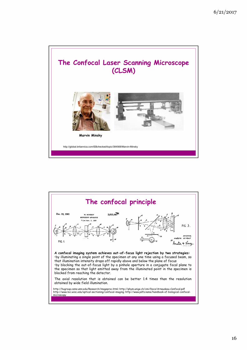
The Confocal Laser Scanning Microscope(CLSM)
http://global.britannica.com/EBchecked/topic/384568/Marvin-Minsky
Marvin Minsky
The confocal principle
http://hugroup.cems.umn.edu/Research/imageproc.html; http://phym.unige.ch/cmi/Docs/Arnaudeau-Confocal.pdfhttp://www.loci.wisc.edu/optical-sectioning/confocal-imaging; http://www.pdfs.name/handbook-of-biological-confocal-microscopy
A confocal imaging system achieves out-of-focus light rejection by two strategies:•by illuminating a single point of the specimen at any one time using a focused beam, sothat illumination intensity drops off rapidly above and below the plane of focus•by blocking the out-of-focus light by a pinhole aperture in a conjugate focal plane tothe specimen so that light emitted away from the illuminated point in the specimen isblocked from reaching the detector.
The axial resolution that is obtained can be better 1.4 times than the resolutionobtained by wide field illumination.

6/21/2017
17
Specimen scanning versus laser scanning
Advantage of specimen scanning is that the field of view can be large and all points in the image are illuminated under the same angle. Dissadvantage, image acquisition is slow.
Dissadvantage of single point scanning is that all points are illuminated under different angles, and the maximum field of view is limited in size. Advantage, image acquisition is fast.
http://web.media.mit.edu/~minsky/papers/ConfocalMemoir.htmlAmos WB, White JG. How the confocal laser scanning microscope entered biological research. Biol Cell. 2003 95:335-42.http://onlinelibrary.wiley.com.proxy.kib.ki.se/doi/10.1016/S0248-4900(03)00078-9/pdf
The confocal laser scanning microscope (CLSM)
Prototype CLSM at the MRC Laboratory of Molecular Biology in 1986

6/21/2017
18
Confocal microscope
LSM510-ConfoCor2

6/21/2017
19
Raster scanning
Image acquisitionLaser point scanning Spinning (Nipkow) disc
http://micro.magnet.fsu.edu/primer/techniques/confocal/confocalintroduction.htmlhttp://zeiss-campus.magnet.fsu.edu/tutorials/spinningdisk/yokogawa/index.html
Diffraction of light & Abbe’s theory of image formation
http://www.osa-opn.org/home/articles/volume_18/issue_2/features/ernst_abbe_and_the_foundation_of_scientific_micros /#.Up-biBDVbagE. Abbe. Beiträge zur Theorie des Mikroskops und der Mikroskopischen Wahrnehmung. Archiv für Mikroskopische Anatomie, IX, 413-68 (1873).
• The object AB when illuminated with coherent light, diffracts the light. • The different orders of diffraction collected by the lens are separated in
the back focal plane of the objective lens. • Diffracted orders interfere in the image plane, forming the image B'A‘.
• The smallest separation that can be resolved (d) depends on the wavelength of the illumination light in vacuum (λ), one half of the angular aperture of the microscope objective (α) and the refractive index of the immersion medium (n).
2sin
nd

6/21/2017
20
Diffraction effects, aberrations in the opticalsystem and detector noise will spread the imageof a point source captured by a confocalmicroscope over a finite area.
Irradiance distribution in an image of a pointsource is called the point spread function (PSF).
Resolution limit imposed by diffraction
Resolution of a diffraction-limited optical microscope
NAR
2
22.1 Radial resolution
Axial resolution22
64.0
NAnnZ
Numerical aperture (NA)
2sin
nNA
n – refractive index of the immersion medium
Resolution in confocal microscopy
Angular aperture of a lens is the apparent angle of the lens aperture as seen from the focal point.
f – focal length
D –diameter of the aperture
f
Darctg
22

6/21/2017
21
Improving the resolution of fluorescence microscopy
Improving the axial resolution
•Total Internal Reflection (TIRF) Microscopy• Light Sheet Fluorescence Microscopy (LSFM)• Single Plane Illumination Microscopy (SPIM)• 2-Photon excitation Microscopy (2-PEM)
Evading the diffraction limit – Super-resolutionfluorescence imaging techniques
• Structured Illumination Microscopy (SIM)• Fluorescence Imaging with One Nanometer Accuracy (FIONA)• Stochastic Optical Reconstruction Microscopy (STORM)• (Fluorescence) Photoactivation Localization Microscopy ((f)PALM)•Stimulated Emission Depletion (STED) Microscopy
http://www.youtube.com/watch?v=UCJ6oQSdxN0
http://www.microscopyu.com/articles/fluorescence/tirf/tirfintro.html
Total Internal Reflection (TIRF) Microscopy

6/21/2017
22
Light Sheet Fluorescence Microscopy (LSFM)
Philipp J. Keller, Annette D. Schmidt, Joachim Wittbrodt, Ernst H. K. Stelzer. Reconstruction of Zebrafish Early Embryonic Development by Scanned Light Sheet Microscopy. Science, 2008, Science. 2008 322(5904):1065-9
Improved axial resolution
Single Plane Illumination Microscopy (SPIM)
http://www.dkfz.de/Macromol/research/spim.html

6/21/2017
23
http://www.microscopyu.com/articles/fluorescence/multiphoton/images/multiphotonintrofigure1.jpg
2-Photon Excitation Microscopy (2-PEM)
http://belfield.cos.ucf.edu/image/Gallery/on%20vs%20two/fluorescein.jpghttp://microscopy.duke.edu/introtomicroscopy/twophotonex.html
2-photon excitation requires a pulsed laser to enable excitation via the two step process (the half-waystate is very short lived so the second photon needs to act very soon after the first), necessitatingfemtosecond pulsed laser.Radial resolution of 2-PEM is somewhat lower than the radial resolution of single-photon excitationbecause of the longer wavelength of the excitation beam, whereas axial resolution and penetrationdepth are signifficantly improved.
2-Photon vs 1-photon absorption

6/21/2017
24
http://www.mathematik.com/Moire/Gustaffson MGL. Surpassing the lateral resolution limit by a factor of two using structured illumination microscopy. Journal of Microscopy 2000,198:82-87Gustafsson MGL. Nonlinear structured-illumination microscopy: wide-field fluorescence imaging with theoretically unlimited resolution. Proc Natl Acad Sci U S A 2005, 102:13081-13086.
Structured Illumination Microscopy (SIM)
Moiré effect is a visual perception that occurs when viewing patterns that are superimposed on each other, which differ in relative size, angle, or spacing.
By superimposing the images of a low spatial frequency pattern or a grid and the object, information that exists beyond the resolving power of a fluorescent microscope can be revealed.
This technique can offer at least a doubling of spatial resolution, and in the presence of nonlinear saturation effects, can theoretically offer unlimited resolution.
Gustafsson MGL PNAS 2005;102:13081-13086 http://www.allthebestbits.net/structured-illumination-microscopy/
Epifluorescence Confocal SIM
290 nm 210 nm 130 nm
Spatial resolution of SIM

6/21/2017
25
Nobel prize for chemistry 2014
For making it possible to see features at thescale of billionths of a meter, smashing atheoretical barrier for optical microscopy.
Eric Betzig Stefan Hell William Moerner
Yildiz A, Selvin PR.Fluorescence imaging with one nanometer accuracy: application to molecular motors. Acc Chem Res. 2005 Jul;38(7):574-82.http://link.springer.com.proxy.kib.ki.se/content/pdf/10.1007%2F978-1-61779-261-8_4
si – standard deviation of the Gaussian distribution (PSF width/2.2)a – the effective pixel size of the detector, which is equal to thepixel size divided by magnificationb – backgroundN – number of collected photons
Single molecules can be localized with an arbitrary high precision by increasing the signal-to-noise ratio (SNR)!
The signal-to-noise ratio (SNR) in a digital image
photon noisepixelation effect due to thefinite pixel size of the detector
background
N2

6/21/2017
26
Fluorescence Imaging with One Nanometer Accuracy (FIONA)
Determining the center, i.e. the mean value of the photon distribution (μ = x0,y0), and its uncertainty, the standard error of the mean, σ.
If 10,000 photons can be collected in the absence of background before the fluorophore bleaches or is switched off, the center of localization can be determined with an accuracy of approximately 1 to 2 nanometers.!
Yildiz A, Selvin PR.Fluorescence imaging with one nanometer accuracy: application to molecular motors. Acc Chem Res. 2005 Jul;38(7):574-82.http://www.youtube.com/watch?v=Bom9d-Knz0w
Stochastic Optical Reconstruction Microscopy (STORM)
Rust MJ, Bates M, Zhuang X: Sub-diffraction-limit imaging by stochastic optical reconstruction microscopy (STORM). Nat Methods 2006, 3:793-796.B. Huang, M. Bates & X. Zhuang, Annu. Rev. Biochem., 78, 993-1016 (2009). http://huanglab.ucsf.edu/STORM.jpgChurchman S, Okten Z, Rock RS, Dawson JF, Spudich SA. Single molecule high-resolution colocalization of Cy3 and Cy5 attached to macromolecules measures intramolecular distances through time. PNAS, 2005, 102: 1419–1423.https://www.youtube.com/watch?v=w2Qo__sppcI

6/21/2017
27
Photoactivatable GFP
Photoconversion in wild-type GFP is thought to involve a shift in the chromophore population from the neutral phenolic form to the anionic phenolate form. Rotation of the T203 and decarboxylation of glutamic acid 222 (E222) are structural rearrangements that may be key features of GFP photoconversion. Native (filled circles) and photoactivated (open squares) absorbance spectra of (B) WEGFP (wild-type EGFP) and (C) T203H mutant (PA-GFP) are shown normalized to the highest absorbance. (D) Emission spectra were collected under excitation at 475 nm of photoactivated WEGFP (green circles) and PA-GFP (red triangles).
Patterson GH, Lippincott-Schwartz J. A Photoactivatable GFP for Selective Photolabeling of Proteins and Cells. Science, 2002, 297:1873-1877; http://www.youtube.com/watch?v=Bom9d-Knz0w
2D and 3D STORM with nanometer-scale resolution
Huang B, Jones SA, Brandenburg B, Zhuang X. Whole cell 3D STORM reveals interactions between cellular structures with nanometer-scale resolution. Nat Methods. 2008 December ; 5(12): 1047–1052.

6/21/2017
28
Opioid receptor lateral organization by pcPALM
Dr. Tijana Jovanović-TalismanCity of Hope Beckman Research Institute Duarte, CA 91010, USA
Sengupta P, Jovanovic-Talisman T, Skoko D, Renz M, Veatch SL, Lippincott-Schwartz J. Probing protein heterogeneity in the plasma membrane using PALM and pair correlation analysis. Nat Methods. 2011 8:969-975.
.
Nanoscopic distribution of endogenous MOP in MDA-MB-468 cells
Nanoscopic distribution of endogenousMOP in MDA-MB-468 cells using anti-MOP antibody (ab64746) labeled withCage-552 fluorescent dye (Abberior)
Tobin et al. PLoS One 2014 9(2):e87225 V. N. Belov et al., "Rhodamines NN: A Novel Class of Caged Fluorescent Dyes", Angew. Chem. Int. Ed. 2010 49:3520−3523

6/21/2017
29
Stimulated Emission Depletion (STED) Microscopy
Donnert G, Eggeling C, Hell S. Major signal increase in fluorescence microscopy through dark-state relaxation. Nature Methods 2007, 40: 81-86; http://universe-review.ca/R13-11-QuantumComputing.htm
http://www.whatsnextnetwork.com/technology/media/sted_microscopy.jpgWillig KI, Harke B, Medda R, Hell SW. STED microscopy with continuous wave beams. Nature Methods, 2007, 4: 915-918
Spatial resolution of STED Microscopy

6/21/2017
30
Schermelleh et al. A guide to super-resolution fluorescence microscopy, J. Cell Biol. 2010 190:165–175
Resolvable volumes obtained with current commercial super-resolution microscopes
Limitations of super-resolution methods
Low temporal resolution of STORM and PALM, several milliseconds at best but most often in the minutes range
High excitation intensity – STED ~ 50 MW cm-2, 2-PEM ~ GW cm-2
Single-photon ~ 100 kW cm-2
Perturbation effects - singlet oxygen evolution and local overheating