flow in a pipe of rectangular cross-section - royal...
TRANSCRIPT

691
By R. J. Co r n ish , M.Sc., Assistant Lecturer in Engineering in the Universityof Manchester.
(Communicated by E. A. Milne, F.R.S.—Received June 22, 1928.)
List of Symbols,
a = half width of pipe in centimetres. b = hah depth of pipe in centimetres.
m = hydraulic mean depth = - T .a + b
p = pressure.Q = quantity of water in cubic centimetres per second.R = resistance per unit area in dynes per square centimetre.S = average velocity in centimetres per second. .t = temperature.w = velocity of a particle parallel to the axis of the pipe.2 = distance parallel to the axis of the pipe,p = density.H = absolute viscosity. v — kinematic viscosity.
Note,— R X (area of walls) = (difference of pressure) X (area of cross-seotion). Hence
R . 4 (a + b) dx = — dp . 4ab ; or R = — m .dz
Object o f Research ,The object of the research was to investigate the flow of water in a pipe of
rectangular cross-section. Much work has been done on similar problems with pipes of circular section,* and pipes of rectangular section have been investigated by Frommf and Davies and White. J Fromm worked with pipes in which the ratio of the sides was never less than 6 to 1 ; his report deals only with turbulent flow. In the case of Davies and White’s research, the minimum ratio of the sides was 40 to 1, so that the laminar flow could be calculated from the formula for flow between infinitely wide parallel plates.
The present writer used a pipe of section 1*178 cms. by 0*4:04 cms. (ratio of sides = 2*92) ; this presents a fresh problem where stream line flow is concerned, and shows interesting results in the region of the critical velocity.
* See especially Stanton and Pannell, ‘ Phil. Trans.,5 A, vol. 214, p. 199 (1914). t ‘ Z. f. ang. Math. Mech.,5 vol. 3, p. 339 (1923).J ‘ Roy. Soc. Proc.,5 A, vol. 119, p. 92 (1918).
Flow in a P ipe o f Rectangular Cross-Section.
VOL. OXX.— A. 3 n
on August 20, 2018http://rspa.royalsocietypublishing.org/Downloaded from
692 R. J. Cornish.
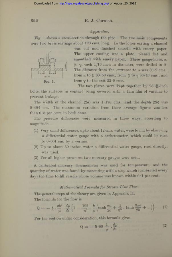
Apparatus.Fig. 1 shows a cross-section through the pipe. The two main components
were two brass castings about 120 cms. long. In the lower casting a channelwas cut and finished smooth with emery paper. The upper casting was a plate, planed flat and smoothed with emery paper. Three gauge-holes, a, (3, y, each 1/16 inch in diameter, were drilled in it. The distance from the entrance to a was 30*2 cms., from a to (3 30*50 cms., from [3 to y 36*43 cms., and from y to the exit 22*8 cms.
The two plates were kept together by 28 -^--incli bolts, the surfaces in contact being covered with a thin film of vaseline to prevent leakage.
The width of the channel (2a) was 1*178 cms., and the depth (26) was 0*404 cm. The maximum variation from these average figures was less than 0*5 per cent, in both cases.
The pressure differences were measured in three ways, according to magnitude—
(1) Very small differences, up to about 12 cms. water, were found by observinga differential water gauge with a cathetometer, which could be read to 0*001 cm. by a vernier.
(2) Up to about 30 inches water a differential water gauge, read directly,was used.
(3) For all higher pressures two mercury gauges were used.
A calibrated mercury thermometer was used for temperature, and the quantity of water was found by measuring with a stop watch (calibrated every day) the time to fill vessels whose volume was known within 0*1 per cent.
F ig . 1.
Mathematical Formula for Stream Line Fioiv.The general steps of the theory are given in Appendix II. The formula for the flow is
n ____a iQ 3 ‘ (x '
192^5 l ( t an h g + i . t an h | 2 + . -)} (1)
For the section under consideration, this formula gives
Q = — 5-08 1 dp (x dz
on August 20, 2018http://rspa.royalsocietypublishing.org/Downloaded from

Now m = 0-150 cm., and A = 0-476 sq. cm. ; using the relations Q = AS and R = — m . dp/dz, we easily find from (2) that
Flow in Pipe o f Rectangular Cross-Section. 693
(3)
Results.The results have been divided into two series, and are detailed in Appendix
I. Series 1 includes readings taken at gauge holes a and y and the readings of series 2 w ere taken at (3 and y. In fig. 2 log (R/pS2) has been plotted against log (mS/v).
The observed equation for the stream line portion is
The coefficient was found by averaging separately the first 10 readings of series 1 and the first five of series 2. In both cases the average was 2 -10. The difference between this value and the theoretical value 2-12 (see equation (3)) is easily accounted for by slight errors in measuring so small a channel.
In calculating the values of R/pS2 andmS/v, p was assumed to be 1 and p was found from the formula
p = 0-017928/(1 + 0 • 034452 + 0-000235Z2),* where t is measured in degrees Centigrade.
Conclusions.1. Equations (2) and (3) are confirmed by the experiments.2. The effect of the distance of the gauge-holes from the entrance is well-
marked. Even with an entrance length of 400 m, as is the case with gauge- hole [3, the curve shows a departure from the stream line curve as the critical value of mS/v is approached. The conclusions of Davies and Whitef from a similar result are referred to below.
3. The critical value of mS/v for pipes of rectangular section is in the same region as that for pipes of circular section. In fig. 2, additional laminar flow curves have been drawn for a square section and for a section of infinite width. Prom the position of these curves one would expect the critical value of mS/v to increase as the ratio a to b increases. This is borne out by a comparison of the author’s results with those of Davies and White.
* Hosking, ‘ Phil. Mag.,’ vol. 18, p. 262 (1909). t ‘ Roy. Soc. Proc.,’ A, vol. 119, p. 96 (1928).
3 b 2
on August 20, 2018http://rspa.royalsocietypublishing.org/Downloaded from

R. J. Cornish.
T T -1 /J
*8 20
2-2
2-4
2-
6 2-8
30
3-2
3*
4 3-6
3*8
40
4-2
. 2.
—0
Ser
ies
1. -f
Ser
ies
2.
Dot
ted
lines
sho
w S
tant
on a
nd P
anne
ll’s
Cur
ves
for
Dra
wn
Bras
s Pi
pes.
Cha
in-d
otte
d lin
es
1It
1
*1----/
y/ / / /
/*/
i/ / i i i/i
// .
i/
// / / /
/ / / / / ?
// ♦ /
/ •/•0
# '
/// >\
//y -i.
V)E
/// / 11
]•®v / f
o°
i /: V
yy&
fr
\/ y h - y*/ /
/ 7V
/
/ y/ />/
/ /__ ' />/
/ /c /
---- 7*7
/>/
//
/ 7>/
/s
/ - ? //
/ /V
/y —
/y
y //
< ' // ZS dy/a ?<n
r $ C \ i O C O * 9 +
ICVJ IC \I K \ J ICO , c O , n ^ l c r
l ~ o
d0*-g<D1g)
PH
s00C2
1TSflce
egQ*o'w
on August 20, 2018http://rspa.royalsocietypublishing.org/Downloaded from
Flow in Pipe o f Rectangular Cross-Section. 695
4. When turbulent flow is fully established, the curve connecting R/pS2 and mS/v approximately coincides with that for drawn brass pipes ;* this is in agreement with the work of many investigators on smooth channels and pipes of various sections.
Note.—The conclusions of Davies and White referred to above appear to the writer to call for some discussion. They deduce a third critical value of mS/v, below which “ eddies cannot be transmitted to, or exist in, the channel.”f There is mathematical evidence for believing that there exists a critical velocity below which “ every disturbance must automatically d ec r ea se , and above which “ it is possible to prescribe a disturbance which will increase for a time.7’J This, of course, is a very different critical velocity from that found by Davies and White, and it could not be detected by their method, the essence of which is that below a certain value of mS/v a gauge point just inside the entrance wxould register steady flow under all conditions.
The experimental evidence which leads them to their conclusion is shown in figs. 3 and 4 of their paper. The present writer has been led from his own work on flow through narrow passages to consider that the dotted curves of their fig. 3 are tangential, or perhaps asymptotic, to the curve for Fl([iv[d), and the points of their fig. 3 would fit in quite well with this view. If this opinion is correct, it would seem to be difficult to find definite values from which to draw their fig. 4.
* Stanton and Pannell, loc. cit. f c Roy. Soc. Proc.,’ A, vol. 119, p. 99 (1928).X Orr, 6 Proc. Roy. Irish Acad.,’ A, vol. 27, p. 77 (1907).
on August 20, 2018http://rspa.royalsocietypublishing.org/Downloaded from

696 R. J. Cornish.
A p p e n d ix I .
Series 1.
Temperature ° F. S. dp . R. mS / v. R/pS2.
5 7 1 5-28 0 -400 cms. water 0-880 67-4 0-031656-9 5-54 0-401 „ 0-882 70-5 0-028856-7 5-83 0-442 ,, 0-972 73-9 0-0287,56-6 6-18 0-460 „ 1-012 78-2 0-026652-7 7-76 0-601 „ 1-321 92-8 0-022056-3 8*29 0-648 „ 1-425 104-7 0-020856*4 8-80 0-67 „ 1-47 111-3 0-019156-9 10-89 0-817 „ 1-796 138-5 0*0151657-2 11-42 0-860 ,, 1-891 146-0 0*0145253 1 16-57 1-290 „ 2-837 198-9 0-0103452-9 16-76 1-322 „ 2-907 201 0-0103652-4 28-9 2-399 „ 5-276 343 0-0063252-4 29-4 2-450 „ 5-388 350 0-0062251 -6 39-6 3*47 „ 7-63 465 0-0048658-7 38-3 3-15 „ 6-93 501 0-0047258-7 40-2 3*29 „ 7-23 525 0-0044958*7 42-5 3-54 „ 7-78 556 0-0043249*3 54-8 5-96 „ 13-10 621 0-0043756-8 49-9 5-09 „ 11*19 635 0-0045057*0 49-9 5-10 „ 11-22 636 0*0045253 1 61-1 8-08 ,, 17*77 733 0*0047849-2 69-9 10*78 „ 23-7 788 0-004875 1 0 70-4 11-01 „ 24-2 817 0-0049150 0 81-1 5-56 ins. water 31*0 929 0-004735 6 1 79-4 13-52 cms. water 29-7 999 0-0047256*4 79-4 13*54 ,, 29-8 1005 0-0047349*8 107-5 9-21 ins. water 51*4 1225 0*0044649-8 143-9 15-45 „ 86-3 1642 0-0041850-5 168-5 20*32 „ 113-5 1945 0-0040150-5 186-3 24-25 „ 135-4 2150 0-0039151-0 215 31-20 „ 174-2 2500 0-003784 9 0 304 4*33 ins. Hg 329 3430 0-0035548-9 449 8*59 „ 652 5050 0-0032448-8 582 13-46 „ 1022 6530 0-0030248*8 • 742 20-81 „ 1580 8330 0-0028749-0 745 20-85 „ 1583 8400 0-0028548-8 764 21-70 „ 1650 8580 0-0028348*6 927 30-58 „ 2322 10370 0-0027148-7 939 30-91 ,, 2347 10520 0-0026648-8 942 31-12 „ 2363 10570 0-0026749 1 952 32-00 „ 2430 10740 0-0026955*2 1074 38-7 ,, 2940 13320 0-002565 4 0 1131 43-0 „ 3260 13760 0-0025654*2 1150 43-9 ,, 3330 14040 0 * 0025354 * 6 1285 53-4 ,, 4050 15810 0-0024654*9 1290 53-9 „ 4090 15930 0-00247
on August 20, 2018http://rspa.royalsocietypublishing.org/Downloaded from

Flow in Pipe o f Rectangular Cross-Section. 697
Series 2.
Temperature°F. S. dp. R. m S/v . R/pS2.
55-7 7-17 0-297 cms. water 1-199 89-7 0-023555-5 7-32 0-299 »> 1-208 91-4 0-022656-6 12-21 0-510 >> 2-060 154-8 0-013954-3 18-48 0-820 j) 3-312 238 0-0087454-9 20-4 0-852 11 3-441 251 0-0083156-3 29-6 1-261 11 5-093 374 0-0058055-2 33-2 1-433 5-788 412 0-0052554*5 35-6 1-551 6-264 438 0-0049353*9 40-4 1-793 7-242 491 0-004455S-9 40-8 1-696 11 6-850 535 0-0041258-9 40-9 1-692 11 6-834 536 0-0041059*5 41-1 1-722 11 6-955 544 0-0041359-7 45-0 0-81 ins. water 8-3 598 0-0041159-7 45-2 0-81 91 8-3 600 0-0040759-7 45-5 0-82 11 8-4 604 0-0040859*6 45-6 2-03 cms. water 8-20 604 0-0039659-5 48-0 2-49 J y 10-06 635 0-0043759-5 46-9 1-13 ins. water 11-6 659 0-0046959-5 46-9 1-10 i i 11-3 659 0-0045759-5 46-6 2-84 cms. water 11-47 663 0-0045859-1 53-8 3-50 i i 14-13 707 0-0049058*7 67-4 5-49 i i 22-2 881 0-0048959-7 94-3 9-81 11 39-6 1250 0-0044749-8 110-5 5-26 ins. water 54-0 1260 0-0044456-2 100-4 11-22 cms. water 45-3 1264 0-0045149-4 157-8 10-00 ins. water 102-6 1789 0-0041349-6 184-1 13-19 yy 135-4 2096 0-0040149-8 195-9 14-75 yy 151-4 2240 0-0039651-9 197-6 14-83 yy 152-1 2330 0-0039151*7 224 18-31 y y 187-9 2620 0-0037851-5 255 23-44 yy 240-5 2990 0-0036951-5 265 24-90 yy 255-5 3100 0-0036451-5 272 26-20 y y 268-8 3190 0-0036348-9 449 4-71 ins. Hg. 657 5050 0-0032648-8 764 11-84 y y 1651 8580 0-0028348-8 942 17-01 yy 2373 10570 0-00268
Appen d ix II.
Theoretical Formula for Stream Line Flow.Take the origin of co-ordinates at the centre of the
cross-section, Ox parallel to the longer side, 0y parallel to the shorter side, and 0 z parallel to the axis of the pipe. (See fig. 3.)
The general equations of motion reduce to
y
A B
* b0 a *b
0 C
Fig. 3.
dpdx
= 0, dp _dy
0, w
on August 20, 2018http://rspa.royalsocietypublishing.org/Downloaded from

698 R. J. Cornish.
The first two equations show that the pressure is constant over the section.
Let t = — and w = y + t ( h 2 + ?/2).
Substituting in (6), we have
<»>
The object of introducing y is to simplify the boundary conditions.Along the boundary
x + T (b2 — y2 = w = 0. (6)Hence, along AB, CD,
X = 0 , ( 7 )and along AD, BC
x = — T (62 — (8)From (7) all the terms in y must vanish when y = ± b. This condition is satisfied by terms such as
(2n + 1) izy 2b 97] COS
where 7} is a function of x only and n is an integer.Substitute y — tj cos my in (5).
Thend2/,8a;2
m2yj = 0,
whence7) = Ancosh mx + B„ sinh
(9)
( 10)
( 11)
By symmetry about 0 y,BK = 0 ; hence
7) = A„ cosh mx,
and 7 consists of terms like A„ cosh mx cos my, where m = (2 + 1)-12b.These terms must now be made to satisfy the other boundary condition
(equation (8)). For convenience, let
y = 260/tc. (12)Then
X 2 Ab cosh ~ cos (2 + 1)6.2b
Substituting from (12) in (8), we have
X = t . 4 (62 — | t-2)/tc2.
(13)
(14)
on August 20, 2018http://rspa.royalsocietypublishing.org/Downloaded from

Flow in Pipe o f Rectangular Cross-Section. 699
This must agree with (17) when x = + a, i.e., with
+ 00 a + 1 ) r:0’ / 0 i \ aX — 2 cosh—----- -—■■■-...cos (2w + 1) 6.n=Q 2 6
(15)
Expanding (14) in a Fourier’s Series, we have 32 t62
X |cos 6 — . cos 36 + ^ . cos 56 ...j. (16)
Comparing coefficients in (15) and (16), we obtain A0, Av etc., whence we find_ 32 t62 (cosh (to/26) tuy cosh (3to/26) 3ruy \ n -
t:3 Icosh ++26) 2b 33 cosh (3tc+26) * 26 ’/Hence... _ 32t62 fcosh (tct/26) cq;: izy 1 cosh (3to/26) 3m/ , )
7 [cosh (to7:/26) ' 26 33’ cosh (3raz/26) " 26 *"j
The total flow is given by+b rx = + a
Q = w dx dy.J y= — b J x— — a
+ r (6*-</*). (18)
(19)
The integration of the terms in (18) is a straightforward matter, and gives finally
^ ^ f m 6 / ^ 1 t o \ l* 5 IX dz { TZ6 a \ 26 1 35 26
This formula is substantially equivalent to that for the torsion of a rod of rectangular section; see, for example, Prescott’s “ Applied Elasticity,” p. 148 (1924), where approximate methods of summing the series for particular cases are given.
Two Special Cases.(i) a — b.
It can easily be shown by differentiation of equation (24) that, for a given area, the square is the form of rectangular section giving the maximum flow for a given pressure difference. To find the flow in this case, put a = b in (20).
ThenQ = - 0-562 - + . (21)[i. dz
Since Q = 4a2S, a = m, and R = — m . djijdz, we get
on August 20, 2018http://rspa.royalsocietypublishing.org/Downloaded from

700 Flo w in Pipe o f Rectangular Cross-Section.
(ii) “ a ” infinite ; “ 6 ” finite. When a is large, (24) becomes approximately
whenceQ
S iL4 ah
ab3
•£ {* — 0-630-}, aJ (23)
- > — , » 3 • ~
dp. - - as a -* oo . dz (24)
But m = abj(a + 6) & as a -> o° .We therefore arrive at the standard formula for flow between two infinite
parallel plates, viz.,m2 dp mR (25)
orR _ o V
pS2 ~ mS# (26)
FZow m Opew Channels.In the case of laminar flow in an open rectangular channel of width 2a and
depth 6, the velocity gradient perpendicular to the surface is zero, if the air resistance be neglected. The flow is therefore one-half that in a pipe of rectangular section, 2a by 26, and the formula is
Q =2 oF dp U3 rjt dz l
192 b_ tz5 * a
t-anh H + ±tanh87za (27)
The author acknowledges with thanks the valuable assistance he has obtained from Dr. Prescott’s “ Applied Elasticity,” and from Prof. E. A. Milne, F.R.S., of Manchester University, in working out the above proofs.
on August 20, 2018http://rspa.royalsocietypublishing.org/Downloaded from