on mobile assemblies of bennett linkages - royal...
TRANSCRIPT

on July 7, 2018http://rspa.royalsocietypublishing.org/Downloaded from
On mobile assemblies of Bennett linkages
BY Y. CHEN1
AND Z. YOU2,*
1School of Mechanical and Aerospace Engineering, Nanyang TechnologicalUniversity, Singapore 639798, Republic of Singapore
2Department of Engineering Science, University of Oxford, Oxford OX1 3PJ, UK
This paper deals with deployable structures formed by interconnected Bennett linkages.A total of eight cases that allow mobile assemblies of Bennett linkages being built have beenfound by considering the links that may contain sections with negative length. Among theeight assemblies, four are distinct ones, including the one that we reported previously, andthe remaining can be obtained by modifying the four cases. All these assemblies consist of agrid of nested Bennett linkages. The layout of the assemblies can be repeated to form a largedeployable structure. When the Bennett linkages are equilateral, the assemblies expand toform arches. For a non-equilateral case, the assemblies deploy into a helical shape with acylindrical profile. They are geometrically overconstrained with a single degree of mobility.The newly found assemblies provide more choices in the design of deployable structures.
Keywords: Bennett linkage; overconstrained mechanism; mobile assembly;deployable structure
*A
RecAcc
1. Introduction
The Bennett linkage (Bennett 1903, 1914) is a 4R spatial overconstrained linkagein which four rigid links are connected by four revolute joints (R) forming aclosed loop. The axes of revolute joints are neither parallel nor concurrent to eachother. In general, seven links are required to achieve a single degree of mobilityfor a loop assembly, according to the Kutzbach criterion (Beggs 1966). With onlyfour links, the Bennett linkage is regarded as overconstrained and is the onlyknown mobile linkage with a minimum number of links. Since its discovery,many publications have been dedicated to this remarkable linkage. One of theresearch focuses has been on the mathematical description and the kinematiccharacters of the linkage. For instance, Ho (1978) presented an approach toestablish the geometric criteria for the existence of the Bennett linkage throughthe use of tensor analysis. Yu (1981) found that the links of the Bennett linkagewere in fact two pairs of equal and opposite sides of a line symmetricaltetrahedron. Baker (1988) investigated the J-hyperboloid defined by the jointaxes of the Bennett linkage and the L-hyperboloid defined by the links of theBennett linkage. More recently, Huang (1997) showed that the screw axes of allpossible coupler displacements of the linkage from any given configuration form acylindroid. The other research focus is to construct 5R and 6R overconstrained
Proc. R. Soc. A (2008) 464, 1275–1293
doi:10.1098/rspa.2007.0188
Published online 19 February 2008
uthor for correspondence ([email protected]).
eived 23 August 2007epted 23 January 2008 1275 This journal is q 2008 The Royal Society

(a) (b)
(d )(c)
Figure 1. (a–c ) Expansion sequence of an assembly based on the Bennett linkage and (d) thesectional view of the assembly.
Y. Chen and Z. You1276
on July 7, 2018http://rspa.royalsocietypublishing.org/Downloaded from
linkages by merging several Bennett linkages. The most noticeable examplesinclude the Myard linkage (Myard 1931), the Goldberg 5R and 6R linkages(Goldberg 1943), the Waldron hybrid linkage (Waldron 1968), the Bennett-joint6R linkage (Mavroidis & Roth 1994), the Dietmaier 6R linkage (Dietmaier 1995)and Wohlhart’s double-Goldberg linkages (Wohlhart 1991). These linkages stillretain the single degree of freedom as the original Bennett linkage. A summarywas provided by Chen (2003).
A few years ago, we reported the discovery of a family of mobile assembliesbased on the Bennett linkage (Chen & You 2005). The findings allow us toconstruct not only a large mobile grid with an arch or spiral profile, but alsotowers, as well as more complex mobile assemblies, all of which are over-constrained with a single degree of mobility. One such structure is shown infigure 1.
This paper is a continuation of our previous work. We have discovered that itis possible to obtain new assemblies of Bennett linkages by considering thatsections of a link may have a negative length. All of our findings have beenverified by physical models. The new assemblies provide a much large scope inthe design of deployable structures for civil and aerospace applications.
The layout of the paper is as follows. Section 2 gives a brief introduction ofBennett linkage and its basic assembly. In §3, we define the negative link lengthand, by adopting such lengths, several new assemblies can be derived from thebasic ones. The comparisons among the various assemblies are discussed in §4.Finally, the conclusions and further discussion are given in §5.
Proc. R. Soc. A (2008)

Z4
Z1Z2
Z4
a34
a41
a12
a23
(a)(b)
Z1X4
X1
X2
X3
12
3
Z3
Z3
Z2
4
1
2
3
2
1
4
23
41
34
Figure 2. (a) A Bennett linkage and (b) its schematic.
1277On mobile assemblies of Bennett linkages
on July 7, 2018http://rspa.royalsocietypublishing.org/Downloaded from
2. Bennett linkages and the basic assembly
We call the mobile assemblies that were discovered previously the basicassemblies. To understand how they are constructed, it is necessary to reviewbriefly the conditions for a 4R Bennett linkage to have a single degree ofmobility. Let us build a Bennett linkage in which each of the links is normal tothe axes of the two revolute joints it bridges. Thus, the length of a link istherefore defined as the distance between the axes and the twist as the skewedangle between the axes. The linkage is shown in figure 2a, whose link lengths aretherefore a12, a23, a34 and a41 as well as twists a12, a23, a34 and a41. To define thepositive sense for these parameters, a coordinate system at each joint needs to beset up. To do so, we first let Zi be the axes of revolute joint j ( jZ1, 2, 3 and 4). Xj
is the axis normal to both Zj and ZjC1, positively from joints j to jC1 (when jC1becomes 5, it is replaced by 1). aj jC1 is the distance between axes Zj and ZjC1,which is also referred to as the length of link from joints j to jC1. aj jC1 is thetwist of the same link, which is the angle from axes Zj to ZjC1 positively about Xj.In figure 2a, axis //Zj, which is parallel to Zj, is drawn at joint jC1 in grey sothat the twist can be shown clearly. The motion of the linkage is determined bykinematic variables qj, which is the angle of rotation from XjK1 to Xj positivelyabout Zj (when subscript jK1Z0, it is replaced by 4).
The mobility conditions are as follows (Beggs 1966).
(a) Two alternate links have the same length and the same twist, i.e.
a12 Z a34 Z a; a23 Z a41 Z b; ð2:1aÞ
a12 Za34 Za; a23 Za41 Zb: ð2:1bÞ
(b) Lengths and twists should satisfy the condition
sin a
aZ
sin b
b: ð2:1cÞ
Proc. R. Soc. A (2008)
Y. Chen and Z. You1278
on July 7, 2018http://rspa.royalsocietypublishing.org/Downloaded from
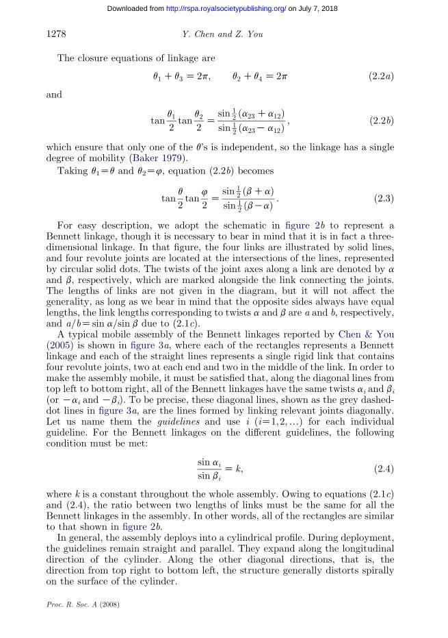
The closure equations of linkage are
q1 Cq3 Z 2p; q2 Cq4 Z 2p ð2:2aÞ
and
tanq1
2tan
q2
2Z
sin 12 ða23Ca12Þ
sin 12 ða23Ka12Þ
; ð2:2bÞ
which ensure that only one of the q’s is independent, so the linkage has a singledegree of mobility (Baker 1979).
Taking q1Zq and q2Z4, equation (2.2b) becomes
tanq
2tan
4
2Z
sin 12 ðbCaÞ
sin 12 ðbKaÞ
: ð2:3Þ
For easy description, we adopt the schematic in figure 2b to represent aBennett linkage, though it is necessary to bear in mind that it is in fact a three-dimensional linkage. In that figure, the four links are illustrated by solid lines,and four revolute joints are located at the intersections of the lines, representedby circular solid dots. The twists of the joint axes along a link are denoted by aand b, respectively, which are marked alongside the link connecting the joints.The lengths of links are not given in the diagram, but it will not affect thegenerality, as long as we bear in mind that the opposite sides always have equallengths, the link lengths corresponding to twists a and b are a and b, respectively,and a=bZsin a=sin b due to (2.1c).
A typical mobile assembly of the Bennett linkages reported by Chen & You(2005) is shown in figure 3a, where each of the rectangles represents a Bennettlinkage and each of the straight lines represents a single rigid link that containsfour revolute joints, two at each end and two in the middle of the link. In order tomake the assembly mobile, it must be satisfied that, along the diagonal lines fromtop left to bottom right, all of the Bennett linkages have the same twists ai and bi(or Kai and Kbi). To be precise, these diagonal lines, shown as the grey dashed-dot lines in figure 3a, are the lines formed by linking relevant joints diagonally.Let us name them the guidelines and use i (iZ1,2,.) for each individualguideline. For the Bennett linkages on the different guidelines, the followingcondition must be met:
sin ai
sin biZ k; ð2:4Þ
where k is a constant throughout the whole assembly. Owing to equations (2.1c)and (2.4), the ratio between two lengths of links must be the same for all theBennett linkages in the assembly. In other words, all of the rectangles are similarto that shown in figure 2b.
In general, the assembly deploys into a cylindrical profile. During deployment,the guidelines remain straight and parallel. They expand along the longitudinaldirection of the cylinder. Along the other diagonal directions, that is, thedirection from top right to bottom left, the structure generally distorts spirallyon the surface of the cylinder.
Proc. R. Soc. A (2008)

I4
I4
I4
I2
I2
I4
I4
I4
I4
I2
I4
I4
I4
I4
I4
I4
I4
–II5
–II5
–II5
II5
II5
II5
I6
I6I6
–II5 –II7
–II3
–II3
(a)
(b) (c)
II3
–II3
–II5
II5
–II5
–II3–II1
Figure 3. Schematic of assembly of similar Bennett linkages and its guidelines. (a) Whole assembly,(b) linkages on type I guideline and (c) linkages on type II guideline.
1279On mobile assemblies of Bennett linkages
on July 7, 2018http://rspa.royalsocietypublishing.org/Downloaded from
The guidelines can be further classified into type I and II lines. Along a type I line,all of the larger Bennett linkages, marked as Ii in figure 3b, are interconnected by thesmaller Bennett linkages. The twists must be the same for both the large and smallBennett linkages, which are denoted by ai and bi. Along a type II line, all of theBennett linkages, marked as IIi or KIIi in figure 3c, are connected through theircorners, sharing the two common links. The twists for the Bennett linkages are aiand bi orKai andKbi, alternating between the adjacent Bennett linkages. For theBennett linkages whose twists are Kai and Kbi, we denote them by KIIi.
3. The possible mobile assemblies
A typical link in the basic assembly, i.e. the assembly introduced in §2, hasfour revolute hinges. Denote the locations of the end joints by A, B, C and D, and
Proc. R. Soc. A (2008)

M N
Figure 4. Definition of the positive length.
Table 1. Eight possible cases for a three section link.a
case AB BC CD AD diagram of a linka
1 length sign C C C C
A B C D
–physical twist m n Kn m
2 length sign K C C C
B A C D
– + –physical twist Km n Kn m
3 length sign C C K C
A B
0
D Cphysical twist m n n m
4 length sign C K C C +
A C
0
B D
–physical twist m Kn Kn m
5 length sign K C K C –
B A D Cphysical twist Km n n m
6 length sign C K K C –
A D C Bphysical twist m Kn n m
7 length sign K K C C ––
C B A Dphysical twist Km Kn Kn m
8 length sign K K K K ––
D C B Aphysical twist Km Kn n Km
aThe twist marked on the link is the physical twist between two adjacent joints from left to rightalong the link.
Y. Chen and Z. You1280
on July 7, 2018http://rspa.royalsocietypublishing.org/Downloaded from
the shortest distances among the joints by AB, BC, CD and DA. These distancesare called the section lengths of a link. In the basic assembly, all of the lengthsare positive. However, this can be altered.
Before we embark upon deriving the formulae for new mobile assemblies, let usdefine the positive and negative length. First, assume the x -axis is collinear with alink (figure 4). Take two points, M and N on the x -axis with a positive direction. IfxNKxMO0, then length MN is positive. Meanwhile, the corresponding twist mMN isthe skew angle between the axes of the revolute joints at M to N positively aboutthe x -axis. If MN is negative, the corresponding twist becomes mNM or KmMN.
For any of the links in the basic assembly, commonly for twists there must beaAB ZaAD Zm and aBC ZKaCD Z n;
when AB, BC and CD are all positive, and m and n can be a’s or b’s, dependingon the locations of the link.
It has been discovered that the lengths can be positive as well as negative.There are totally eight (Z23) possible combinations of the sections with positiveand negative lengths, termed as cases 1–8, all of which are listed in table 1. Inorder to retain mobility, the twists need to be adjusted accordingly if some of thelengths become negative.
Proc. R. Soc. A (2008)

Figure 5. A typical Bennett linkage in a case 1 assembly.
1281On mobile assemblies of Bennett linkages
on July 7, 2018http://rspa.royalsocietypublishing.org/Downloaded from
Case 1. Case 1 is, in fact, the basic assembly. Consider a typical Bennett linkagein the assembly. It has four links, A1D1, A2D2, A3D3 and A4D4 that are connectedin such a way that D1 is connected with D2, A2 with A3, etc. (figure 5). To form anassembly, the top left corner of the Bennett linkage is connected to itsneighbouring Bennett linkage at B1 and B4, forming a smaller Ii linkage, as doesthe bottom right corner. At the top right and bottom left corners, it is alsoconnected with adjacent Bennett linkages, forming two smaller Bennett linkagesIIiK1 and IIiC1 with twists of either KaiK1 and KbiK1 or KaiC1 and KbiC1,respectively. A model is shown in figure 6 which demonstrates that the assemblyhas a single degree of mobility.
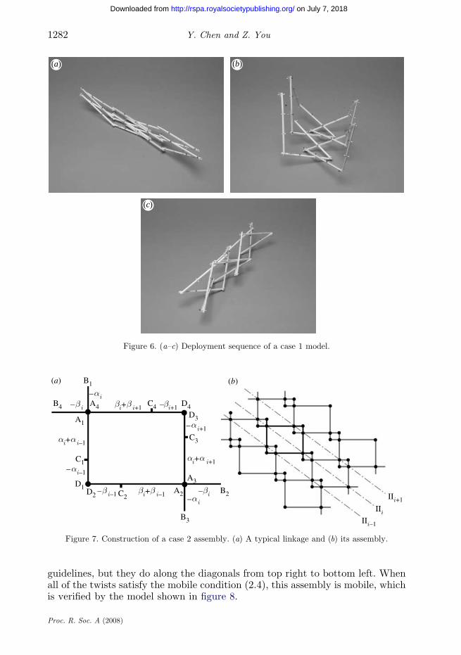
Case 2. In case 2, only section AB of a link has a negative length (table 1). Atypical Bennett linkage is shown in figure 7a, which is formed by connecting fourlinks at A’s and D’s. The twists of each link are as follows:
aA1D1ZKaB1A1
ZaA3D3ZKaB3A3
Zai;
aA2D2ZKaB2A2
ZaA4D4ZKaB4A4
Z bi;
)ð3:1aÞ
aB1C1ZKaC1D1
ZaiK1 and aB2C2ZKaC2D2
ZbiK1; ð3:1bÞ
aB3C3ZKaC3D3
ZaiC1 and aB4C4ZKaC4D4
ZbiC1: ð3:1cÞSimilar to the previous case, a number of small Bennett linkages are formed
through joints at B’s and C’s, and a complete assembly is shown in figure 7b.Owing to the particular twists given in (3.1a)–(3.1c), in this assembly, all of theguidelines are type II. The large Bennett linkages do not overlap along these
Proc. R. Soc. A (2008)
(a) (b)
(c)
Figure 6. (a–c) Deployment sequence of a case 1 model.
Figure 7. Construction of a case 2 assembly. (a) A typical linkage and (b) its assembly.
Y. Chen and Z. You1282
on July 7, 2018http://rspa.royalsocietypublishing.org/Downloaded from
guidelines, but they do along the diagonals from top right to bottom left. Whenall of the twists satisfy the mobile condition (2.4), this assembly is mobile, whichis verified by the model shown in figure 8.
Proc. R. Soc. A (2008)
(a) (b)
(c)
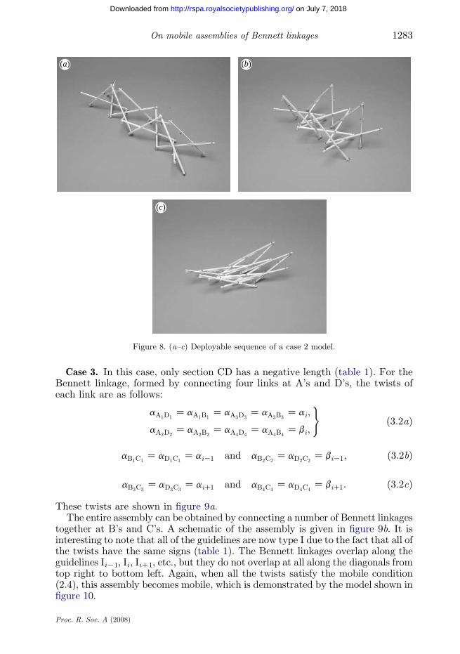
Figure 8. (a–c) Deployable sequence of a case 2 model.
1283On mobile assemblies of Bennett linkages
on July 7, 2018http://rspa.royalsocietypublishing.org/Downloaded from
Case 3. In this case, only section CD has a negative length (table 1). For theBennett linkage, formed by connecting four links at A’s and D’s, the twists ofeach link are as follows:
aA1D1ZaA1B1
ZaA3D3ZaA3B3
Zai;
aA2D2ZaA2B2
ZaA4D4ZaA4B4
Zbi;
)ð3:2aÞ
aB1C1ZaD1C1
ZaiK1 and aB2C2ZaD2C2
ZbiK1; ð3:2bÞ
aB3C3ZaD3C3
ZaiC1 and aB4C4ZaD4C4
ZbiC1: ð3:2cÞ
These twists are shown in figure 9a.The entire assembly can be obtained by connecting a number of Bennett linkages
together at B’s and C’s. A schematic of the assembly is given in figure 9b. It isinteresting to note that all of the guidelines are now type I due to the fact that all ofthe twists have the same signs (table 1). The Bennett linkages overlap along theguidelines IiK1, Ii, IiC1, etc., but they do not overlap at all along the diagonals fromtop right to bottom left. Again, when all the twists satisfy the mobile condition(2.4), this assembly becomes mobile, which is demonstrated by the model shown infigure 10.
Proc. R. Soc. A (2008)

Figure 9. Construction of a case 3 assembly. (a) A typical linkage and (b) its assembly.
Y. Chen and Z. You1284
on July 7, 2018http://rspa.royalsocietypublishing.org/Downloaded from
Case 4. The length of section BC is negative in this case. The correspondingtwists, listed in table 1, are given in figure 11a for the Bennett linkage obtainedby connecting at A’s and D’s. They are
aA1D1ZaA1B1
ZaA3D3ZaA3B3
Zai;
aA2D2ZaA2B2
ZaA4D4ZaA4B4
Zbi;
)ð3:3aÞ
aC1B1ZaC1D1
ZKaiK1 and aC2B2ZaC2D2
ZKbiK1; ð3:3bÞ
aC3B3ZaC3D3
ZKaiC1 and aC4B4ZaC4B4
ZKbiC1: ð3:3cÞ
A number of such linkages can be connected at B’s and C’s to form a largeassembly; however, the situation is a little more complex than the cases discussedearlier. Let us show how this is carried out by considering connections along theguidelines. Firstly, when a few linkages are connected at B’s, all of them stay onthe same type I diagonal, as shown in figure 11b. Note that at a few places thelinks cross over each other but they are not joined. These places therefore do nothave circular solid dots that have been used to indicate a hinged connection.Owing to (3.3a), the Bennett linkages overlap, forming some intermediate ones inbetween. All of the linkages have the same twists ai and bi along diagonal Ii.Secondly, when several linkages are connected at C’s, the assembly forms acurved profile in the diagonal direction from top right to bottom left (figure 11c).Again, some of the links cross over in the schematics, but they are, in fact, notjoined. Owing to (3.3b) and (3.3c), the linkages EFGH and PQST have twists ofKaiK1, KbiK1 and KaiC1, KbiC1, respectively. So when the linkages are joinedat both B’s and C’s, we obtain the assembly shown in figure 11d. Note that,although all of the guidelines are type I in the assembly, along IiK1, the linkagesEFGH and IJKL, as well as IMGN, have twists of KaiK1 and KbiK1 owing to(3.3b), and along IiC1, the linkages PQST and RUVW, as well as RXSY, havetwists of KaiC1 and KbiC1 owing to (3.3c). For all of the twists here that have anegative sign, the corresponding guidelines are type I instead of type II. When all
Proc. R. Soc. A (2008)

(a) (b)
(c)
Figure 10. (a–c) Deployable sequence of a case 3 model.
1285On mobile assemblies of Bennett linkages
on July 7, 2018http://rspa.royalsocietypublishing.org/Downloaded from
the twists meet the mobile condition (2.4), this assembly becomes mobile (see themodel in figure 12). However, owing to the large overlap, there could be conflictsduring the deployment. For example, the corners Q and H in the centre of theassembly in figure 11c may be in collision with each other. But the same is nottrue for the similar corners in figure 11b, because the overlap of two Bennettlinkages are connected along a type Ii guideline in which one of the corners movesup, whereas the other goes down during deployment. This feature has been usedby Chen & You (2005) to construct multilayer assemblies.
Cases 5–8. The assemblies of cases 5–7 are shown in figures 13–15, in which thetypical Bennett linkage is drawn in black. They all have type I and II guidelinesaltered from one to another. The largest Bennett linkages in the assemblies incases 5–7 are the same as the typical Bennett linkage in case 1. But, the placeswhere the linkages are connected with the neighbouring ones are different becausethe negative section lengths have switched A, B, C or D. If we regard the largestrectangles in the assemblies as the typical Bennett linkage instead, the threeassemblies based on cases 5–7 are similar to that in case 1.
For case 8, the lengths of all of the sections are negative, which are symmetricto case 1 where the direction of the guidelines is altered from top right to bottomleft (figure 16).
Proc. R. Soc. A (2008)
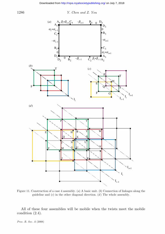
Figure 11. Construction of a case 4 assembly. (a) A basic unit. (b) Connection of linkages along theguideline and (c) in the other diagonal direction. (d ) The whole assembly.
Y. Chen and Z. You1286
on July 7, 2018http://rspa.royalsocietypublishing.org/Downloaded from
All of these four assemblies will be mobile when the twists meet the mobilecondition (2.4).
Proc. R. Soc. A (2008)

(a) (b)
(c)
Figure 12. (a–c) Deployable sequence of a case 4 model.
1287On mobile assemblies of Bennett linkages
on July 7, 2018http://rspa.royalsocietypublishing.org/Downloaded from
4. Comparison of different assemblies
Although a total of eight cases have been presented in §3, not all of them areindependent. Considering the twists along a single link, it can be found that the orderof twists along a single link for cases 5–8 is the same as the one for case 1 after suitablevariable substitution (table 1). Moreover, the largest Bennett linkages in theassemblies based on cases 5–8, represented by the largest rectangles in figures 13–16,are also similar to those in case 1. Hence, only cases 1–4 are independent.
In general, all of the assemblies of cases 1–8 deploy spirally to form acylindrical profile. The helical shape is determined by the dimension of thetypical Bennett linkage whose property is determined by (2.1a)–(2.1c). If aOb,the assembly deploys to a left-handed helical, whereas if a!b, it deploys to aright-handed one. When aZb, it forms an arch. The guidelines remain straightand parallel all the time. In this section, the geometry of four distinct assembliesof cases 1–4 will be compared.
In order to make a meaningful comparison of four assemblies, the followinggeometric preconditions are set up to make the total length of links in theassemblies equal to each other.
(i) Each assembly consists of nine typical Bennett linkages arranged three ina row with three rows in total (figure 17a). Smaller intermediate Bennettlinkages are not accounted for here.
Proc. R. Soc. A (2008)

B1
A1D1
C1
Figure 13. A case 5 assembly.
A1
D1
C1
B1
Figure 14. A case 6 assembly.
Y. Chen and Z. You1288
on July 7, 2018http://rspa.royalsocietypublishing.org/Downloaded from
(ii) The lengths of the links in the typical Bennett linkages are a and b. Eachlink is divided into three equal sections, with section lengths being a/3and b/3, respectively.
(iii) The twists of each Bennett linkage are either a and b or Ka and Kb. Thelengths and twists satisfy the geometric condition of the Bennett linkage(2.1c) and mobility condition for the assemblies (2.4).
Based on the above preconditions, the distance between two rows along theguideline, l, and the radius of the cylindrical profile, r, can be calculated. Both land r are indicated in figure 17a,b, respectively.
To obtain l and r, we need to study the geometry of a typical Bennett linkage inthree-dimensional space first. Figure 18a shows a Bennett linkage ABCD beingplaced on a cylindrical surface in such a way that A, B, C and D are on the surface
Proc. R. Soc. A (2008)

A1
C1
B1
D1
Figure 15. A case 7 assembly.
Figure 16. A case 8 assembly.
1289On mobile assemblies of Bennett linkages
on July 7, 2018http://rspa.royalsocietypublishing.org/Downloaded from
and lineBD,which is collinearwith a guideline, is along the longitudinal direction ofthe cylinder. According to the precondition, the geometric parameter of Bennettlinkage ABCD is
aAB Z aCD Z a; aAD Z aBC Z b;
aAB ZaCD Za; aAD ZaBC Z b:
Its kinematic variables, q and 4, are given in figure 18a. The cross-sectional view ofthe linkage on the cylinder is given in figure 18b, in which the angle between planesABD and BCD is denoted by x. Take l0 as the length BD. In DABD,
l 0 ZBDZffiffiffiffiffiffiffiffiffiffiffiffiffiffiffiffiffiffiffiffiffiffiffiffiffiffiffiffiffiffiffiffiffiffiffiffiffiffiffiffia2 Cb2C2ab cos q
p: ð4:1Þ
Proc. R. Soc. A (2008)

(a) (b)
Figure 17. (a) Key geometrical parameters of an assembly. (b) The cross-sectional view.
A
DE C
2p–j
F
A CB/F/E/D
B
q
x
(a) (b)
Figure 18. The geometry of a single Bennett linkage. (a) On the surface of a cylinder and (b) thecross-section view.
Y. Chen and Z. You1290
on July 7, 2018http://rspa.royalsocietypublishing.org/Downloaded from
Denote the radius of this cylinder by r0,
r0 Z1
2
AF
cos x
2
Z1
2
CE
cos x
2
;
where both AF and CE are equal and perpendicular to BD. Considering DABD orDCBD, we have
AFZCEZab sin qffiffiffiffiffiffiffiffiffiffiffiffiffiffiffiffiffiffiffiffiffiffiffiffiffiffiffiffiffiffiffiffiffiffiffiffiffiffiffiffi
a2 Cb2C2ab cos qp :
Hence, from figure 18b,
cos xZKðcos 4Ccos qÞða2 Cb2 C2ab cos qÞ
ab sin2qK1;
Proc. R. Soc. A (2008)

2.0
(a)
1.5
1.0
0.5
(b)
2.5
2.0
1.5
1.0
0.5
00
Figure 19. The geometrical parameters of a Bennett linkage when aZp/3. (a) l0/a versus q and(b) r0/a versus q for various b/a.
1291On mobile assemblies of Bennett linkages
on July 7, 2018http://rspa.royalsocietypublishing.org/Downloaded from
so
r0 Zab sin2q
2ða2 Cb2 C2ab cos qÞ
ffiffiffiffiffiffiffiffiffiffiffiffiffiffiffiffiffiffiffiffiffiffiffiffiffiffiffiffiK2ab
cos qCcos 4
s: ð4:2Þ
Based on (4.1) and (4.2),we canplot l0/a and r0/aversus deployedangle q curves.Figure 19 shows such curves for aZp/3.
A few observations can be made from the diagram. Firstly, when b/aZ1, that is,the Bennett linkage is an equilateral one, there are two folded configurations: l0Z0,qZp and r0Z0, qZ0. The deployment starts from a compact bundle with r0Z0,expands to an intermediate arch profile and finally ends when the assembly folds flatwith l0Z0. Secondly, both the overall length and the radius of assembly changemoredramatically when b/a is closer to 1. Thirdly, for assemblies made from non-equilateral Bennett linkages, when q changes from 0 to p, l0 decreases, whereas r0increases from 0 to a maximum value and then falls back to 0 again.
For each case, it is possible to establish the relationships among geometricparameters, l and r, of the assemblies, and l0 and r0 for the single linkage, whichare listed in table 2. It is obvious that overall longitudinal length of the assemblyand the radius of cylindrical profile formed by the assembly are proportional to l0and r0, respectively, despite the fact that the proportion is different. Theassembly of case 4 has the most compact profile, whereas the assembly of case 2is the longest in the longitudinal direction. The assembly of case 3 offers thecylindrical profile with the largest radius, while that of cases 2 and 4 is thesmallest. From our experience in making physical models, it is learnt thatthe assemblies with smaller radius, for example, those based on cases 2 and 4, aremore likely to have conflict during the deployment, and the one with largerradius, for example, that of case 3, is much easier to be folded compactly.
5. Conclusions and discussion
In this paper, we have greatly extended our previous work on assemblies of Bennettlinkages, which was published in this journal (Chen & You 2005). In total, eightcases that allow mobile assemblies of Bennett linkages to be built have been
Proc. R. Soc. A (2008)
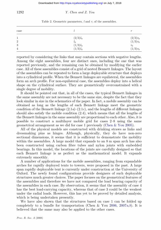
Table 2. Geometric parameters, l and r, of the assemblies.
case l r
1 (2/3)l 0 (2/3)r02 l0 (1/3)r03 (1/3)l 0 r04 (1/3)l 0 (1/3)r0
Y. Chen and Z. You1292
on July 7, 2018http://rspa.royalsocietypublishing.org/Downloaded from
reported by considering the links that may contain sections with negative lengths.Among the eight assemblies, four are distinct ones, including the one that wasreported previously, and the remaining can be obtained by modifying the earliercase. All of these assemblies consist of a grid of nested Bennett linkages. The layoutof the assemblies can be repeated to form a large deployable structure that deploysinto a cylindrical profile. When the Bennett linkages are equilateral, the assembliesform an arch profile. For non-equilateral case, the assemblies deploy into a helicalshape on the cylindrical surface. They are geometrically overconstrained with asingle degree of mobility.
It should be pointed out that, in all of the cases, the typical Bennett linkages inthe same assembly are not necessary to be the same size, despite the fact that theylook similar in size in the schematics of the paper. In fact, a mobile assembly can beobtained as long as the lengths of each Bennett linkage meet the geometriccondition of the Bennett linkage (2.1a)–(2.1c), and the lengths of different linkagesshould also satisfy the mobile condition (2.4), which means that all the lengths ofthe Bennett linkages in the same assembly are proportional to each other. Also, it ispossible to construct a multilayer mobile grid for cases 2–8 using the samegeometrical arrangement as we did for case 1 previously (Chen & You 2005).
All of the physical models are constructed with drinking straws as links anddressmaking pins as hinges. Although, physically, they do have non-zerosectional dimensions, it seems that it is sufficient to demonstrate the mobilitywithin the assemblies. A large model that expands to an 8 m span arch has alsobeen constructed using carbon fibre tubes and nylon joints with embeddedbearings. In this model, the locations of the joints are carefully designed so thateach Bennett linkage is as perfect as the mathematical model. It expandsextremely smoothly.
A number of applications for the mobile assemblies, ranging from expandablearches for rapidly deployed tents to towers, were proposed in the past. A largespan rapidly deployable tent is currently under construction at the University ofOxford. The newly found configurations provide designers of such deployablestructures much greater choices. The paper focuses on the geometrical features ofthe assemblies and therefore we have not compared the load bearing capacity ofthe assemblies in each case. By observation, it seems that the assembly of case 4has the best load-carrying capacity, whereas that of case 3 could be the weakestunder the radial loads. However, this has yet to be proved by detailed analysis,which is being undertaken presently.
We have also shown that the structures based on case 1 can be folded upcompletely to a bundle for transportation (Chen & You 2006, 2007a,b). It isbelieved that the same may also be applied to the other cases.
Proc. R. Soc. A (2008)

1293On mobile assemblies of Bennett linkages
on July 7, 2018http://rspa.royalsocietypublishing.org/Downloaded from
Y.C. would like to thank the Nanyang Technological University, Singapore, for providing aresearch grant (RG21/05) and subsequent academic leave to undertake work related to this article.Z.Y. would like to acknowledge financial support from the Engineering and Physical SciencesResearch Council (grant no. EP/E502903).
References
Baker, J. E. 1979 The Bennett, Goldberg and Myard linkages—in perspective. Mech. Mach.Theory 14, 239–253. (doi:10.1016/0094-114X(79)90011-9)
Baker, J. E. 1988 The Bennett linkage and its associated quadric surfaces. Mech. Mach. Theory23, 147–156. (doi:10.1016/0094-114X(88)90092-4)
Beggs, J. S. 1966 Advanced mechanism. New York, NY: Macmillan Company.Bennett, G. T. 1903 A new mechanism. Engineering 76, 777–778.Bennett, G. T. 1914 The skew isogram mechanism. Proc. Lond. Math. Soc. 13, 151–173. (doi:10.
1112/plms/s2-13.1.151)Chen, Y. 2003 Design of structural mechanism. DPhil (PhD) thesis, University of Oxford.Chen, Y. & You, Z. 2005 Mobile assemblies based on the Bennett linkage. Proc. R. Soc. A 461,
1229–1245. (doi:10.1098/rspa.2004.1383)Chen, Y. & You, Z. 2006 Square deployable frame for space application: part I: theory. Proc. Inst.
Mech. Eng. Part G: J. Aerosp. Eng. 220, 347–354. (doi:10.1243/09544100JAERO68)Chen, Y. & You, Z. 2007a Square deployable frame for space applications: part II: realisation.
Proc. Inst. Mech. Eng. Part G: J. Aerosp. Eng 221, 37–45. (doi:10.1243/09544100JAERO100)Chen, Y. & You, Z. 2007b Deployable frames with curved profile. In 48th AIAA/ASME/ASCE/
AHS/ASC Structures, Structural Dynamics and Material Conference and Exhibit, Hawaii, April2007, AIAA-2007-2115.
Dietmaier, P. 1995 A new 6R space mechanism. In Proc. 9th World Congress IFToMM, Milano,vol. 1, pp. 52–56.
Goldberg, M. 1943 New five-bar and six-bar linkages in three dimensions. Trans. ASME 65,649–663.
Ho, C. Y. 1978 Note on the existence of Bennett mechanism. Mech. Mach. Theory 13, 269–271.(doi:10.1016/0094-114X(78)90050-2)
Huang, C. 1997 The cylindroid associated with finite motions of the Bennett mechanism. Trans.ASME, J. Eng. Ind. 119, 521–524.
Mavroidis, C. & Roth, B. 1994 Analysis and synthesis of overconstrained mechanism. In Proc.1994 ASME Design Technical Conference, Minneapolis, MI, September, pp. 115–133.
Myard, F. E. 1931 Contribution a la geometrie des systemes articules. Societe Mathematiques deFrance 59, 183–210.
Waldron, K. J. 1968 Hybrid overconstrained linkages. J. Mech. 3, 73–78. (doi:10.1016/0022-2569(68)90016-5)
Wohlhart, K. 1991 Merging two general Goldberg 5R linkages to obtain a new 6R spacemechanism. Mech. Mach. Theory 26, 659–668. (doi:10.1016/0094-114X(91)90028-3)
Yu, H.-C. 1981 The Bennett linkage, its associated tetrahedron and the hyperboloid of its axes.Mech. Mach. Theory 16, 105–114. (doi:10.1016/0094-114X(81)90056-2)
Proc. R. Soc. A (2008)