floating lng: the challenges of production systems and well …€¦ · liquefied natural gas (lng...
TRANSCRIPT
1
17th INTERNATIONAL CONFERENCE & EXHIBITION ON
LIQUEFIED NATURAL GAS (LNG 17)
Floating LNG: The Challenges of production
systems and well fluids management By: Frederic MOLLARD, TECHNIP France
04/19/2013
17th INTERNATIONAL CONFERENCE & EXHIBITION ON LIQUEFIED NATURAL GAS (LNG 17)
Floating LNG: The challenges of production systems and well fluids management
Frederic MOLLARD - TECHNIP FRANCE
04/19/2013
2

Content
Introduction
FLNG presentation
Main dimensions and weight distribution
Operational Constraints
Well Fluids management
Introduction
Production Profiles
Temperature Profile
Pressure Profile
Sand and Produced Water
Production Systems
Receiving facilties – Control Strategy
Purpose
Condensate production systems
Conclusion
3
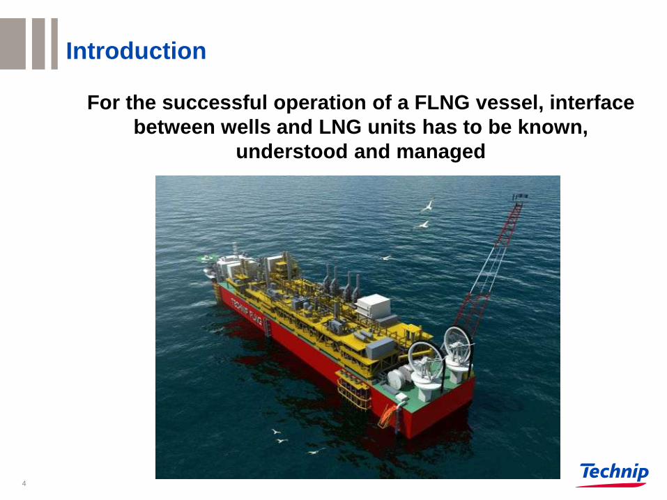
Introduction
For the successful operation of a FLNG vessel, interface
between wells and LNG units has to be known,
understood and managed
4
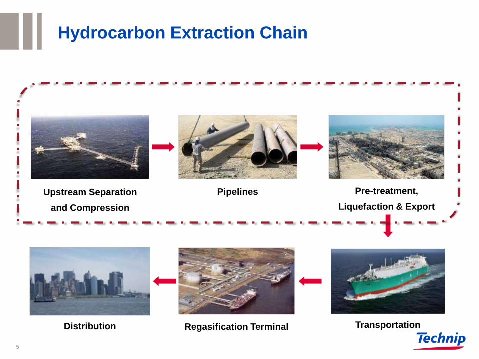
Upstream Separation
and Compression
Pre-treatment,
Liquefaction & Export
Transportation Regasification Terminal Distribution
Pipelines
Hydrocarbon Extraction Chain
5

Transportation Regasification Terminal Distribution
Upstream,
Pre-treatment,
Liquefaction & Export
Hydrocarbon Extraction Chain – FLNG example
6

7
Typical Offshore Oil extraction Field
7
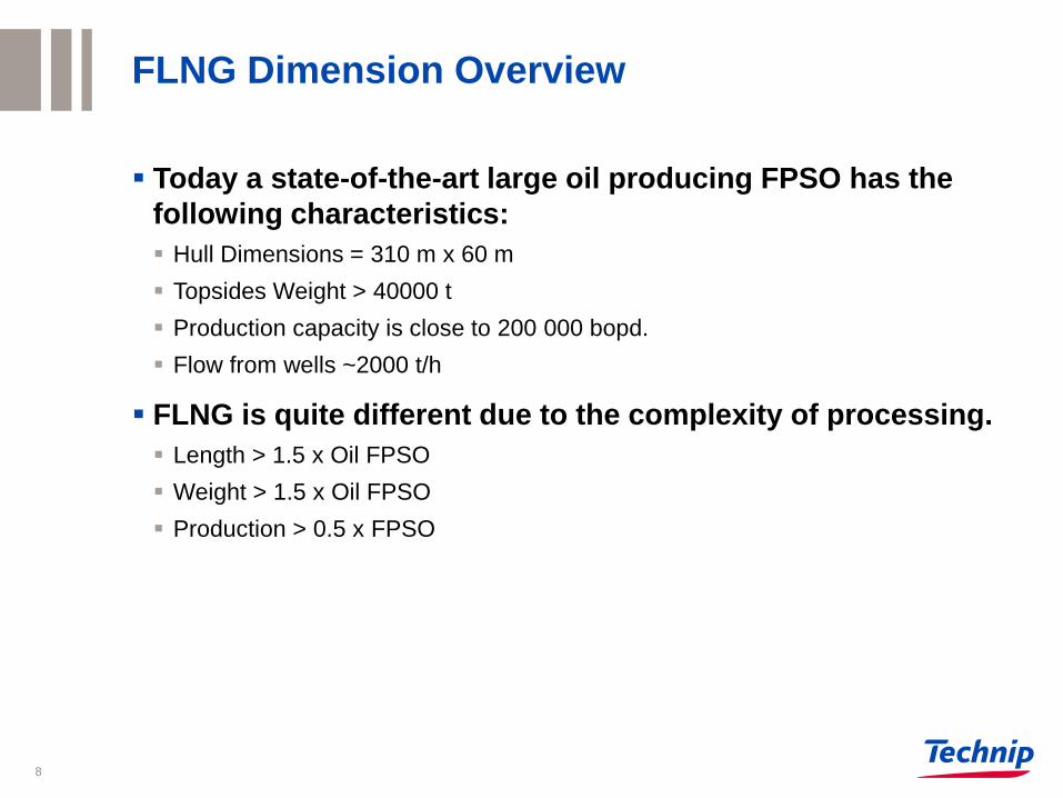
FLNG Dimension Overview
Today a state-of-the-art large oil producing FPSO has the
following characteristics:
Hull Dimensions = 310 m x 60 m
Topsides Weight > 40000 t
Production capacity is close to 200 000 bopd.
Flow from wells ~2000 t/h
FLNG is quite different due to the complexity of processing.
Length > 1.5 x Oil FPSO
Weight > 1.5 x Oil FPSO
Production > 0.5 x FPSO
8
Utility Production for the Plant
- Power Plant - Nitrogen Generation - Fire Fighting Systems
- Cooling water - Flare - Water Treatment
Acid Gas
disposal
Liquefaction
Well fluids
from
subsea
risers
LNG Storage
Fractionation
LPG Storage
& offloading
(if applicable)
Dehydration
Condensate
Stabilisation
Mercury
Removal
NGL
Extraction
Refrigeration
Refrigerant Make up/ LPG reinjection
LNG
offloading
Condensate
offloading
N2 Rejection Acid Gas
Removal Fuel gas
Condensate
Storage
Water
&
chemicals
Hydrate
Management
Inlet
separator
FLNG Units Description
9
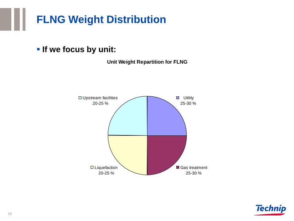
Unit Weight Repartition for FLNG
Gas treatment
25-30 %
Liquefaction
20-25 %
Upstream facilities
20-25 %
Utility
25-30 %
FLNG Weight Distribution
If we focus by unit:
10
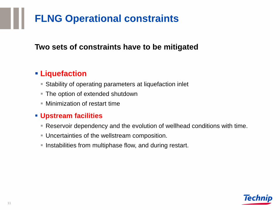
FLNG Operational constraints
Two sets of constraints have to be mitigated
Liquefaction
Stability of operating parameters at liquefaction inlet
The option of extended shutdown
Minimization of restart time
Upstream facilities
Reservoir dependency and the evolution of wellhead conditions with time.
Uncertainties of the wellstream composition.
Instabilities from multiphase flow, and during restart.
11

Well Fluid Management
Well fluids are characterized by the uncertainties:
Reservoir depletion over time leads to modification of pressure, temperature and
composition
Water break-through
Reservoir geology and drilling activities may cause pollution (sand, salts,
completions fluids, radioactive material, tracers, etc.)
In addition process parameters can be modified by
phenomena generated within the subsea architecture:
Seasonal cycles (seawater temperature)
Start-up or shutdown of wells
Flow regime in flowlines and risers
12
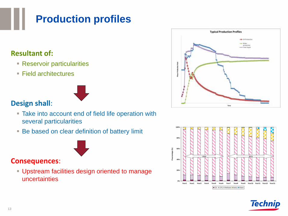
Production profiles
0%
20%
40%
60%
80%
100%
Year1 Year2 Year3 Year4 Year5 Year6 Year7 Year8 Year9 Year10 Year11 Year12 Year13
Po
urc
en
tag
e (
%)
C5+ LPG Methane Inerts Water
LEAN RICH
Resultant of:
Reservoir particularities
Field architectures
Design shall:
Take into account end of field life operation with
several particularities
Be based on clear definition of battery limit
Consequences:
Upstream facilities design oriented to manage
uncertainties
13

Temperature profile
Resultant of:
Reservoir particularities
Field architectures
Design shall :
Maintain stable conditions at LNG
Improve hydrate management
Consequences:
Hydrate inhibitor injection
Active heating Technology
14

Pressure profile
Resultant of:
Reservoir particularities,
Field architectures
Specific operation (start-up of wells)
Design shall:
Cope with WHSIP
Cover Potential reservoir depletion over field
life
Consequences:
Additional compression unit due to depletion
factors
High rating material in upstream facilities
15

Sand and produced water
Resultant of:
Reservoir particularities
Well operation
Design shall :
Be able to manage produced water and sands
Be able to remove salts from oil
Consequences:
Sand resistant material selection
Desanding system
Desalting system
16

Sand and produced water
Footer can be customized 17
4
2
5
Sandclean System
1
Gas
Oil
Produced
Wellfluids
Sand Jet
Water
Produced
Water
Sand
Disposal
3 6
Sand collection

Production systems
FLNG Receiving facilities control system challenges:
1. Protection of liquefaction unit
2. Safe Disposal of well fluids
3. Ensure Smooth liquefaction operation
Simple control and robust design
18
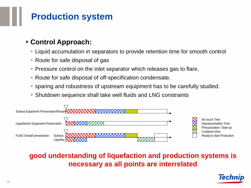
Production system
Control Approach:
Liquid accumulation in separators to provide retention time for smooth control
Route for safe disposal of gas
Pressure control on the inlet separator which releases gas to flare.
Route for safe disposal of off-specification condensate.
sparing and robustness of upstream equipment has to be carefully studied.
Shutdown sequence shall take well fluids and LNG constraints
good understanding of liquefaction and production systems is
necessary as all points are interrelated
Subsea Equipment Preservation/Restart
No touch Time
Liquefaction Equipment Preservation Depressurisation Time
Pressurization / Start-up
Cooldown time
FLNG Overall preseravtion Subsea Ready to Start Production
Liquefac.
19

Production system
Purpose:
Treat condensate / liquids to commercial specification or environmental
specification for disposal
Condensate Export Specifications Water Disposal Specification
RVP < 6 to 12 psi OIW content < 5 to 30 ppm
BSW < 0.5 to 2%
Salt content < 15 to 60 mg/l
H2S content < 1 to 10 ppm
Table 1. Standard Condensate and Water outlet specifications
20

Production system
Condensate Treatment Technologies
Separation of hydrocarbons and water to reach Base Sediment Water (BSW)
specification
Heating and separation to reach Reid Vapor Pressure (RVP) specification on
condensate product
Washing and purification to obtain H2S or Salt content
21
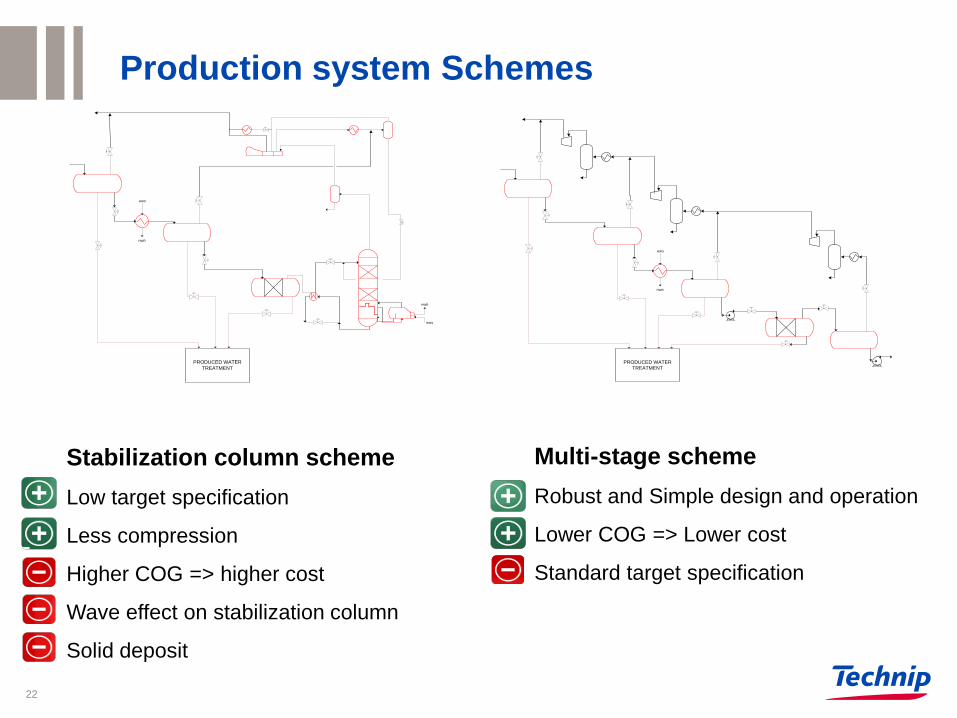
PRODUCED WATER
TREATMENT
HWS
HWR
HWS
HWR
HWS
HWR
PRODUCED WATER
TREATMENT
Stabilization column scheme
Low target specification
Less compression
Higher COG => higher cost
Wave effect on stabilization column
Solid deposit
Multi-stage scheme
Robust and Simple design and operation
Lower COG => Lower cost
Standard target specification
Production system Schemes
22

Conclusion
For the successful operation of a FLNG vessel, it is most
important to design the process from the wellhead to the
liquefaction unit. This implies the following:
Good understanding of reservoir characteristics
Good understanding of fluid behaviour from wellhead to topsides,
Simple, robust, flexible designs and easy to operate upstream
facilities
Smooth control of upstream facilities to stabilize process parameters
upstream of liquefaction unit.
23

www.technip.com
Thank you
24