flm d t i1cs, - defense technical information center · ýiiclassifjed s flm d t i1cs, s wt secrity...
TRANSCRIPT

ýiiclassifjed S flM D T I1CS,S WT SECRITY CLASSIFC1 ICAOPTHISM~ I.
n.ztP EUnclassifiCAdO 7b. RESTRICTIVE MARKINGS3 Lt
'ICURIY CLASIFICTION U= TY 3 J. STRIIUT1ONIAVAILA11IUTY OF REiPORT
ECLASOKAIONApproved for public releaselF~.DJD)%4A"SR 7 distribution is unlimited.
4. PIRFORMING ORGANIZATiON REPORT NLJMAER(S) 3. MONITORING OIRQANIZATI0O4 REPORT NUMEE9R(S)h
Astron Final Report Number 7151-001 AIOF -t~.k -71 - 59so. WWIIE Of PERFORMING ORGANIZATION 6eb. OFFICE SYPBOL. 7a. NAME OF MONITORING ORGANIZATION
Astron Research and Engineering OfAFkaie OSR/NA
6c-FAOORCSS (City, tafte and ZIP Codip 7b. ADDRESS (0y, Stfts, And ZIP Code)
Sunnyvale Calif ornia 94086 Building 410, Bolling AFB DC20332-6440
S.NAME OF F`JNOING/SPONSOR.ING 8b. OFFICE SYMBUIL- i. 9PROCUREMENT INSTRUMENT 1IONT1IACATION NUMBER
AFOS~NA NAF49620-88-C-0130
&L. ADDRESS (CJy, seits. and ZIP Code) 10. SOURCE OF FUNDING NUMBERS
Building 41.0, Bolling A.FB DC PROGRAMt PROJECT TASKo VRK UNIT
20332-6448 ELEMENT NO. NO. NO.ACEION..65502F 3005 Al 1 IEtON.
11. TITLE (Iftdu* Sucuf"t Qm*atim)
(U) Demonstration of Oblique Detonation Wave for Hypersonic Propulsion
I' Ta~s i taa"'a Michael J Schuh, Donald S Randall, Thomas J Dahm, David T Pratt
13a. 1TYPE OT REPOR 1/31/89Fitnal Technical -1/_/ r
1S. SUPPLEMENTARY NOTATION/
I7. COSATi COOES 1 S. SUBECT TERMS (CoAUVu on MVWm Peea~ and" bkw hAtc ulmb.'EO GRr JP SUB-RIOUP obli)ue) detonati.on wave, detonati.on, hyparsonic propulsion,
hypervelocity launcher, rain accelerator * 1)I _______
i 9. ABSTAT (Conantu OteF fUri and rQ*- if-~ -~95f L- 7%Ii'
The Oblitaue Detonation Wave Engine (OCDWE) offers a nulmiber of advantages over the Supersonic
co obtain data on the stability of thie Oblique Detonation Wave (0CM) and to assess theapplicability of the ODW to hypersonic propulsion. The program consists of the basic stud.yof the 01)W phenom~enon and the design study of the teSt facility (Phase 1), and an 2.ndepthexperimental study of the 0CM in a ram cannon-type ccrnbustion tube with a hypervelocityprojectile launched into the tube by a two-stage liqht-gas gun (Phase II). This Phase Itreport siimiurizes the results pertaining to the stability of the O0W and the experimentalfacility designs. It is concluded that the ODW will be initiated and sustained in the testfacility configuration and that the tests will generate data concerning 'key issues for theapplication of the ODW to hypersonic propulsion.
20 DISTRIIUTION/4VAILABIUITY OF ABSTRACT 21 ABSTRACT SECURITY CL.ASSIFICATION(MUNCLA$SIFIEO/UNLIMITIO C1 SAME AS RPT ] 0r1C tSERS Qnclassfiq
22a. NAME OF RESPONSIBLE INOI'VIOUAL 224 T PI I IULJulian M Tishkoft 20
00 Form 1473, JUN 34PF0,V#Q1JS V0010fi it' Ioo~f vS . SECURITY CLASSIPICITION OF 1wi'74GAE
8 6 0 1 0 42 Unclassified
t.PO6-Th. 89-06659
Preface -
This is the final report for the SBIR Phase I contractF49620-88-C-0130, "Demonstration of the Oblique Detonation Wave(ODW) for Hypersonic Propulsion," sponsored by the Air ForceOffice of Scientific Research (AFOSR). The program manager ofAFOSR was Dr. Julian Tishkoff, Directorate of Aerospace Science.This work was performed during the period Auaust 1988 to January1989 by Astron Research and Engineering, Sunnyvale, CA. Thepersonnel actively involved in this program were: Dr. TakashiNakamura (Principal Investigator) , Dr. Michael J. Schuh, Mr.Donald S. Randall, and Mr. Thomas J. Dahm. Professor David T.Pratt, University of Washington, conducted the comnutational fluiddynamic (CFD) work discussed in this report and supported theAstron team in conducting the basic analysis of the ODW.
An informal progress review of this program was held on 24January 1989 at NASA Lewis Research Center (LeRC) in which T.Nakamura and D.T. Pratt gave briefings on the program's progress.Dr. Edward J. Mularz, Propulsion Directorate at NASA LeRC, hostedthe meeting with Dr. Julian Tishkoff, who was visiting LeRC forthis occasion. Dr. Erwin Lezberg, Dr. Peter Sockol, and othermembers of LeRC who are actively involved in hyperson4 ý propulsionattended the meeting and provided us with valuable input inanalytical and experimental aspects of the prograat.
We are indebted to members of the Combustion ResearchFacility, Sandia National Laboratory, for their participation iiideveloping concepts for diagnostics and instrumentation. Ourspecial thanks go to Dr. Robert W. Dibble, Dr. Robert J.Cattolica, Dr. William L. Flower, and Dr. Robert S. Barlow formuch valuable discussion.
It is our gre-,t sorrow to have lost our colleague Mr. ThomasJ. Dahm on 22 February 1989. Mr. Dahrm, co-founder and Cnairman ofAstron, was the inventor of the Wave Gun and an active participantin this program. We miss his deep engineering insights and hisamicable nature which have been an encouragement and aninspiration to all of us. Although 'we feel deep sadness and agreat sense of loss, we are determined to move forward toundertake the tasks left to us.
ACCesiurn For
NTIS (RA&I
DTIC lAB UUnaiulo I.,' .yj L
By.
* DiJtibutiut I
A..,IceL .h C ';,WJs
v. I , Li'iu
Dt •
0
Cont~ents
SECTION 1 - INTRODUCTION . . . . . . . . . . . . . . . . . . . 1-1
SECTION 2 - ANALYSIS OF HYPERVELOCITY PROJECTILE TEST FLIGHT 2--1
* 2.1 FLOWFIELD SURROUNDING THE PROJECTILE ... ........ 2-1
2.2 THEORETICAL OVERVIEW ................ ................ 1
2.3 ONE-DIMENSIONAL FLOW ANLAYSIS ........ ............ 2-5
* 2.4 PARAMETRIC CALCULATIONS TO OBTAINOPTIMUM CONDITIONS ............ ................. 2-6
2.5 BOUNDARY LAYER THICKNESS PREDICTIONS .... ........ 2-11
2.6 HEAT TRANSFER PREDICTIONS ........ ............. 2-13
2.7 PROJECTILE THERMAL LOAD ........ .............. 2-16
SECTION 3 - DESIGN OF HYPERVELOCITY PROJECTILE ....... ........ 3-1
3.1 REQUIREMENTS FOR PROJECTILE .... ................. I-1
3.2 PROJECTILE DESIGNS ........ ..................... 3-1
3.2.1 Stage I Projectile Design ...... .......... 3-2
3.2.2 Stage II Projectile Design ... ......... 3-3
3.3 PROJECTILE FABRICATION ...... ................... 3-6
SECTION 4 - COMPUTATIONAL FLUID DYNAMIC (CFD) ANALYSIS OFTHE ODW STABILIZATION EXPERIMENT .... ........... 4-1
S4.1 INT:RODUCTION ...................................... 4-1
4.2 COMPUTATIONAL APPROACH ............................ 4-2
4.2.1 Development of a Time-Accurate TransientCE'D Code: E2D ............................ 4-2
4.2.2 Efficient Steady-State CFD Code: RPLUS2D .4-4
.3 COMPUTATIONAL RESULTS .......... ................ 4-5
5 4c..,ults with E2D ........ .............. 4-6
iv

4.3.2 Preliminary Results with RPLUS2D ... ...... 4-11
1.4 CONCLUSIONS FROM CFD ANALYSIS ..... ........... 4-22
4.5 PLANS FOR FUTURE WORK ........... ............... 4-23
SECTION 5 - DESIGN OF TEST FACILITY ......... ............. 5-1
5.1 WAVE GUN ................... ...................... 5-1
5.2 RECOIL ABSORBING JOINT ............... ........ 5-4
5.3 SABOT SEPARATION ........... ............... .... 5-4
5.3.1 Gas Venting ................. 5-6
5.3.2 Sabot Separation Section.. ...... .......... 5-8
5.3.3 Venting/Stripping Tube Construction . ... 5-10
5.4 OBLIQUE DETONATION WAVE TEST SECTION ..... ........ 5-11
5.5 GAS PRESSURE INTERFACES ......... .............. 5-15
5.6 STOPPER ASSEMBLY ............... .................. 5-17
5.7 GENERAL ASSEMBLY ................... .................. 5-i7
SECTION 6 - DIAGNOSTIC METHODS AND INSTRUMENTATION ........ 6-1
6,1 OVERVIEW OF DIAGNOSTIC METHODS ....... ........... 6-1
6.2 TIME OF ARRIVAL MEASUREMENTS ......... ............ 6-4
6.3 DYNAMIC PRESSURE MEASUREMENTS ........... 6-4
6.4 SPECTRALLY RESOLVED OPTICAL OBSERVATIONS ... ...... 6-8
6.4.1 OH Radical Emission Line Observation 6-9
6.4.2 Multi-Color Pyrometry. ........ ......... 6-10
6.5 SYNCHROBALbISTIC PHOTOGRAPHY (SBP) ..... ......... 6-10
6.6 EXTERNAL VELOCITY SCREENS ......... ............. 6-13
6.7 MICROWAVE DOPPLER VELOCITY MEASUREMENT ........ 6-14
6.8 DATA RECORDING ............... ................... G-16
SECTION 7 - EXPERIMENTAL PROCEDURE ........... .............. 7-1
7.1 TEST PLAN .................... ..................... 7-1
v

7.1.1 Stage I Experiments .7-2
7.1.2 Stage II Experiments ......... ....... 7-3
7.2 TEST SEQUENCE ............... ................... 7-4
"7.2.1 Preparation of Inert Components ........... 7-4
7.2.2 Wave Gun Preparation ........ 7-5
7.2.3 Test Section Filling ....... ............ 7--7
7.2.4 Arming and Firing ....... ........... .... 7-7
7.2.5 Refurbishment ........... ............... 7-8
SECTION S - SUAMARY AND CONCLUSION .......... .............. 8-1
8.1 SUMMARY OF THE RESULTS ........... ............... 8-1
8.2 CONCLUSIONS ................... .................... 8-3
vi
SECfION I - INTRODUCTTON
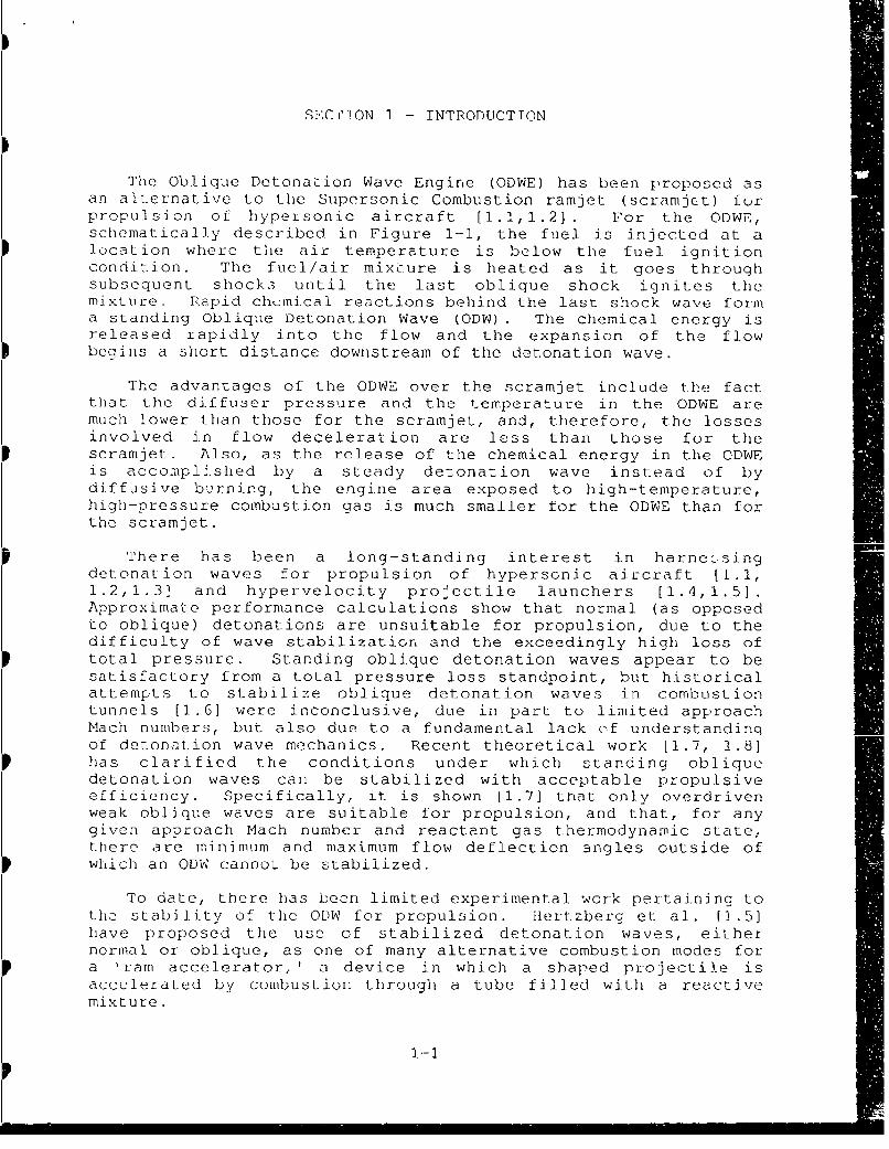
The Oblique Detonation Wave Engine (ODWE) has been proposed asan alternative to the Supersonic Combustion ramjet (scramjct) furpropulsion of hypersonic aircraft [1.1i,1.2]. For the ODWE,schematically described in Figure 1-1, the fuel is injected at alocation where tile air temperature is below the fuel ignitioncondition. The fuel/air mixbure is heated as it goes throughsubsequent shocks until the last oblique shock ignites themixture. Rapid chemical reactions behind the last shock wave forma standing Oblique Detonation Wave (ODW) . The chemical energy isreleased rapidly into the flow and the expansion of the flowbegins a short distance downstream of the detonation wave.
The advantages of the ODWE over the scramjet include the factthat the diffuser pressure and the temperature in the ODWE aremuch lower than those for the scramjet, and, therefore, the lossesinvolved in flow deceleration are less than those for thescramjet. Also, as the release of the chemical energy in the ODWEis accompl J.shed by a steady detonation wave instead of bydiffjsive burning, the engine area exposed to high-temperature,high-pressure combustion gas is much smaller for the ODWE than forthe scramjet.
There has been a long-standing interest in harnebsingdetonation waves for propulsion of hypersonic aircraft [i.1,1.2,1.3] and hypervelocity projectile launchers [1.4,1.5].Approximate performance calculations show that normal (as opposedto oblique) detonations are unsuitable for propulsion, due to thedifficulty of wave stabilization and the exceedingly high loss oftotal pressure. Standing oblique detonation waves appear to besatisfactory from a total pressure loss standpoint, but historicalattempts to stabilize oblique detonation waves in combustiontunnels [1.6] were inconclusive, due in part to limited approachMach numbers, but also due to a fundamental lack of understandinqof detonation wave mechanics. Recent theoretical work [1.7, 1.8]has clarified the conditions under which standing obliquedetonation waves can be stabilized with acceptable propulsiveefficiency. Specifically, it is shown [1.7] that only overdrivenweak oblique waves are suitable for propulsion, and that, for anygiven approach Mach number and reactant gas thermodynamic state,there are minimum and maximum flow deflection angles outside ofwhich an ODW cannot be stabilized.
To date, there has been limited experimental work pertaining tothe stability of the ODW for propulsion. ilertzberg et al. [1.5]have proposed the use of stabilized detonation waves, eithernormal or oblique, as one of many alternative combustion modes fora vram accelerator, ' a device in which a shaped projectile isaccelerated by combustion through a tube filled with a reactivemixture.
1.-1
* 01EII
u 4J
:< 0
00
(911
1-21
In aý series ot ox}tai itents using methane--oxygen mixtures, theylhave dcioonstrated the acceleration of projct liles (60 to 75 gram)from initial injection velocities in the ranoe of 900 m/s to 1200ii/s to final velocities of 1500 m/s to 1900 m/s.
The pýopulsion mechanism of this acceleration, however, wasthermally choked subsonic combustion and ' ot stabilized detonation[1. 9] . R cent ly, they were able to achieve acceleration ofprojectiles beyond this velocity range [I.101 . Sinco thisvelocity range is above the Chapma n-Jougu et velocity, thepro.pulsion mechanism is considered to be superderonative, whichinvolves ob~lique shock and associated combustion phenomena. Inthe case of their- results it 4s not clear whether the combustionprocess is shock-induced combustion or the oblique detonationwave. liert.berg and B1uckner stated thaL their test Projectileforebody was a 10' hall--angle cone [1.10) which, according to theanalysis of Pratt et al. [1.71, is too small to stabilize an ODW.Consequent ly, it ;s most likely that their observedsuperdetonatLive acceleration was due to shock-induced combustion.Unfortunately, the diagnostic methods used in their experiment donot provide sufficient data to determine the shock structure andthe combustion wave structure.
To gain better understanding of this important phenomena,Ast. uon Research anti Engineering proposed to conduct a theoreticaland expeoimmental study to investigate ODW phenomlena and to as';,sSthe applicability oi the O0W to hypersonic prepulsion. To achievethese goals in a direct and unambiguous way, we proposed toconduct the experiment in a ram cannon configuration using theWave Gun, a hypervelocity two-stage light-gas gun developed byAstron, to achieve the initial projectile velocity 2 .5 km/snecessary to initiate the ODW.
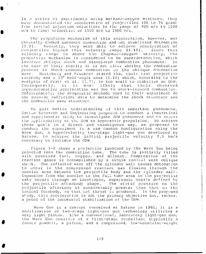
Figure 1-2 shows a projectile launched by the Wave Gun beinginjected into the combustion tube. The tube is initially filledwith premixed fuel, oxygen, and diluent . Compression of thereactant gases is accomplished by a single conical weak obliqueshock. The reflected wave off the cylinder wall causes detonationto occur in the compressed reactant gas flowing through theannular area between the projectile body and the cylinder wall.Expansion froom the annulus to the full tube area in the projectilewake occurs through an isentropic, supersonic nozzle defined bythe projectile afterbody shape. The static pressure on theprdjectile aftexbody is considerably greater than that on theconical forebody, so that riet, thrust is produced. In the proposedstudy, this acceleration is not the primary objective but, rather,a proof of the successful stabilization of the ODW.
Wave Gun is a concept conceived at Astron in 1981; it is amodification of two-stage light-gas gun technology utilizing avery light piston. Like a conventional, lauoratory light-gas gun,the Wave Gun consists of a first-stage( propellant (typically acarnn.n powder) , a piston, and a compressd, low-molecular-weight
1-3
CONICAL OBLIQUE OBLIQUE DETONATION WAVESHOCK E EXPANSION
NOZZLES~~~~PROJECTILE • INZZE
FUEL/OXYGENMIXTURE
Figure 1--2 Schematic or a Hypervelocity ProjectileInjected by the Wave Gun into a CombustionTube Filled with Premixed Fuel, Oxygen andD iluent
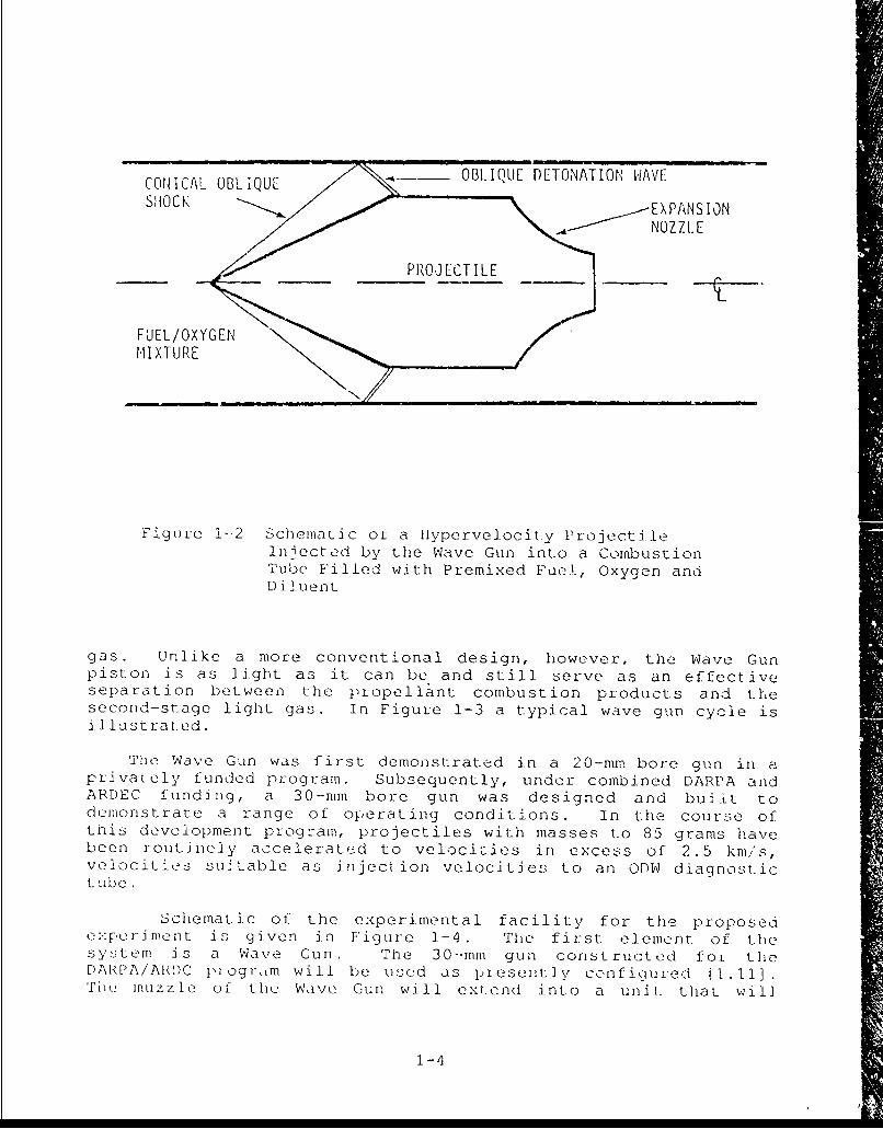
gas. Unlike a more conventional design, however, the Wave Gunpiston is as light as it can be and still serve as an effectiveseparation between the propellant combustion products and thesecond-stage light gas. In Figure 1-3 a typical wave gun cycle isillustrated.
The Wave Gun was first demonstrated in a 20-mm bore gun in aprivately funded program. Subsequently, under combined DARPA andARDEC funding, a 30-mm bore gun was designed and bulit todeimonstrare a range of operating conditions. In the course ofthis development program, projectiles with masses to 85 grams havebeen routinely accelerated to velocities in excess of 2.5 kmi/s,velocities suitable as injection velocities to an ODW diagno-:tictube.
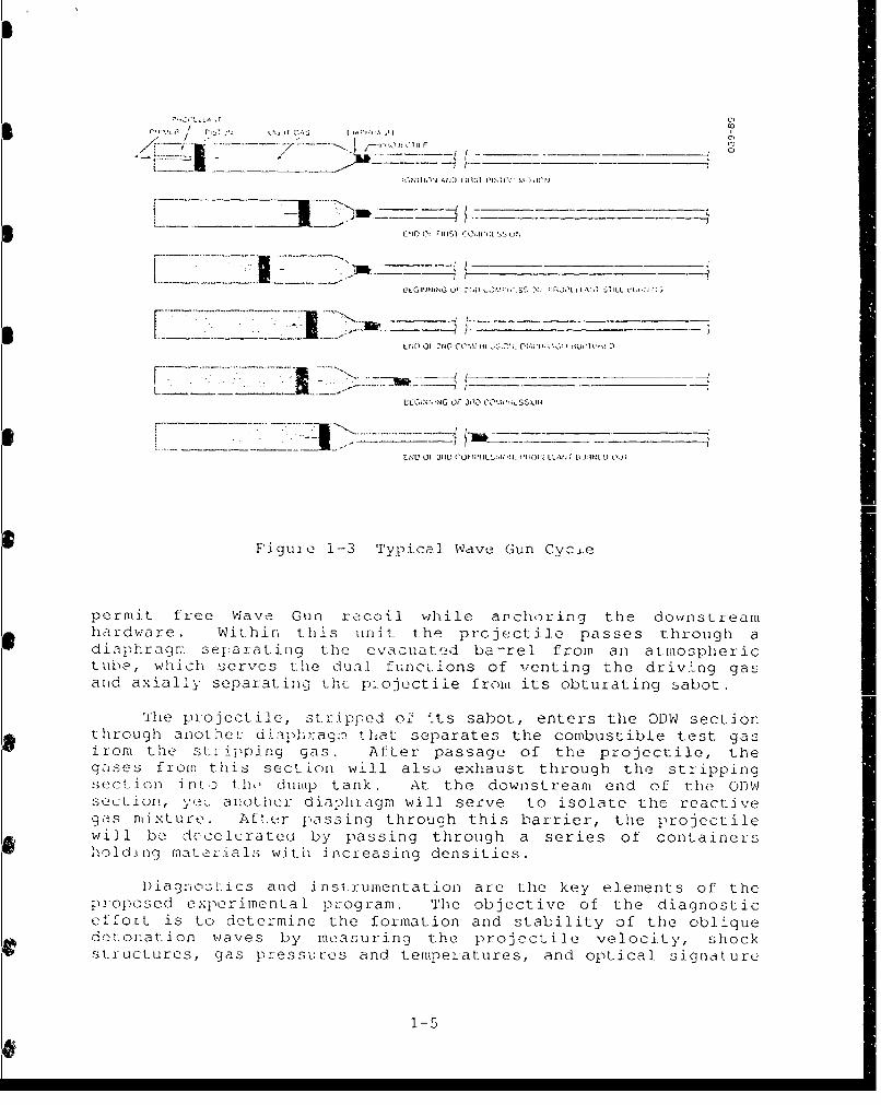
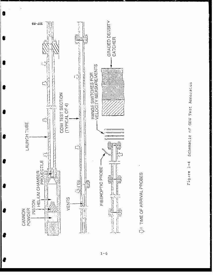
Schematic of the experimental facility for the proposedexperiment is given in Figure 1-4 . The first. element. of thesystem is a Wave Gun. The 30--mm gun constructed for theDARPA/ARDC p1 ogr-•m will be used as pieseit] y configured (1.11].Tihk: muzzle of the Wave Gun will extend into a unitV. that will
1-4
F'Cq. ,L .L A / l"T 0, m)l ' lX,(.•..
L.E _ -- • --ifl... ItNlIl A--I-'__________
_ _ : <:: ---......... ...
1 1 -T
[XX I I1,j rvlo IC, N
OLGN• i O f 2r-D -'O MI' W 55:H' ý ýqýI'ILIN `Q 11 I.:R A )L•
LLUNNING Oi- 3,10 ILS:I
F7gu11 1-3 Typical Wave Gun Cvcle
permit free Wave Gun recoil while anchoring the downstreamhardware. Within this unat the projectile passes through adiaphragm separating the evacuated ba-rel from an atmospherictube, which serves the dualt functions of venting the driving gasand axially separating the pl.ojectiie from its obturating sabot.
The projectile, stripped of 'tts sabot, enters the ODW sectionthrough another: diaphragm.- that separates the combustible test gasirom the stripping gas. After passage of the projectile, thegases froom this sect ion will also exhaust through the strippingsect ; n n o _h dump tank. At the downstream end of the ODVJsection, yet anothe r diaali..,gm will serve to isolate the reactivegas mixtur•e. Aft.er passing through this barrier, the projectilewill be deceleraten by passing through a series of containershold.Lng materials wit-h increasing densities.
Diagnosu.ics and instrumentation are the key elements of theproposed experimental program. The objective of the diagnosticeffort is to determine the formation and stability of the obliqueaetonation waves by measuring the projectile velocity, shockstructures, gas pressures and temperatures, and optical signature
1-5
Ti- >u
E") LCZI
L cuo
UN Io i
* AUw) 4)C
c<W
U) Lt-U G 1
-70
LLUJ
D1 C)l I __(44
H fl 0 £.___
*M
F 1 LLI
OC)LL LU ý
cc co L
/ / Th 20< __ CL~ Cc •ý______ 'I CL
_________________L.L.
a-__ -) clI
LjI~iJ >'~ i wLi~ -E210
Z 26

of cheoical species cieated by reactions. The diagnostic methodst.o be enopioyed for the proposed experiments mnc]tide gas pressuremCasu r-ement s, spoctral 1y iesolved opti cal measuremient s, shockstLiucturo visualizatioii anid flash x-radiographry.
This repor, t summarizes the results of the Phase 3 effortconducted in the period of 6 months from August 1988 to January19839. The pu.,pose of the Phase 1 program was to conduct basicstudies of the pronosed concept to assess its feasibility. Theobjectives of the Phas3e 1. program were to:
1. Conduct theI modynaili c/computa,-i ona I •n•id dynamic analysesof 1he ODW for a hypervelocity projectile in a combustiontube.
2. Def i ne optimum operating conditions for the proposedexpeeriment.
3. Select and establish diagnostic methods and instrumentation.
4. Design and analyze key components.
5. Pormuolate experimental proccdur•e
6. Evaluate effectiveness of the proposed experiment.
This rekpoit consists of eight sections. !n Sect-ion 2, resultsof the analyses of the hypervelocity projectile are given. Thissection includes the discussion of the ODW and analyses of thebasic thermodynamic and fluid dynamic phenomena associated withthie hypervclocity projectile in the combustion tube. A discussionof the design of hypervelocity projecti es, including stressanalysis, heat load analysis, material salection, and fabrication* method, is given in Section 3. CFD analyses of the ODW arepresented in Section 4. This section includes discussion of thecode used for the analyses of the flowfield around thehypervelocity project ile, the ODW, an)d the shock-inducedcombustion phenomena. In Section 5, a discussion of the testfacility design, functions of each component, and desionparameters is given. A summary of the work on the diagnosticmethods and instrumentat ion is given in Section G. Detaileddiscussions on each diagnostic method pert inent to t1he pioposodexperiment, includ ng instrumentation and methods ofimplementation, are given in t his section. The c.xpei i menta Iprocedure and test simulati on are discussed in Section 7 . Thepurpose of the discussion presented in this section is to si'rpulatethe actual experimental conditions so that we can have a re .istic
awareness of what is to he done in t he proposed e:-:peri merit , inthe final sect ion, Section 8, we surrun. 1 ze the resuIts nht a i ned intthis study and prescnt our assessment of the effectiveness of theproposed experiment.
1-7

[V.] O'Brien, C.J., and Kobayashi, "Advanced Earth-to-OrbitP1-roI, u s on Concepts," AlAA/SAE/ASME/ASEE 23rd JointlPropulsioen Conference, AIAA-86-1386, Huntsville, AL, June1986.
[ .2] Ostrander, M.J., J.C. Hyde, M.F. Young, R.D. Kissinger, andP.T. Pratt, "Standing Oblique Detonation Wave EngineI'erformance," 23rd AIAA/ASME/SAE/ASEE Joint PropulsionCoirference, San Diego, CA, 29 June -- 2 July 1987.
[1.31 Aiarson, T.C., and R.B. Morrison, "On The Classification ofNormal Detonation Waves," Jet- ProDuljsion, August: 1955.
I. 4] 11 r, if.F., " :-:iperiwrents on Shock-Induced Combustion,"AstrcQ;autica AcLa, Vol. 17, Nos. 4 and 5, 1972.
1 . 1] lierLt berq, T., A. P. Bi ickner, and D.W. Bogdanoff, "The RamAccelerator: A New Cf.mnical Melhod of Achieving UltrahighVe-locities," 37th Meeting of the Aeroballistic RangeAssociation, Quebec, Canada, 9-12 September 1986.
[] (-1 Gross: R .A. and W. Chinit zr "A St udv of SupcrsoniCombustion," 12_ogi Aerospace .cier__c_, July 1960.
[1.71 P Datt, I.T., J.W. Humphrey, and DI,. Ko?:s, "Morphology of aStanding Oblique Detonation Wave," 23rd AIAA/ASME/SAE/ASEEJoint Propulsion Conference, San Dieco, CA, 29 June - 2July 1987.
[1 .1 Pratt, L).T.1, and D.E. Glenn, "Numerical Simulation of aStanding Oblique Hydrogen-Air Detonation Wave," SIAMConfcrerce on Numerical Combustion, San Francisco, CA, 9-11M..ch 1987.
1 9] Bruckner, A.P., and A. llertzberg, "Development of the RamAccele atoLr Hyper vclocity Launcher," 38Lh Meeting of theAeroballi]stic Range As:sociation, Tokyo, Japan, October 6-9,1987.
[1.10] Bruckner, A. , "Laboratory Scalee 1am AcceleratorE.:re ".1nents" presented at 1988 Aerospace Engineering
Coifei.ence and Show, Los Angeles, CA, 14-16 February 1989.
[. ] 'a.m, TI'. J . , and b.S. P, andal 1, "The Wave Gun Concept for a!ly' velocity R-a.apid-lFire Weapon," presented at. the 1984JAN.A.' Propulsion Meeting, New Orleans, LA, 8 .ebr. uary1984.
1-8

SECTION 2 - ANALYSIS OF HYPERVELOCITY PROJECTILE TEST FLIGHT
In this section a description is giver, of the flowfieldsur-rounding the projectile in the tube followed by a theoreticaloverview of the oblique detonation phenomena. Finally, results ofparamretric studies pertaining to projectile design, working fluid,boundary layer, and heat transfer are presented.
2.1 FLOWEIELD SURROUNDING THE PROJECTILE
As discussed in Section 1, the projectile will be launchedinto the combustion tube filled with a fuel and oxidizer mixtureby the Wave Gun at approximately Mach 6. A conical bow shock willbe formed on the nose of the projectile as shown in Figure 1-2.The pressure and temperature will increase in the fluid as itpasses through the bow shock. The conical bow shock will reflectoff the tube wall and form on oblique detonation wave, whichsubstantially increases the temperature and pressure of the fluid.Tne flow will then proceed past the projectile to the nozzle. Thefluid will expand through the nozzle to propel and accelerate theprojectile down the tube.
2.2 THEORETICAL OVERVIEW
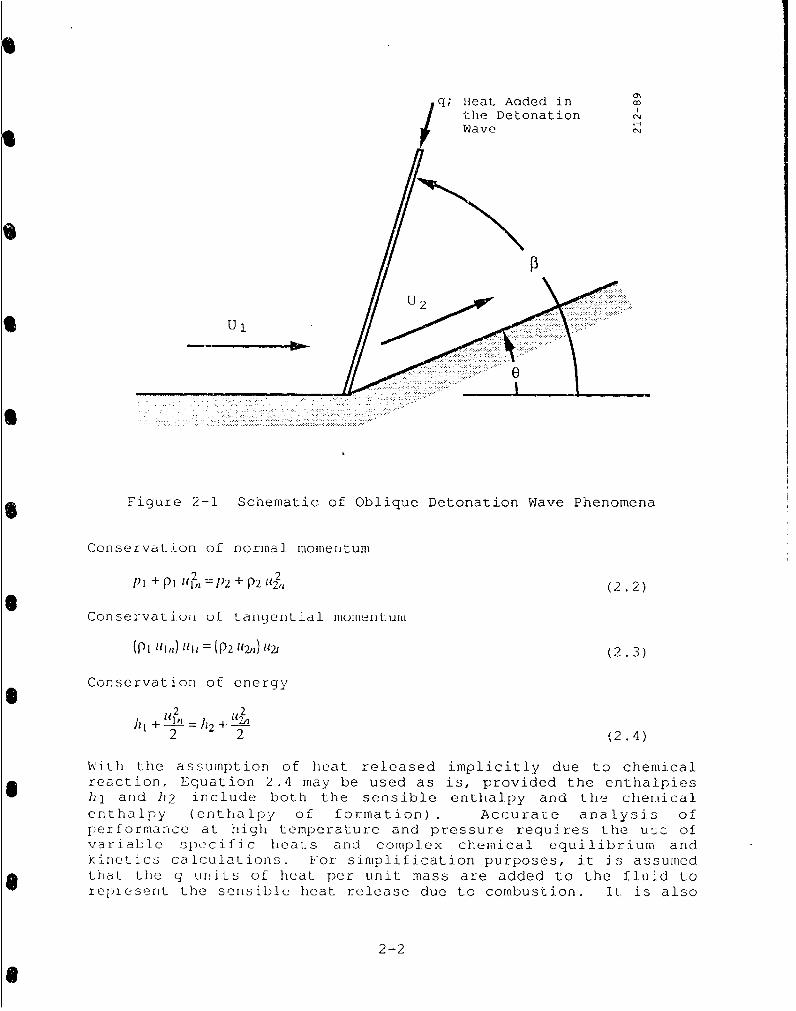
The oblique detonation wave phenomena Is described in detailby Pratt, Humphrey, and Glenn [2.1, 2.2]. Figure 2-1 shows aschematic of an oblique detonation wave. The supersonic flow isturned through an angle 0 and an oblique detonation wave is formed
at the angle 3. The addition of heat in the oblique detonationwave is what differentiates the oblique detonation wave from anob lique shock wave. Detonation occurs when a shock-inducedcombustion wave follows so closely on the igniting shock wave thatthe two waves are fully pressure-coupled. By contrast, a shock-induced combustion wave results whenever the igniting shock waveis uncoupled followed by a distinct, temporally or spatiallySesolvab]e combustion wave. More detailed discussion on thismatter is given elsewhere [2.2]. Detonation waves are classifiedas overdri ven, Chapnian-Jouguet, or underdriven, depending onwhether the normal component of the flow velocity following thewave is subsonic, sonic, or supersonic respectively.
The governing eqt'ations pertinent to the oblique detonationwave are
Conservation of mass
P[1 U1 n: )2 112n (2.1)
2-1
q; Ileat Aaded inthe DetonationWave
• ~ ~~~~~.... •::ii:i!i ......
•~~~.. ........:5:"
*~U'
- .- ..7 :.. ... ...
Figure 2-1 Schematic of Oblique Detonation Wave Phenomena
Conservation of normal momentum
PI + P P I 2,1 = 12 + P2 12,, (2.2)
Conservatiuon of tanLgential momentum
(PI "I,,) 11i = (P2 12 ) 11)21 (2.3)
Conservation of energy
2 2 1(2.4)
With the assumption of heat released implicitly due to chemicalreaction, Equation 2.4 may be used as is, provided the enthalpieshl and 112 include both the sensible enthalpy and the chemicalenthalpy (cnthalpy of formation). Accurate analysis ofperformance at high temperature and pressure requires the utz. ofvariable specific heats and complex chemical equilibrium andkinetics calculations. For simplification purposes, it is assumedthat tLhe q units of heaL per unit mass are added to the fluid torepresent the sensible heat release due to combustion. it is also
2-2

assumed that the fluid has a constant specific heat capacity anddoes not change composition when the heat is added. This resultsin the modification of Equation 2.4 to
2 2 (2.5)
The Mach number is defined as
M={Y4R (2.6)
Combination of the conservation equations (Equations 2,1 to 2.3and 2.5), the definition of the Mach number, and the descriptionof the geometry from Figure 2-1 result in
2 (2.7)
whe re
q i aPl j 2 tan( - 0)and P2 Uln tanp (2.8)
A ploL uL tihu 5ulutiuul uf E4udL Jutu 2.7 fur several values of q andconstant MI is shown in Figure 2-2. The figure shows theclassifications of the different flowfields predicted in thesolution. The first classification is that of strong and weakshocks. The solution of Equation 2.7 gives two values of P for
each value of 6. The smaller value corresponds to the weak shockand the larger to the strong shock. For all solutions where -q > 0,the minimum value of P corresponds to the Chapman-Jouguetdetonation wave with M2n = 1. Points on the constant F1 lines totne left of the Chapman-Jouguet point on the lower branch of thesolution are underdriven waves with M2n > I. Points on theconstant q lines to the right of the Chapman-Jouguet point on thelower branch and all of the points on the upper branch of thesolution have M2n < 1 and are thus overdriven. Points on thelower, weak-wave branch will be referred to as weak overdriven,and on the upper branch, as strong overdriven. However, since allstrong oblique shock waves are overdriven, they will be calledsimply strong oblique detonation waves to avoid redundancy.
Weak underdriven oblique detonation waves will not occur innature because the detonation wave cannot be maintained at theshock if the normal. component of the flow velocity following thewave is supersonic [2.2] . Weak overdriven and Chapman-Jouguetoblique detonation waves can occur in nature and are the desiredoperating condition for the oblique detonation wave experiment.
2-3

90
80 StrongShock
70- DO
60
50 WeakShock
40
*30 -UD: Underdriven;M 2 n > 1q=0 GD: Overdriven; M2 n < 1
810 Locus of Chapman-Jouquet states; M2 1
0 10 20) 30405
Figure 2-2 Variation of Oblique Shock wave Angle (P3) withTurning Angle (0) for Variable Specific hjeaLS Addition and Constant Freestreamn Mach Number andTe~mp erat u te
2-4

Just as with strong oblique shocks, strong oblique de,_,nationwaves will not occur unless there is a strong back rz..ssuredownstream. If the turning angle is too great, the o. liquedetonation wave will detach. Figure 2-2 shows that as the energyrelease is increased the maximum turning angle decreases. It alsoshows that as more energy is released, the Chapman-Jouguet angleincreases. The operational turning angles are bounded by thedetachment angle and the Chapman-Jouguet angle. As the energyrtuýlease is increased, the operating range decreases. On the otherhand, as the Mach namber of the incoming flow is increased, thedetachment angle increases which increases the operating range.The minimum projectile velocity required to establish anoverdriven weak oblique detonation wave is called the takeovervelocity.
2.3 ONE-DIMENSIONAL FLOW ANALYSIS
The analysis pertaining to optimization of the projectileshape, dimension, and operating conditions were calculated by one-dimensional code ODRAM by Pratt [2.3] . The code assumes thatViiscous effects and thermal effects (other than the fuelcombustion) are small. It also assumes that all of the fuel andoxidizer will burn completely in the oblique detonation wave. Thecode can treat any combination of fuel and oxidizer correctly.Real fluid properties and equilibrium states are calculated in thecode by using a set of combustion reaction equilibrium andkinetics (CIKEK) subroutines from Pratt and Wormeck [2.4]. Thecode calculates the conditions through a conical shock wave,oblique detonation wave, and an isentropic expansion behind theprojectile. More detailed descriptions of these three processesfol low.
Flow conditions through the conical shock wave are calculatedby using a modified Taylor-Maccoil method, based on locallyconstant Cp's, and integrated from the conical shock wave to thecone surface. An option in the code allows the conditionsdirectly behind the shock, on the surface of the cone, or someaverage of the two to be used as input to the oblique detonationwave section of the code. Then flow is calculated through anoblique detonation wave for crossflow of reactants (air-fuelmixture, ideal gas, variable specific heats, and chemicalequilibrium) for prescribed fuel/air equivalence ratio. Equations2.1, 2.3, and 2.4 are solved iteratively with the assumption thatthe flow is steady and uniform with no heat transfer. Zeroprescribed equivalence ratio simply recovers weak oblique-shocksolutions without combustion. Detonation in the oblique shockwave can 1,e turned off in the code. This allows calculation ofthe conditions downstream of the oblique shock formed at the walldue to the reflected conical. bow shock. These conditions are thenused as input to a one-dimensional chemical kinetics code CREK1Dfrom Radhakrishnan and Pratt [2.5] to determine if the fuel willignite and if so, what the induction time is. If the fuel does
2-5

ignite and the distance over which the fluid trav-ls during theinduction time is short relative to the projectile length, thenthe flame front wilt travel back up to the oblique shock wave andform an oblique detonation wave. Otherwise, shock-inducedcombustion, with heat release occurring in the annulus, is treatedas Rayleigh flow, i.e., constant area flow with heat release.
The fluid is compressed in both the conical bow shock and inthe oblique detonation wave. The code calculates a projectilediameter that will allow the fluid from the oblique detonationwave to exactly fill the annulus between the projectile and thetube wall. The code then calculates the properties downstream ofthe projectile by assuming an isentropic nozzle expansion from theannular area to the tull bore area following the projectile. Thethrust is calculated by using an integral analysis of a controlvolume which extends from the front of the bow shock to thelocation where the fluid flow has fully expanded to fill the tube.This integral analysis simplifies to the following equation todetermine the thrust
Thrust pint 4p + P p A (2 . 9)
where subscripts in and exp represent fluid conditions in front ofthe conical bow shock and after the fluid has fully expanded,respectively. The velocities are relative to a frame of referenceattached to the projectile, and Abore is the cross-sectional areaof the test facility ore The balisticJ effic ienc' is th ratio
ot the increase in the projectile kinetic energy to the energyreleased through the combustion process. It is given by
Thri.st. Vprojectile
fizt,• iwad ( 2.10 )
where hreact is the heat of combustion and ftud is the massflowrate of the fluid past the projectile. Upon completion of acalculation, the code returns the projectile performanceinformatýon and the states of the fluid five regions: 1) in thefreestream, 2) directly behind the conical bow shock, 3) on theprojectile cone surface, 4) directly behind the oblique detonationwave, and 5) in the fully expanded region downstream of theprojectile. The code does not take into account all viscouslosses and assumes a uniform flow through the annulus between theprojectile and the tube wall.
2.4 PARAMETRIC CALCULATIONS TO OBTAIN OPTIMUM CONDITIONS
The one-dimensional flow code as described in Section 2.3 wasused to conduct a parametric study to determine the optimumconditions for the proposed test. The parameters varied were:gas composition, equivalence ratio, gas temperature and pressure,projectile cone half angle, and projectile injection velocity.
2-6

The results of the parametric study on the effects ofchanging the cone half angle from 150 to 22.5' for air andhydrogen are shown in Figure 2-3. The fill pressure is 10 atm andthe temperature is 300 K. The equivalence ratio and projectilevelocity were varied to determine where the flow regime for theoblique detonation wave will be weak underdriven, weak overdriven,or detached. The weak overdriven oblique detonation wave isdesired for the test because it is predicted to be stable. Theweak underdriven oblique detonation wave is not theoreticallyjossible because the normal component of the fluid velocitydownstream of the oblique detonation wave is supersonic, whichprevents the stabilization of the detonation wave. A detachedwave will not occur because, as the flow is unable to turn as muchas requited by the configuration, it will force an overdrivennormal shock to form in front of the projectile resulting innegative thrust. This parametric study shows that increasing thecone angle increases the stability of the ob-ique detonation wave.It also shows that decreasing the equivalence ratio decreases therequired projectile injection (takeover) velocity.
The next parametric investigation presented in detail showsthe relationship between the takeover velocity, equivalence ratio,and gas composition. The takeover velocity is the minimumrequired velocity for a projectile to support an obliquedetonation wave. Figure 2-4 shows that as the fraction of theinert oas is increased, the takeover velocity decreases Again.as shown in Figure 2-3, the takeover velocity aecreases as theequivalence ratio is decreased. The following conclusions can bedrawn from the parametric studies performed: the takeover velocitydecreases as the temperature is increased and as the equivalenceratio is decreased. The takeover velocity is unaffected by thegas pressure; however, the thrust and acceleration are directlyproportional to the pressure.
As a result of the parametric study, the following testconditions were selected for the proposed experiment. Table 2-1summarizes the selected test conditions while Figure 2-5 shows ascale view of the projectile in flight within the combustion tube.A gas fill temperature of 300 K was selected because the very weaktemperature dependence of the takeover velocity is less beneficialthan the added expense and difficulty that would be incurred byperforming the experiment at a lower temperature. A gas fillpressure of 10 atm was chosen because higher pressures wouldresult in additional costs for the tube to withstand the higherthan 600 atm of pressure downstream of the oblique detonationwave. The heat transfer to the projectile wall is directlyproportional to the fill pressure and higher pressures willfurther complicate the thermal protection of the projectilesurface. Parametric runs investigating different working fluidcompositions confirmed that the takeover velocity decreases whenthe fraction of nitrogen is increased or the equivalence ratio isdecreased. However, lowering the concentration of hydrogen mightinhibit the establishment and stability of detonation in the
2-7

! Oblique Detonation Wave Parametric -iuay
*Projectile Cone Half Angle = 150 Projectile Cone Half Angle = 17.50
' i i ji ll i i, s i ll
.2 0
3.. 2.0> . . . •
, . . . . .
0.5 0.6 0.7 0.8 0.9 1.0 0.5 0.6 0.7 0.8 0.9 1.0
Projectile Cone Half Angle 200 Projectile Cone Half Angle = 22.50
2.. 3.0 3.0
> >
.) 2.5 - 2.5
2.0 -2.0
. .1.5 i 'A , 1 1..51 ... [ . 1 . .L0.5 0.6 0.7 0.8 0.9 1.0 0.5 0.6 0.7 0.8 0.9 1,0
4p1H2 + 202 + 7.52N2+ Weak Underdriven0 Weak Overdriven (Possible)
DetachedFigure 2-3 Parametric Study on the equivalence ratios
and cone half angle for constant fill pressureof 10 atm and temperature of 300K.
2-8

1l 1O 11A i i -- T T T l I I I 1 1 1
00NN
Z Z C) 0 Cl)
H0)
+ + +> 1
li (i ci4
0O C C): C)--
+ ++ ý
-0) C
<~~ ~ <\\U)0
q LOI CD 0 E'C'n 'I-6
~GAOi0 A)+8 .)1
cli cli 2 90S~

Table 2-1 Selected Test Conditions
GAS MIXTURE: 12 + AIR
PRESSURE: 10 atm
TEMPERATURE: 300 K
INJECTION VELOCITY: 2500 mr/s
THRUST: 4900N
ACCELERATION: 10,000 g
TEST SECTION LENGTH: 10m
FINAL VELOCITY: 2870 m/s
0,
x Z
P = 10 atm Conical Shock tT = 300 K W ave-" ....- . .Air + 112 . .Oblique 25.8 mm/• ' /i-: Deona o • •)/• • <•i••: • .w•• ::;•;•:•.•i:•(:::• --i::•N, 25.8 m m /
Detonatio(nS. . .." '"W . :-:: ::::! :V =2.5 km/~s -1::: < ':<-... !Wave .. 2.: km/s 30 mm
--- 35.4 mm ON• 30 mm - 9.9 mm i
Figure 2-5 ScaLe View of the Projectile in Flight with theConical Bow Shock and Oblique Det, nation Wave
2-10

ob] i quo detonation wave arid dcci-ease the foc refinance. Astoichiornetric mixture of air arid hydrogen was chosen as a goodcompLomise between a lower injection velocity and pea fiormance. Acone half angle of 200 and an injection velocity of 2.5 km/s werechosen by tiad-i rg off the performance benefits of a higherinjectoioi velocity against the Wave Gun's ability to propel theprojectile and sabot at higher velocities. These test conditionswill provide 10,000 g of acceleration to a 50g projectile and a 15percent increase in the projectile velocity as it is propelledthrough a 10m-long test section.
2.5 BOUNDARY LAYER TIIICKNLSS PREDICTIONS
Calculations have been performed to estimate the boundarylayer thickness on the projectile and on the tube wall for theproposed test conditions. The purpose of the calculat ion was toestimate the boundary layer thicknesses to determine what fractionof the annulus between the projectile and the tube wall will befilled by the boundary layer. For this analysis, the flow wasassumed to have constant properties and a constant freestreamvelocity near the wall. The constant property flow assumption isnot true, but it should lead to a reasonable approximation of theboundary layer thickness. The constant velocity assumption forflow over project.ile conical forebody at first hand appears to be.n novrw-. l i fi cat inn of ihp )trtn ] flnwfinl. 1iilt it istheoretically correct because the similarity solution ±or ilowover a cone yields a constant velocity on the cone surface.
To derive theoretical relations for the boundary layer growthon the conical forebody and the projectile body surface, thedevelopment in Kays and Crawford [2.6] is followed. A turbu].entvel.ocity profile of
r =8.750+1 { .7I= 2.11)
isý assumed fo the flow. An integral boundary, !ayr technique is
used to obtain
6 -0.036v 0.2 i /11,6I 0.8~%
R R
(2.12)
which describes the momentum thickness as a function of the fluidpropert ies arid R, the radius of the surface along the flowdirection. This is integrated to give
A= (.018 t (2.13)
where x is distance from the nose of the cone along thecenterline. The displacement and boundary layer thicknesses aierelated to the momentum thickness by
2-11

61 1.29 62 and =10.3 62 (2.14)
It is likely that in the real flowfield there will be a separatedlegion where the oblique detonation wave neets the projectilesurface. it is assumed in this approximation that this will notsubstant jiaily change the boundary layeL thickness downstream ofthis separated region. In this approximate analysis, the boundarylayer is compressed by the oblique detonation wave by the relation
P112 1ki1 = P162I ,L
ODW O0W (2.15)
The flow on the body of the projectile is assumed to be steady anduniform which results in
6, = 0.036 x (2.16)
after integrating Equation 2.12 for constant R and uoo. A relativeorigin is deteimined for Equation 2.16 by taking 82 from Equation2. !5 and solving Equation 2.16 for x. The relative origin isnecessary because the boundary layer is not zero at the beginningof the body, but has already been established. The mnomentumthickness at the end of the projectile body is determined byadding the distance to the relative origin to the length of thel•uj and usingu' .. LI. I'o0. A iii E.uaLu ui, i 2 .16.
The boundary layer profile on the tube wall is apprc.ximatedby
-/-282 = 0.037.1 1 (i - ~ I23 + ( 7t5 x l UV! I V 11UW (2.17)
which is from Derbidge and Dahrm [2.7]. In this relation, uf andUw are the fluid and wall velocities relative to the projectile.For a worst-case condition, the wall temperature can be taken tobe the same as the iceestream temperature. With this boundarycondition, Dahm et al. [2.81 gives
81 = 1.44 52 5 = 10.462 (2.18)
for the displacement and momentum thicknesses respectively foiEquation 2.17. The viscosity of a gas is a weak function ofpressure and increases with temperature. An empirical relatiunfor the viscosity of air is given by
, 7" \O.'659
p 29.6x10 " . Pas (2.19)583K1 (583 Ký(2.19)
from Anderson and Claik [2.9]. The viscosity of air is used sinceit is a good estimate of the viscosity for the mixture of air and
2-12
hydrogen upstream of the oblique detonation wave and for themixture of nitrogen and water vapor downstream of the obliquedetonation wave.
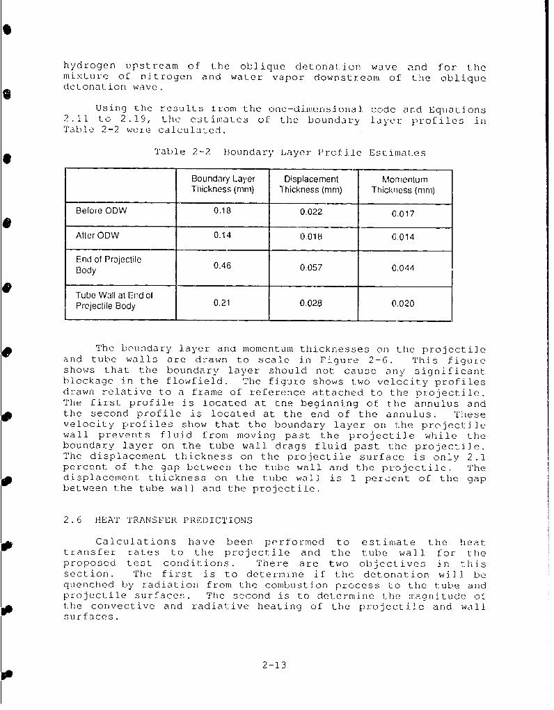
Using the results irom the one-dimensional code and Equations2.11 to 2.19, the estimates of the boundary layer profiles inTable 2-2 were calculated.
Table 2-2 Boundary Layer Profile Estimates
Boundary Layer Displacement Momentum
Tnickness (mm) Thickness (mm) Thickness (mm)
Before ODW 0.18 0.022 0.017
After ODW 0.14 0.018 0.014
End of Projectile 0.46 0.057 0.044Body
Tube Wall at End ofProjectile Body 0.21 0.028 0.020
The boundary layer ana momentum thicknesses on the projectileand tube walls are drawn to scale in FiguL-e 2-6. This figureshows that the boundary layer should not. cause any significantblockage in the flowfield. The figure shows two velocity profilesdrawn relative to a frame of reference attached to the projectile.The first profile is located at tne beginning of the annulus andthe second profile is located at the end of the annulus. Thesevelocity profiles show that the boundary layer on the projectilewall prevents fluid from moving past the projectile while theboundary layer on the tube wall drags fluid past the projectile.The displacement thickness on the projectile surface is only 2.1percent of the gap between the tube wall and the projectile. Thedisplacement thickness on the tube wall is 1 percent of the gapbetween the tube wall and the projectile.
2.6 HEAT TRANSFER PREDICTIONS
Calculations have been performed to estimate the heattransfer rates to the projectile and the tube wall for theproposed test conditions. There are two objectives in thissection. The first is to determine if the detonation will bequenched by radiation from the combustion process to the tube andprojectile surfaces. The second is to determine the magnitude ofthe convective and radiative heating of the projectile and wallsurfaces.
2-13

C1
ShoCk Oelique2AmWave De lorallon
......
.......
... . .. ...
Boundary Layer Thickness
11cal2.1 mm
'A/A- 'O . .ccuc.
Displactem nThc es
Figure 2-6 Scaled Drawing of Boundary Layer and DisplacementThicknesses on the Projectile
2-). 4

The energy released by burning the fuel in the obliquedetonation wave is
Qcomb = hreact 1h (2.20)The radiation heat flux is given by
Qwhr teA(Td -Tc4) (2.211)
where aY = 5.67x10- 8 W/(m 2 K4 ), Tf is the fluid temperature, and Twis the wall temperature. The convective heat flux is determinedby
QConv = hconv A (Ta - Tw) (2,22)
where the adiabatic wall temperature i ; given by
T- 2Cp (2.23)
The average convective heat transfer coefficient, hconv, iscalculated from the Stanton number by
0I. hconvPUCp (2.24)
The Stanton number as given by Dahm et al. [2.8] for compressibleflow over a flat plate can be averaged by integrating from thebeginning of the boundary layer and dividing by the length toyield
S"d"= 0.037F Re -0 .2pr-0 .4 (2.25)
where F is a correction factor for the property variations throughthe boundary llaycr given by
(~~~ T -. 66F = ().53Tf + 0.197Taw + 0.45TJ) (2.26)
and
Re=P Uix
9 (2.27)
For a first estimate at calculating the heat transfer to thewall, the thermal boundary layer is assumed to start on the bodyof the projectile after the oblique detonation wave. It is alsoassumed that Equations 2.25 and 2.26 will give adequate estimatesof the Stanton number for the tube and projectile walls eventhough it was derived for momentum and thermal boundary layersthat start on the beginning of a flat plate with a 1/7 power lawvelocity profile. For the proposed test conditions, these
2-15
equations give a heat transfer coefficient of 279 kW/m 2 K on the933 K projectile body. This yields a heat flux of 864 MW/m 2 or a
- total of 2.1 MW for the total surface area of the projectile body.They also give a heat transfer coefficient of 209 kW/m 2 K on the300 K tube wall. This yields a heat flux of 691 MW/rm2 or a totalof 2.0 MW for the total surface area of the tube above theprojectile body.
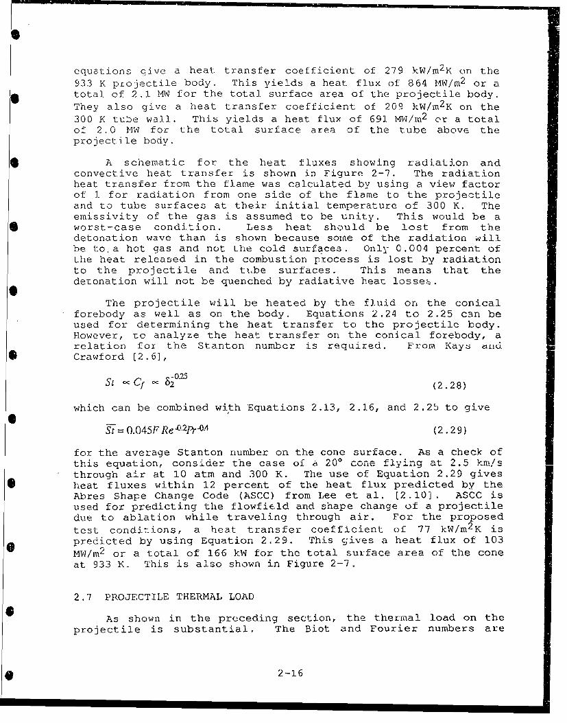
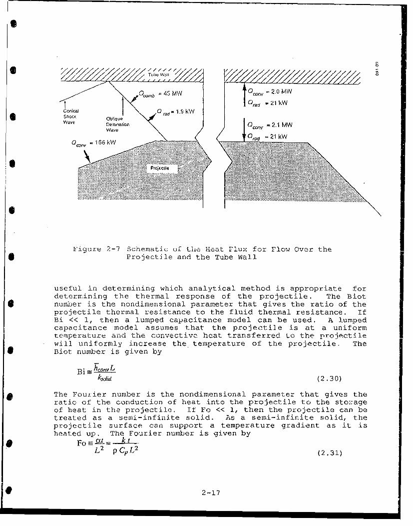
* A schematic for the heat fluxes showing radiation andconvective heat transfer is shown in Figure 2-7. The radiationheat transfer from the flame was calculated by using a view factorof 1 for radiation from one side of the flame to the projectileand to tube surfaces at their initial temperature of 300 K. Theemissivity of the gas is assumed to be unity. This would be a
* worst-case condition. Less heat should be lost from thedetonation wave than is shown because some of the radiation willbe to. a hot gas and not the cold surfaces. Only 0.004 percent ofthe heat released in the combustion process is lost by radiationto the projectile and tube surfaces. This means that thedetonation will not be quenched by radiative heat losses.
The projectile will be heated by the fluid on the conicalforebody as well as on the body. Equations 2.24 to 2.25 can beused for determining the heat transfer to the projectile body.However, to analyze the heat transfer on the conical forebody, arelation for the Stanton number is required. From Kdy. dud
*Crawford [2.6],
S 0'Cf 80(2.28)
which can be combined with Equations 2.13, 2.16, and 2.25 to giveS/
ST = 0.045F Re. 2pr--0-4 (2.29)
for the average Stanton number on the cone surface. As a check ofthis equation, consider the case of a 200 cone flying at 2.5 km/sthrough air at 10 atm and 300 K. The use of Equation 2.29 givesheat fluxes within 12 percent of the heat flux predicted by theAbres Shape Change Code (ASCC) from Lee et al. 12.10] . ASCC isused for predicting the flowfield and shape change of a projectiledue to ablation while traveling through air. For the proposedtesL conditions, a heat transfer coefficient of 77 kW/m 2 K ispredicted by using Equation 2.29. This gives a heat flux of 103MW/m 2 or a total of 166 kW for the total surface area of the coneat 933 K. This is also shown in Figure 2-7.
2.7 PROJECTILE THERMAL LOAD
As shown in the preceding section, the thermal load on theprojectile is substantial. The Biot and Fourier numbers are
2-16
0
"" / TZbe // '/ K /
Qom0-1b = 45 M'N 0oZV =2.0 MW
t 0 ,yd .21lkWConical 0 tad "1.k NShock Ob'iqueWave Delonalion Oonv 2.1 MW
Wave r ,a,1 21 kW
S~, .... .roc ..l
QO•',v1 = 166 kW -
Projfetile Xi
Figure 2-7 Schematic of the Heat Flux for Flow Over the* Projectile and the Tube Wall
useful in determining which analytical method is appropriate fordetermining the thermal response of the projectile. The Biotnuiber is the nondimensional parameter that gives the ratio of theprojectile thermal resistance to the fluid thermal resistance. IfBi << 1, then a lumped capacitance model can be used. A lumpedcapacitance model assumes that the projectile is at a uniformtemperature and the convectivc hcat transferred to the projectilewill uniformly increase the temperature of the projectile. The
* Biot number is given by
B i - -c•_ _Lksdid (2.30)
9 The Fourier number is the nondimensional parameter that gives theratio of the conduction of heat into the projectile to the storageof heat in the projectile. If Fo << 1, then the projectile can betreated as a semi-infinite solid. As a semi-infinite solid, theprojectile surface can support a temperature gradient as it isheated up. The Fourier number is given by
F o a t .. k_ t
L2 PCPL 2 (2.31)
2-17

As an illustration of this analysis, assume the projectile bodywith a heat transfer coefficient of 223 W/m2 K has a surface ofunprotected aluminum. For an aluminum projectile, the Biot numberis 17.7 and the Fourier number is 0.0017. Therefore, theprojectile cannot be analyzed with a lumped capacitance method butcan be treated as a semi-infinite solid. From Kreith & Black[2.11], the temperature profile for a semi-infinite solid at aninitial temperature of To exposed to a constant ambient
temperature of Tf and an average convective-heat-transfer
coefficient of 11"w is
T(X,t) - TI erfý - [i - + frjY)1eBi+T_- To (2.32)
where
= B (2.33)
k- 2
soli (2.34)
and
-hconv xksdid (2.35)
In this solution x is the distance from the surface in the semi-infinite solid. Using a lOm-long test section, a heat transfercoefficient of 279 MW/m 2 K from Equations 2.24 and 2.25, a melttemperature of 933 K for aluminum, and an initial projectiletemperature of 300 K. a semi-infinite calculation predicts thatthe projectile will start to melt 0.53m down t.'i test section.Assuming that while traveling down the remainder of the tube allof the heating is used to heat the aluminum from its initialtemperature to its melt temperature and then transform from solidto liquid, 5.5g of the SIg projectile will melt during the test.This is not acceptable and, therefore, thermal protection must beprovided for the projectile.
For the proposed test case in Table 2-1 and in Figure 2-5 for* a surface temperature of 933 K, Equations 2.25 and 2.29 give heat
transfer coefficients of 77 kW/m 2 K and 279 kW/m 2 K for theprojectile cone and body, respectively. For all cases of interestin the test design, the Fourier number will be much less than 1.Therefore, the semi-infinite analysis will be appropriate fordetermining the temperature profile for the projectile cone andbody. The projectile tip temperature will quickly rise to thefluid total temperature it is passing through because of thehigher heating rates near the tip and the small nose radius. The
2-18

boundary layer on the cone grows as the fluid moves down the conewhich results in the largest heat transfer located at the nose ofthe *rojectile. T'he ASCC predictions for flow through air can beused to estimate the increase in the heat transfer rates at theprojectile nose due to the thinner boundary layer at the nose.The ASCC results show heat transfer rates that are 8 times as highon the tip of a cone as at the end of the cone. The ASCCcalculations also show that the heat transfer is 1.5 times as highor higher on the first 7 percent of the projectile cone. It ishere that the nose of the projectile should be required towithstand the total temperature of the fluid.
The surface temperature of the cone and body of theprojectile can be calculated by using Equation 2.32 and estimatesof the heat transfer coefficients. For the cone, the ASCC resultssuggest that a multiplier of 1.55 is appropriate for determiningthe heat transfer coefficient near the tip of the cone. This
results in a heat transfer coefficient of 120 kW/m 2 K. For theprojectile body, the heat transfer coefficient was calculated to
be 279 kW/m 2 K by using the beginning of the body as the origin ofthe thermal boundary layer. This is a conservative estimate aswas previously described, so this value will be used withoutmodification.
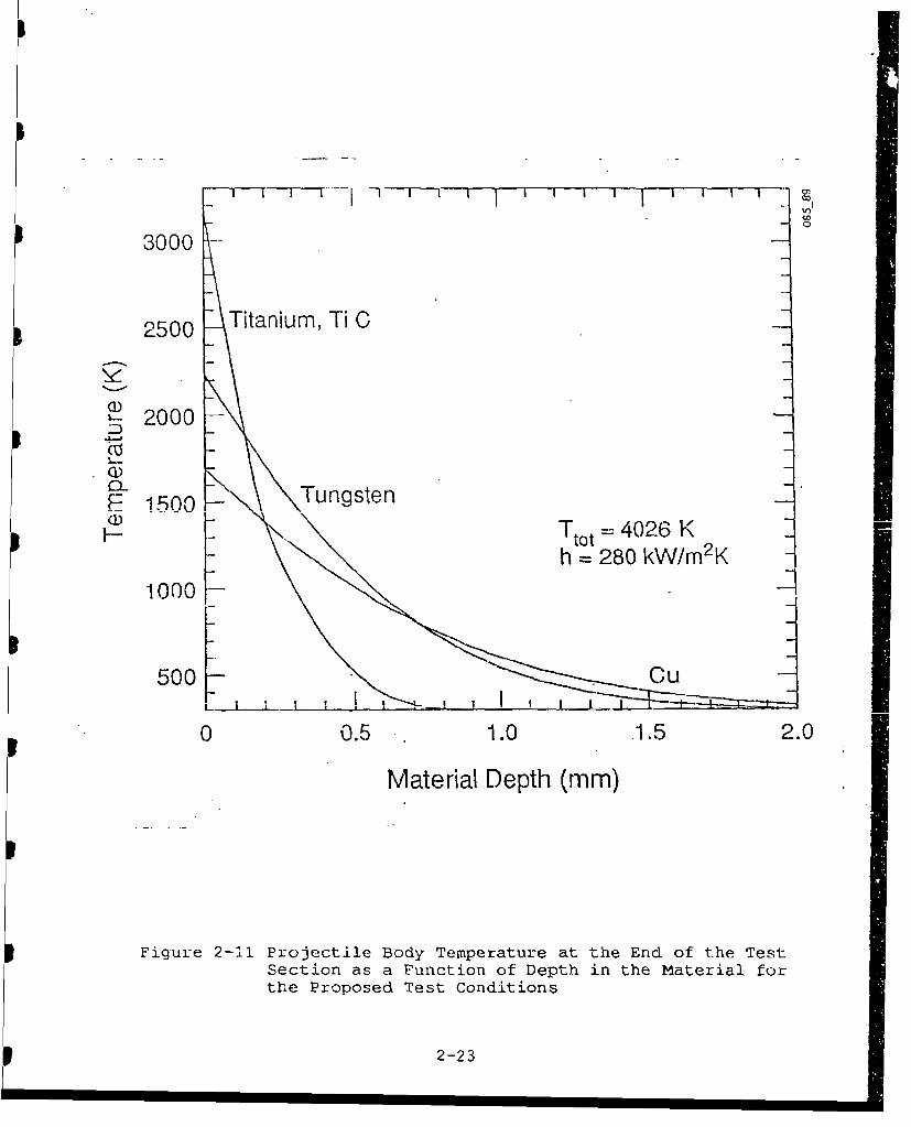
Figures 2-8 and 2-10 show tht zulface temperature of the
projectile cone and body for several materials as a function oflocation in the test section. Figures 2-9 and 2-11 show the
temperature of the cone and body for several materials as a
function of distance into the surface when the projectile reachesthe end of the test section. These temperatures were calculated
by using Equation 2.32 and a constant velocity equal to the
injection velocity of 2500 m/s to determine the time as a functionof location. These plots show the severity of the thermal
protection problem and the dependance of the surface temperatureon the material. These results will be used to select the
material for the prujeutile as discussed in Sect4on 3.
2-19
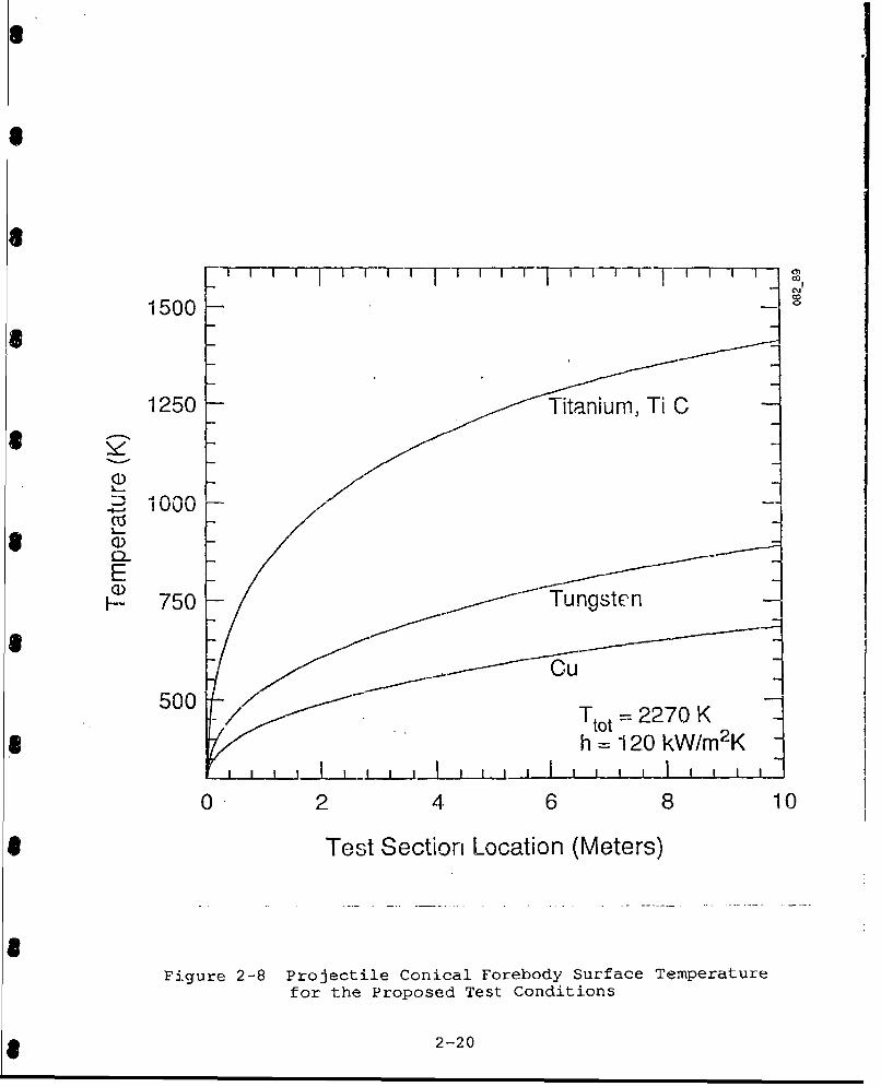
1500 F7 rT ~ n
1250 Titanium, Ti C
(15
E750 - Tungsten
500 Tt0 ~20
*h =120 kW/m2K1 I I.......I.......I.......I.......I.. I I I I I I I I I I I I I 'II0-2 4. 6 8 10
* Test Section Location (Meters)
Figure 2-8 Projectile Conical Forebody Surface Temperaturefor the Proposed Test Conditions
*~2 -20

1500Titanium, Ti C
1250
2 1000
(D0-E
ST~ 0 = 2270 K-- 750 tot
CU Tungsten h 120 kW/m 2K1-I-.- _
500
0 0.5 1.0 1.5 2.0
Material Depth (mm)
Figure 2-9 Projectile Conical Forebody Temperature at the
End of the Test Section as a Function of Depth
in the Material for the Proposed Test Conditions
2-21

3000Titanium, Ti C
2500
2000~ 2000Tungsten
*E 1500- Cu
100Ttot 4026 Kh 280 kW/m 2K
I00 2 .4 6 8 10
Test Section Location (Meter.:,)
Figure 2-10 Projectile Body Surface Temperature for theProposed Test Conditions
* 2-22
iO
I3000
2500 Titanium, Ti C
2000
_ !500 Tungsten
-- Ttot =4026 Kh= 280 kW/m2 K
1000
500 Cu -
0 0.5 1.0 .1.5 2.0
Material Depth (mm)
Figure 2-11 Projectile Body Temperature at the End of the TestSection as a Function of Depth in the Material forthe Proposed Test Conditions
2-23

Rcfcrence s(2.1] Pratt, David T., Joseph W. Humphrey, and Dennis E. Glenn,
"Morphology of Standing Oblique Detonation Waves," PaperNo. AIAA-87-1785 at the AIAA/ASME/SAE/ASEE 23ed JointPropulsion Conference, San Diego, CA, 29 June - 2 July1987.
[2.2] Pratt, David T., Joseph W. Humphrey, and Dennis E. Glenn,"Morphology of Standing Oblique Detonation Waves," toappear in the AIAA Journal of Propulsion and Power 1989.
[2.3] Pratt, David T., "ODRAM: A One-Dimensional Performance andDesign Code for ODW-Driven Ram Accelerator," personalcommunication, 1987.
[2.4] Pratt, David T., and John J. Wormeck, "CREK, A ComputerProgram for Calculation of Combustion ReacLion Equilibriumand Kinetics in Laminar or Turbulent Flow," Report WSU-ME-TEL-76-1, Thermal Energy Laboratory, Dept. of Mech.Engineering, Washington State University, March 1976.
[2.5] Radhakrishnan, Krishnan, and David T. Pratt, "FastAlgorithm for Calculating Chemical Kinetics in TurbulentReacting Flow," Combustion Science and Technology, Volume58, pages 155-176, 1988.
[2.6] Kays, William M., and Michael E. Crawford, Convective Heatand Mass Transfer, Second Edition, McGraw-Hill BookCompany, New York, 1980.
[2.7] Derbidge, T. C., and T. J. Dahm, "Recovery Tub Trade-OffStudy fo. G _LU Ld Test 1,a.,,J- R p.t- 71. ... .........TR-76-196, Acurex Corporation/Aerotherm Division, Mountain
,* View, CA 1 May 1976.
[2.8] Dahm, T. J., and L. Cooper, D. Rafinejad, S. B. Youngblood,and J. T. Kelly. "Passive Nosetip Technology (PART II)Program," Report SAMSO-TR-77-11, AcurexCorporation/Aerotherm Division, Mountain View, CA, 30November 1976.
(2.9] Anderson and Clark, "Correlation for the Viscosity of AirIncluding the Effects of Dissociation," Internal Memo,Acurex Corporation/Aerotherm Division, Mountain View, CA,1975.
[2.10] Lee, E. M., and C. L. Minell, G. L. Tice, and G. A.Wallace, "Abres Shape Change Code (ASCC 85Q) : TechnicalReport and User's Manual," Report BMO TR-86-42, AcurexCorporation, Aerotherm Division, Mountain View, CA, 7
* November 1986.
2-24

(2.11] Kreith, Frank, and William Z. Black, Basic Heat Transfer,Harper & Row, New York, 1980.
2-25

SECTION 3 - DESIGN OF iLYPERVELOCITY PROJECTILE
3.1 REQUIREMENTS FOR PROJECTILE
For a projectile to perform satisfactorily in a ramaccelerator geometry, it must survive several severeenvironments without significant deformation ordeterioration. The first of these is the stress loadingcaused by the Wave Gun injector. The acceleration processsubjects the base of the projectile to stress levels of asmuch as 500 MPa (72,500 psi) imparting accelerations of 4 x
106 m/s2 (400,000 g) or more to projectiles. The stresslevels imposed on the projectile exceed the yield strength ofmany materials, so material selection is limited to thosewith very high strength-to-mass ratios. It is necessary toconsider the stress levels throughout the projectile toensure that strengths are not exceeded at any point duringthe acceleration process. When the launch package includes asabot, the problem of avoiding excessive stresses becomeseven more complex.
As the projectile enters the ODW test section it will besubjected to conditions that are very different, but no lessextreme. As discussed in the previous section, the tip ofthe conical nose will- be immersed in stagnant Qas behind thenormal shock at that point, and refractory materials must beused there to avoid melting and the resultant ablation. Theremainder of the leading cone will be subjected to hot gasflowing across its surface behind the conical shock. It isdesirable to keep this surface and the gas in its proximitybelow the ignition temperature of the gaseous mixture toprevent premature ignition of the gas mixture in front of theprojectile. Therefore, materials with a high thermaldiffusivity are required. The "body" or cylindrical sectionof the projectile also experiences a very hostile thermalenvironment. This surface faces the detonated gas at 600 atmand 3360 K. The energy added by the detonation reaction doesincrease the temperature and pressure of the productsgreatly. Melting and the resulting ablation must still beprevented in this extremely severe atmosphere.
3.2 PROJECTILE DESIGNS
As discussed in Section 7 below, the proposed programhas two series of test activities - a preliminary test seriescalled Stage I and a subsequent main test series called StageII. The purpose of the Stage I tests is to conduct proof-of-principle testing pertaining to the validity of theprojectile thermodynamics and the effectiveness of thefacility and instrumentation. The purpose of the Stage IItests is to conduct a more detailed and indepth study
3-1
pertaining to characterization and quantification of the ODWphc nonmcna.
We will use two different projectile designs for theproposed test program: 1) a simple polycarbonate projectilefor Stage I tests; and 2) a more complex titanium alloyprojectile for Stage II tests. Specific features of eachprojectile design are discussed in the following sections.
3.2.1 Stage 1 Projectile Design
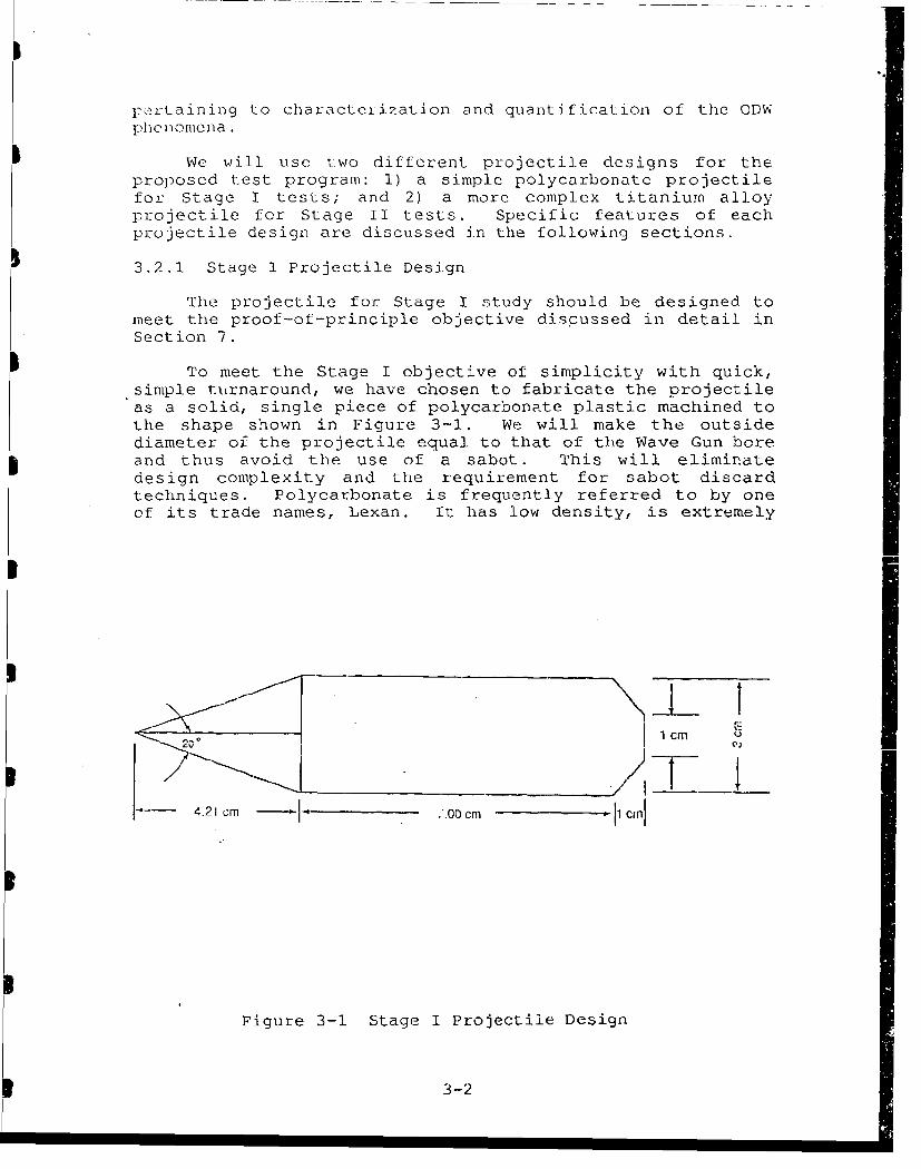
The projectile for Stage I study should be designed tomeet the proof-of--principle objective discussed in detail inSection 7.
To meet the Stage I objective of simplicity with quick,simple turnaround, we have chosen to fabricate the projectileas a solid, single piece of polycarbonate plastic machined tothe shape shown in Figure 3-1. We will make the outsidediameter of the projectile equal to that of the Wave Gun boreand thus avoid the use of a sabot. This will eliminate
design complexity and the requirement for sabot discardtechniques. Polycarbonate is frequently referred to by oneof its trade names, Lexan. It has low density, is extremely
- 4.21 cm CM c m Ci
Pigure 3-1 Stage I Projectile Design
3-2

tough in response to impulsive stresses, and has an extensive
history of success as projectile and sabot material [3.1,
3.2, and 3.3]. This choice of design and material virtually
eliminates any concern over projectile survival during the
Wave Gun launch phase. The low density of polycarbonate
(1.2 g/cm3) permits the projectile to have a long cylindrical
body without exceeding the mass that promotes in-bore
stability. Because the projectiles are solid and machined
from a single piece of rod stock, the shape can be easily and
quickly modified in response to experimental results.
The dimensions for the Stage I projectile design are
shown in Figure 3-1; they reflect the longer body possible as
a result of the lower density of the polycarbonate material.
The mass of this projectile will be 75g. This mass is well
below that which the Wave Gun can accelerate to the design
injection velocity.
3.2.2 Stage II Projectile Design
The projectile for Stage II study should be designed to
withstand extreme test conditions discussed in Section 3.2.
In contrast to the polycarbonate projectile for Stage !, the
projectile for Stage II study must complete the flight along
a 10m--long combustion tube keeping its structural integrity.
The external shape of thtý piojectile is dictated by the
nature of the ODW phenomenon as given in Figure 2-5 in the
preceding section. The design is illustrated in Figure 3-2,
together with the obturating sabot. This figure defines the
terminology to be used in the remainder of this discussion.
The centralizers mechanically hold the projectile at the
center of the combustion tube. The centralizer is designed
so as to leave a small clearance between the centralizer edge
and the tube wall. As the projectile travels along the tube,
the edge of the centralizer glides over a thin film of gas
between the centralizer edge and the tube wall, which acts as
a lubricant. The angle of the conical nose (290 hal.-..ne.
was selected on the presumption that the injection velocity
would be close to 2.5 km/s. The calculations on which this
choice is based have been discussed in Section 2. In this
si'.uation the conditions behind the bow shock should not
induce detonation, but such conditions should be achieved
upon reflection from the wall. Similar considerations
dictated the choice of body diameter. The choice of shape in
the boat-tail expansion region is somewhat arbitrary based on
the expectation that the effectiveness of this region, from
the standpoint of its function as an expansion nozzle, will
be quite high independent of details of its shape.
Centralizers are shown as an integral part of the projectile,
although the determination cf whether or not they are
required will depend on an estimate regarding the stability
of an uncentralized projectile in the geometry required for
3-3

E z
<Zm
z 0 orLup :3 J p
co 02 zE
I:F-I
LnlW
I 'I)
C~C)
<<-0
O c CC½
0 I
I- F
S 3-4

ODW demonstration. We have designed the length of the Žodyregion to be as long as mass limitations will permi todecrease the likelihood of problems resulting from a ten( 2yfor the projectile to tumble within the bore.
The bore of the Wave Gun to be used in the proposedexperiment is 30 mm. In this caliber, our experience is thatwe can accelerate an 85g launch package (including projectileand sabot) to a velocity slightly in excess of the injectionvelocity (2.5 km/s) required for ODW function. To avoid WaveGun development efforts, we have designed the launch packageto stay within that mass limit.
In the region where the very high stagnationtemperatures will be achieved, the design includes a tip ofmolybdenum alloy. The melting point of molybdenum is 2883 K,high enough to avoid melting at this critical location.Except for this region, the cone consists of a substrate oftitanium alloy clad with copper. We have chosen copper forits very high thermal diffusivity. The importance of thermaldiffusivity to this application is that it will allow thesurface to remain relatively cool and thus avoid surfaceignition as described in Section 2.7. Figure 2-8 shows theresults of a set of one-dimensional calculations thatcalculated temperature as a function of depth into semi-infinite blocks of several materials immersed in air at theconditions calculated to exist behind the conical shock wave.It can be seen that of these, only copper keeps the surfacebelow the ignition temperature for the expected duration ofthe experiment. It can also be seen that the temperature1 mm into the copper is only slightly above ambient. Forthese reasons, we have chosen to design a projectile with itsconical nose clad with 1 mm of copper despite the undesirablestructural properties of low strength and high density.
The exterior surface of the body of the projectilepresents a different thermal problem. The energy added tothe gas by the detonation process brings the temperature ofthe freestream gas around the body to more than 3000 K.Computed temperatures at the surface as a function of thedistance along the combustion tube and the temperature as afunction of depth at the end of the tube are shown forseveral. materials in Figures 2-10 and 2-11. Of these,titanium carbide was chosen because of its high meltingpoint, low density, and appropriate diffusivity. A 0.25-mm(0.01-inch) layer will be applied to the projectile body.
To keep the overall mass of the projectile below the 85glimit imposed by the characteristics of the Wave Gun, werequire a material with a low density for the major portionof the projectile. Further, in order to support thematerials described in the preceding paragraphs against thevery large forces produced at the peak acceleration of theWave Gun, we need a material with very high strength. The
3-5

family of materials for high ratios of strength to weight aretitanium and its alloys. These materials appear to be idealfor this application. We have made a preliminary choice ofan alloy designated Ti-6Al-4V (6 percent aluminum, 4 percentvanadium, and the balance titanium) for the major structuralmaterial of the projectile. With appropriate heat treatment,this material exhibits yield strengths in excess of 109 Pa(3]45 kpsi) with a specific gravity of only 4.52. Thethicknesses of the section have been chosen on the basis offabricability and on the ability to support the stressesresulting from the acceleration. We have given the conicalsection supporting the molybdenum nose tip and the coppercladding a thickness of 1.0 mm on the presumption that thisis about the thinnest section that could be reliablymachined.
The mean acceleration stresses computed along the baseof the molybdenum tip, 3 x 10⁸ Pa (44 kpsi), and at thejunction of the cone with the body, 6.54 x 10 8 Pa (95 kpsi),are well below yield strength of the titanium alloy. Thecomputed mean stresses at these and other sections are shownon Figure 3-3. It can be seen that in all cases these stresslevels are well below yield. It must be said that the abovemean stresses have been computed by dividing the total forcerequired to accelerate the mass ahead of a given section bythe area of the section. This simple methodology is adequatefor the preliminary design that is being given here. Beforethe design is experimentally applied, however, it should besubjected to a finite-element stress analysis. Such ananalysis is beyond the scope of this Phase I program.
3.3 PROJECTILE FABRICATION
The fabrication of the the projectile according to thedesign shown in Figure 3-2 will require a combination ofseveral manufacturing processes. All of these are developedconventional processes, however; no innovation or processdevelopment will be required. The nose cone is small and hassome quite thin sections, so some finesse will be requiredand no doubt some special fixtures will be needed to supportthe piece for some of the final turning operations, but suchprecision turning is routinely accomplished by quality shops.
When the form of the titanium cone is completed, thecopper cladding will be applied by electroforming to athickness in excess of the 1-mm final thickness so that thethe final shape can be produced by lathe turning. We plan toproduce the projectile body as an investment casting of thetitanium alloy with the external shape having the cruciformcross section. The casting will be made as a rod long enoughto make several projectile bodies. The internal contours
3-6

CD
CDCD -
oCL400
oxo
C))
coCr
0 CN
CD C)4-
-":r U)cas cc ) -
01- (D -L-
0CL (5 oCCD c)~ o)~-C'X XCDL
S.- LOCýT c
cc m
C)co -n o________ _ s
E--O
C~j Ir 03-7

wj il be produced by machining. The external coating oftitanium carbide will be applied by plasma spray and theexternal surfaces of the centralizers will be produced bylathe turning. The sabot can be produced by simple turningof polycarbonate rod stock.
17Ref er•~c
[3.1] Swift, H. F., and D. E, Strange, "Sabot DiscardTechnology," 38th Meeting of the Aeroballistic RangeAssociation, Tokyo, Japan, October 1987.
[3.2] Barker, L. M., T. G. Trucano, and A. R. Susoeff, "GunBarrel Gouging by.Sliding Metal Contact at Very HighVelocities," 39th Meeting of the Aeroballistic RangeAssociation, Albuquerque, NM, October 1988.
[3.3] Personal Communication with L. M. Barker, SandiaNational Laboratories, Albuquerque, NM, January 1989.
3-8

V7SECTION 4 - COMPUTATIONAL FLUID DYNAMIC (CFD) ANALYSIS OF
THE ODW STABILIZATION EXPERIMENT
4.1 INTRODUCTION
As described in Section 2, Analysis of HypervelocityProjectile Test Flight, the design of the projectile forgeneration of (and propulsion by) a weak, overdriven ODW canbe achieved by a combination of quasi-one-dimensional controlvolume analysis, finite-rate chemical kinetics, and boundary
layer wall heat flux calculations. Therefore, a major CFDeffort was not required to meet the design-of-experiment goalof Phase I.
However, the ultimate research goal is to understand thephysics of stabilized detonation waves, in order to assessthe benefits which they may offer, or the danger which theymay present, to hypersonic flight propulsion systems. Whilea "tour de force" computational modeling of the entire ramaccelerator flowfield is both challenging and interesting --and has in fact been done by Bogdanoff and Brackett [4.1], byGlenn and Pratt [4.2], and by Yungster, Eberhardt, andBruckner [4.3] -- the CFD effort must be focused on thegasdynamic and combustion processes which occur in theannulus between projectile body and launch tube wall, theregion where thc ODW is to be stabilized and investigated.,
Specifically, a key question which this research seeksto answer by diagnostic measurement, guided and interpretedby CED analysis, is under what conditions the reflectedoblique shock wave from the launch tube wall may result inone of the following phenomena:
a) No ignition within the annulus (no thrust)
b) Shock-induced combustion: the reactant mixture isignited by compression ignition, but tie induution(chemical ignition delay) time is long compared toconvective transit time through the reflected shockwave, so that the compression wave and subsequentcombustion wave are decoupled.
c) Weak, overdriven detonation, partial or complete:the induction time is comparable to or less than theconvective transit time through the reflected shock,so that some or all of the chemical heat releaseoccurs within the shock wave, thereby altering itsstructure and strength.
d) Chapman-Jouguet (C-J) detonation, partial: underconditions which would require a complete ODW to beunderdriven, and thus unstable, only partial post-induction heat release would occur, of just
4-1

sufficient heat release to permit an oblique C-Jwave to occur. As the C-J wave is only neutrallystable, possibly seve-e periodic transient waves(detonation "cells") will laterally traverse thewave front.
While the control volume analysis of Chapter 2 establishesthe necessary conditions for stabilization of an ODW,sufficient conditions for the occurrence of cases a, b, c, ord above depend on the complex, coupled interaction of time-dependent gasdynamic, chemical-kinetic, and viscous processesof the reacting gases, thus necessitating analysis by CFD.
4.2 COMPUTATIONAL APPROACH
Two parallel computational modeling strategies have beenadopted for the CFD effort. Since the planned initialexperiments have been conservatively designed to ensure thata weak overdriven, complete or near-complete ODW will result(Case c above), a computationally efficient, time-steady CFDcode with modest spatial resolution should be adequate forinterpretation and guidance of these expe-iments. For futureexperiment. s, where test conditions will be chosen to allowinvestigation of underdriven and/or C-J OnWs to Ocl-1r (c.aie dabove), a temporal- and spatial-accurate solution of thefull, transient Reynolds/Navier--Stokes equation will berequired.
4.2.1 Development of a Time-Accurate Transient CFD Code: E2D
If molecular and turbulent viscous stresses are ignored,the Reynolds/Navier-Stokes equations reduce to the Eulerequations. A two-dimensional, transient, axial symmetryEuler code E2D is being developed for investigation ofoblique C-J detonations [4.4). In its present form, E2D islimited to a nonreactinq flow. A reactive flow version ofthis code is in the development stage.
Because of the hyperbolic character of the Eulerequations for everywhere-supersonic flows, the axialcomponent of flow of information from boundaries is in onedirection only, from the inflow to the outflow boundary (that:is, the eigenva]ues of the Euler equations are all positive.)The hyperbolic character allows the flowfield to bedecomposed into streamwise zones as shown in Figure 4-1,where solutions in successive zones depend only on thesolution at the outflow boundary of the upstream zone. Sucha zonal approach has benefits beyond allowing a large problemto be divided up into more manageable smaller problems. Asis sliown in Reference [4.4], this approach allows theselective use of special solutions (analytical) for a givenzone. The result is improved co.putational efficiency andaccuracy in the solution.
4-2

(0CO
C3
S I
Figure 4-1 ITritial Solution Zones
It is reasonable to assume inviscid flow in the forebodyand annular zones since the boundary layers (both on theprojectile and on the duct wall) are estimated to bevanishingly thin, as was shown in Section 2. The expandingflow over the tail of the projectile is also well describedby the inviscid equations: since the flow is supersonic atthe outflow of the annulus, the axially increasing flow areacauses the gas to accelerate, resulting in a favorable axial
Pressure gradient. Strong viscous effects occurring afterthe recompression shock will not influence the net thrust onthe projectile, which depends only on surface pressureforces.
Further assumptions include that of ideal gas behavior,a valid assumption for the operating conditions considered.Without chemical reaction, this assumption together with thatof inviscid flow allows the use of the classical,"numerically exact" gasdynamic solution for the bow shockover a cone (Taylor--Maccoll solution) . Also, since theannular width is small relative to the projectile radius,two-dimensional planar flow in the annulus can be assumed.This additional assumption allows the use of oblique shocktheory to verify the predicted angle of the reflected bowshock, arid the Prandtl-Meyer soluLion for the expansion overthe cone-cylinder shoulder.
4-3
Hlowever, once the shoulder expansion wave interacts withthe reilected shock, a numerical solution of the governingequations is the only practical way to predict the resultingflowfield. The actual case will of course involve chemicalreaction, but by design the reaction must not occur upstreamof the first reflected shock. Thus, the solution for theforebody and shoulder expansion wave apply equally well tobotn the reacting and nonreacting cases.
For computational simplicity the special case isconsidered where the bow shock reflection is axiallycoincident with the cone-cylinder interface. The first zonecan then be treated entirely with the Taylor-Maccoll solutionfor inviscid, supersonic, axisymmetric flow over a cone, asdescribed in Section 2.
The solution in the annulus (Zone 2) requires anumerical solution of the complete Euler equations. Theaxisyrnmetric form of the equations was used even though thecylindrical effects are small in this zone. Central.differencing was used for all interior points, in combinationwith first-order TVD correction terms (4.41. Taken togetherwith first-order time differencing, the solution method isoverall of first-order accuracy. The Taylor-Maccol] solutionwas used as the inflow boundary condition and the interiorsolution was extrapolated for the supersonic outflowboundary. Reflective boundary conditions were used for bothwalls.
The Prandtl-Meyer solution was inicially used as a checkon the shoulder expansion in the annular zone. But due topoor conservation of total pressure in the first-orderapproximated strong expansion, the Prandtl-Meyer solution waseventually imposed as an additional zone in the solution, asas discussed in Section 4.3.1 below. Oblique shock equationswere used as a check on the angle of the reflected bow shock.
4.2.2 Efficient Steady-State CFD Code: RPLUS2D
An existing NASA Lewis Research Center CFD code, RPLUS2D[4.5,4.6], nas been selected as the "workhorse" for guidanceand interpretation of diagnostic experiments. The RPLUS2Dprogram is one of the RPLUS family of CFD codes developed atNASA LeRC. This code has been made available to all NASP(National Aero--Space Plane) contractors and similarpermission for its use and required modification has beengranted to the University of Washington. The RPLUS codeshave been tested on a wide variety of reacting andnonreacting flows and comparisons with experimental data haveshown good agreement [4.5,4.6].
The RPLUS2D solution algorithm is computationallyefficient. In its vectorized form, only tens of minutes arerequired to achieve converged solutions on a Cray XMP/48
-4

supercomputer. in its non-vectorized form, RPLUS2D executesin a relatively few hours on VAX class minicomputers. As inall practical implicit schemes, the equations are factored,in this case using the "LU" factorization scheme of Jamesonand Turkel [4.7]. Further simplification is achieved bytaking the limit as the timestep approaches infinity, so thatthe converged solution can be achieved by diagonalized Newtonitezation. Because of the latter feature, RPLUS2D can beused only for steady-state solutions.
RPLUS2D models all of the basic physics important to theram accelerator. It solves the two-dimensional Navier-Stokesequations for a reacting gas mixture. Closure of theReynolds stress term is accomplished with a Baldwin-Lomaxalgebraic eddy viscosity model with a constant turbulentPrandtl number of 0.9. Turbulence-chemistry interactioneffects are not accounted for. The present version isspecialized to hydrogen-air mixtures and ideal gas equationsof state, and considers a 13-reaction mechanism with 8species. However, the code is being modified to admitarbitrarily specified gaseous mixtures.
Modifications were made to the as-received code toincorporate the inflow boundary condition as described inReference [4.4]. This inflow boundary condition results froman inviscid solution and therefore does not give the properinflow conditions for the viscous simulations that will bedescribed below. This modification will be correctly treatedin future work. Also note that axisymmetric terms are notincluded in the RPLUS2D algorithm and thus the solution isfor the 2-D planar case. However, as described previously,this is a good approximation to the annular flowfield. Latersolutions for the forebody and plug nozzle flowfield willrequire that these terms be added.
4.3 COMPUTATIONAL RESULTS
Results using both codes are presented for a single testcase, that of inviscid, nonreactive flow with parametersgiven in Table 4--1. (Note that the Mach number included inTable 4-1 is not an independent parameter as it is calculatedfrom the preceding two parameters.) All results arepresented in their dimensionless form. Nondimensionalizingparameters are described in Reference [4.4]-
4-5
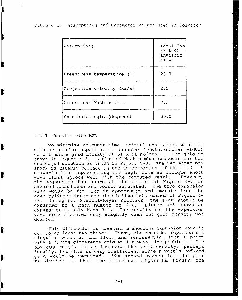
Table 4-1. Assumptions and Parameter Values Used in Solution
Assumptions Ideal Gas(k=1 .4)InviscidFlow
Freestream temperature (C) 25.0
Projectile velocity (km/s) 2.5
Freestream Mach number 7.3
Cone half angle (degrees) 20.0
4.3-! Resuilts withb R21-
To minimize computer time, initial test cases were runwith an annular aspect ratio (annular length:annular width)of 1:1 and a grid density of 61 x 51 points. The grid isshown in Figure 4-2. A plot of Mach number contours for theconverged solution is shown in Figure 4-3. The reflected bowshock is clearly defined in the upper portion of the grid. Ad.Law--iii line representing the angle from an oblique sh..ckwave chart agrees well with the computed result. However,the expansion fan shown at the bottom of Figure 4-3 is Ismeared downstream and poorly simulated. The true expansionwave would be fan-like in appearance and emanate from thecone cylinder interface (the bottom left corner of Figure 4-3). Using the Prandtl-Meyer solution, the flow should beexpanded to a Mach number of 6.4, Figure 4-3 shows anexpansion to only Mach 5.4. The results for the expansionwave were improved only slightly when the grid density wasdoubled.
This difficulty in treating a shoulder expansion wave isdue to at least two things. First, the shoulder represents asingular point in the flow, and representing such a pointwith a finite difference grid will always give problems. Theobvious remedy is to increase the grid density, perhapslocally, but this is very inefficient since a vastly refinedgrid would be required. The second reason for the poorresolution is that the numerical algorithm treats the
4-6

pS
51xS
CD
01 co
c-'
IU
1 4-7 . -

C?
f C
Lii
Cl Ii
II
~-I
tii
A -
ti/I IiLO
.1 / .- _ -° A-I
Sn i00 .0 2 5 ( 2'0o ,) ; 51 .1 0 0 0 . '12 5 Q .'1 5 .91 1
Figure 4-3 Mach Number Contours for Test Problem
4-8
,S.-- ." .. /" ._ ." . .• ._- ._ --•
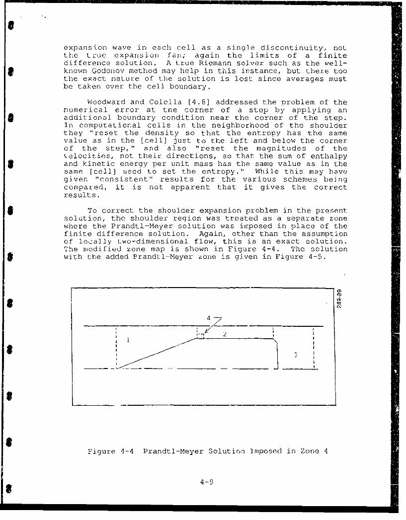
expansion wave in each cell as a single discontinuity, notthe true expansion fan; again the limits of a finitedifference solution. A true Riemann solver such as the well-
9 known Godonov method may help in this instance, but there toothe exact nature of the solution is lost since averages mustbe taken over the cell boundary.
Woodward and Colella [4.8] addressed the problem of thenumerical error at the corner of a step by applying anadditional boundary condition near the corner of the step.In computational cells in the neighborhood of the shoulderthey "reset the density so that the entropy has the samevalue as in the [cell] just to the left and below the cornerof the step," and also "reset the magnitudes of the.elocities, not their directions, so that the sum of enthalpyand kinetic energy per unit mass has the same value as in thesame [cell] used to set the entropy." While this may havegiven "consistent" results for the various schemes beingcompared, it is not apparent that it gives the correctresults.
To correct the shoulder expansion problem in the presentsolution, the shoulder region was treated as a separate zonewhere the Prandtl-Meyer solution was imposed in place of thefinite difference solution. Again, other than the assumptionof locally two-dimensional flow, this is an exact solution.The modified zone map is shown in Figure 4-4. The solutionwith the added Prandtl--Meyer zone is given in Figure 4-5.
C?2
4-
I--
Figure 4-4 Prandtl-Meyer Solution Imposed in Zone 4
1-

0)
Ln01o
__.___
LM
- ranaTI-Mever _-_ )OIUTion -one
-: -7-t -
.'I -.------ -- -- -- 7
0000 0.025 0.050 0.075 0.100 0.125 0S0 0.17S
Figure 4-5 Result with Prandtl-Meyer SolutionApplied in Shoulder Zone
4-10
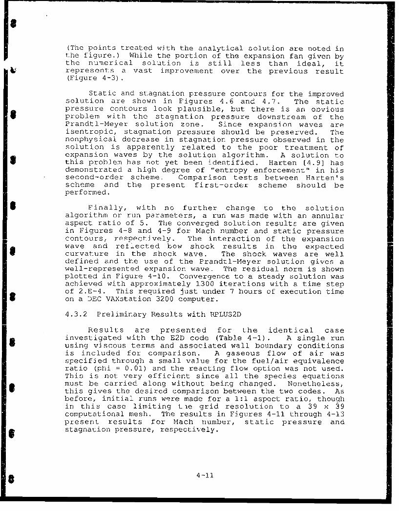
(The points treated with the analytical solution are noted inthe figure.) While the portion of the expansion fan given bythe numerical solution is still less than ideal, itrepresents a vast improvement over the previous result(Figure 4-3).
Static and stagnation pressure contours for the improvedsolution are shown in Figures 4.6 and 4.7. The staticpressure contours look plausible, but there is an obvious
S problem with the stagnation pressure downstream of thePrandtl-Meyer solution zone. Since expansion waves areisentropic, stagnation pressure should be preserved. Thenonphysical decrease in stagnation pressure observed in thesolution is apparently related to the poor treatment ofexpansion waves by the solution algorithm. A solution to
* this problem has not yet been identified. Harten [4.9] hasdemonstrated a high degree of "entropy enforcement" in hissecond-order scheme. Comparison tests between Harten'sscheme and the present first-order scheme should beperformed.
* Finally, with no further change to the solutionalgorithm or run parameters, a run was made with an annularaspect ratio of 5. The converged solution result- are givenin Figures 4-8 and 4-9 for Mach number and static pressurercontours, respectively. The interaction of the expansionwave and reflected bow shock results in the expected
S curvature in the shock wave. The shock waves are welldefined and the use of the Prandtl-Meyer solution gives awell-represented expansion wave. The residual norm is shownplotted in Figure 4-10. Convergence to a steady solution wasachieved with approximately 1300 iterations with a time stepof 2.E-4. This required just under 7 hours of execution timeon a DEC VAXstation 3200 computer.
4.3.2 Preliminary Results with RPLUS2D
Results are presented for the identical caseinvestigated with the E2D code (Table 4-1). A single runusing viscous terms and associated wall boundary conditionsis included for comparison. A gaseous flow of air wasspecified through a small value for the fuel/air equivalenceratio (phi = 0.01) and the reacting flow option was not used.This is not very efficient since all the species equationsmust be carried along without being changed. Nonetheless,this gives the desired comparison between the two codes. Asbefore, initial runs were made for a 1:1 aspect ratio, thoughin this case limiting tie grid resolution to a 39 x 39computational mesh. The results in Figures 4-11 through 4-13present results for Mach number, static pressure and
5 stagnation pressure, respectively.
* 4-11

S
'--3
Lfl
21
Zn
r,•/. " ."
.• .-
*d
.000 'n. 025 0.050 0.075 e.-00 0. 125 Q. L-•
Figure 4-6 Static Pressure Contours
4-12
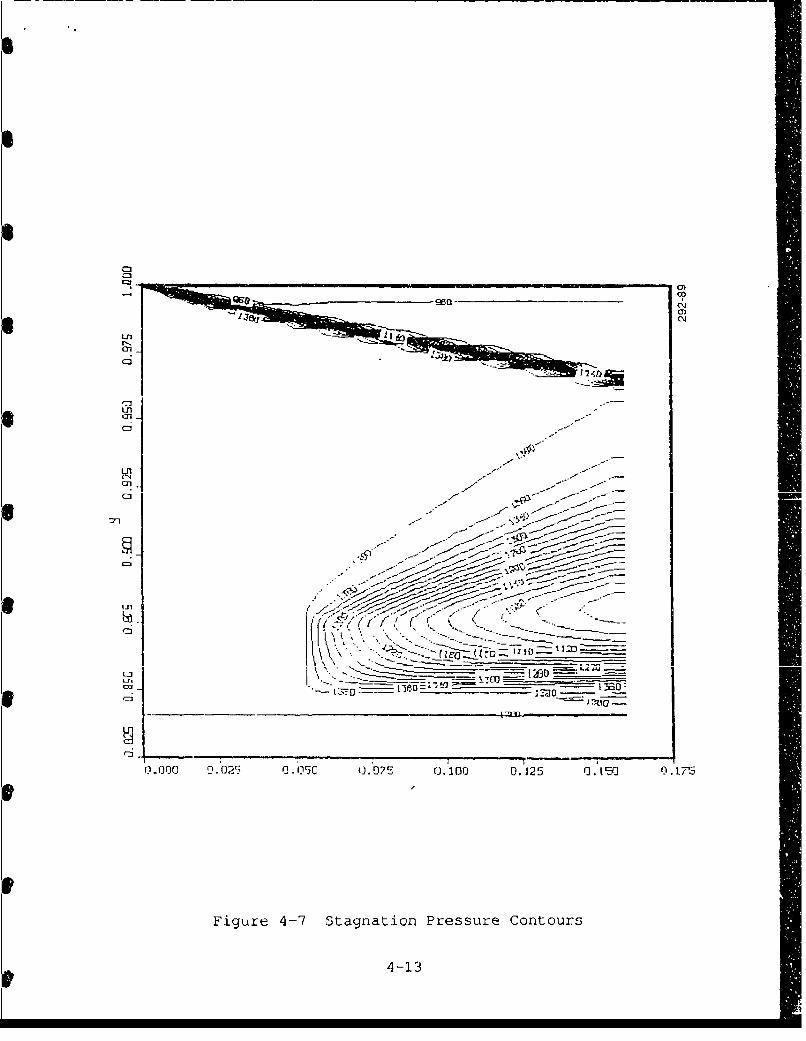
-31
CM
1-31
LflC-4C3
c-I -
Lfll rr
4-13
6 -A ~i,----.-b:
L n -' . o"
• /- .. -- . .
.•---T~ 1 _ ___.,._ ---- LE-. D:-
'XIJO ....0~ _.-5 O 0.125• 0.-1.--7•-
Fiur,-7Stga -o Pressure- Contour-s_._z--.--
4 -" - 13/--J• • -- ". . ... . .- • • ••

CO)
Eager ,- -
0.0 0 .1 0.3 0. 0.5 0.- 0.7 0.8
Figure 4-8 Mach Number Contours for 5:1 Aspect Ratio
,C?
-. .- -- ,-7y-- ,-- -/ - / ) -7o.• - .d=- • • --- •... •'-- 4- . --
- -- Z_ " 2.2 --' .. ,. -
C3 .0 0 o0.1 0 o_0 .3 . . 6.C -.. .. I-3
Figure 4-9 Static Pressure Contours for 5:1 Aspect Ratio
4-14

6g-S6S
04
r-- L0
Reflectve blc
6 0r-
/ -a
e I I I I I I I
Ionlp!SOJ ,.o u.sJou--z: 5 Ol
Figure 4-10 Convergence History, Annular Flow Field,Reflective b.c.
4-15

C3
cn
3aCl0
cn.
a,
Ci -
Uvscd RPUSD
4-16.

SC
* ci _ _ 0*Cn.,C3N
In q7
U,
(n
civscd PLSD
S4 17
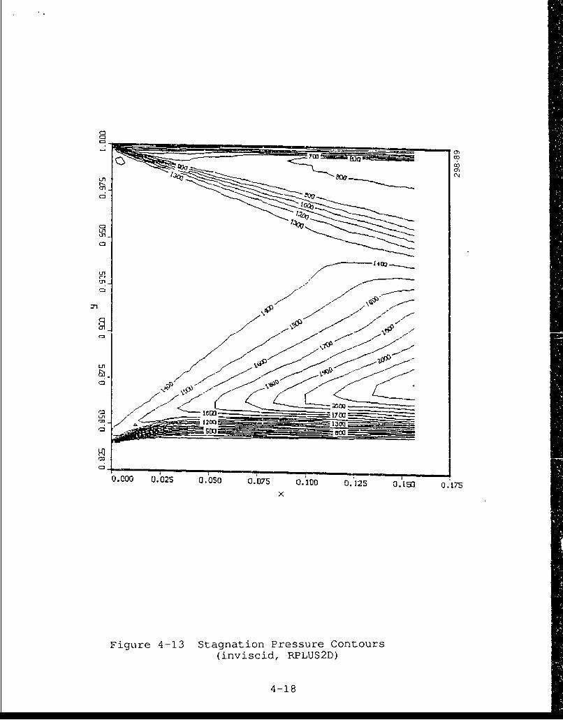
c:2
7o
0)
a,oo cz]q
-3
L--V
oooo0 0.025 a.oso 0.075 0.0 O.'125 . 5 O.uT
x
Figure 4-13 Stagnation Pressure Contours(inviscici, RPLUS2D)
4-18

S
Figure 4-11 can be compared directly with results fromE2D in Figure 4-3. Several observations can be made. First,the shock predicted by RPLUS2D is significantly more smeared,
Seven if one allows for the coarser mesh. Furthermore, theshock angle is not well predicted as is evidenced by theexact value shown in Figure 4-11 (11.350 from horizontal).Only the final contour matches this value in the RPLUS2Dsolution, whe!reas the E2D predicted shock is smeared nearlyequally to both sides of this value. The second observation
Sis the overall poor representation of the expansion fansgiven by both codes. The RPLUS2D result is, however, muchbetter in terms of the degree of expansion predicted (RPLUS2Dgiving the exact value of Mach 6.4 versus Mach 5.4 for E2D).The expansion fan problem was addressed with E2D by imposingthe analytical solution in the shoulder region. This "fix"
* has not been made in RPLUS2D. Another observation is that ofthe thick iumerical boundary layer present on both wallboundaries of the RPLUS2D solution. This behavior is presentin all of the inviscid solution results with this code and isapparently a problem with the boundary condition, as will beshown directly.
First, however, consider Figure 4-1.3 which showscontours of stagnation pressure. As in the E2D solution,stagnation pressure (thus entropy) is not preserved throughthe expansion fan. One great difference is that stagnationpressure is seen to increase in the RPLUS2D solution.
S Although neither an increase nor a decrease is acceptable,the increase does seem m-re unsettling. A decrease might beexplained through arguments of numerical dissipation, but aneasxV explanation for an increase is not immediately apparent.Magnitudes of change are significant in both cases and are ofthe same order.
Addressing the problem of the inviscid boundarycondition, the same solution was repeated for the viscouscase and results are shown in Figure 4-14. When comparedwith the inviscid case (Figure 4-11), there a differencebetween the two, albeit a very small one. Noting that theS boundary layer should be very thin since the upstreamsolution is inviscid, this is not a very conclusivecomparison. A substantial comparison is given using the testproblem provided with RPLUS2D, uniform Mach 4 flow over a 100ramp. The grid is illustrated in Figure 4-15. Mach numbercontours for the viscous and inviscid cases (both
* nonreacting) are given in Figures 4-16 and 4-17,respectively. Both walls are initially parallel to the flow.While weak shocks off the developing boundary layer areexpected in the viscous solution, there should be none in theinviscid case. Figure 4-16 shows the expected behavior forthe viscous case, but the inviscid result in Figure 4-17 isclearly incorrect. A close examination of ,he code isrequired to see why this is occurring.
4-19

C3)
0~1
C:3.--
Ln~
Ln-
7 M
Ln~
C3-
al_ _
C:)-,
000o0 0.025 a.0650 0.1075 0.30) 02I5 U. L50 0. L75x
Figure 4-14 Mach Number Contours(viscous, RPLUS2D)
4-20

C9)
Figure 4-15 Grid for RPLUS2D Test Problem(49 x 39, 10 deg. ramp)
Oz
.5A._____ _ _ _a
Figure 4-16 -Mach Nuimber Contours for Test Problem(Mach 4 inflow, viscous nonreacting)
4-21
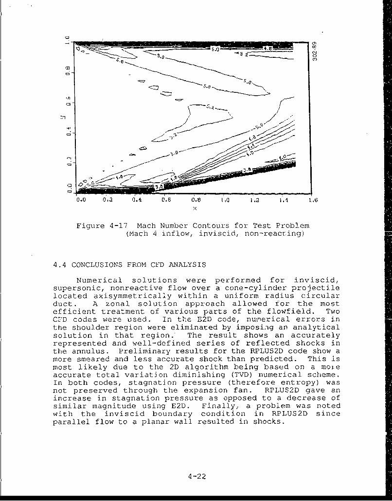
.--. _-
'J-3
-71/./
..- ,'..
,:,-
0.0 0.2 ,'i. DI.6 0.e LO 1.2 1. 4 .6
Figure 4-17 Mach Number Contours for Test Problem(Mach 4 inflow, inviscid, non-reacting)
4.4 CONCLUSIONS FROM CFD ANALYSIS
Numerical solutions were performed for inviscid,supersonic, nonreactive flow over a cone-cylinder projectilelocated axisymmetrically within a uniform radius circularduct. A zonal solution approach allowed for the mostefficient treatment of various parts of the flowfield. TwoCFD codes were used. In the E"M code, nui-erical errors inthe shoulder region were eliminated by imposing an analyticalsolution in that region. The result shows an accuratelyrepresented and well-defined series of reflected shocks inthe annulus. Preliminary results for the RPLUS2D code show amore smeared and less accurate shock than predicted. This ismost likely due to the 2D algorithm being based on a moieaccurate total variation diminishing (TVD) numerical scheme.In both codes, stagnation pressure (therefore entropy) wasnot preserved through the expansion fan. RPLUS2D gave anincrease in stagnation pressure as opposed to a decrease ofsimilar magnitude using E2D. Finally, a problem was notedwith the inviscid boundary condition in RPLUS2D sinceparallel flow to a planar wall resulted in shocks.
4-22

4 .5 PLANS PUP FUTURE WOKK
As described previously, the use of the time-steady codeRPLUS2,D is proposed for the bulk of the experimental designand analysis. The inviscid boundary condition problem mustbe resolved and a couple of modifications must be made beforethe code is put to work. These modifications include theaodditiun of axisymmetric terms and the addition ofgeneralized gaseous fuels capability.
Development of the transient code will continue for usein later investigation and analysis of ronsteady phenomena.For the non-reactive case, the first task is the search forand testing of an alternative solution algorithm to improve:he treatment of expansion waves. Harten's second orderscheme has been identified as one option. The second task isthe addition of viscous terms to investigate the influence ofboundary layers.
For the reactive case, a two-stage investigation isproposed. The first stage will follow the approach taken ina related computer simulation of a ram accelerator asdescribed in [4.2] . In that simulation, a one-parameterinduction time model due to Oran et al. [4.10] was used todetermine the onset of chemic.l heat release following theinduction or ignition delay reactions, following which thegases were assumed to instantaneous ly achieve chocmical.equilibrium- To minimize the computational burden ofcomputing the fully detailed finite-rate chemical kinetics inthe computati-,:Žal flowfield, the next stage will employ atwo-regime m" due to Korobeinikov [4.11], as recently usedin a related problem by Fujiwara [4.12].
"Ref""e 'A
[4.1] Bogdanoff, D.W., and D.C. Brackett, "A ComputationalFl~D nynamics code for the .rstination of Ramjet-in-Tube Concepts," Paper No. AIAA-87-1978,AIAA/ASME/SAE 23rd Joint Propulsion Conference, SanDiego, California, 29 June-2 July 1987.
[4.2] Glenn, D.E., and D.T. Pratt, "Numerical Modeling ofStanding Oblique Detonation Waves," Paper No. AIAA-88-0440* AIAlA 26th Aerospace Sciences Meeting, Reno,Nevada, 11-14 January 1.988.
[4.3] Yungster, S. .. S. Eberhardt, and A.P. Bruckner,"Numerical Simulation of Shock-Induced CombustionGenerated by High-Speed Projectiles in Detonable GasMixtures,' Paper No. AIAA-89-0673, AIAA 27th AerospaceSciences Meeting, ,erio, Nevada, 9-12 January 1989.
4-23
[4.4] Fort, J.A., and D.T. Pratt, "Supersonic Flow Over aCone-Cylinder Projectile Confined Within a CircularDuct, Part I - Non-Reacting Flow Over the Forebody andAnnulus," University of Washington, 10 January 1989.
[4.5] Shuen, J.S., and S. Yoon, "Numerical Study ofChemically Reacting Flow Using an LU Scheme," NASA TM180882, and AIAA-88-0436, 1988.
[4.6] Yu, S.T. et al., "Three-Dimensional Calculation ofSupersonic Reacting Flows Using an LU Scheme", PaperNo. AIAA-89-0391, 1989.
[4.7] Jameson, A. and E. Turkel, "Implicit Schemes and LUDecompositions," Math. Comp. 37, 156, pp. 385-402,October 1981.
[4.8-] Woodward, P. and P. Colella, "The Numerical Simulationof Two-Dimensional Fluid Flow with Strong Shocks,"J.Comp.Phys., vol. 54, pp. 115-173, 1984.
[4.9] Harten, A., "High Resolution Schemes for HyperbolicConservation Laws", J.Comp.Phys., vol. 49, pp. 357-393, 1-83.
[4.10] Oran, E. et al., "Numerical Simulations of Detonationsin Ilydrogen Air Mixtures," in Procccdings of theEighteenth International Symposium on Combustion,1981.
[4.11] Korobeinikov, V.P. et al., "Propagation of Blast Wavesin a Combustible Gas," Astronautica Acta, 17, pp. 529-537, 1972.
[4.12] Fujiwara, T., and Matsuo, A., "A Two-DimensionalDetonation Supported by a Blunt Body or Wedge," AIAA-88-0098.
4-24

SECTION 5 - DESIGN OF TEST FACILITY
We have designed in concept an experimental assembly thatwill allow confirmation of the establishment of a stable obliquedetonation wave (ODW). Because the experiment involves the use ofhydrogen, and because some of the processes are experimental, wehave designed the apparatus in the expectation that it will beinstalled in an outdoor, remote facility. For descriptivepurposes the apparatus may be divided into six subassemblies:
1. r he Wave Gun
8 2. The propelling gas dump section
3. The sabot strip section
4. The stripping gas and combustion products dump section
5. The oblique detonation wave section
6. The recovery section
Items 2, 3, and 4 are physically combined into a single unit,so they are discussed together. The function and some desiqnparameters of each of these assemblies are discussed in thesections that follow. Figure 5-1 shows a conceptual design of theexperimental assembly.
5.1 WAVE GUN9The Wave Gun is a variation of a two-stage light-gas gun that
has been developed by Astron as a hypervelocity launcher. Thecharacteristics of the gun are suitable for accelerating aprojectile to a velocity appropriate for study of the ODWphenomenon. The theory and some experimi.ntal results of Wave GunS development are given in Reference [5.1, 5.2]. Our description ofthe function of Wave Gun in this report will be cursory; thereader is referred to one of these references for a more completediscussion.
Figure 5-2 is an engineering assembly cf the 30-mm Wave Gun9 proposed for use in the ODW experiments. It shows in detail thecomponenL parts of this device. Near the breech end of theass2mbly is a volume known as the powder chamber. This volume isfilled with a cannon powder such as is typically used in artilleryapplications. The downstream end of this region is closed by aplastic piston that is threaded into the chamber. The pistonserves to separate the chamber from a volume of pressurized lightgas and to confine the burning powder to the chamber unti the
5-1

4-J
ci0
.lH
0
S \.\hh~':7 C)
-,--H
0f)
5-2
I • IF [ • , ! . ][ Z [ "i • - . i0

Lii
imm
FI-
I 0!2 z
uz-
ww>mIu CLUU
n-~
5-

pressure has risen sufficiently to shear the threads restrainingit. In our experiments to date, the light gas has been helium,although, for some purposes hydrogen will be more effective. Whenthe piston threads have been sheared, the piston begins to movethereby compressing the light gas and, since the piston is quitelight and moves out quickly, the pressure in the powder chamber isreduced. Ultimately, the pressure in the light gas becomes highenough to stop and reverse piston motion thereby increasingpressure and, consequently, burn velocity in the propellantpowder.
At some time in this process the pressure in the light gasbecomes high enough to break a restraint which is retaining theprojectile. The oscillatory piston moticn continues until thepowder is fully consumed and/or all of the light gas is forcedfrom the pump tube into the launch tube. For the proposedexperiment, this device will accelerate a projectile package toabout 2.5 km/s.
5.2 RECOIL ABSOvBING JOINT
The joint between the Wave Gun launch tube and the dimp andstrip tube is designed to isolate recoil of the Wave Gun from theremainder of the experimental assembly. Figure 5-3 shows aconceptual drawing of the joint. evC..l functions arc-
accomplished within this unit. First, the diaphragm thatseparates the evacuated launch tube from the atmospheric dump tubeis mounted within this unit. Second, the connection to the vacuumsystem is made in the assembly. Third, the unit is firmlyattached to the mounting beam to provide a fixed anchor for all ofthe downstream hardware, and fourth, the piece provides a meansfor maintaining an alignment between the bore of the launch tubeand the bore of the dump/strip tube uo which it abuts. The designallows a recoil cf several inches to occur before the sealing andthe alignme:nt functions are lost.
5.3 SABOT SEPARATION
Tne pro-ectile will be launched with a sabot as described inSection 3. The sabot must be separated from the projectile beforeit enteis the test. section so that the sabot will not disrupt theflowfield, in the test section. The projectile and sabot willexperience the following flight history. They will be acceleratedin the evacuated Wave Gun barrel by a helium driver gas. Theprojectile and sabot will pass through a diaphragm located at theend of the Wave Gun barrel, arid driver gas will be vented in thedriver gas venting section. The sabot will be separated from theprojectile as they pass through an axial gasdynamic sabotseparation section. The axial gasdynamic sabot separation sectiongas will be vented in the sabot separation venting section. Theprojectile will burst through a diaphragm and enter the testsection where it will be accelerated. Then it will exit the testsection through a diaphragm and be stopped in the catcher section.
5-4
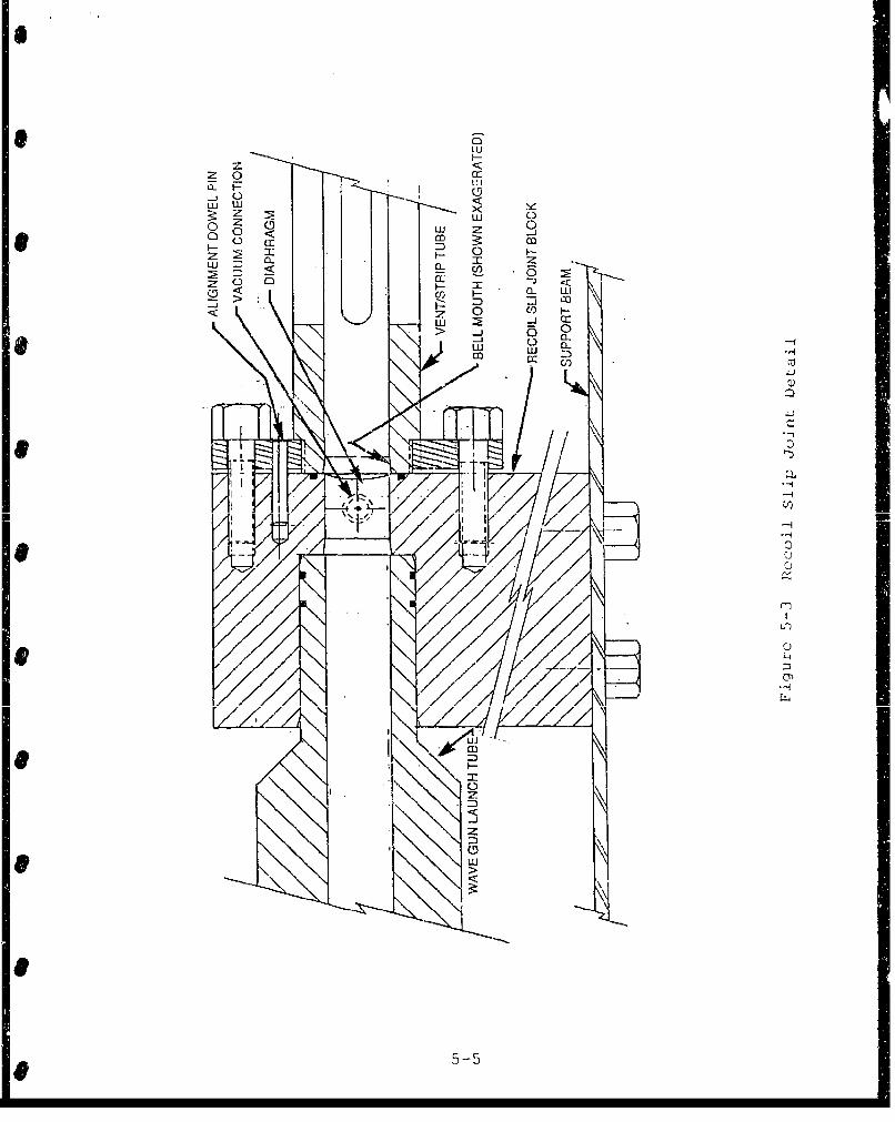
aw
zo<c
LU J ujy~z wL C~)Zi Z -
H F--~~D 2: Cl
C) TC- '20 0 : m
w~ a:
w L) Cw ::)V
Cjd)
-2
CDC
uLi
e 5-5

The helium driver gas will still be at a high pressure as itforces the projectile and sabot into the driver gas ventingsection. This high pressure must be reduced by venting for theaxial gasdynamic 2abot separator to work. The axial gasdynamicsai3t separator section consists of a straight piece of pipefilled with air at atmospheric pressure. The sabot and projectilewill force a normal shock to form in front of them as they passthrough this section. The pressure behind the shock and in frontof the projectile will be substantially higher than the pressurebehind the sabot. This compressed air will not be constrained bythe projectile so it will move past and surround the projectilewhile not slowing it. The pressure difference between the frontand rear of the sabot will slow it as it moves down the sabotstripping section. At the end of the sabot stripping section, thestripping gas will be vented. The stripping gas must be vented sothat it will not force a shock to form in the test section anddisrupt the flow.
The following sections will discuss how the helium driver gasandgadynmi saotseparat`_ýn section gas will be vented and how
the sabot will be separated from the projectile.5.3.1 Gas Venting
The gas will be vented through slots in the side of the tubew-all in the two 0.5m venting sectinns as shown in Ficure 5-4. Thevents will represent 50 percent of the surface area of the pipe inthe vent sections. A first-order analysis of the venting is madeby assuming that the gas flowing out of the vents is choked, thegas remaining in the tube expands isentropicaily, and the gasflows out the vent for a time equal to its residence time in thevent section. The integral form of the continuity equation
Ipdv + P V - A 0 •
at- f.-. J j (5.1) 1
alonc with the isentropic relations is used to derive Equation5.2, which gives the pressure in the vent section as a function oftime, geometry, and the initial conditions:
-2 -Y
pwud=phld t 4- i]711 (5.2)
where
VtrW (5.3)
For the helium driver gas venting section, Timgiw1=3(YK, Pti,' 1 = 200atnm,.5 in 00•ccand the residence time in the venting section is 20s ,
2500 n/sec
5-6

al)
Co f14
5--7
This gives a pressure of 0.36 atm behind the sabot as it enters
the sabot stripping section. A pressure of at least (±)-atrn is
required in the gas for the flow to be choked. Therefore,Equation 5.2 is not valid below this value and the pressure will
actually be somewhere between 1 atm and (YA-Iatm. For helium,
(_)--'atm equals 2.05 atm which is more than acceptable for the
entry into the sabot separator section.
5.3.2 Sabot Separation Section
The sabot will be separated from the projectile by an axialgasdynamic sabot separator. The projectile and sabot will enterthis separator at a velocity of 2.5 km/sec which gives a Machnumber of 7.2 in air at 300 K. As the projectile and sabot move
through the sabot separation section, a shock wave will precedethem as shown in Figure 5-5. This separation technique has beenanalyzed in detail by Swift and Strange (5.4]. Their paper givesthe pressure ratio across this shock as
PA,, -1 + (y + 1)M + -(y+ Y+ 2+ 16 P I--P 4 (5.4)
where M is the Mach number for the t buL ' velocity if± theundisturbed fluid before the shock. The separation between thesabot and the projectile is given to first order by
IffiýPA½JCL L22 flLý V2 (5.5)
where AP is the pressure across the sabot. AP is calculated byusing Equation 5.4 to calculate the pressure in front of the sabotand the maximum of the pressure calculated from Equation 5.2 or
-1 1
(•---•atm for the pressure behind the sabot. Equation 5.5 over-predicts the separation distance because the pressure ratio acrossthe shock decreases as the sabot travels down the tube. Equation5.4 shows that the pressure ratio across the shock decreases withdecreasing Mach number, which is the reason the p essure ratiodecreases as the projectile slows. Swift and Strange [5.4] haveperformed an iterative analysis that accounts for the changingpressure ratio. Their analysis shows that Equation 5.5 over-predicts the separation by 3 to 4 percent. Therefore Equation 5.5can be rewritten as
5X =9_6 AP Abore L2
2 M V2 (5.6)
5-8

69-L9O
EN
00
z coI
czr
0V
5w
Ct1
CDN
... .. .. ..c4-J
..0.. ..
591
The velocity of the sabot at the end of the sabot separatorsection can be approximated by
Vsao --- Vswt - .96 A b,
d nkdob V (5.7)
From Shapiro [5.3], the temperature of the gas between the shockand the sabot is given by the Rankine-Hugoniot equation as
Ti P kj, + 1 Pj
Pi4fiur 7a + 1 (5.8)
where the pressure ratio is taken from Equation 5.4. The distancebetween the shock and the sabot is given by
Pshuxk ((5,9)
where from Shapiro [5.3],
F- __ P,,1IBO " I
- I Pik• (5.10)
Using Equations 5.6 and 5.9, the conditions at the end of the 2m-
long axial gasdynamic sabot separator section can now becalculated. For a pressure of atm behind the sabot as it
exits the helium driver gas venting section and T = 300 K and P1 atm in the sabot separator section the distance between a 20gsabot and the 50g projectile will be 95 umm. The distance betweenthe shock and the sabot is calculated to be 360 mm using thevelocity at the end of the separator section as given by Equation5.7 and Equation 5.9. The temperature behind the shock will be4"150 K at the entrance and 3970 K at the exit of the sabotseparator section. Equations 5.2 to 5.3 give a pressure of 0.038atm at the end of the 0.5m-long axial sabot stripping gas ventingsection. The pressure will not drop below 1 atm but should drop
to or below (jY-1 atm which is 1. 9 atm for air.
5.3.3 Venting/Stripping Tube Construction
This component will be built using commercially availablealloy steel tubing. A likely candidate is stock tubing of 4130steel cold drawn and stress relieved with an outside diameter
5-10
(O.D.) of 60.3 mm (2.38 inches) by 28.6 mm (1.12 inch) insidediameter (I.D.) honed to the desired bore of 30.0 mm. This heavywall section is considerably stronger than required from thestandpoint of resisting the internal pressure, but we haveselected the thick wall to provide rigidity and sufficient stockfor mounting pressure gages and other diagnostic components. Asingle section of the tube will form this component. The ventingslits at each end of the tube will be made by milling slots 12 mm(0.47 inch) in diameter through the wall in four places equallyspaced around the circumference to provide venting area equal tohalf of the tube surface area. There will be two sets of theseslots at each end of the tube each about 200 mm (8 inches) longseparated by about 50 mm (2 inches) of unperforated tube. Figure5-6 illustrates the construction of this component.
5.4 OBLIQUE DETONATION WAVE TEST SECTION
The same basic tubing stock will be used for fabricating thisunit as was described for the dump/strip section, i.e., 60.3 mmO.D. by 28.6 mm I.D. honed out to 30.0 mm I.D. The full testsection will consist of four individual identical sections each2.5m long. Each section will be tapped for mounting one or morepressure transducers.
The joints between the individual sections of the testsection will utilize universal flanged connections that will alsoserve to mount diaphragms and to connect the ODW test section tothe strip/dump section. A schematic representation of one ofthese loints is shown in Figure 5-7. The method used to prepareand align the joints is a simplified version of one described bySwift and Strange [5.5). The flanges are manufactured inupstream/downstream pairs. The alignment of each pair iscontrolled by three asymmetrically placed dowel pins; theasymmetry is used to preclude misalignment by rotation about theaxis to an improper orientation. Location of the pins to ensurealignment is achieved in the following manner. The flanges arefirst threaded onto the ends of the tube section until they stopagainst a shoulder. The threads are sealed by the use of a high-strength cyanoacrylate thread-sealing cement to precludeaccidental loss of alignment. A specialized and preciselymanufactured drilling jig with a bolt circle identical to that ofthe flanges is loosely bolted to one of the flanges. The jig hasa central hole of precisely the same diameter as the bore andthree hardened precision drilling jigs representing the threedowel pin locations. The central hole and the bore are thenprecisely aligned by inserting an aligning tool consisting of ahydraulically expanded tubing into the assembly and expanding itto precisely align the two bores. The clamping bolts are thensecurely clamped and holes are drilled and reamed to accept thepins. The drilling fixture is then removed, reversed and boltedto the mating flange. The alignment process is repeated andmatching holes are drilled and reamed in the mating flange. The
5-11

KJ
0II'Cc
E m c<f 0
0 4-)
Q-)
41-
ClCtvi
Cu
nj~
I Ct1~cccii I i
5-1

ci:LuJ
LuJ2:x
r I-
-114
I---
Q))
quality and reproducibility of the alignment that can be producedby this technique is estimated to be about 25 tm. Any residualmisalignment within this range is accommodated by honing a slight"bell mouth" at the entrance of the downstream portion of eachjoint. This5 method will preclude the possibility of theprojectile encountering a step as iL proceeds across the joint.Such encounters must be strictly avoided as they will alwaysproduce a phenomenon known as "gouging" at this velocity [5.6,5.7] . Tne bell mouth technique has been shown to producesatisfactory results in our own laboratory as well as in others[5.51.
Each of the 2.5m-long units of the test section will have twoports for connecting to the gas fill system. Each of these willconsist of a pipe capped port for accepting a compression typetubing fitting and a very small (about 1 mm) hole drilled throughto the bore. This connecting hole will be oriented so as to beneither normal to the bore axis nor directed toward it to promotea helical swirl pattern as the section is filled with gas. Wehave examined the question of achieving a homogeneous gas mixturepresuming the introduction of gas at discrete locations alcng thelength of the tube. The basis for the analysis is that of binarydiffusion of gasses initially distinct and is derived from adiscussion by Bird, Stewart and Lightfoot 15.8]. They give theCI f I - -- f2-coer-ri_,_en-t- uo a t;1i- -y •a• C ., yzstte±L a ;
DI,B=0. 0018583( ' (5 . 11)
where: T is the temperature in degrees Kelvin,
IA and. M are the molecular weights of the gases,
P is the pressure in atmospheres,
a 0AB is the mean molecular diameter in angstrom ,nits,
and
Q B is an empirical constant related to the collision
frequency.
For air and hydrogen at 298K and 10 atm, the diffusion
coefficient evaluates to 0.077 cm 2/s. The time for a binary gassystem to diffuse to a given degree of uniformity is given by:
5-14

2
r. (5.12)
where. F is the residual nonuniformity (taken as 0.01 for thiscalculation),
D is the diffusion coefficient as calculated by eq.5. 11, and
L is the length of the gas column.
We guess that the characteristic unmixed length of gasesafter filling the column by the described technique will be 10 cmor less. Using this value for L w;e compute a time of about 600sec for the diffusion process to give a 99 percent uniformity tothe mix.
5.5 GAS PRESSURE INTERFACES
In Section 5.3 mention was made of pressure interfacesthrough which the projectile must pass in the course of theexperiment. In a Stage I test there is one of these interfacesb ~etweeL te veiit section and tie ODW tes.t section. Fr07 Stage ii-tests another interface will be needed between the vent/stripsection arid the evacuated Wave Gun barrel.
By far the simplest and most direct method for providingthese separations is by using a plastic diaphragm clamped in aspecial fixture such as shown in Figure 5.3. The projectilesimply pierces the diaphragm when it reaches the station. Thereis some concern that collision of the projectile with even a verythin plastic film may cause some distortion of the tip of theconical nose section. The nature of the shock structure is highlyde Plendent on the configuation of the tip, even a ninordistortion can have a profound effect on results. Fox this reasonwe have formulated a conceptual design for a fast acting valvethat will open a clear path for the projectile in an acceptablyshort. time. it is expected that the diaphragm separation willprove to be aaequate, but it is also prudent to have a backupapproach.
A conceptual design of the valve is shown in Figure 5-8. Thedriving force will be provided by a pneumatic cylinder prcchargedto a high pressure witih nitrogen. A connectir,; rod in tension isconnected to a shutter strip that passes through a slidesandwiched between the ends of the two tube sections. Gas sealing.is provided by lubricated "0" rings. The strip is restrained byan explosive bolt which, when actuated, releases the valvingstrip.
5-15

00
)< HC)-,-ccr( z U)LUQIJ~~ LULjC
0- C/)L LUj
T- 0
Cf)
04
Z -H-
nt'
_ Qa0
*: -1-
LU 0
60
5-16

A preliminary estimate indicates that a 10 cm diametercylinder charged to 2000 psi can move a slide mechanism through adistance of 9 cm in 1 msec. In this time span, a rarefaction wavewill move into the higher pressure region a distance of about 30cm. From this point on, the projectile will fly through still gasat initial conditions. Achievement of proper synchronism betweenthe actuation of the valve and the flight of the projectile willrequire caieful calibration of the function time of the variouscomponents and a sophisticated timing circuit to control theirinitiation. It is hoped and expected that zhe simapler, moredirect diaphragm separation technique will serve the requiredfunction well, but we are confident that the fast acting valve canbe successfully applied if required.
5.6 STOPPER ASSEMBLY
As its name implies, the function of this element is toprovide a means for bringing the projectile to a stop in arelatively short distance so that it can be located and examinedfor evidence as to its experience during flight. We will notattempt to make the recovery "soft" enough to permit reuse of theprojectile, but it will be very valuable if damage is sufficientlylimited to permit an estimate of whether or not surface melting orother forms of ahlat ion occ-urred dur ng the test Therequirements for this component have not been fully established atthis time, but we expect that the unit w- 11 consist of an openframework that will hold weak walls in position to containquantities of bulk material in three or four bins of increasingdensity. Such materials as sawdust, sawdust mixed with sand, andsand are under consideration as candidates. The details of thedesign of this element will be modified as a result of empiricalobservation in the course of the experimental program.
5.7 GENERAL ASSEMBLY
The unit that will provide for support and alignment of allof the elements will be a wide-flange structural beam as shown inFigure 5.1. This beam will, in turn, be supported by sections ofpipe attached to a support slab and to the beam by standardflanges. The Wave Gun is already provided with a mount designedto support the gun on a beam with a flange that is 8.5 in wide.For simplicity, a beam with this width will be used. The fulllength of the test assembly will be about 20 m. Some additicnallength of beam will be needed to accommodate recoil, recoil
absorbing apparatus, the external velocity measuring switchassembly and some room for axial movement to accommodate assemblyand disassembly. The full beam length requirement will be about25 meters or about 80 ft. The maximum length of beam that can beobtained and delivered to the test site is not known, but clearlyat least two, and more probably four, beam sections will berequired. The beam support will need to be designed so that there
5-17

is a mechanism for supporting the joints between sections andaligning them with precision both laterally and in elevation.
The tubing sections themselves will be supported on rollersand frames that are constructed entirely of commercially availableunits that are part of a modular construction system known as"Unistruit." This system offers a rich variety of components thatcan serve a selection of functions and are quite reasonablypriced. Each of the support structures will include a rollerdevice that constrains the tube to a fixed transverse position butpermits free axial motion. Such flexibility is essential topermit efficient disassembly, inspection, refurbishment andreassembly of the apparatus. The joining techniques that areinherent to the modular system permit all necessary adjustmentswithout the fabrication of any special parts. An opticalalignment telescope will he used to align each of the rollerassemblies with the range centerline.
L [5.1] Dahm, T.J. and Randall, D.S.; "The Wave Gun Concept for aHypervelocity Rapid-Fire Weapon." Presented at the 1984JANNAF Propulsion Meeting, New Orleans, LA, February 1984.
[5.2] Dahm, T.J., Randall, D.S. and Sullivan, J.D.; "Wave GCupPerformance through Evaluation and Analysis, Volume I,Summary of Program and Results." Astron Research andEngineering Report No. FR-7045-01, June 1987.
j5.3] Shapiro, Ascher H., _Le Dynalwoa. --andherxodynamic,_lFluid Flow, Volume I, The Ronald Pcess Company,
New York, 1953.
[5.4] Swift, H.F., and Strange, L.E.; "Sabot Discard P'ecbnology,"38th Meeting of tle Aeroballistic Range Association, Tokyo,Japan, October 198e.
[5.5] Swift, HF. and Strange, D.E., "Couplinq Tube Seaments forHigh-Performance Launchers, 33 35th Meeting of theAeroballistic Range Association, San Antonio, TX, Octobet:1985.
[5.63 2arker, L.M., Trucano, T.G. and Susoeff, A.R., "Gun BarrelGougin.•g by Sliding Metal Contact at VeLy High Vel.ocities."39th Meeting of the Aeroballistic fange Association,Klbuquerque, NM, October 1908.
[5.7] Personal Commpinication with L.M. Bar.xer, Sandia NationalLaboratories, Albuquerque, NM, JGnuary 1989.
[5.8] Bird, R.B., Stuart, W.F. and Lightfoot, E.N,, 2irns•tntPhermjina, John Wiley and Sons, Inc., 1960.
5-18

SECTION 6. DIAGNOSTIC METHODS AND INSTRUMENTATION
The objectives of the diagnostic effort are to identifyconfirm and analyze the formation an( stability of an obliquedetonation wave. We have designed a variety of diagnos-.ictechniques by which the success in achieving this goal can buevaluated. In this section we discuss an overview of diagnoscicmethods to be employed for specific measurements in Sectioa 6.1.More detailed discussions of each of the diagnostic technique'. aregiven in Sections 6.2, 6.3 and 6.4.
6.1 OVERVIEW OF DIAGNOSTIC METHODS
In order to obtain data for in-depth characterization of theODW phenomena the following quantities will be measured:
*Projectile vclocity
-Structure of the shock waves in the region surroundingthe projectile
-Gas pressure history at the wall of the ODW tube
•Gas temperature in the various thermody:.amic regicns ofthe event
-Optical signatures of various chemical speci(,s asevidenced bv spectral emission lines
In addition to the measurements listed above there are othcrsthat will be included as important design qualification tests:;
-Ability of the projectile to survive the Wave Gui,acceleration process
-Surface temperature of the projectile body belind theoblique detonation
The environments for the diagnostic mneasuremunts ai.d theinstrumentaLion are extreme: the projectile geometry i5s3 sm3ll andthe velocity is high; the transit time of the entire isvent issmall even though th,; test section has a substantial lenztl, (1)meters) due to the extremely high velocity of the proj.ctile.
Another conseauence of the nature of the ODW event is theextreme rapidity with which the environment changes. Pressuresand temperatures 3ncrease virtually i nstartaneously as thereactant gases cross the detonation bounda,'ry. Resolutilon of thenature and location of this singulat event requires transducers
G-1
wit!, excellent time response. it also requires recording deviceswLth similar time resolution and with absolute time correlationbetween the recordinig cl'ann!,,is.
To understand thc oblique detonation wave phenomena it isessential to obtain two-dimensional optical visualization. ThemIcas rement in th s ii stance is cumnplicated by the fact that theinternal geometry of the test section must be maintained and thatthe event rust be enclosed within a pressure vessel ofconsiderable strencrh. we plan to utilize an approach thatminimizes the complications imposed by these challcnqcs. Theapproach is discussed in Section 6.4.
The following paragraphs contain mc re detail on each of thetechniques to be appli.ed for the measurement of each of t hequantities mentioned above.
We will measure projectile velocity by determinig the time oiarrival of the projectile at a series of closely spaced points.Arrival wj' 1 be detected by the eclipsing of a narrow beam oflight crossing the tube along a diameter. This technique iscovered in detail in Section 6.2.
Wec will also consider the use of a microwave interferoneterto provide a continuous record of velocity as a function of time.Such techniques have been widely used in ballistic work [6.13.The tech-itique uses the test section tubing as a waveguide and theptojectillE as a moving reflector to generate a continuous historyof velocity ver-sus time. This technique could be especiallyuseful if there appears to be any instability in the ODW undercertain conditions.
As a .backup means of measuring the velocity after theprojectilt has exited the ODW test section we will install a setof four switches that will be actuated by contact of theprojectile. The switc-hes will be placed just downstream of thetube exit -
Two-dimei..sorial plhotographs of the event will be made using atechnique known as synchroballistic photography couplud withshadowgrapbic liumination. The recording instrument wj.ill be aneltectronically coiirolled camera referred t.o as an image convertercamera. The muthot-.iogy dnd the instrumentation is more fullydescribed in Section 6.4.
6-2

Cas__ssure _Meas liremIe.Iat"i
Time resolved pressure measurements will be made at severalpointis w Lthin the Wave Gun structure for confirmation of properfunction. Similar measurements will be made at several peintsalong the DDW test section to record the nature of the pressurefield associated with the passage of the projectile. The prEssurerecords wi ll also provide confirmation of the a-.rival timemeasureinents made using the fiberoptic detectors.
Gas Temperature Mu•_•
The methodology fur determining the tim._.- resolved gastemperature profile will be the use of spectrzlly discretemeasurements of the gray body radiation from the gas behind thedetonation. An instrument is alaeady in our inventory that isideally suited t: make such observations simultaneously at severalwavelengths. Light is conducted into the i:*u..r'iment through alarge diameter optical fib.;r that is divided into severalindividual fibers ea :h ot which becomes a separate channel whichcan be individually filtered and recorded. A full description ofthe instrument and of the proposed applicatic a is given in Section6.3.
S-igatires of Signii_ n-L__icl . pe..es
The apparatus tc. be used in these measurements will be thesame as for the g. s L.Cmperature measurements. Refer to Section6.3 for a more c,,mplete description of the instrument and itsapplication to these ireasurements. We give pIrticulac attentionto two emission liines" the line characteristic of the hydroxylradical produced in h'ydrogec;/ oxygen combistion; and the linesrepresenting any of several iroecules ir: the family of oxides ofnitrogen (NOx) I
Poeti 1 eSute Struet uLL I g . • •,•..•.tL.Dn S--
It will be very important to d, ýermine that the projectilehas maintained its structural ii ei Jt, through the process ofacceleration by the Wav(. Gun. A-, me tioned in Section 3, theacceleration loads are e :reme arid the design includes delicateiiiternal structure. Desj te careful design and analysis, thesucces2s of the projectile in survivi.ng the loadings must beconfirmed. Irn the initial c/periment or experiments the testapparatus will be confjiojujed with only the Vive Gun and thevent/strip assembly installed A flash x-ray system will be bepositioned such that ax. cxpo. ure wail be made just after t'leprojectile exits the tube. This will reveal both the condition ofthe. projectile and the separation of the iabot.
6-
6-3
U
Projectile Body Temeratwr
We will obtain measurements of the temperature of the surfaceof t' e proje -tile body using the multicolor optical pyrometermentioned in the gas temperature measurements section anddescribed in Section 6.3. The projectile body surface temperaturereflects the gas temperature and the heat transfer phenomena inthe ODW region. Success of the measurement will depend on thedegree of transparency cf the gases in the annulus that separatesthe projectile body from the tube wall. The analysis of theoptical thickness will need to be addressed in more detail toassess the prospects ior success in this measurement.
6.2 TIME OF ARRIVAL MEASUREMENTS
Arrival detectors will be placed at regularly spacedintervals along the Wave Gun launch tube, the vent/strip assemblyand the ODW test section. The detector stations will consist oftwo diametrically opposed optical fibers inserted through the wallof the tube and secured with a compression-type fitting as shownin Figure 6-1. A laser diode will produce light continuously at anear infrared wavelength. A bundle of fibers will be opticallycoupled to the diode so that each fiber carries a steady opticalflux. Another fiber will be piaced directly opposite eachn othese input fibers. These receiver fibers will. transmit the lightto a phototransistor unique to the particular station. Thisphotodetector will be in the "on" state until the transmittedlight is obscured by arrival of the projectile. The outputs ofall of these detectors wi1l be routed to aconditioning/multiplexing circuit which will form a pulse with awidth uniquely characteristic of the station at which the arrivalwas detected. The resulting pulse train will be recorded on asingle channel sampling the input at a 10 MHz rate. About twentysuch stations will be installed. This series of time/distancedata. points wiLJ. P.rovide an excelalent uld Of tuie VuuJity -'-history of the projectile.
6.3 DYNAMIC PRESSURE MEASUREMENTS
A very important part of our diagnostic scheme will be theuse of piezuelectcic pressure tr. isducers. The reliance on thismethod as an impottant techniq t stems, in large part, from ourcoxisidei-able experience and success in using these devices indiagnrýsing the function of the Wave Gun during development phaseson this device from 1983 to 1988. It seem sensible to use thedevices to monitor the oblique detonation wave because of ourfamiliarity with the gagus, and because we have a substantialinventory of them. we also have instruments ideally suited to
6-4

w
Cl)0
0-0
-< 0Cl) 0
I-OC
00
00
6-5i
record the outputs in digital form. These gages will be used tomonitor Wave Gun function and the ODW phenomena during the courseof this program. Figure 6-2 illustrates a typical gageinistallation.
We believe that interpretation of pressure records pertainingto the projectile velocity can in themselves be definitive as tothe presence or absence of an ODW. First, if a stable ODW isdeveloped, the proectile will accelerate. An acceleration of2more than 9800 g k6 km/s ) will be experienced for the samplecase we have calculated. For the expected residence time of 3.7ms in the test section, the velocity will increase by about 358m/'S. This represents an increase of about 14 percent, an amountthat will be very clearly resolvable. The sampling interval ofthe waveform recorder to be used is 2 .Is and the deciease in
transit time for a 2.5 rn interval will be about 67 ýts, many timesthe minimum time rcesolution of the system. On the other hand, theabsence of a detonation wave will result in the projectiledecelerating significantly as a result of the substantial pressure(about 70 atm) behind the bow shock impressed on the face of theprojectile. Thus the projectile arrival time inferred by thepressure signal should, of itself, be an indication of thepresence (or absence) of either an ODW or shock-inducedcombustion.
The amplitude of the pressure rise at the time of shockarrival comprises another definitive indication of ODW presence.If the reflected shock achieves detonation, the pressure shouldrise virtually instantaneously to about 600 atm, and remainessentially constant until passage of the confined annulus region.In the absence of a detonation, however, the immediate pressureincrease at shock arrival will be only that of a reflected, non-reactive shock wave, about 275 atm. If little or no combustionoccurs, the pressure will remain essentially constant untilpassage of the annular region, followed by a rapid decrease andCuite obviously *ccom-anied b- deceleration of the projectie. Tfa• ....... .. .. r ... .. . .J• i e I - __shock-induced combustion results, the static pressure will risecontinuously along the annulus. The maximum pressure which willbe achieved prior to expansion over the projectile afterbodydepends on the degree of completion of the combustion reaction,can approach or even exceed the 600 atm ODW peak pressure, andconsequently may result in thrust comparable to that of obliquedetonation. Consequently, measurement of thrust and/oracceleration does not constitute a suitable discriminant forwhether ODW or shock-induced combustion occurs. However, themeasurement of pressure-time history during passage of theprojectile constitutes a clear diagnostic method fordiscriminating between shock-induced combustion and obliquedetonation.
6-6

______- QUARTZ PRESSURE TRANSDUCER
_-..ODW TEST SECTION
Figure 6-2 Typical Pressure Transducer Installation
S6-7

6.4 SPECTRALLY RESOLVED OPTICAL OBSERVATIONS
The rapid combustion of hydrogen in air will produce manychemical species, some of thein transient. This will be especiallytrue if the combustion is in the form of a detonation with theassociated extremely large values of temperature and pressureinherent in this process. Many of these species will radiate insome characteristic emission line. One of these lines isrepresentative of the formation of the hydroxyl (OH) radical andshould always be present in hydrogen/oxygen combustion. Whennitrogen is present as in air, quantities of various oxides ofnitrogen (NO x) should be formed and radiate with their owncharacteristic wavelengths. All of these emission lines will bebroadened in conditions of high pressure. We have not evaluatedat this time whether this line broadening will be sufficientlyextreme to obscure the desired results under the conditionsexpected in this experiment. The projectile body heated to hightemperatures by the thermodynamic processes will radiate abroadband radiation with a spectral content dependent on theirtemperature and emissivity. Instrumentation will be provided forinvestigating each of these phenomena so as to permitinterpretation of the resulting data as to its implicationsregarding the presence and nature of the combustion reactions thatmight be present.
The basic instrument to be used for all of these measurementsis one that has been constructed originally as an multi-coloroptical pyrometer. Figure 6-3 is a photograph of the interior ofthe instrument. Optical flux enters the enclosure through a large(2 .5 mm) optical fiber which is terminated just inside. Theoutput end of the fiber is imaged on a cluster of seven smallerfibers each of which carries the full spectral content- of theinput. Each indi-idual fiber then passes to a station at which itterminates at another pair of lenses between which an interferencefilter is placed. The spectrally limited output of the station isimaged oai a photodiode the output of which is conditioned so thatit will be suitable for rccording.
The optical flux passes through several materials each1 withits own spectral transmissivity characteristics and throughseveral lenses which will have certain residual chrumaticaberrations. For this reason, it will be n cessary to calibraterho instrument at each wavelength being monitored by exposure ofthe system to an optical source with known spectral content.
As presently configured, the instrument monitors fourwavelengths chosen for their ability to define the temperature ofresistively heated carbon. These wavelengths are 350, 410, 470and 650 nm. It may I e desirable to substitute filters passing
6-8