flat bar mounting plate, bracket - fr.misumi-ec.com fileqhole type selection chart hole type tapped...
TRANSCRIPT

-18392 -18402
Flat Bar Mounting Plate, BracketCenter Symmetrical Type
Part NumberMMaterial SSurface Treatment
Type Material Symbol
HRCZAHRMZAHRMCD
SSEN 1.0038
Equiv.
-
SSB Black Oxide
SSM Electroless Nickel Plating
SU EN 1.4301 Equiv. -
Part Number 1mm IncrementB T L G
Hole Specification 0.5mm Increment
Type Material Symbol A Code Nominal Dia. D
HRCZAHRMZAHRMCD
SSSSBSSM
30~150
16 22 25 32 3850 60 75 100 125 6
910121619
0.1mmIncrement
N EMZ E
EFor the machining dimensions, see Hole Type Selection Chart.
3 45
68
1012
3~30
SU15 20 25 32 38 50 65 100 125
XFor SS(#) with B=16, T19 is not selectable. XFor SU with B specified as 15, T10 ~ 19 are not selectable.
XFor SS(#) with B specified as 125, T10 is not selectable. XFor SU with B=20, T19 is not selectable.
A B T
Unit Price
HRCZA HRMZA HRMCD
SS SSB SSM SU SS SSB SSM SU SS SSB SSM SU
30~50
15~32
6
9, 10
12
16, 19
38~65
6
9, 10
12
16, 19
75~100
6
9, 10
12
16, 19
125
6
9, 10
12
16, 19
51~100
15~32
6
9, 10
12
16, 19
38~65
6
9, 10
12
16, 19
75~100
6
9, 10
12
16, 19
125
6
9, 10
12
16, 19
101~150
15~32
6
9, 10
12
16, 19
38~65
6
9, 10
12
16, 19
75~100
6
9, 10
12
16, 19
125
6
9, 10
12
16, 19
Part Number- A - B - T - L - G -
Hole SpecificationCode, Nominal
Value- D
Type - Material Symbol
HRCZA - SSB - A80 - B60 - T6 - L60 - M6
HRMZA - SSB - A80 - B60 - T6 - L60 - G40 - M6
HRMCD - SSB - A80 - B60 - T6 - L60 - G40 - M6 - D20
HRMCD
VFMQA (P.1849)
Stopper Cylinder
Q��Machining Limits There are machining limits for thickness between holes, and between hole and edge. (Ex. "b" on the right diagram)
For limit values, see DP.1833.
b
bb
QHole Type Selection Chart
Hole Type Tapped Holes Bolt Hole Counterbored Holes
Code M N Z
Shape Diagram
Machining Specifications
Effective tap length Max. Mx2E��When T≥Mx3, tap pilot
might not go through.
DimensionsScrew Nominal Size
3 4 5 6 8 10 12
d, h 3.5 4.5 5.5 6.5 9 11 14
d1 6.5 8 9.5 11 14 18 20
Z
d
d1 h±
0.5
M d
Part Number- A - B - T - L - G -
Code, Nominal Value
-D
(DC)- (CC)
Type - Material Symbol
HRCZA - SSB - A80 - B60 - T6 - L60 - M6 - CC5
Alteration
Corner cut change Center Hole Change to H7
Code CC DC
Spec.
Changes corner cuts.CC = 1mm Increment
E1≤CC≤50
Add CC at the end of the Part Number designation.(Ex.) ~ -CC10
Center hole D is changed to a precision hole (H7).DC = 1mm Increment
E3≤DC≤30
EHRMCD applicable only
Specify by replacing dim. D with DC.(Ex.) ~ -DC30
DCH74-CC
Ordering CodeOrdering Code
HRCZA
L
2 - Hole specificationN M Z
(Hole Machining)25
eC0.2 to C0.5, unless otherwise specified.
eFor other accuracy references, DP.1833
(Common Dimension)
B
4-C2 or less
A
6.3
3.2
6.3
3.2
25
25 6.3
3.2
6.3
3.2
T
HRMZA
GL
4 - Hole specification
N M Z
(Hole Machining)25
HRMCD
G
L
4 - Hole specification
N M Z
D+0.2 0
(Hole Machining)25

-18412 -18422
YW
D
H
V
L
X
4 - Hole specification1
N ZM
+0.2 0
4 - Hole specification1
YW
H
4 - Hole specification2
F
G
V
L
X
N ZM NA
ZB
MA ZF
D+0.2 0
YW
H
V
F
L
X
2 - Hole specification2
N Z
4 - Hole specification1
M
D+0.2 0
NA ZF
ZB
MA
YW
SG
4 - Hole specification1
N ZM
4 - Hole specification2
NA
ZB
MA ZF
VX
FL
HRMQA (B Dim. Selectable)
HUMQA (B Dim. Configurable)
HRMPA (B Dim. Selectable)
HUMPA (B Dim. Configurable)
HRFDA (B Dim. Selectable)
HUFDA (B Dim. Configurable)
HRMDB (B Dim. Selectable)
HUMDB (B Dim. Configurable)
HRNQA (B Dim. Selectable)
HUNQA (B Dim. Configurable)
HRMSA (B Dim. Selectable)
HUMSA (B Dim. Configurable)
HRJDA (B Dim. Selectable)
HUJDA (B Dim. Configurable)
HRMCB (B Dim. Selectable)
HUMCB (B Dim. Configurable)
HRNRA (B Dim. Selectable)
HUNRA (B Dim. Configurable)
HRCBA (B Dim. Selectable)
HUCBA (B Dim. Configurable)
HRFCB (B Dim. Selectable)
HUFCB (B Dim. Configurable)
HRMCC (B Dim. Selectable)
HUMCC (B Dim. Configurable)
HRCAA (B Dim. Selectable)
HUCAA (B Dim. Configurable)
HRMDA (B Dim. Selectable)
HUMDA (B Dim. Configurable)
HRJCB (B Dim. Selectable)
HUJCB (B Dim. Configurable)
HRMCA (B Dim. Selectable)
HUMCA (B Dim. Configurable)
ESlotted hole direction can be changed (See alterations). ESlotted hole direction can be changed (See alterations).
ESlotted hole direction can be changed (See alterations) ESlotted hole direction can be changed (See alterations)
Y
X L
N
K
Hole specification2
DA
NA MA ZF
ZB
Y
X L
Hole specification1
N ZM
Hole specification2
DA
NA MA ZF
ZB
Y
G
X V
L
Hole specification22 - Hole specification1
N ZM NA
ZB
MA ZFY
X L
N
K J
NA
D
YW
H
2 - Hole specification1
LX
N ZM
+0.2 0
4 - Hole specification22 - Hole specification1
N ZM NA MA ZF
ZB
YW
SG
FLX
YW
H
2-
LX
N
K
D+0.2 0
4 - Hole specification22- N
NA
ZB
MA ZF
YW
SG
FLX
K
YW
SG
4 - Hole specification24 - Hole specification1
FLX V
N ZM NA
ZB
MA ZF
2 - Hole specification22 - Hole specification1
N M Z
YW
SG
X L
DA
NA MA ZF
ZB
2 - Hole specification22 - Hole specification1
N M Z
YW
X
L F
NA MA ZF
ZB
S
2 - Hole specification1
N M Z
Y
G
X V
FL
2 - Hole specification2
NA MA ZF
ZB
EGreen colored parameters can be omitted. If the parameter setting is omitted, the holes will be evenly distributed about the center. For details, see D P.1834.
HRZZA (B Dim. Selectable)
HUZZA (B Dim. Configurable)
B
A
2-C2 or less
6.3
3.2
6.3
3.2
T
6.3
3.2
6.3
3.2
T
6.3
3.2
6.3
3.2
25
25
HRZZA HUZZA
EC0.2 to C0.5, unless otherwise specified.
EFor other dimension tolerances and accuracy details, see dP.1833.
(Common Dimension)
(Hole Machining)25
(Hole Machining)25
(Hole Machining)25
(Hole Machining)25
Flat Bars / Rolled Aluminum Mounting Plates, BracketsB Dim. Selectable, B Dim. Configurable
TypePart Number 0.1mm Increment
B T X V Y WHole Specification1
K L H D F S GHole Specification2
JType Material Symbol A Code Nominal Dia. Code Nominal Dia. DA 0.5mm
B D
im.
Se
lec
tab
le
HRZZAHRMQA HRNQAHRNRA HRCAAHRMPA HRMSAHRCBA HRMDAHRFDA HRJDAHRFCB HRJCBHRMDB HRMCBHRMCC HRMCA
SCSCBSCM
25.0
~
200.0
16 22 25 32 3850 60 75 100 125
69
(10)121619
0.1mm Increment
N EMZ E
EFor the
machining dimensions,
see Hole Type
Selection Chart.
0(No Hole)
34568
10121416
0.1mm Increment
EK≤Nx5
3~30(0.5mm
Increment)31~100(0.1mm
Increment)
0.1mm Increment
NA EMAZF EZB E
EFor the
machining dimensions,
see Hole Type
Selection Chart.
0(No Hole)
34568
10121416
DA3
~
30
0.1mm Increment
EJ≤NAx5
SU15 20 25 32 38 50 65 100 125
B D
im.
Co
nfi
gu
rab
le
HUZZAHUMQA HUNQAHUNRA HUCAAHUMPA HUMSAHUCBA HUMDAHUFDA HUJDAHUFCB HUJCBHUMDB HUMCBHUMCC HUMCA
SCSCBSCM
SU25.0
~
200.0
15.0~150.0(0.1mm Increment)
69
(10)121619
AMAMWAMB
10.0~200.0(0.1mm Increment)
568
10121520
XT10 is not selectable for SC(#).XFor SC(#) with B=16 or 22, T19 is not selectable.
XFor SU with B specified as 15, T10 ~ 19 are not selectable.XFor SU with B=20, T19 is not selectable.
Part Number- A - B - T - X - V - Y - W -
Hole Specification1 Code, Nominal Value
- K - L - H - D - F - S - G -Hole Specification2 Code, Nominal Value
- JType - Material Symbol
HRMQA - SC - A80 - B50 - T6 - X10 - Y25 - M6 - L60 - MA6
HUMCC - AMB - A100 - B80 - T10 - X15 - V70 - Y10 - W60 - Z6 - L50 - H40 - D30 - F50 - MA6
A
*M
B
A/2
E��There may be some hanger holes
(tapped) on anodize (clear, black)
treated HUZZA.
The holes are not anodized.
* M3 for ~ T6 M5 for T8 ~
QMachining Limits
There are machining limits for thickness between holes, and between hole and edge. (Ex. "b" on the drawing below)For limit values, see P.1833.
b
bb
Hole Type Tapped Holes Bolt Hole Counterbore Front Counterbore Back Through Hole
Code M, MA N, NA Z, ZF ZB DA
Shape Diagram
Machining Specifications
Effective tap length Max. M,
MAx2E��When T≥M, MAx3, tap
pilot might not go through.
DimensionsScrew Nominal Size
3 4 5 6 8 10 12 14 16
d, h 3.5 4.5 5.5 6.5 9 11 14 16 18
d1 6.5 8 9.5 11 14 18 20 23 26
QHole Type Selection Chart
M
MA
Mx2
MA
x2
d
Z
ZF
d
d1 h±
0.5
ZB
d1
d
h±
0.5
DA
DimensionsTolerance
3.0~6.0 ±0.1
6.5~30.0 ±0.2
Part Number- A - B - T - X - V - Y - W -
Hole Specification1Code, Nominal Value
- K - L - H -D
(DC)- F - S - G -
Hole Specification2Code, Nominal Value
- J - (CC, RC)Type - Material Symbol
HRMQA - SC - A80 - B50 - T6 - X10 - Y25 - M6 - L60 - MA6 - CC10
Alterations
Corner cut change Slotted Hole Angle Change Center Hole Change to H7
Code CC RC DC
Spec.
Changes corner cuts.CC = 1mm IncrementE1≤CC≤50
Ordering Code
Add CC at the end of the Part Number designation.
(Ex.) ~ -CC10
Slotted holes are changed as shown above.ENote the dimensions relationship
Ordering Code
Add RC at the end of the type designation.(Ex.) ~ -RC
Center hole D is changed to a precision hole (H7).DC = 1mm IncrementE3≤DC≤100E��Applicable only to H#FCB, H#JCB,
H#MCB, H#MCC, H#MCA
Ordering Code
Specify by replacing dim. D with DC.(Ex.) ~ -DC30
4-CC DCH7
WX
L
Y
HRJDA/HUJDAHRJCB/HUJCB
HRNQA/HUNQA
HRNRA/HUNRA
X� For B Dim. Selectable (HR# # #), EN AW-5052 Equiv. is not Selectable.
Part Number.Material
4Surface
TreatmentType Material Symbol
B Dim. Selectable (Flat Bars)
HR###
B Dim. ConfigurableWidth Configurable Flat Bars / Rolled Aluminum
HU###
SC EN 1.1191 (cold
drawn) Equiv.
-
SCB Black Oxide
SCM Electroless Nickel Plating
AM EN AW-5052 Equiv.
-
AMW Anodize (Clear)
AMB Anodize (Black)
SU EN 1.4301 Equiv. -
)(

-18432 -18442
Flat Bars / Rolled Aluminum Mounting Plates, Brackets Price ListB Dim. Selectable / B Dim. Configurable
Q��Price Calculations Add hole machining charge to the body price. (Additional hole changes not needed for HRZZA, HUZZA)
For HRMQA-SC-A80-B50-T6-X10-Y25-M6-L60-MA6
Main Body Price + Hole Machining Charge = Price
For HUMQA-SC-A80-B50-T6-X10-Y25-M6-L60-MA6
Main Body Price + Hole Machining Charge = Price
QHole Machining Charge
Material
Hole Machining Charge (Body Price+)
Type
HRMQAHUMQA
HRNQAHUNQA
HRNRAHUNRA
HRCAAHUCAA
HRMPA/HUMPAHRMSA/HUMSAHRCBA/HUCBA
HRFDAHUFDA
HRJDAHUJDA
HRMDA/HUMDAHRMDB/HUMDB
HRFCBHUFCB
HRJCBHUJCB
HRMCBHUMCB
HRMCCHUMCC
HRMCAHUMCA
EN 1.1191 (cold drawn) Equiv.
EN AW-5052 Equiv.
EN 1.4301 Equiv.
QBody Price EN 1.1191 (cold drawn) Equiv.
Material Symbol
AB
Body PriceB Dim. Selectable (HR###) B Dim. Configurable (HU###)
B Dim. Selectable B Dim. Configurable T6 T9 T12 T16, 19 T6 T9 T12 T16, 19
EN 1.1191 (cold drawn) Equiv.
No Treatment
SC
25.0~50.0
16~32 15.0~32.038~60 32.1~50.075, 100 50.1~100.0
125 100.1~150.0
50.1~100.0
16~32 15.0~32.038~60 32.1~50.075, 100 50.1~100.0
125 100.1~150.0
100.1~150.0
16~32 15.0~32.038~60 32.1~50.075, 100 50.1~100.0
125 100.1~150.0
150.1~200.0
16~32 15.0~32.038~60 32.1~50.075, 100 50.1~100.0
125 100.1~150.0
EN 1.1191 (cold drawn) Equiv.
Black Oxide
SCB
25.0~50.0
16~32 15.0~32.038~60 32.1~50.075, 100 50.1~100.0
125 100.1~150.0
50.1~100.0
16~32 15.0~32.038~60 32.1~50.075, 100 50.1~100.0
125 100.1~150.0
100.1~150.0
16~32 15.0~32.038~60 32.1~50.075, 100 50.1~100.0
125 100.1~150.0
150.1~200.0
16~32 15.0~32.038~60 32.1~50.075, 100 50.1~100.0
125 100.1~150.0
EN 1.1191 (cold drawn) Equiv.
Electroless Nickel Plating
SCM
25.0~50.0
16~32 15.0~32.038~60 32.1~50.075, 100 50.1~100.0
125 100.1~150.0
50.1~100.0
16~32 15.0~32.038~60 32.1~50.075, 100 50.1~100.0
125 100.1~150.0
100.1~150.0
16~32 15.0~32.038~60 32.1~50.075, 100 50.1~100.0
125 100.1~150.0
150.1~200.0
16~32 15.0~32.038~60 32.1~50.075, 100 50.1~100.0
125 100.1~150.0
QBody Price EN AW-5052 Equiv. XFor B Dim. Selectable (HR### ), EN AW-5052 Equiv. is not Selectable.
Material Symbol A BBody Price
B Dim. Configurable (HU###)T5, 6 T8, 10 T12, 15 T20
EN AW-5052 Equiv.No Treatment
AM
25.0~50.0
10.0~50.050.1~100.0100.1~150.0150.1~200.0
50.1~100.0
10.0~50.050.1~100.0100.1~150.0150.1~200.0
100.1~150.0
10.0~50.050.1~100.0100.1~150.0150.1~200.0
150.1~200.0
10.0~50.050.1~100.0100.1~150.0150.1~200.0
EN AW-5052 Equiv.Anodize (Clear)
AMW
25.0~50.0
10.0~50.050.1~100.0100.1~150.0150.1~200.0
50.1~100.0
10.0~50.050.1~100.0100.1~150.0150.1~200.0
100.1~150.0
10.0~50.050.1~100.0100.1~150.0150.1~200.0
150.1~200.0
10.0~50.050.1~100.0100.1~150.0150.1~200.0
EN AW-5052 Equiv.Anodize (Black)
AMB
25.0~50.0
10.0~50.050.1~100.0100.1~150.0150.1~200.0
50.1~100.0
10.0~50.050.1~100.0100.1~150.0150.1~200.0
100.1~150.0
10.0~50.050.1~100.0100.1~150.0150.1~200.0
150.1~200.0
10.0~50.050.1~100.0100.1~150.0150.1~200.0
QBody Price EN 1.4301 Equiv.
Material Symbol
AB
Body PriceB Dim. Selectable (HR###) B Dim. Configurable (HU###)
B Dim. Selectable B Dim. Configurable T6 T9, 10 T12 T16, 19 T6 T9, 10 T12 T16, 19
EN 1.4301 Equiv.No Treatment
SU
25.0~50.0
15~32 15.0~32.038, 50 32.1~50.0
65 50.1~65.0100 65.1~100.0125 100.1~150.0
50.1~100.0
15~32 15.0~32.038, 50 32.1~50.0
65 50.1~65.0100 65.1~100.0125 100.1~150.0
100.1~150.0
15~32 15.0~32.038, 50 32.1~50.0
65 50.1~65.0100 65.1~100.0125 100.1~150.0
150.1~200.0
15~32 15.0~32.038, 50 32.1~50.0
65 50.1~65.0100 65.1~100.0125 100.1~150.0
-18452 -18462
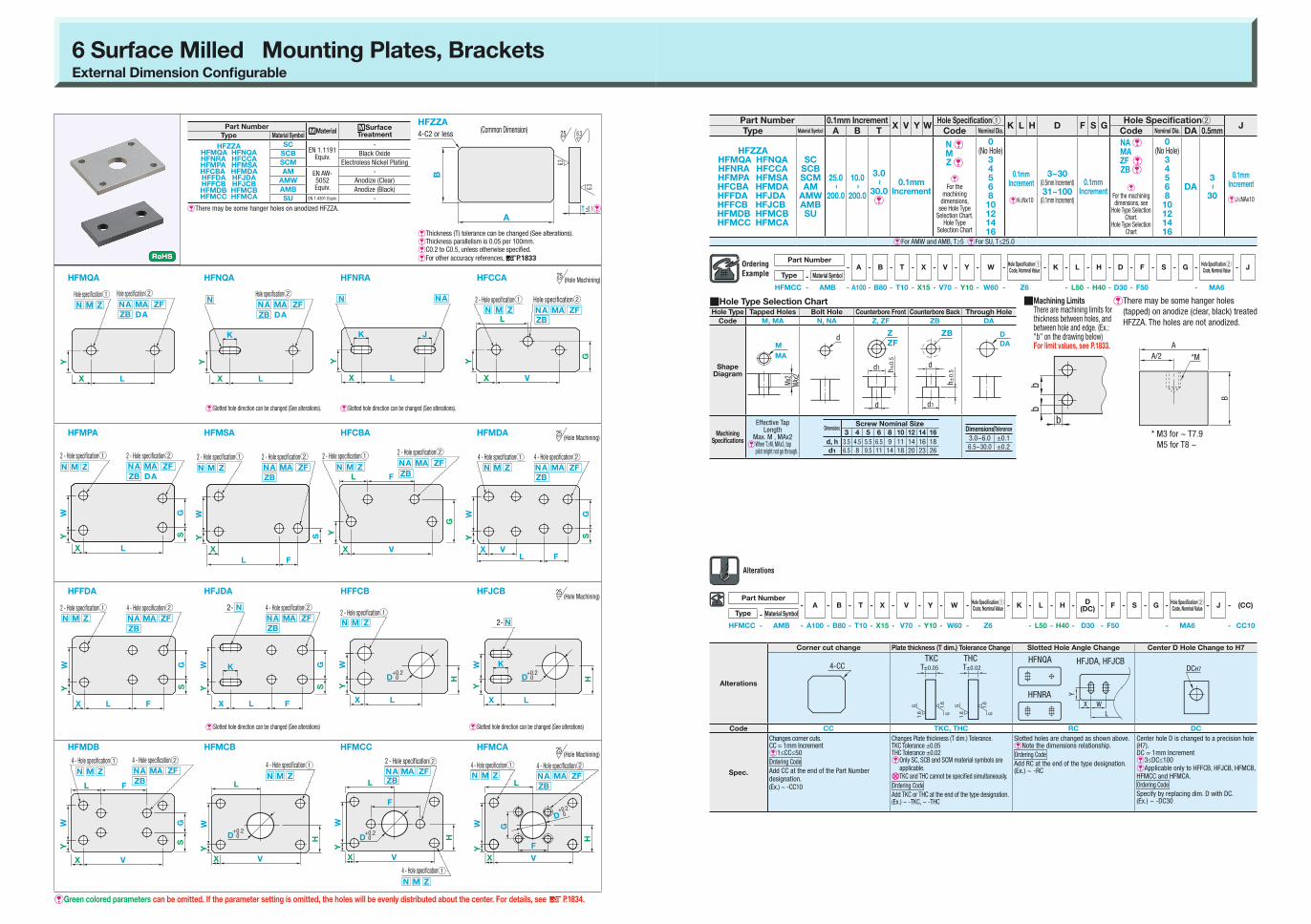
6 Surface Milled Mounting Plates, BracketsExternal Dimension Configurable
Part Number- A - B - T - X - V - Y - W -
Hole Specification1 Code, Nominal Value
- K - L - H - D - F - S - G -Hole Specification2 Code, Nominal Value
- JType - Material Symbol
HFMCC - AMB - A100 - B80 - T10 - X15 - V70 - Y10 - W60 - Z6 - L50 - H40 - D30 - F50 - MA6
A
*M
B
A/2
E��There may be some hanger holes
(tapped) on anodize (clear, black) treated
HFZZA. The holes are not anodized.
* M3 for ~ T7.9
M5 for T8 ~
Q��Machining Limits There are machining limits for thickness between holes, and between hole and edge. (Ex.: "b" on the drawing below) For limit values, see P.1833.
b
bb
YW
SG
4 - Hole specification1 4 - Hole specification2
NA
ZB
MA ZF
VX
FL
N ZM
E� Thickness (T) tolerance can be changed (See alterations).
EThickness parallelism is 0.05 per 100mm.
EC0.2 to C0.5, unless otherwise specified.
EFor other accuracy references, DP.1833
B
A
4-C2 or less
T ±0.1&
6.3
6.3
6.325
HFZZA(Common Dimension)
EGreen colored parameters can be omitted. If the parameter setting is omitted, the holes will be evenly distributed about the center. For details, see D P.1834.
E� Slotted hole direction can be changed (See alterations).E� Slotted hole direction can be changed (See alterations).
E� Slotted hole direction can be changed (See alterations) E� Slotted hole direction can be changed (See alterations)
YW
D
H
V
L
X
4 - Hole specification1
N ZM
+0.2 0
4 - Hole specification1
YW
H
4 - Hole specification2
F
G
V
L
X
NA
ZB
MA ZF
D+0.2 0
N ZM
YW
SG
4 - Hole specification24 - Hole specification1
FLX V
NA
ZB
MA ZFN ZM
HFMQA
HFMPA
HFFDA
HFMDB
HFNQA
HFMSA
HFJDA
HFMCB
HFNRA
HFCBA
HFFCB
HFMCC
HFCCA
HFMDA
HFJCB
HFMCA
D
YW
H
2 - Hole specification1
LX
N ZM
+0.2 0
4 - Hole specification22 - Hole specification1
NA MA ZF
ZB
YW
SG
FLX
N ZM
Y
X L
N
K
Hole specification2
DA
NA MA ZF
ZB
Y
X L
Hole specification1
N ZM
Hole specification2
DA
NA MA ZF
ZB
Y
G
X V
L
Hole specification2
(Hole Machining)
2 - Hole specification1
N ZM NA
ZB
MA ZF
25
Y
X L
N
K J
NA
2 - Hole specification22 - Hole specification1
YW
SG
X L
DA
NA MA ZF
ZB
N ZM
2 - Hole specification22 - Hole specification1
YW
S
X
L F
NA MA ZF
ZB
N ZM
2 - Hole specification1
Y
G
X V
FL
2 - Hole specification2
NA MA ZF
ZBN ZM
YW
H
2-
LX
N
K
D+0.2 0
4 - Hole specification22- N
NA
ZB
MA ZF
YW
SG
FLX
K
YW
H
V
F
L
X
2 - Hole specification2
N Z
4 - Hole specification1
M
D+0.2 0
NA ZF
ZB
MA
(Hole Machining)25
(Hole Machining)25
(Hole Machining)25
Part Number.Material .Surface
TreatmentType Material Symbol
HFZZAHFMQA HFNQAHFNRA HFCCAHFMPA HFMSAHFCBA HFMDAHFFDA HFJDAHFFCB HFJCBHFMDB HFMCBHFMCC HFMCA
SCEN 1.1191
Equiv.
-
SCB Black Oxide
SCM Electroless Nickel Plating
AM EN AW-5052 Equiv.
-
AMW Anodize (Clear)
AMB Anodize (Black)
SU EN 1.4301 Equiv. -
EThere may be some hanger holes on anodized HFZZA.
Part Number 0.1mm IncrementX V Y W
Hole Specification1K L H D F S G
Hole Specification2J
Type Material Symbol A B T Code Nominal Dia. Code Nominal Dia. DA 0.5mm
HFZZAHFMQA HFNQAHFNRA HFCCAHFMPA HFMSAHFCBA HFMDAHFFDA HFJDAHFFCB HFJCBHFMDB HFMCBHFMCC HFMCA
SCSCBSCMAM
AMWAMBSU
25.0
~
200.0
10.0
~
200.0
3.0
~
30.0E
0.1mm Increment
N EM Z E
EFor the
machining dimensions,
see Hole Type Selection Chart.
Hole Type Selection Chart
0(No Hole)
3456810121416
0.1mm Increment
EK≤Nx10
3~30(0.5mm Increment)
31~100(0.1mm Increment)
0.1mm Increment
NA EMAZF EZB E
EFor the machining dimensions, see
Hole Type Selection Chart.
Hole Type Selection Chart
0(No Hole)
3456810121416
DA3
~
30
0.1mm Increment
EJ≤NAx10
EFor AMW and AMB, T≥5 EFor SU, T≤25.0
QHole Type Selection ChartHole Type Tapped Holes Bolt Hole Counterbore Front Counterbore Back Through Hole
Code M, MA N, NA Z, ZF ZB DA
Shape Diagram
Machining Specifications
Effective Tap Length
Max. M , MAx2E��When T≥M, MAx3, tap
pilot might not go through.
dD
DA
ZB
d
d1
h±
0.5
Z
ZF
d
d1 h±
0.5
DimensionsScrew Nominal Size
3 4 5 6 8 10 12 14 16
d, h 3.5 4.5 5.5 6.5 9 11 14 16 18
d1 6.5 8 9.5 11 14 18 20 23 26
DimensionsTolerance
3.0~6.0 ±0.1
6.5~30.0 ±0.2
M
MA
Mx2
MAx2
Part Number- A - B - T - X - V - Y - W -
Hole Specification1 Code, Nominal Value - K - L - H -
D(DC)
- F - S - G -Hole Specification2 Code, Nominal Value - J - (CC)
Type - Material Symbol
HFMCC - AMB - A100 - B80 - T10 - X15 - V70 - Y10 - W60 - Z6 - L50 - H40 - D30 - F50 - MA6 - CC10
Alterations
Corner cut change Plate thickness (T dim.) Tolerance Change Slotted Hole Angle Change Center D Hole Change to H7
TKC THC
Code CC TKC, THC RC DC
Spec.
Changes corner cuts.CC = 1mm IncrementE1≤CC≤50
Ordering Code
Add CC at the end of the Part Number designation.(Ex.) ~ -CC10
Changes Plate thickness (T dim.) Tolerance.TKC Tolerance ±0.05THC Tolerance ±0.02E��Only SC, SCB and SCM material symbols are
applicable.
XTKC and THC cannot be specified simultaneously.
Ordering Code
Add TKC or THC at the end of the type designation.(Ex.) ~ -TKC, ~ -THC
Slotted holes are changed as shown above.ENote the dimensions relationship.
Ordering Code
Add RC at the end of the type designation.(Ex.) ~ -RC
Center hole D is changed to a precision hole (H7).DC = 1mm IncrementE3≤DC≤100
EApplicable only to HFFCB, HFJCB, HFMCB, HFMCC and HFMCA.
Ordering Code
Specify by replacing dim. D with DC.(Ex.) ~ -DC30
4-CC DCH7
1.6
G G
G G
1.6
1.6
1.6
T±0.05 T±0.02
HFNRA
HFNQA HFJDA, HFJCB
WX
L
Y

-18332 -18342
Mounting Plate, BracketOverview
1. Standard machined dimension tolerances, and thickness tolerances of sheet metals, flat bars, and rolled material
ProductDimension
Range (B Dim.)Material ~16 ~25 ~50 ~60 ~100 ~125
Flat Bars(Width
Selectable)
Allowable Tolerance (b)
EN 1.0038 Equiv.EN 1.1191 (cold
drawn) Equiv.
0-0.18
0-0.21
0-0.25
0-0.3
0-0.35
0-0.4
EN 1.4301 Equiv.0
-0.270
-0.330
-0.390
-0.730
-0.730
-0.73
<Standard Machined Dimension Tolerances>
ProductDimension Range
(A & B Dim.)6 or less
Over 6, and 30 or less
Over 30, and 120 or less
Over 120, and 400 or less
Sheet Metal (No bends)Flat Bars (Width configurable)
Rolled Aluminum, 6 Surface MilledL Angle - Welded
Allowable Tolerance (a, b)
±0.1 ±0.2 ±0.3 ±0.5
Sheet Metal (Bent Products) Allowable Tolerance (a, b) ±0.3 ±0.5 ±0.8 ±1.2
* For sheet metals, Class B Tolerance stipulated in JIS B 0408, General dimensional tolerances for parts formed by press working from sheet metal is used.* For others, JIS B 0405 Standard Machining Tolerances Class: Medium (m) is used.
Product MaterialPlate Thickness
1.0~4.5 5 6 8 10 12 15, 16, 19 20
Sheet Metal All materials Since the material is left bare, ±thicknessx0.1 will be the reference. - - - - -
Flat Bars(Width selectable - Configurable)
EN 1.0038 Equiv.EN 1.1191 (cold
drawn) Equiv.-
0-0.18
0-0.18
-0
-0.220
-0.270
-0.3-
EN 1.4301 Equiv. -0
-0.30
-0.3-
0-0.22
0-0.27
0-0.33
-
Rolled Material EN AW-5052 Equiv. - ±0.35 ±0.45 ±0.5 ±0.6 ±0.7 ±0.7 ±0.8
<Plate Thickness Tolerance>
* For some products, part of the tolerances may not be supported for the corresponding thickness, even if described on the table. For details about thickness supported per material/product, see each product page.
E��Bolt through hole (N, NA), Counterbored hole (Z, ZF, ZB) Machining per nominal diameter
Screw Nominal Size
Machining Dimensions
d, h d1
3 3.5 6.5
4 4.5 8
5 5.5 9.5
6 6.5 11
8 9 14
10 11 18
12 14 20
14 16 23
16 18 26
3-1. Machining Limits: Flat Bars, Rolled Aluminum, 6-Surface Milling, L Angles, Welded
C0.2~C0.5
E��When counterbore and wall
thickness is less than 0.5,
the counterbore may break through.
b
bb
bt
A±a
A±a
B±b
B±b
A±0.15
B±b
6.3
3.2
6.3
3.2
25
25
Hole Type Bolt Hole Counterbored Holes Through Hole Tapped Holes (Coarse Thread)
Code N, NA Z, ZF, ZB, ZBA D, DA M, MA
Shape Diagram
Effective tap depth will be the max. nominal tap dia.x2.EX.) Specify M6 Effective depth is 12
Details
Through hole for screws/bolts.Use bolt nominal diameter for specifying.(ESee chart on right for machining dimensions)
Counterbored hole for screws/bolts.Use bolt nominal diameter for specifying.(ESee chart on right for machining dimensions)
Through hole whose diameter can be specified in 0.5mm or 1mm increments.
Coarse Thread TapUse tap hole size for specifying.
E
2. Hole Type
M
MA
D
DA
Z
ZF, ZB, ZBA
d
d1 h±
0.5
E
4. Hole Specifying Example
1For each of # encased hole symbols, the applicable hole can be eliminated.
2Holes can be reduced by specifying the hole pitch as 0.
3� When holes are evenly located about the center, the green color parameter can be omitted.
Specify hole position parameters and hole as 0.
FASBS-SP-T2.3-A20-B20-L20-X0-H0-N0-Y6-V8-S12-NA3-K6
Ordering Code
Ordering Example
Specify hole pitch parameter with 0.
HRJDA-SCB-A80-B50-T6-X15-Y10-W30-N5-K10-L45-F0-S10-G30-MA5
Ordering Code
Ordering Example
FALBS-SP-T2.3-A20-B20-L20-H15-N3-V8-S12-NA3(Same as FALBS-SP-T2.3-A20-B20-L20-X10-H15-N3-Y6-V8-S12-NA3)
Ordering Example
VY
L
X
K
S
H
2-Hole specification2
NA
Hole specification1
N
M
DA
4-C2 or less
20
86
2-NA3
12
6
15
10 2-N5 2-MA5 4-C2 or less
45
80
30
10
30
10
50
L
X
HS
VY
2-Hole specification2
NA
MA
Hole specification1
N
M
DA
K
L F
W
X
Y
GS
NA MA
ZF ZBN
4 - Hole specification2
1
6 8
20
2-NA3
N3
10
15
12
4-C2 or less
EMachining below the indicated limits is not possible.q b Conditional Values
Specified Values Specified Values (Nominal) b Conditional Values
Hole Type, Code 3 4 5 6 8 10 12 14 16
Tapped Holes M, MA 0.8 0.8 0.8 1 1 1 1 1.5 1.5
Bolt Hole N, NA 0.8 0.8 1 1 1 1 1 1 1
Counterbored Holes Z, ZF, ZB 0.8 0.8 1 1 1 1 1 1 1
Specified Values Per Specified Value (Hole Diameter) b Conditional Values
Hole Type, Code 3.0~5.0 5.1~25.0 25.1~50.0 50.5~100.0
Through Hole D, DA 0.8 1 2 3
Precision Hole (H7) DC, DFC 1.5 2 3 4
Specified Values Specified Values (Nominal) t Conditional Values
Hole Type, Code 3 4 5 6 8 10 12 14 16
Counterbored Holes Z, ZF, ZB 0.8 0.8 0.8 1 1 1 1 1.5 1.5
q t Conditional Values
3-2. Machining Limits: Sheet Metal
EMachining below the indicated limits is not possible.
E The hole may be deformed if specified at the limit value shown above.
Plate Thickness f (Distance between the hole and the bend)b ( )Distance between
the hole and the end face
h gEN 1.0330 Equiv. EN 1.0320 Equiv.
(hot coiled)
EN AW-5052
Equiv.
EN 1.4301 Equiv.(2B)
Through Hole Tapped Holes Toleranced Hole: Slotted Hole parallel to bendL Bend Z, Convex Bend L Bend Z, Convex Bend
1.0 - 1.0 2 3 3 5.5 3.5 1 5.5 5.5
1.6 1.5 1.5 2 3.5 3 6 4 1 6 6
2.3 2.0 2.0 2 4.5 3 7 5 1.5 7 7
3.2 3.0 3.0 2 6.5 3 9 7 1.5 9 9
4.5 4.0 4.0 3 7.5 4 11 8 (9) 2 11 11
6.0 5.0 5.0 3 14 4 16 15 2.5 16 18
E Slotted hole f parallel to T4.0 - 4.5 will be (9).
h bf
b fg
b
bb
NoticeL bending machining limits have been greatly relaxed.Holes can be placed closer to the bends than before!
(Catalog published in 2012)
ConventionallyAfter the change
d

-18352 -18362
Sheet Metal Mounting Plates / BracketsCenter Symmetrical Type
eAs opposed to the "Dimension Configurable Type" on the next page, the external dimension tolerance guarantee is ±1.0.
Part NumberMMaterial
SSurface
TreatmentType Material Symbol
JSDASJSAASJSHDS
SP EN 1.0330 Equiv.e
-
SPU Trivalent Chromate (Clear)
SPK Trivalent Chromate (Black)
AMEN AW-5052
Equiv.
-
AMW Anodize (Clear)
AMB Anodize (Black)
SUD EN 1.4301 Equiv.(2B) -e4.5 thickness type is EN 1.0320 Equiv. (hot coiled) material.
T
4-C2 or less
B±
1.0
A±1.0
(Common Dimension)
JSHDS
L
G
N M
4 - Hole specificationD+0.2
0
JSAAS
L
G
N M
4 - Hole specificationJSDAS
L
N M
2 - Hole specification
QSpecifications
e1.Burr height 0.1 or less
QMachining Limits
e2. There are machining limits for thickness between holes, and between hole and edge. (Ex. "b" on the right diagram)
For limit values, see dP.1834.
b
bb
Part Number- A - B - T - L - G -
Code,
Nominal Value- D
Type - Material Symbol
JSDAS - SP - A80 - B40 - T3.2 - L30 - N4
JSAAS - SPU - A100 - B50 - T2.3 - L90 - G40 - M3
JSHDS - SUD - A100 - B80 - T2.0 - L80 - G60 - N5 - D30
Part Number 1mm Increment SelectionL G
Hole SpecificationD
Type Material Symbol A B T Code / Specify Method
JSDASJSAASJSHDS
SPSPUSPKAM
AMWAMBSUD
10
~
200
10
~
100
EN 1.0330 Equiv.
(EN 1.0320 Equiv. (hot
coiled))
2.33.24.5
EN AW-5052 Equiv.EN 1.4301
Equiv.
2.03.04.0
1mm Increment
N (Bolt Hole)e3, 4, 5, 6, 8, 10
(Select) 3~30(0.5mm Increment)
M (Tapped Holes)3, 4, 5, 6, 8, 10
(Select)
N Specified Value 3 4 5 6 8 10
Through Hole Dia. (d) 3.5 4.5 5.5 6.5 9 11
eN Machining Dimension
QHole Type Selection Chart
Hole Type Bolt Hole Tapped Holes Through Hole
Code N M D
Shape Diagram
M D+0.2 0
dF
e��For d dimension, see "N Machining Dimensions" on lower section of specification chart.
Material Symbol
A B TUnit Price Volume Discount Rate
1~3 pcs. 4 ~7 pcs. 8 ~ 19 pcs. 20 ~ 39 pcs. 40 ~ 200 pcs.
SP
10
~
100
10
~
50
2.3
3.2
4.5
51
~
100
2.3
3.2
4.5
101
~
200
10
~
50
2.3
3.2
4.5
51
~
100
2.3
3.2
4.5
AM
10
~
100
10
~
50
2.0
3.0
4.0
51
~
100
2.0
3.0
4.0
101
~
200
10
~
50
2.0
3.0
4.0
51
~
100
2.0
3.0
4.0
SUD
10
~
100
10
~
50
2.0
3.0
4.0
51
~
100
2.0
3.0
4.0
101
~
200
10
~
50
2.0
3.0
4.0
51
~
100
2.0
3.0
4.0
QJSDAS Body Price QJSAAS Body Price
Material Symbol
A B TUnit Price Volume Discount Rate
1~3 pcs. 4 ~7 pcs. 8 ~ 19 pcs. 20 ~ 39 pcs. 40 ~ 200 pcs.
SP
10
~
100
10
~
50
2.3
3.2
4.5
51
~
100
2.3
3.2
4.5
101
~
200
10
~
50
2.3
3.2
4.5
51
~
100
2.3
3.2
4.5
AM
10
~
100
10
~
50
2.0
3.0
4.0
51
~
100
2.0
3.0
4.0
101
~
200
10
~
50
2.0
3.0
4.0
51
~
100
2.0
3.0
4.0
SUD
10
~
100
10
~
50
2.0
3.0
4.0
51
~
100
2.0
3.0
4.0
101
~
200
10
~
50
2.0
3.0
4.0
51
~
100
2.0
3.0
4.0
QJSHDS Body Price
Material Symbol
A B TUnit Price Volume Discount Rate
1~3 pcs. 4 ~7 pcs. 8 ~ 19 pcs. 20 ~ 39 pcs. 40 ~ 200 pcs.
SP
10
~
100
10
~
50
2.3
3.2
4.5
51
~
100
2.3
3.2
4.5
101
~
200
10
~
50
2.3
3.2
4.5
51
~
100
2.3
3.2
4.5
AM
10
~
100
10
~
50
2.0
3.0
4.0
51
~
100
2.0
3.0
4.0
101~
200
10
~
50
2.0
3.0
4.0
51
~100
2.0
3.0
4.0
SUD
10
~
100
10
~
50
2.0
3.0
4.0
51
~
100
2.0
3.0
4.0
101
~
200
10
~
50
2.0
3.0
4.0
51
~
100
2.0
3.0
4.0
[Surface Treatment Charges]
Material Symbol
A B TUnit Price Volume Discount Rate
1~3 pcs. 4 ~7 pcs. 8 ~ 19 pcs. 20 ~ 39 pcs. 40 ~ 200 pcs.
SPUSPK
10
~
100
10
~
50
2.3
3.2
4.5
51
~
100
2.3
3.2
4.5
101
~
200
10
~
50
2.3
3.2
4.5
51
~
100
2.3
3.2
4.5
AMWAMB
10
~
100
10
~
50
2.0
3.0
4.0
51
~
100
2.0
3.0
4.0
101
~
200
10
~
50
2.0
3.0
4.0
51
~
100
2.0
3.0
4.0
t Add surface treatment charge to example calculated body price. (Ex.) For JSDAS-SPU-A80-B40-T2.3-L30-N4,
Main Body Price + Surface Treatment Charge = Price

-18372 -18382
Sheet Metal Mounting Plates / BracketsDimension Configurable Type
eAs opposed to the "Center Symmetrical Type" on the previous page, general tolerance (dP.1833) is the guaranteed value for external dimensions.
e4.5, 6.0 thickness type is EN 1.0320 Equiv. (hot coiled) material.
Part NumberMMaterial
SSurface
TreatmentType Material Symbol
JTDZS
JTDAS JTHAS
JTDBS JTHBS
JTDCS JTHDS
JTMAS JTHES
JTAAS JTABS
JTBAS JTBBS
JTKAS JTACS
JTNAS JTADS
SP
EN 1.0330 Equiv.e
-
SPB Black Oxide
SPU Trivalent Chromate (Clear)
SPK Trivalent Chromate (Black)
AMEN AW-5052
Equiv.
-
AMW Anodize (Clear)
AMB Anodize (Black)
SUD EN 1.4301 Equiv.(2B) -
QHole Type Selection Chart
Hole Type Bolt Hole Tapped Holes (Coarse Thread) Through Hole
Code N, NA M, MA D, DA
Shape Diagram
dF M
MA
D, DA+0.2 0
e��For d dimension, see "N, NA Machining Dimensions" on lower section of specification chart.
Part Number- A - B - T - X - F - Y - G -
Hole Specification1
Code, Nominal Value- K - L - V - S - W -
Hole Specification2
Code, Nominal Value- D - J
Type - Material Symbol
JTDAS - SP - A80 - B50 - T3.2 - X10 - N5 - L30
JTAAS - SUD - A150 - B80 - T2.0 - X10 - Y10 - N3 - L100 - S10 - W50 - NA4
Part Number- A - B - T - X - F - Y - G -
Hole Specification1Code, Nominal
Value- K - L - V - S - W -
Hole Specification2Code, Nominal
Value- D - J - (CC, RC)
Type - Material Symbol
JTDAS - SP - A80 - B50 - T3.2 - X10 - N5 - L30 - CC5
Alteration
Slotted Hole Angle Change Corner cut
Code RC CC
Spec.
Slotted holes are changed as shown above.
eNote the dimensions relationship
ORDERING CODE
Add RC at the end of the type designation.(Ex.) ~ -RC
CC = 1mm Increment
1≤CC≤10
ORDERING CODE
Add CC at the end of the Part Number designation.
(Ex.) ~ -CC5
JTDBS
4-CCJTHBS JTBASJTBBS
JTDCS
GX
L
Y
Part Number 1mm Increment SelectionX F Y G
Hole Specification1K L V S W
Hole Specification2D J
Type Material Symbol A B T Code / Specify Method Code / Specify Method
JTDZS
JTDAS JTHAS
JTDBS JTHBS
JTDCS JTHDS
JTMAS JTHES
JTAAS JTABS
JTBAS JTBBS
JTKAS JTACS
JTNAS JTADS
SP
SPB
SPU
SPK
AM
AMW
AMB
SUD
10
~
300
e
5
~
300
e
EN 1.0330 Equiv.(EN
1.0320 Equiv. (hot
coiled))
1.62.33.24.56.0
EN AW-5052 Equiv.
1.52.03.04.05.0
EN 1.4301 Equiv.
1.01.52.03.04.05.0
0.1mm
Increment
N (Bolt Hole) e0, 3, 4, 5
6, 8, 10
(Select) 0.1mm Increment
eK≤Nx10
NA (Bolt Hole)e0, 3, 4, 5, 6, 8, 10
(Select)
3~30(0.5mm
Increment)
0.1mm Increment
eJ≤NAx10
MA (Tapped Holes)0, 3, 4, 5, 6, 8, 10
(Select)M (Tapped Holes)
0, 3, 4, 5
6, 8, 10
(Select)
DA (Through Hole)3~30
(0.5mm Increment)
eFor types other than JTD# #, JTMAS and JTNAS, A≥15, and B≥15 eFor Thickness 6.0, B≥6eIf the specified hole location is close to the edges, the hole may be deformed but will be machined as specified if within machining limits.
N, NA specified Value 0 3 4 5 6 8 10
Through Hole Dia. (d) (No Hole) 3.5 4.5 5.5 6.5 9 11
eN, NA machining dimensions
e��There may be some hanger holes on anodized JTDZS. (See Specifications, Machining Limits)
eGreen colored parameters can be omitted. If the parameter setting is omitted, the holes will be evenly distributed about the center. For details, see dP.1834.
Y
LX
Hole specification1 Hole specification2
N M NA MA +0.2
0 DA+0.2
0 DAK
X L
Y
Hole specification1 Hole specification2
N NA MA
K J
X L
Y
Hole specification1 Hole specification2
N NA
Y S
Hole specification2NA MA
2 - Hole specification1
N M
X F
L
JTDAS JTDBS
JTBAS
JTHBS
JTBBS
JTDCS
JTKAS
JTHDS
JTACS
JTMAS
JTNAS
JTHES
JTADS
JTAAS
JTHAS
JTABS
eSlotted hole direction can be changed (See alterations)
eSlotted hole direction can be changed (See alterations)
eSlotted hole direction can be changed (See alterations)
eSlotted hole direction can be changed (See alterations)eSlotted hole direction can be changed (See alterations)
JTDZS
4-C2 or less
BTA
(Common Dimension)
+0.20 DA
+0.20 DA
Y SWG
X
L
2 - Hole specification1
N M
V
4 - Hole specification2NA MA
Y SWG
X
L
2 - Hole specification1
N
V
4 - Hole specification2NA MA
K
Y SWG
X F
L
4 - Hole specification1N M
V
4 - Hole specification2NA MA
Y
SWG
X F
L
4 - Hole specification1
N M
V
4 - Hole specification2NA MA
E� 1. For tolerances, see DP.1833.
E� 2. Burr height 0.1 or less
E� 3. Slotted holes may be shaped as shown below depending on dimensions. (No negative effects on mounting functionality)
QSpecifications, Machining Limits
b
bb5 Ø3
5
E5. There are machining limits for thickness between holes, and between hole and edge. (Ex.: "b" on the drawing below)
For limit values, see dP.1834.
E4. Anodized JTDZS There are hanger holes above T4.
A B T
Body Price Unit Price Surface Treatment Charge (Body Price+)
JTDZS JTDAS JTHASJTAAS JTDBSJTKAS JTDCSJTMAS JTNAS
JTBAS JTABSJTBBS JTHESJTACS JTADS
JTHBS JTHDSEN
1.0330 Equiv.
EN AW-5052 Equiv.
EN 1.0330 Equiv.
EN 1.0320 Equiv. (hot
coiled)
EN AW-5052
Equiv.
EN 1.4301 Equiv.
EN 1.0330 Equiv.
EN 1.0320 Equiv. (hot
coiled)
EN AW-5052
Equiv.
EN 1.4301 Equiv.
EN 1.0330 Equiv.
EN 1.0320 Equiv. (hot
coiled)
EN AW-5052
Equiv.
EN 1.4301 Equiv.
EN 1.0330 Equiv.
EN 1.0320 Equiv. (hot
coiled)
EN AW-5052
Equiv.
EN 1.4301 Equiv.
EN 1.0330 Equiv.
EN 1.0320 Equiv. (hot
coiled)
EN AW-5052
Equiv.
EN 1.4301 Equiv.
Black Oxide Trivalent
Chromate (Clear, Black)
Anodize (Clear)
Anodize (Black)
SP AM SUD SP AM SUD SP AM SUD SP AM SUD SP AM SUDSPBSPUSPK
AMW AMB
10~100
5~1001.0~1.62.0~3.24.0~6.0
101~2001.0~1.62.0~3.24.0~6.0
201~3001.0~1.62.0~3.24.0~6.0
101~200
5~1001.0~1.62.0~3.24.0~6.0
101~2001.0~1.62.0~3.24.0~6.0
201~3001.0~1.62.0~3.24.0~6.0
201~300
5~1001.0~1.62.0~3.24.0~6.0
101~2001.0~1.62.0~3.24.0~6.0
201~3001.0~1.62.0~3.24.0~6.0
t Add surface treatment charge to example calculated body price. (Ex.) For JTDZS-SPB-A100-B50-T3.2,
Main Body Price + Surface Treatment Charge = Price
+0.20
+0.20
+0.20 +0.2
0 +0.2
0
DA+0.2
0 DA
Y SWG
2 - Hole specification1
N M
2 - Hole specification2NA MA
X L
Y SWG
2 - Hole specification2NA MA
X L
2 - Hole specification1N
K
Y
S
G
2 - Hole specification2NA MA
2 - Hole specification1
N M
X
L V
Y S
2 - Hole specification2NA MA
2 - Hole specification1N M
X F
L V
Y
S
G
X L
2 - Hole specification1
N M
D
Y
S
G
X L
D2 - Hole specification1
N
K
Y
S
G
X F
L D
4 - Hole specification1
N M
V
Y
S
G
X F
L D
4 - Hole specification1 2 - Hole specification2N M NA MA