flash technology ftm 190
TRANSCRIPT

Flash Technology, 332 Nichol Mill Lane, Franklin, TN 37067www.spx.com/en/flash-technology
(615) 261-2000
FLASH TECHNOLOGYFTM 190
Monitoring SystemReference Manual
Part Number F7911900SERIAL NUMBER


i Revision 5 – 6/26/2014 FTM 190
Front Matter
AbstractThis manual contains information and instructions for installing, operating and maintainingthe FTM 190 Monitoring System.
CopyrightCopyright © 2014, Flash Technology®, Franklin, TN, 37067, U.S.A.
All rights reserved. Reproduction or use of any portion of this manual is prohibited withoutexpress written permission from Flash Technology and/or its licenser.
Trademark AcknowledgementsFlash Technology® is a registered trademark name.
All trademarks and product names mentioned are properties of their respective companies,and are recognized and acknowledged as such by Flash Technology.
DisclaimerWhile every effort has been made to ensure that the information in this manual is complete,accurate and up-to-date, Flash Technology assumes no liability for damages resulting fromany errors or omissions in this manual, or from the use of the information contained herein.Flash Technology reserves the right to revise this manual without obligation to notify anyperson or organization of the revision.
In no event will Flash Technology be liable for direct, indirect, special, incidental, orconsequential damages arising out of the use of or the inability to use this manual.
WarrantyFlash Technology warrants all components, under normal operating conditions, for 1 year.
Personnel Hazard Warning
Dangerous VoltagesDangerous line voltages reside in certain locations in this equipment. Flash Technology hasincorporated every practical safety precaution, exercise extreme caution at all times whenyou expose circuits and components, and when you operate, maintain, or service thisequipment.
Avoid Touching Live CircuitsAvoid touching any component or any part of the circuitry while the equipment is operating.Do not change components or make adjustments inside the equipment with power on.
Disconnecting PowerWhen removing power from the equipment, ensure that the red wire to the battery isdisconnected first. Reconnect battery after work is completed.

FTM 190 Revision 5 – 6/26/2014 ii
Table of Contents
Front Matter ............................................................................................................................... iAbstract .................................................................................................................................. iCopyright ............................................................................................................................... iTrademark Acknowledgements ............................................................................................. iDisclaimer .............................................................................................................................. iWarranty ................................................................................................................................ i
Personnel Hazard Warning ........................................................................................................ iDangerous Voltages ............................................................................................................... iAvoid Touching Live Circuits ............................................................................................... iDisconnecting Power ............................................................................................................. i
Table of Contents...................................................................................................................... iiList of Figures .......................................................................................................................... iiiList of Tables ........................................................................................................................... iiiSection 1 – Introduction............................................................................................................ 1
Introduction........................................................................................................................... 1Description............................................................................................................................ 1Specifications........................................................................................................................ 1
Section 2 – Mounting and Installation ...................................................................................... 2Unpacking ............................................................................................................................. 2Wireless Modem Service Verification.................................................................................. 2Finding the Best Installation Location.................................................................................. 2Installation............................................................................................................................. 4
Recommended Tools ........................................................................................................ 4FTM 190 Access ............................................................................................................... 4Mounting........................................................................................................................... 4AC Power Wiring ............................................................................................................. 4Dry Contact Input Wiring ................................................................................................. 6RS-485 Wiring.................................................................................................................. 6Antenna Mounting Bracket............................................................................................... 6Grounding ......................................................................................................................... 6
Status Indicator LED’s.......................................................................................................... 9Section 3 – Activation............................................................................................................. 13
Monitoring .......................................................................................................................... 13Section 4 – Web Interface....................................................................................................... 14
Web Interface...................................................................................................................... 14Initial Setup......................................................................................................................... 14Configuration Menu............................................................................................................ 14
Device ............................................................................................................................. 15Monitoring ...................................................................................................................... 17Network........................................................................................................................... 18Cellular Modem .............................................................................................................. 18SNMP Labels .................................................................................................................. 18
Web Interface...................................................................................................................... 19Web Interface...................................................................................................................... 22
Section 5 – Troubleshooting ................................................................................................... 23Section 6 – Recommended Spare & Replaceable Parts.......................................................... 25

iii Revision 5 – 6/26/2014 FTM 190
Customer Service ................................................................................................................ 25Ordering Parts ..................................................................................................................... 25
Return Material Authorization (RMA) Policy........................................................................ 28
List of Figures
Figure 2-1 – FTM 190 Internal Wiring..................................................................................... 3Figure 2-2 – Enclosure Mounting Footprint ............................................................................. 5Figure 2-3 – Dry Contact Input Label....................................................................................... 7Figure 2-4 – Antenna Types ..................................................................................................... 7Figure 2-5 – Antenna Universal Mounting Bracket ................................................................. 8Figure 2-6 – PCB 1 Layout and External Wiring ................................................................... 10Figure 2-7 – RS-485 Installation with FTS 36XX.................................................................. 11Figure 2-8 – RS-485 Installation with FTB 3XX (29038XX PCB) ....................................... 12Figure 6-1 – Component Locations ........................................................................................ 26
List of Tables
Table 2-1 – PCB 1 LED’s......................................................................................................... 9Table 5-1 – Troubleshooting –Power ..................................................................................... 23Table 5-2 – Troubleshooting – Cellular Connection .............................................................. 24Table 6-1 – Major Replaceable Parts...................................................................................... 27Table 6-2 – Optional Items ..................................................................................................... 27


1 Revision 5 – 6/26/2014 FTM 190
Section 1 – Introduction
IntroductionThe FTM 190 Monitoring Unit providesCellular Eagle 2.0 remote monitoring ofFlash Technology FTB 3XX mediumintensity strobe systems (29038XX PCBrequired) and all FLC series controllers viaRS 485. The FTM 190 can also monitorup to eight dry contact inputs. The unit isequipped with an internal battery back-upwhich allows continued operation andalarm reporting during power failures.
Dry contacts are typically alarm relaysprovided by equipment for externalmonitoring of alarm conditions. Eachinput of the FTM 190 can be configuredby Flash Technology’s NOC (NationalOperations Center) to alarm on either openor closed status. Alarm on open ispreferred for fail safe monitoring.
All Cellular Eagle alarm andcommunication monitoring is handled bythe NOC.
Note: If the FTM 190 is equipped with awireless modem, power-up the system on-site to ensure wireless service is availablebefore permanently installing or wiring thesystem. Refer to Section 2 for detailedinstructions.
DescriptionThe internal wiring of the unit is shown inFigure 2-1. A component locationdiagram is shown in Figure 6-1. The drycontact inputs are located on J6 and J7 ofPCB 1 (PN 2410000) as shown in Figure2-6.
SpecificationsPhysical
Dimensions H x W x D (millimeters)13.51” x 11.32” x 7.11”(343.15 x 287.5 x 180.6)
Weight (kilograms)10 lbs. (4.5)
ElectricalAC Voltage 120 VAC, 60 HzPower 10 VABattery Operation 2+ hrs

FTM 190 Revision 5 – 6/26/2014 2
Section 2 – Mounting and Installation
UnpackingInspect shipping cartons for signs ofdamage before opening them. Checkpackage contents against the packing listand inspect each item for visible damage.Report damage claims promptly to thefreight handler.
Wireless Modem ServiceVerificationIf the FTM 190 is equipped with awireless modem, service at the locationwhere the unit will be installed must beverified before it is installed. Thefollowing steps will verify that service isavailable.
Figure 2-1 shows an internal wiringdiagram of the unit with the input powerconnections on TB1. Temporarily apply120 VAC to the unit at TB1 terminals“L1”, “N”, and . The LEDs located onPCB1 will illuminate during theinitialization process. Up to two minutesmay be required for signal strengthindication to occur on PCB1. The SignalStrength Indicator LEDs labeled “SSI”(see Figure 2-6) will light up to indicatethe strength of the available signal. Aftera wireless signal is found, the unit willattempt to connect to the NOC. While
communication is underway, the“ACTIVE” LED will blink and the“STATUS” LED will be off. Whencommunication is successfully completed,the “ACTIVE” LED will be off and the“STATUS” LED will be on to indicatethat all information has beencommunicated successfully.
Note: LED indicators on the modemprovide further details on cellularconnection. See Figure 2-1 “ModemLED’s” table for a description of eachLED.
Finding the Best InstallationLocationMove the external antenna to variouslocations to determine the maximumsignal strength available at the site, asindicated by the number of Signal StrengthIndicator LEDs labeled “SSI” on PCB1which are lit. The SSI LED’s will indicatethe Signal Strength approximately 35seconds after the antenna is moved. Thiswill help determine the location where theFTM 190 should be mounted.
Upon successful completion of these steps,shut off power to the unit and proceedwith installation.

3 Revision 5 – 6/26/2014 FTM 190
OF
FO
N
NC NO NC NOC C
- -+ +
Flash Technology
12V
L A N
S V C
L N K
Figure 2-1 – FTM 190 Internal Wiring

FTM 190 Revision 5 – 6/26/2014 4
Installation
WARNING!Read the warning on Page i now.Disconnect primary power before openingenclosures.
Recommended Tools
Flash Technology recommends thefollowing tools for installation andmaintenance:• Tools for securing mounting hardware• 1/8” non-flared flat blade screw driver• #2 Phillips® head screwdriver• Long-nose pliers• Wire Strippers• Digital volt-ohm meter• Level• Cable Ties• Camera (for documentation)
FTM 190 Access
The cover is hinged and secured withlatches. Release the latches and swing thecover open for internal access.
Mounting
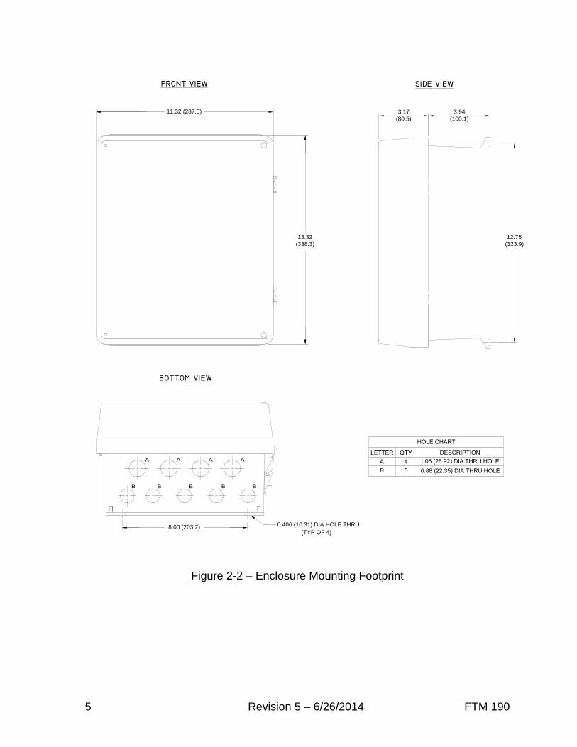
The FTM 190 enclosure mounting outlineand dimensions are shown in Figure 2-2.Ensure that adequate space exists aroundthe equipment for access duringinstallation, maintenance and servicing.Mounting hardware is not provided unlessit is ordered as part of an installation kit.
AC Power Wiring
The AC line connections are made at“L1”, “N”, and located on TB1 in the
lower left of the unit. Also located onTB1 is a Metal Oxide Varistor (VR1) anda fuse (F1). The incorporation of VR1 andF1 on TB1 provides increased protectionagainst AC power transients. The F1 fuseholder also acts as a power disconnect tothe unit. Grasp the fuse holder at the topand pull down to disconnect power.Connect 120 VAC power to terminalblock TB1 (L1, N, ) as shown in Figure2-1.
Note: Leave power turned off until youare ready for activation (see Section 3).
The terminal block uses spring-cagecontacts to provide rugged, trouble-freeconnections which are vibration-proof andgas-tight, thus providing long-termstability. The conductor contact force isdetermined by the spring tension and so isindependent of the user tightening torqueas with screw type terminals.
To install a wire, follow these steps:1. Strip the insulation, exposing 0.4
inch (10 mm) or more ofconductor.
2. Insert a standard 1/8” widthscrewdriver into the rectangularslot and push. This causes thespring clip to open.
3. Insert the conductor fully into theround terminal compartment andthen remove the screwdriver. Theconductor automatically makescontact.
4. Check that contact is made toconductor metal and not insulation.
5 Revision 5 – 6/26/2014 FTM 190
13.32(338.3)
11.32 (287.5)
0.406 (10.31) DIA HOLE THRU
(TYP OF 4)
3.17(80.5)
3.94(100.1)
12.75(323.9)
8.00 (203.2)
A A A A
B B B B B
Figure 2-2 – Enclosure Mounting Footprint

FTM 190 Revision 5 – 6/26/2014 6
Dry Contact Input Wiring
Connect the equipment to be monitoredvia dry contact inputs as shown in Figure2-6. A label has been provided on theinside cover of the unit to record eachinput, up to eight (8), that is connected.Figure 2-3 depicts the dry contact inputlabel.
Note: Each input can be configured byFlash Technology’s National OperationsCenter (NOC) to alarm on either openor closed status. Alarm on open ispreferred for fail safe monitoring.
RS-485 Wiring
Connect the Flash Technology FLCController or FTB 3XX medium intensitystrobe system (29038XX PCB required) tobe monitored via RS-485 as shown inFigures 2-7 and 2-8. Figure 2-6 shows thelayout of PCB1 located in the FTM 190.
Antenna Mounting Bracket
An Antenna Universal Mounting BracketKit (PN 1905355) is supplied with unitsequipped with a wireless modem. Thebracket provides multiple mountingoptions for the antenna; permittinginstallation in the optimum location forsignal strength and reliablecommunication. The bracket’s designpermits mounting on wall, Uni-strut, orpole (Figure 2-5). Regardless of themounting method selected, the antennabracket must be grounded directly to thesite grounding system with a minimum 14AWG ground wire. Observe propergrounding procedures.
The bracket is made from ferrous metaland galvanized for long life. The bracket’stop plate accommodates either themagnetic mount or body mount styleantenna as shown in Figure 2-4. The
cellular antenna must be mounted in thecenter position of the bracket. The bracketalso permits mounting of a photodiode (orphotocell) in either of the two side holeson the top plate.
The FTM 190 is shipped with the antennapreinstalled and the antenna cable’s SMAconnector torqued to specification onto themodem antenna connector for optimalperformance. Do not remove or disconnectunless replacing the modem or antenna.
To install the bulkhead mount styleantenna, loosen the antenna mounting nutand washer and slide the antenna mountthrough the bracket’s center holeslot. Tighten the hardware.
Important! For best communicationperformance and to minimizepotential for surge damage to themodem radio module, it is veryimportant that the supplied antennamounting bracket be used formounting the antenna and that thebracket be grounded with a minimum14 AWG Ground wire connected tothe site Grounding System. Also, ifany excess antenna cable is coiledup, the coil diameter must not beless than 18 inches.
Grounding
To provide increased immunity fromlightning damage to the FTM 190, it isessential that the Ground Lug located inthe lower left corner of the baseplate(Figure 2-1) be properly connected by aNo. 2 AWG conductor to the siteGrounding System. Observe propergrounding procedures.

7 Revision 5 – 6/26/2014 FTM 190
2
3
4
5
6
7
8
1
Figure 2-3 – Dry Contact Input Label
Figure 2-4 – Antenna Types
Body Mount AntennaAT&T or Verizon
Magnetic Mount AntennaVerizon Only

FTM 190 Revision 5 – 6/26/2014 8
Figure 2-5 – Antenna Universal Mounting Bracket
Note: Verizon dual band magnetic mount antenna shown.
Wall MountUse screws to mount to the inside or outside wall of ashelter.(Screws are not included in the kit.)
Horizontal Uni-strut MountUse spring-nuts to mount to Uni-strut.(Spring-nuts are not included in the kit.)
Vertical Pole or H-frame post MountUse 3” U-bolt (included) to mount to pole or H-frame post.The bracket permits use of larger U-bolts, up to 5”.
9 Revision 5 – 6/26/2014 FTM 190
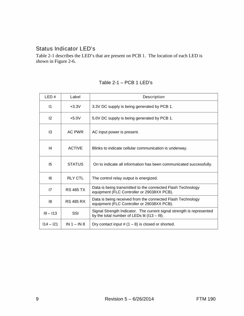
Status Indicator LED’sTable 2-1 describes the LED’s that are present on PCB 1. The location of each LED isshown in Figure 2-6.
Table 2-1 – PCB 1 LED’s
LED # Label Description
I1 +3.3V 3.3V DC supply is being generated by PCB 1.
I2 +5.0V 5.0V DC supply is being generated by PCB 1.
I3 AC PWR AC input power is present.
I4 ACTIVE Blinks to indicate cellular communication is underway.
I5 STATUS On to indicate all information has been communicated successfully.
I6 RLY CTL The control relay output is energized.
I7 RS 485 TXData is being transmitted to the connected Flash Technologyequipment (FLC Controller or 29038XX PCB).
I8 RS 485 RXData is being received from the connected Flash Technologyequipment (FLC Controller or 29038XX PCB).
I9 – I13 SSISignal Strength Indicator. The current signal strength is representedby the total number of LEDs lit (I13 – I9).
I14 – I21 IN 1 – IN 8 Dry contact input # (1 – 8) is closed or shorted.

FTM 190 Revision 5 – 6/26/2014 10
DC
AU
X
AC
FA
IL
J11
DC
PO
WE
RIN
PU
TS
MO
DE
MP
WR
J10
12
V
GN
D
Fla
sh
Te
chn
olo
gy
J8J9
I9 I10
I11
I12
I13
SS
I
I4 I5 I6 I7 I8
AC
TIV
ES
TA
TU
SR
LY
CT
LR
S4
85
TX
RS
48
5R
X
I1 I2 I3
+3
.3V
+5
.0V
AC
PW
R
I14
I15
I16
I17
IN1
IN2
IN3
IN4
I18
I19
IN5
IN6
IN7
IN8
I20
I21
+ --
RX
TX
GN
DB
AA
BG
ND
NC
NO
CO
M
DR
YC
ON
TA
CT
INP
UT
SR
EL
AY
OU
TR
S4
85
RS
232
/48
5R
S2
32
J5J6
J7
IN1
IN2
IN3
IN4
IN5
IN6
IN7
IN8
RX
TX
GN
D
INP
UT
#1
INP
UT
#2
INP
UT
#3
INP
UT
#4
INP
UT
#5
INP
UT
#6
INP
UT
#7
INP
UT
#8
FL
AS
HT
EC
HN
OL
OG
YF
LC
CO
NT
RO
LL
ER
OR
FT
B3
XX
(29
03
8X
XP
CB
)N
OT
E:
EA
CH
INP
UT
CA
NB
EC
ON
FIG
UR
ED
BY
FL
AS
HT
EC
HN
OL
OG
Y'S
NA
TIO
NA
LO
PE
RA
TIO
NS
CE
NT
ER
(NO
C)
TO
AL
AR
MO
NE
ITH
ER
OP
EN
OR
CL
OS
ED
ST
AT
US
.A
LA
RM
ON
OP
EN
ISP
RE
FE
RR
ED
FO
RF
AIL
SA
FE
MO
NIT
OR
ING
.
Figure 2-6 – PCB 1 Layout and External Wiring

11 Revision 5 – 6/26/2014 FTM 190
FTM 190 MONITORING UNIT
J5 PIN 7 TO J2 PIN 2J5 PIN 8 TO J2 PIN 1J5 PIN 9 TO J2 PIN 3
FTM 190 FLC 36XX
DC
AC FAIL
J11
DC POWERINPUTS
MODEMPWR
J10
12V
GND
J8J9
I9I10I11I12I13SSI
I4I5I6I7I8
ACTIVESTATUSRLY CTLRS485 TXRS485 RX
I1I2I3
+3.3V+5.0VAC PWR
I14I15I16I17
IN 1IN 2IN 3IN 4
I18I19
IN 5IN 6IN 7IN 8
I20I21
+
--
RX TX GNDB A
A B GND NC NOCOM
DRY CONTACT INPUTSRELAY OUTRS485RS232/485RS232
J5 J6 J7
IN1 IN2 IN3 IN4 IN5 IN6 IN7 IN8RX TX GND
BLK
RE
D
SH
IEL
D
3
2
4
5
J3
2
3
4
J2
5
J1
2
3
2
3
J4
1
1
1BLK
RED
SHIELD
1
PHOTOCELLINPUT
CONTROLLERPN 2136301 (UNCONFIGURED)PN 23624XX (CONFIGURED)
DRY CONTACTALARM OUTPUTSPOWER
ALARM COM
PHOTOCELL
J7 COMMTO PC
FTC121HIGH INTENSITYCONTROLLER
FTW 174COMM
AOLFAIL
121PRESENT
BLK
REDSTART
B
GND
A
COM
PCB1
FLC 36XX CONTROLLER
FTW 170 GPS SYNC
12VDC
GND
GPS IN
WHT
CONNECTED TO J2 PINS 1, 2 AND 3 ON THE 36XX CONTROLLER.RS485 PORT J5 PINS 7, 8 AND 9 ON THE FTM 190 MUST BE
NOTES:
AUX
Flash Technology
Figure 2-7 – RS-485 Installation with FTS 36XX

FTM 190 Revision 5 – 6/26/2014 12
FT
M19
0M
ON
ITO
RIN
GU
NIT
J5P
IN7
TO
J8P
IN2
J5P
IN8
TO
J8P
IN1
J5P
IN9
TO
J8P
IN3
FT
M190
2903
8X
XP
CB
DC
AC
FA
IL
J1
1
DC
PO
WE
RIN
PU
TS
MO
DE
MP
WR
J1
0
12V
GN
D
J8
J9
I9 I10
I11
I12
I13
SS
I
I4 I5 I6 I7 I8
AC
TIV
ES
TA
TU
SR
LY
CT
LR
S4
85
TX
RS
48
5R
X
I1 I2 I3
+3.3
V+
5.0
VA
CP
WR
I14
I15
I16
I17
IN1
IN2
IN3
IN4
I18
I19
IN5
IN6
IN7
IN8
I20
I21
+ --
RX
TX
GN
DB
AA
BG
ND
NC
NO
CO
M
J5
J6
J7
IN1
IN2
IN3
IN4
IN5
IN6
IN7
IN8
RX
TX
GN
D
BLK
RED
SHIELD
CO
NN
EC
TE
DT
OJ8
PIN
S1,
2A
ND
3O
NT
HE
9038
PC
B.
RS
485
PO
RT
J5P
INS
7,8
AN
D9
ON
TH
EF
TM
190
MU
ST
BE
NO
TE
S:
2 1J8 3J7
J16
J6
J53 5 641
J4 2
J3
J2
J1
J11
J13
J9
OP
TIO
NA
LM
OD
EM
PC
B5
RS
48
5C
OM
RS
48
5B
RS
48
5A
CA
RD1
23
45
67
8
TIM
ING
AN
DT
RIG
GE
R
PC
B1
29
038
XX
ME
DIU
MIN
TE
NS
ITY
ST
RO
BE
SY
ST
EM
(290
38X
XP
CB
)
SH
IEL
D
BL
K
RE
D
TH
ER
S48
5A
DD
RE
SS
(OP
TIO
NS
WIT
CH
ES
2-4
)M
US
TB
ES
ELE
CT
ED
ON
TH
E2
9038
PC
B.
OF
F
ON2
OF
F
ON
OF
F
OF
F
3 ON
OF
F
OF
F
4
OF
F
OF
F
ON
OF
F
OF
F
ON
DIS
AB
LE
D
21 3 4
AD
DR
ES
S
RS
48
5A
DD
RE
SS
OFF
3 5 641 23 5 641 2 3 5 641 2 7 8
1
3
2
1
2
3
5
6
4
1
2
7
8
1
2
1
2
1
2
1
2
1
3
2
1
3
2
1
3
2
1
3
2
31 231 231 2
AU
X
DR
YC
ON
TA
CT
INP
UT
SR
EL
AY
OU
TR
S48
5R
S23
2/4
85
RS
232
Fla
sh
Te
ch
no
logy
Figure 2-8 – RS-485 Installation with FTB 3XX (29038XX PCB)
13 Revision 5 – 6/26/2014 FTM 190
Section 3 – Activation
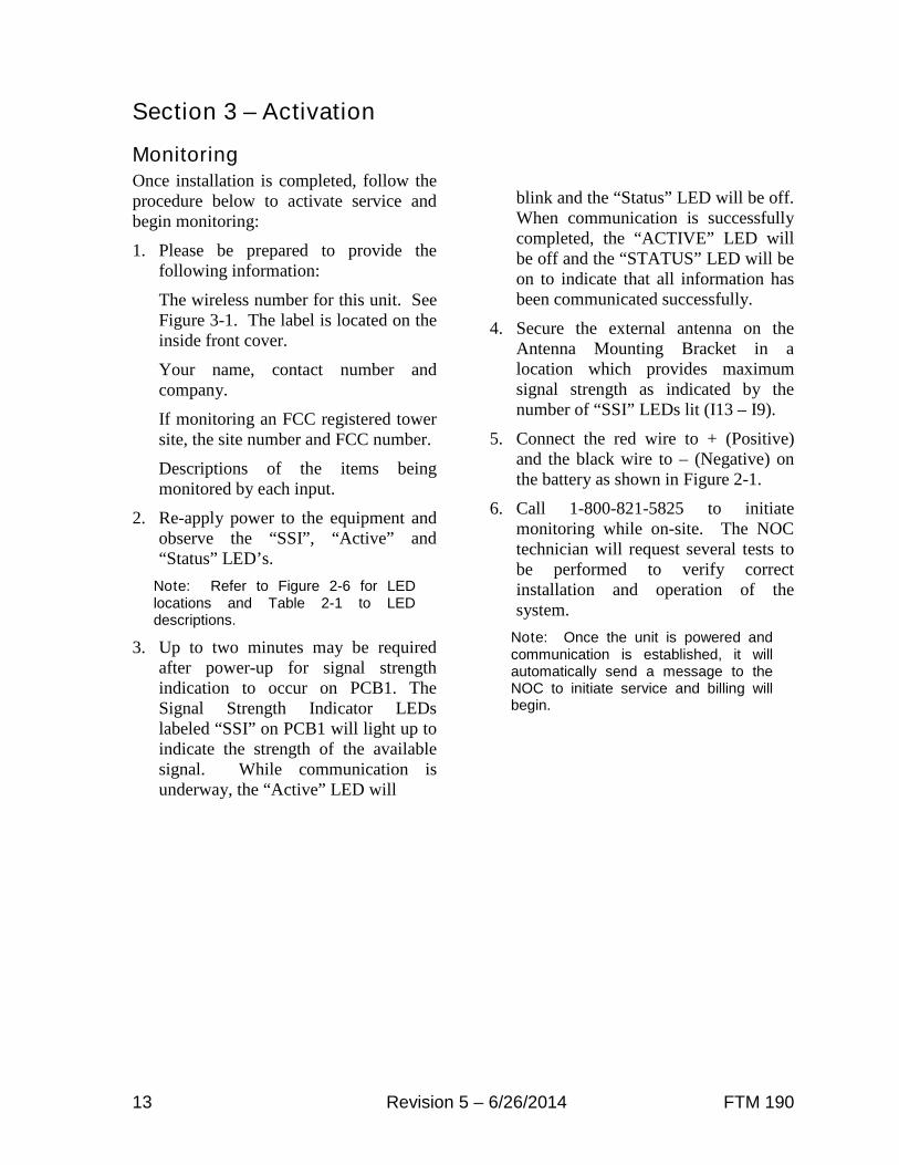
MonitoringOnce installation is completed, follow theprocedure below to activate service andbegin monitoring:
1. Please be prepared to provide thefollowing information:
The wireless number for this unit. SeeFigure 3-1. The label is located on theinside front cover.
Your name, contact number andcompany.
If monitoring an FCC registered towersite, the site number and FCC number.
Descriptions of the items beingmonitored by each input.
2. Re-apply power to the equipment andobserve the “SSI”, “Active” and“Status” LED’s.
Note: Refer to Figure 2-6 for LEDlocations and Table 2-1 to LEDdescriptions.
3. Up to two minutes may be requiredafter power-up for signal strengthindication to occur on PCB1. TheSignal Strength Indicator LEDslabeled “SSI” on PCB1 will light up toindicate the strength of the availablesignal. While communication isunderway, the “Active” LED will
blink and the “Status” LED will be off.When communication is successfullycompleted, the “ACTIVE” LED willbe off and the “STATUS” LED will beon to indicate that all information hasbeen communicated successfully.
4. Secure the external antenna on theAntenna Mounting Bracket in alocation which provides maximumsignal strength as indicated by thenumber of “SSI” LEDs lit (I13 – I9).
5. Connect the red wire to + (Positive)and the black wire to – (Negative) onthe battery as shown in Figure 2-1.
6. Call 1-800-821-5825 to initiatemonitoring while on-site. The NOCtechnician will request several tests tobe performed to verify correctinstallation and operation of thesystem.
Note: Once the unit is powered andcommunication is established, it willautomatically send a message to theNOC to initiate service and billing willbegin.

FTM 190 Revision 5 – 6/26/2014 14
Section 4 – Web Interface
Web InterfaceThe FTM 190’s Web Interface provides aconvenient way to program the system andtemporarily control mode withoutphysically accessing the unit. The abilityto perform Lighting Inspections remotelyon select Flash Technology lightingequipment connected via the RS 485interface is also provided. Additionaluseful information such as event history,cumulative runtime and the FTM 190product manual (current at firmwarerelease) can be viewed via the webinterface.
Initial SetupThe following items are required for initialaccess and setup of the system:
Laptop computer
Ethernet crossover cable
1. Set the computer’s IP address to192.168.1.15
2. Connect the crossover cable betweenthe laptop’s Ethernet port and theEthernet port (J9) located on the FTM190.
3. Open a web browser on the laptop andenter the following address on thebrowser’s address line:http://192.168.1.11
4. The web browser will display a screensimilar to the one shown to the right.
5. Locate and select the FTM 190’sConfiguration Menu located at thebottom of the window.
Note: Shown with AT&Tmodem installed. VerizonModem Status similar.

15 Revision 5 – 6/26/2014 FTM 190
Configuration MenuThe Configuration menu provides accessto all of the FTM 190’s programmablesettings. The menu is divided into thefollowing four subsections: Device,Monitoring, Network and SNMP Labels.Each menu section is discussed in thefollowing subheadings.
Note: “Cellular Modem” ConfigurationMenu option present only with AT&Tmodem installed.
Device
The Device Configuration menu, shown tothe right, provides access to configure thedry contact inputs and the relay output. Italso allows RS 485 communication andinput power monitoring to be enabled ordisabled. The following subheadingsprovide detailed information regardingconfiguration of each option in the DeviceConfiguration Menu.
Note: Once configuration is completed,any changes must be saved bypressing the “Commit Settings” button.

FTM 190 Revision 5 – 6/26/2014 16
Relay Status
The FTM 190 provides one relay outputfor control of an external device. The stateof the relay output is controlled by theconfiguration menu.
Note: Relay contacts rated at 5A 250VAC. The connected load must notexceed this limit.
Dry Contact Input Configuration
The dry contact configuration menu isdivided into two sections. The firstsection allows the alarm state of thecontact to be selected.
Note: To ensure proper alarmmonitoring, Flash Technologyrecommends monitoring contacts thatare open in an alarm condition.
The second section allows each drycontact input to be enabled or disabled.
RS 485 Alarm Configuration
If connected, RS 485 communication isautomatically detected and configured.The RS 485 communication alarm is notautomatically enabled. Enable the alarm ifa device utilizing RS 485 communicationsis connected at J5 terminals 7-9.Typically, the RS 485 alarm is disabled ifdry contact only monitoring is utilized.
Note: Currently, only Flash TechnologyFTB 3XX Medium Intensity Strobes(29038xx PCB) and FTS 36XX systemsmay be connected via RS 485. See“Tower Menu” for additional information.
Input Power Alarm Configuration
The Input AC Power alarm monitors theAC power input to the FTM190. Enablethe alarm if notification of AC powerfailure is desired.
Commit Settings
Once programming is complete, anychanges must be saved by pressing the“Commit Settings” button. Press “Cancel”to discard changes. Press the “Home”button to return to the main menu.
Reboot
Pressing the “Reboot´ button initiates anautomatic sequence that powers the FTM190 off and then on again.

17 Revision 5 – 6/26/2014 FTM 190
Monitoring
The Monitoring Configuration menu,shown to the right, provides access toconfigure the Primary and Alternatemonitoring methods. Configuration foreach method is discussed in the followingsubheadings.
Primary Monitoring Configuration
The Primary Monitoring Configurationmenu provides setup of Eagle monitoringby Cellular or Ethernet connection. TheMonitoring Method should be set to“Disable” if the system is not monitoredby Flash Technology.
The “Automatic Update Interval” isselectable from 1 to 24 hours. Use thedrop down menu to select the desiredinterval. Press the “Commit Settings”button to apply changes.
Note: The default Monitoring Method is“Cellular Eagle” when the FTM 190 issupplied with a cellular modem.
Alternate Monitoring Configuration
The Alternate Monitoring Configurationmenu provides setup of SNMP monitoringby Ethernet connection. The default for theAlternate Monitoring Method is Disabled.
The “Automatic Update Interval” isselectable from 1 to 24 hours. Use thedrop down menu to select the desiredinterval. Press the “Commit Settings”button to apply changes.

FTM 190 Revision 5 – 6/26/2014 18
Network
Local Network Configuration
The Local Network Configuration menuallows the FTM 190’s IP address to be setas Static or Dynamic. Configure asrequired for user’s network.
Cellular Modem
The Cellular Modem menu allowsselection of the SIM card as AT&T Director AT&T ROW. AT&T Direct should beselected for SIM cards bearing the AT&TLogo. AT&T ROW should be selected forall other SIM cards.
Note: “Cellular Modem” ConfigurationMenu option present only with AT&Tmodem installed.
Important! Changing SIM Card Typecould interrupt wireless communicationwith the FTM 190. The SIM Card Typeshould not be changed remotely.
SNMP Labels
The SNMP Configuration menu providesan alternative method to configure labelsfor SNMP traps associated with the FTM190.
Note: The screenshot shown above isdivided into three sections. Any changesto the labels for Customer Site ID – DryContact 8 will be shown on the WebInterface. Any changes to the labels forFTM Input AC Power – CommunicationChange will be shown on the SNMP Traponly. The label change will not be reflectedon the Web Interface. The severitycolumn is shown on the SNMP Trap only.

19 Revision 5 – 6/26/2014 FTM 190
Web Interface(36XX Lighting Controller)
When connected via RS 485, the FTM190’s Web Interface provides access toprogram, test and monitor virtually allfunctions of the connected FTS 36XXsystem. An example of the Home Menuwith the lighting system connected isshown to the right.
Tower Lighting Status
The Tower Lighting Status menu, shownto the right, provides an overview of thecurrent status and configuration of the FTS36XX system. This menu is informationalonly.
Lighting Inspection Menu
Two options are available via the Web
Interface to perform Lighting Inspections
(LI): Auto Fast LI and Manual LI. A
brief description of each LI type is
provided on-screen beside the selection.
The Results page button displays LI
progress and previous LI results.
Auto Fast LI
Once initiated, the Auto Fast LI requiresno additional input from the user. Theresults are displayed automatically uponcompletion of the Lighting Inspection.
Note: FTM 190 Dry Contact inputs notshown.

FTM 190 Revision 5 – 6/26/2014 20
Manual LI
The Manual LI tests each lightingcomponent individually in sequence. Therestore stage for each component is heldawaiting user input before advancing totest the next component. In this mode, theuser must press “Cont.” (Continue) beforethe system will restore the alarm andadvance to the next test. The results aredisplayed once all tests are completed.
Mode Override
The Force Mode Override Menu, locatedbelow the Lighting Inspection menuallows manual selection of the system’smode. System control will return toautomatic after 30 minutes.
FTS 36XX Configuration
The FTS 36XX Configuration Menu isdivided into two sections: Tower Lightingand SNMP Labels.
Tower Lighting (Configuration)
The Tower Lighting menu allowsprogramming of system type, number ofbeacons and marker tiers. A drop downmenu is provided for each option. Markermode (flashing or steady) is selected byclicking on the desired setting.
Important! The Tower Configurationmust be programmed to match theFAA designated lighting system typefor the structure.
The Tower Configuration menu alsoallows the photocell alarm (PEC Defeat)to be enabled or disabled. When enabled,the system’s 19 hour mode timer isprevented from generating a photocellalarm. This feature is particularly usefulin areas that are prone to periods of lightor darkness that would exceed the 19 hourmode timer. Press the “Commit Settings”button to apply changes.
Note: The photocell alarm is intendedto provide notification of a possiblefailure in the system. The disarmfeature should only be activated if thesystem is installed in a location prone toconditions previously described. Verifythat the photocell is installed andfunctioning correctly before enablingthis option.
21 Revision 5 – 6/26/2014 FTM 190
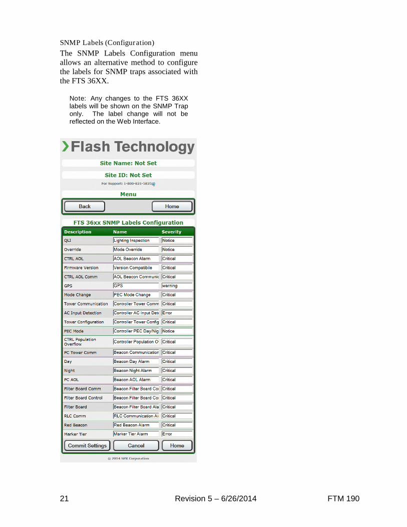
SNMP Labels (Configuration)
The SNMP Labels Configuration menuallows an alternative method to configurethe labels for SNMP traps associated withthe FTS 36XX.
Note: Any changes to the FTS 36XXlabels will be shown on the SNMP Traponly. The label change will not bereflected on the Web Interface.

FTM 190 Revision 5 – 6/26/2014 22
Web Interface(Medium Intensity Strobe 29038XX PCB)
When connected via RS 485, the FTM190’s Web Interface, shown to the right,provides access to review theconfiguration and current status of theFlash Technology Medium IntensityStrobe system (29038XX PCB).
Mode Override
The Force Mode Override Menu allowsmanual selection of the system’s mode.System control will return to automaticafter 30 minutes.

23 Revision 5 – 6/26/2014 FTM 190
Section 5 – Troubleshooting
Table 5-1 – Troubleshooting –Power
Step Check/Test/Action Action1.a Is PCB1’s AC PWR LED lit? Yes
NoGo to Step 1.gGo to Step 1.b
1.b Is AC power applied to the FTM 190?Measure at TB1 terminals L1 & N.
YesNo
Go to Step 1.cCheck power source, circuitbreaker or disconnect switch andwiring between source and FTM190.
1.c Is AC power present at the output of TB1?Measure at TB1 terminals L1F and N.
YesNo
Go to Step 1.dRemove input power at thesource. Replace fuse F1 andVR1.
1.d Is AC input power present on input of PCB2?Measure at L and N on PCB2. See Figure 2-1 forlocation.
YesNo
Go to Step 1.eCheck / repair wiring betweenTB1 and PCB2.
1.e Is PCB2’s Green “AC” LED lit?See Figure 2-1 for location.
YesNo
Go to Step 1.fReplace PCB2.
1.f Is the AC Fail Input grounded at PCB1?Measure DC Voltage between PCB1 J11 Yellowand Orange wires. Is the voltage zero volts DC?
YesNo
Replace PCB1.Check/repair wiring betweenPCB2 and PCB1.Replace PCB2
1.g Are both of PCB1’s DC Power LED’s (+3.3V,+5.0V) lit?
YesNo
Go to Step 2.aGo to Step 1.h
1.h Is PCB2’s Red “DC” LED lit?Note: Verify that the input power switch, locatedon PCB2, is in the “On” position. See Figure 2-1for LED and switch locations.
YesNo
Go to Step 1.iGo to Step 1.j
1.i Is DC voltage present on PCB1 J11?Measure at J11 DC- and DC+.
YesNo
Replace PCB1Go to Step 1.j
1.j Is PCB2’s Red “DC” LED lit when output power toPCB1 is disconnected?With the system power off, unplug connector J10 (ifinstalled) and J11 on PCB1. Apply power to thesystem.
YesNo
Go to Step 1.kReplace PCB2.
1.k Is PCB2’s Red “DC” LED lit when output power toPCB1 reconnected but J10 is not connected?Power the system down and reconnect J11.Connector J10 (if present) should remaindisconnected. Power the system on and check thestatus of the DC LED.
Yes
No
Check / repair wiring betweenJ10 and optional modem.Replace modem if necessary.Replace PCB1.

FTM 190 Revision 5 – 6/26/2014 24
Table 5-2 – Troubleshooting – Cellular Connection
Step Check/Test/Action Action2.a Is PCB1’s STATUS LED Lit? Yes
NoGo to Step 2.hTo test communication, firstconfirm that the battery isconnected and then disconnectAC Power.PCB1’s Active LED should blinkto indicate cellularcommunications is underway.PCB1’s Status LED should turnon when communication iscomplete to indicate allinformation has beencommunicated successfully.If the ACTIVE or STATUS LED’sdo not light, proceed to Step 2.b.
2.b Is the modem’s SVC LED on?SVC LED off indicates modem is not powered
YesNo
Go to Step 2.dGo to Step 2.c
2.c Is input power present to the modem?See Figure 2-1. Check 12 VDC at modemterminals 5 & 6.
YesNo
Go to Step 2.dCheck connections betweenPCB 1 and the modem. ReviewTable 5-1.
2.d Is the modem’s LAN LED lit?The LAN LED is ON if the Ethernet link betweenModem and PCB is OK
YesNo
Go to Step 2.eCheck CAT 5 cable connectionbetween modem and J9 locatedon PCB1. Replace cable ifnecessary. Replace PCB1 and /or modem if necessary. LANLED must be lit beforeproceeding to Step 2.e
2.e Is the modem’s SVC LED green?
Blinking YELLOW indicates no signalSolid YELLOW indicates low signalSolid GREEN indicates good signal
YesNo
Go to Step 2.fYellow blinking or solid indicatesa weak signal. Check theantenna and cable for damage;replace if necessary. Relocatethe antenna if no damage isfound. SVC LED must be solidyellow or green beforeproceeding to Step 2.f.
2.f Are any of PCB1’s Signal Strength Indicator (SSI)LED’s lit?See Figure 2-6 for location.The SSI LED’s will indicate the Signal Strengthapproximately 35 seconds after the antenna ismoved.
YesNo
Go to Step 2.gGo to Step 2.e
2.g Is the modem’s LNK LED lit?GREEN indicates 2G connection (1xRTT orGPRS)RED indicates 3G connection (EV-DO or HSPA)
YesNo
Go to Step 2.hNetwork, SIM or modem issue.Power the unit down. Wait five(5) minutes and power the uniton. Contact Technical Supportfor RMA problem persists.
2.h Contact the Flash Technology NOC to check if thesystem reported in correctly.

25 Revision 5 – 6/26/2014 FTM 190
Section 6 – Recommended Spare & Replaceable Parts
Customer ServiceCustomer Service: (800) 821-5825
Telephone: (615) 261-2000
Facsimile: (615) 261-2600
Shipping Address:
Flash Technology332 Nichol Mill LaneFranklin, TN 37067
Ordering PartsTo order spare or replacement parts, contact customer service at 1-800-821-5825.
Important! When removing power from the equipment, ensure that the red wire to thebattery is disconnected first. Reconnect battery after work is completed.

FTM 190 Revision 5 – 6/26/2014 26
OF
FO
N
NC NO NC NOC C
+
LOWBAT
ACFAIL
DC
AUX
AC FAIL
J11
DC POWERINPUTS
MODEMPWR
J10
12V
GND
Flash Technology
J8J9
12
V
PCB2
POWER SUPPLY(P/N 5370500)
(LOCATED UNDER PCB1)
BAT DC
L G N
AC DC
GN
D
I9I10I11I12I13SSI
I4I5I6I7I8
ACTIVESTATUSRLY CTLRS485 TXRS485 RX
I1I2I3
+3.3V+5.0VAC PWR
I14I15I16I17
IN 1IN 2IN 3IN 4
I18I19
IN 5IN 6IN 7IN 8
I20I21
+
--
+
RX TX GNDB A
A B GND NC NOCOM
DRY CONTACT INPUTSRELAY OUTRS485RS232/485RS232
J5 J6 J7
IN1 IN2 IN3 IN4 IN5 IN6 IN7 IN8RX TX GND
-- --
MODEM
ATT (P/N 5905205)
GND
OPTIONINSTALL AREA
PCB3PROCESSOR
VERIZON (P/N 5905204)
Figure 6-1 – Component Locations
27 Revision 5 – 6/26/2014 FTM 190
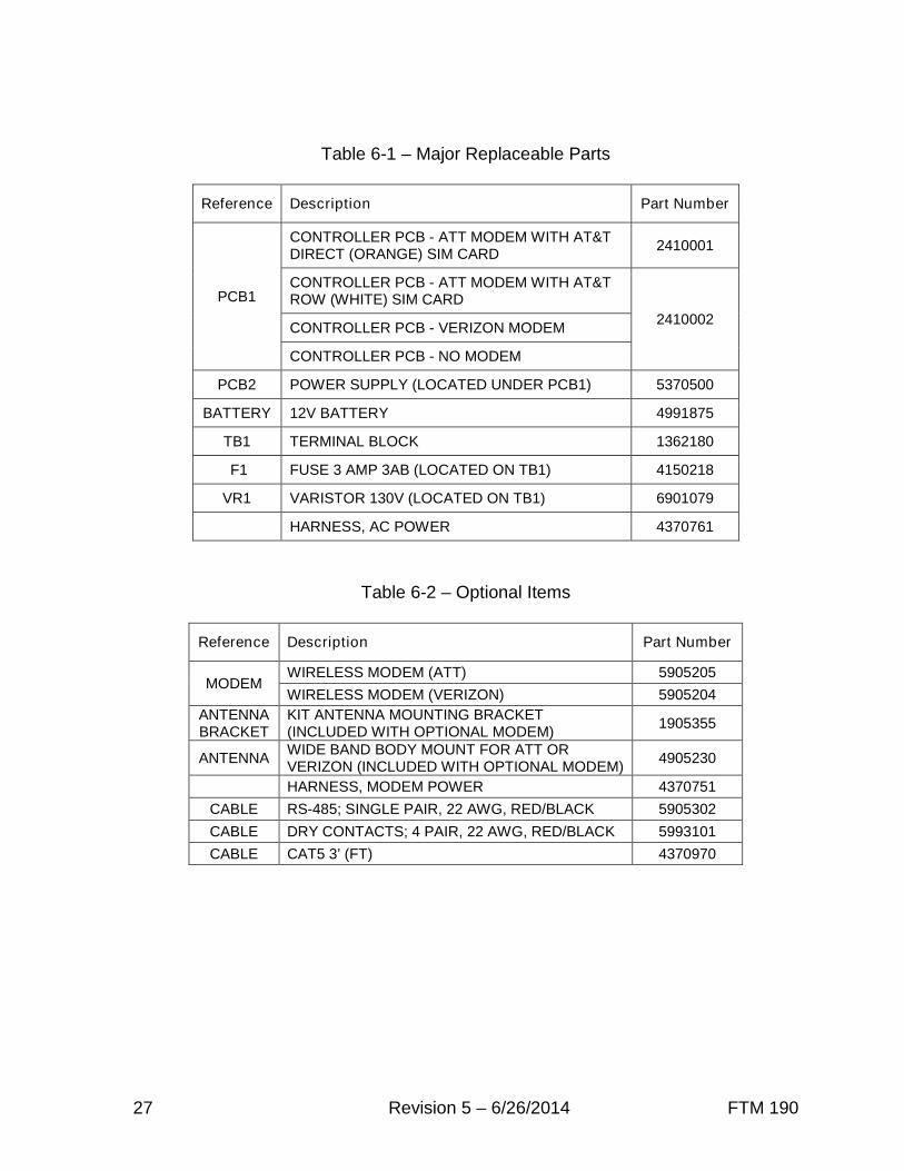
Table 6-1 – Major Replaceable Parts
Reference Description Part Number
PCB1
CONTROLLER PCB - ATT MODEM WITH AT&TDIRECT (ORANGE) SIM CARD
2410001
CONTROLLER PCB - ATT MODEM WITH AT&TROW (WHITE) SIM CARD
2410002CONTROLLER PCB - VERIZON MODEM
CONTROLLER PCB - NO MODEM
PCB2 POWER SUPPLY (LOCATED UNDER PCB1) 5370500
BATTERY 12V BATTERY 4991875
TB1 TERMINAL BLOCK 1362180
F1 FUSE 3 AMP 3AB (LOCATED ON TB1) 4150218
VR1 VARISTOR 130V (LOCATED ON TB1) 6901079
HARNESS, AC POWER 4370761
Table 6-2 – Optional Items
Reference Description Part Number
MODEMWIRELESS MODEM (ATT) 5905205
WIRELESS MODEM (VERIZON) 5905204
ANTENNABRACKET
KIT ANTENNA MOUNTING BRACKET(INCLUDED WITH OPTIONAL MODEM)
1905355
ANTENNAWIDE BAND BODY MOUNT FOR ATT ORVERIZON (INCLUDED WITH OPTIONAL MODEM)
4905230
HARNESS, MODEM POWER 4370751
CABLE RS-485; SINGLE PAIR, 22 AWG, RED/BLACK 5905302
CABLE DRY CONTACTS; 4 PAIR, 22 AWG, RED/BLACK 5993101
CABLE CAT5 3’ (FT) 4370970

RMA Policy Revision 2014A
Return Material Authorization (RMA) Policy
IF A PRODUCT PURCHASED FROM FLASH TECHNOLOGY MUST BE RETURNED FOR ANYREASON (SUBJECT TO THE WARRANTY POLICY), PLEASE FOLLOW THE PROCEDURE BELOW:
Note: An RMA number must be requested from Flash Technology prior to shipment of anyproduct. No returned product will be processed without an RMA number. This number will be theonly reference necessary for returning and obtaining information on the product’s progress.
1. To initiate an RMA: Call Flash Technology’s National Operations Center (NOC) at (800-821-
5825) to receive technical assistance and a Service Notification number. The following
information is required before a Service Notification number can be generated:
• Site Name/Number / FCC Registration number/ Call Letters or Airport Designator
• Site Owner (provide all that apply – owner, agent or subcontractor)
• Contractor Name
• Contractor Company
• Point of Contact Information: Name, Phone Number, Email Address, Fax Number and Cell Phone
(or alternate phone number)
• Product’s Serial Number
• Product’s Model Number or part number
• Service Notification Number (if previously given)
• Reason for call, with a full description of the reported issue
2. The Service Notification number will then serve as a precursor to receiving an RMA number if
it is determined that the product or equipment should be returned. To expedite the RMA
process please provide:
• Return shipping method• Shipping Address• Bill to Address• Any additional information to assist in resolving the issue or problem
3. Product within the Warranty Time Period
a. If to be returned for repair;
• RMA # is generated
• Once product is received and diagnosed;
• Covered under warranty – product is repaired or replaced
• Not covered under warranty – quote is sent to the customer for a bench fee of
$350 plus parts for repair
• If the customer does not want the product repaired, a $50 test fee is
charged before being returned
b. If advance replacement;
• Purchase order may be required before the advance replacement order is created
• RMA # is generated and the advance replacement order is created
• Once product is received and diagnosed;
• Covered under warranty – credit given back if PO received
• Not covered under warranty – credit will not be applied to PO
• Flash Technology has sole discretion in determining warranty claims. Flash Technology
reserves the right to invoice for parts advanced if the associated failed parts are not
returned within 15 days of issue or if product received is diagnosed to be non-warranty.

Revision 2014A RMA Policy
• Advance replacements will be shipped ground unless the customer provides alternative
shipping methods.
4. Product outside the Warranty Time Period
a. For Xenon System board repair; a purchase order is required at time of request for a RMA # for a
standard $350 repair bench fee
• RMA # is generated with the PO attached
• If the board is deemed non-repairable after diagnosis, the customer is notified. If the
customer purchases a new board, the repair bench fee is waived. If the customer does
not buy a new board, a $50 test fee is charged before being returned or scrapped.
b. For all other products; no purchase order is required to return the product for diagnosis
• RMA # is generated
• Once product is diagnosed, quote is sent to the customer for a bench fee of $350 plus
parts for repair
• Once the purchase order is received, the product will be repaired and returned
• If the customer does not want the product repaired, a $50 test fee is charged
before being returned or scrapped.
5. After receiving the Flash Technology RMA number, please adhere to the following packaging
guidelines:
• All returned products should be packaged in a way to prevent damage in transit. Adequate packingshould be provided taking into account the method of shipment.Note: Flash Technology will not be responsible for damaged items if product is not returned inappropriate packaging.
6. All packages should clearly display the RMA number on the outside of all RMA shipping
containers. RMA products (exact items and quantity) should be returned to:
Flash TechnologyAttn: RMA #XXX332 Nichol Mill LaneFranklin, TN 37067
7. All RMA numbers:
• Are valid for 30 days. Products received after 30 days may result in extra screening and delays.• Must have all required information provided before an RMA number is assigned.