flash link updater 2 - fortin bypass · addendumconfigura wiring suggested tion - addenda - schÉma...
TRANSCRIPT

ADDENDUM - SUGGESTED WIRING CONFIGURATION ADDENDA - SCHÉMA DE BRANCHEMENT SUGGÉRÉ
ALL REV.: 20160330
FLASH LINK UPDATER 2 FLASH LINK UPDATER 2
1XMicrosoft Windows Computer &Internet connection
Ordinateur Microsoft Windows & connection Internet
THAR-CHR6 && 300 / CHARGER / JOURNEY
Parts required (Not included) Pièce(s) requise(s) (Non incluse(s))
1X Fuse1X Diode1X T-harness THAR-CHR6
1X Fusible1X Diode1X THAR-CHR6 t-harnais
Vehicle functions supported in this diagram (functional if equipped) | Fonctions du véhicule supportées dans ce diagramme (fonctionnelles si équipé)
VEHICLEVEHICULES
YEARS ANNÉES Im
mob
ilize
r byp
ass
Lock
Unl
ock
Arm
Dis
arm
Hat
ch (o
pen)
RA
P D
isab
le
Tach
omet
er
Doo
r Sta
tus
Trun
k S
tatu
s
Hoo
d S
tatu
s
Han
d-B
rake
Sta
tus
Foot
-Bra
ke S
tatu
s
OEM
Rem
ote
mon
itorin
g
CHRYSLER300-300C Push-to-Start 2011-2015 • • • • • • • • • • • • • •DODGECharger Push-to-Start 2011-2015 • • • • • • • • • • • • • •Journey Push-to-Start 2011-2016 • • • • • • • • • • • • • •
Guide # 12131
A B C D
FE
G
BCM, Behind glove box, Right sideBCM, Derrière le coffre à gant, Côté Droite.
Copyright © 2012, Fortin Auto Radio Inc
Clips
ConnectorConnecteur
F
Copyright © 2012, Fortin Auto Radio Inc
F(-)Door Pin
Pull the clips to release the cover of the connector.Soulevez les clips pour sortir le couvert du connecteur.
At Parking-Light switchAu commutateur des lumières de stationnement
Parking Lights
Harness in driverkick panelHarnais dans le panneau latéral côté chauffeur
Harness in passengerkick panelHarnais dans le panneau latéral côté passager
JOURNEY:
300, CHARGER:
OBD-II connectorConnecteur OBD-II
1
9 10
2 3 4
11 12
CAN HIGH Pin 6
CAN LOW Pin 14
7 85 61314 15 16
PUSHSTART
(+) IGNITION
HARDWARE VERSIONVERSION MATÉRIELLE
FIRMWARE VERSIONVERSION LOGICIELLE This manual may change without notice.
www.fortinbypass.com for latest version. Ce Guide peut faire l’objet de changement
sans préavis. www.fortinbypass.com pour la récente version.
MINIMUM 6 74.[24]CHRYSLER/DODGE/JEEP/MITSUBISHI MINIMUM
A B C D
FE
G
BCM, Behind glove box, Right sideBCM, Derrière le coffre à gant, Côté Droite.
Copyright © 2012, Fortin Auto Radio Inc
Clips
ConnectorConnecteur
F
Copyright © 2012, Fortin Auto Radio Inc
F(-)Door Pin
Pull the clips to release the cover of the connector.Soulevez les clips pour sortir le couvert du connecteur.
At Parking-Light switchAu commutateur des lumières de stationnement
Parking Lights
Harness in driverkick panelHarnais dans le panneau latéral côté chauffeur
Harness in passengerkick panelHarnais dans le panneau latéral côté passager
JOURNEY:
300, CHARGER:
OBD-II connectorConnecteur OBD-II
1
9 10
2 3 4
11 12
CAN HIGH Pin 6
CAN LOW Pin 14
7 85 61314 15 16
PUSHSTART
(+) IGNITION
Back of Push-to-Start ButtonDos du Bouton poussoir
(+) 12 VOLTS
COPYRIGHT © 2012,FORTIN AUTO RADIO INC
GROUND
DATA (+) START/STOP SIGNAL
Page 1 / 8

This guide may change without notice. See www.fortin.ca for latest version.Ce guide peut faire l’objet de changement sans préavis. Voir www.fortin.ca pour la récente version.
NOTES
NOTES
Hood Statusfunctional if equipped with a factory hood switch. fonctionnel si équipé d’un commutateur de capot d’origine.
NOTES 12V BATTERY | 12V BATTERIE
ATTENTION THE T-HARNESS CURRENT IS LIMITED AT 10 AMP MAXIMUM.
If a parking lights (+) wire is use : they require more than 10Amp. Connect the remote-starter’s power directly to the vehicles battery with the appropriate fuse.
Some remote starters can not be powered through Data-Link. In these cases connect the remote starter’s fused 12V power wire directly to the T-Harness.
ATTENTION LE COURANT DU 12V PROVENANT DU HARNAIS-EN-T EST LIMITÉ À 10 AMPÈRES MAXIMUM.
Si le fil des lumières de stationnement (+) est utilisé: il requière plus de 10 Ampères, branchez le 12V du démarreur à distance directement à la batterie du véhicule avec le fusible approprié.
Certains démarreurs à distance NE peuvent PAS être allimentés par le Data-Link. Dans ce cas, branchez le 12V (avec fusible) du démarreur à distance directement au harnais-en-T.
Page 2 / 8

This guide may change without notice. See www.fortin.ca for latest version.Ce guide peut faire l’objet de changement sans préavis. Voir www.fortin.ca pour la récente version.
WIRING CONNECTION | GUIDE DE BRANCHEMENTS
Y����� In A1P����� In A2
P�����/W���� In A3G���� Out A4W���� Out A5
O����� In A6O�����/B���� In A7
D�.B��� In A8R��/B��� In A9
L�.B���/B���� A10B���� Out A11P��� Out A12
Y�����/B���� In A13B����/W���� Out A14
P���/B���� Out A15P�����/Y����� A16G����/W���� A17
G����/R�� A18W����/B���� A19
L�.B��� A20
C5 B���� C4 G���/B���� C3 G��� C2 O�����/B���� C1 O�����/G����
D6 W����/R�� D5 W����/B��� D4 W����/G���� D3 Y�����/R�� D2 Y�����/B��� D1 Y�����/G����
A C
D
O�����/G����O�����/B����
B����
W����/B����
G����/W����
O�����/B���� InO����� In
THAR-CHR6
Lt.Blue/BlackBleu/Noir
T-HarnessParking Lights White/Brown Feux de stationnement Blanc/Brun
A18Door PinPurpleMauve
A15
A B C D
FE
G
F
RAP
Back ViewBlack connectorVue de dosConnecteur Noir
BCM, Behind glove box,Right sideBCM, Derrière le coffre à gant, Côté Droite.
At Parking-Light switchAu commutateur des lumières de stationnementBack View, Black connectorVue de dos, Connecteur Noir
Harness indriver kick panel Harnais dans lepanneau latéralcôté chauffeur
Harness in passenger kick panelHarnais dans le panneau latéral côté passager
JOURNEY: 300, CHARGER:
Locate the ignition wire by testing the voltage with a multimeter: Ignition OFF : 0 VDC Ignition ON : ~9 VDC
Trouvez le fil d'ignition en testant avec un multimetre: Ignition éteinte : 0V Igniton allumée : ~9V
(+) Ignition Pink/WhiteRose/Blanc
(~) CANHIGHPin 6
BrownBrun
C4
1
9 10
2 3 4 5 7 8
11 12 13 14 15 16
6
14
66
C3(~) CAN
LOWPin 14YellowJaune
OBD-II connectorFront viewConnecteur OBD-IIVue de face
A1
B
Hand Brake
TachometerFoot Brake
Trunk Release
Door StatusTrunk Status
Unlock/DisarmLock/ArmIgnition
Ground While Running
CAN HIGHCAN LOW
(-)
(-)(-)(-)(-)
(+)
(-)(-)
(+/-)(+)
Starter(+)
(+) Parking Light
5Amp Fuse
RAP(-)
B
START
PARKING LIGHT
WHILE RUNNING
LOCK/ARMUNLOCK/DISARMDOOR STATUS TRUNK STATUS
FOOT BRAKETACHOMETERTRUNK RELEASEHAND BRAKE
12V BATTERYGround | Masse
(-)
(-)(-)(-)(-)
(+)(+/-)(-)(-) IN RS10
OUT RS11IN RS12 IN RS13
IN RS14IN RS15
OUT RS16OUT RS17
OUT RS18 RS8 OUT
RS4 OUT
RS2 IN(-)(+)
(+)
(+)
IGNITION1RS7 OUT (+)
RS1
A14A13A12A11
A5A4A3A2
A8
A1
A9
A16
ALWAYS REQUIREDTOUJOURS REQUIS
NOT REQUIRED WITH DATALINKNON REQUIS EN DATA-LINK
WITHOUT DATA-LINK:SANS DATA-LINK:
Cut | Coupez RedBlack
BlueWhite
B4B3B2B1
Cut | Coupez
BlackRed 12V BATTERY
GroundB4B3
T-Harness
PUSHSTART
Lt.BlueBleu Pâle
6 PIN RED CONN.
T-Harness
T-Harness
T-Harness Data-Link
4 PIN CONN.
MUX Parking Light
SEE | VOIRNOTE PAGE 2
Direct connectionBranchement directe
REMOTESTARTER
DÉMARREURÀ DISTANCE
WITH | AVEC DATA-LINK:
WITH | AVEC D2D:OUOR
D
D6
D5D4D3
D1
D2
1A Diode
Page 3 / 8
This guide may change without notice. See www.fortin.ca for latest version.Ce guide peut faire l’objet de changement sans préavis. Voir www.fortin.ca pour la récente version.
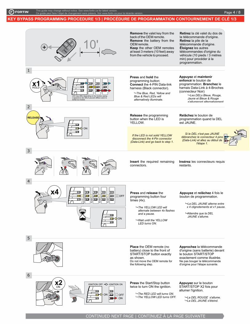
KEY BYPASS PROGRAMMING PROCEDURE 1/3 | PROCÉDURE DE PROGRAMMATION CONTOURNEMENT DE CLÉ 1/3
RELEASE
KIA RIO - PUSH-TO-START
®This Guide may change without notice. www.ifar.ca for latest version. Ce Guide peut faire l'objet de changement sans préavis. www.ifar.ca pour la récente version. Page 5 / 8
PROGRAMMING PROCEDURE 1/3 | PROCÉDURE DE PROGRAMMATION 1/3
x4
Remove the valet key from the back of the OEM remote.Remove the battery from the OEM remote.Keep the other OEM remotes at least 3 meters (10 feet) away from the vehicle to proceed.
10'+
Release the programming button when the LED is YELLOW.
Si le DEL n'est pas JAUNE débranchez le connecteur 4 pins (Data-Link) et allez au début de
l'étape 1.
ON
Insert the required remaining connectors.
FLA
SH
FLA
SH
FLA
SH
ON
2
3
4
Place the OEM remote (no battery) close to the front of START/STOP button exactly as shown. Do not move the OEM remote for the following step.
CONTINUED NEXT PAGE | CONTINUEZ À LA PAGE SUIVANTE
OFFPress and release the programming button four times (4x).
�
�
The YELLOW LED will alternate between 4x flashes and a pause.
until the YELLOW LED turns ON.
Wait
OFFON
ON
5
Press the Start/Stop button twice to turn ON the ignition.
� The RED LED will turns ON. � The YELLOW LED turns OFF.
6
PANIC
FLA
SH
PAN
ICPA
NIC
x2ON
IGNITION OFF IGNITION ON
Retirez la clé valet du dos de la télécommande d'origine.Retirez la pile de la télécommande d'origine.Éloignez les autres télécommandes d'origine du véhicule (10 pieds / 3 mètres min) pour procéder à la programmation.
Relâchez le bouton de programmation quand la DEL est JAUNE.
If the LED is not solid YELLOW disconnect the 4-Pin connector
(Data-Link) and go back to step 1.
Insérez les connecteurs requis restants.
Approchez la télécommande d'origine (sans batterie) devant le bouton START/STOP exactement comme illustrée. Ne pas bouger la télécommande d'origine pour l'étape suivante.
Attendre
Appuyez et relâchez 4 fois le bouton de programmation.
�
�
La DEL JAUNE alterne entre x 4 clignotements et x1 pause.
que la DEL JAUNE s'allume.
Appuyez sur le bouton START/STOP X2 fois pour allumer l'ignition.
� La DEL ROUGE s'allume. � La DEL JAUNE s'éteind.
1
CETTE PROGRAMMATION EST POUR LES DODGE RAM PTS 2013DODGE RAM PTS+THARCHR5 2013
Press and hold the programming button:Connect the 4-PIN Data-link harness (Black connector).
� The Blue, Red, Yellow and Blue & Red LEDs will alternatively illuminate.
Appuyez et maintenir enfoncé le bouton de programmation: Branchez le harnais Data-Link à 4-Broches (connecteur Noir)
� Les DELs Bleue, Rouge, Jaune et Bleue & Rouge s'allumeront alternativement.
x1HOLD
LED may differ depending on the module casing.L’apparence des DELS peuvent différer selon le boîtier du module.
Page 4 / 8

This guide may change without notice. See www.fortin.ca for latest version.Ce guide peut faire l’objet de changement sans préavis. Voir www.fortin.ca pour la récente version.
KEY BYPASS PROGRAMMING PROCEDURE 2/3 | PROCÉDURE DE PROGRAMMATION CONTOURNEMENT DE CLÉ 2/3PROGRAMMING PROCEDURE 2/3 | PROCÉDURE DE PROGRAMMATION 2/3
8
9
11
12
Place the OEM remote (no battery) close to the front of START/STOP button as shown.
Do not move the OEM remote for the following step.
OFF
ON
ON
Press and release the START/STOP button once to turn ON the ACCESORY.
PAN
ICPA
NIC
x1ACC
Press and release the START/STOP button once to shut off the ignition.
OFF
x1
FLASHRAPIDLY
10
x1ON Press and release
START/STOP button once to turn ON the ignition.
Reinsert the battery in the OEM remote.
Réinsérez la pile dans la télécommande d'origine.
+PANIC
13
UNLOCK
PANIC
Unlock the doors with the OEM remote.
FLASHSLOWLY
cette partie de la config. est parreille a celle dans les NISSAN CHRYSLER
SUZUKI KIZASHI
7
Press and release the START/STOP button once to shut off the ignition.
OFF
x1
CONTINUED NEXT PAGE | CONTINUEZ À LA PAGE SUIVANTE
ON
ON
FLASHRAPIDLY
IGNITION OFF ACCESORY ON
ON
ACCESORY ON IGNITION ON
OFF
IGNITION ON
Appuyez et relâchez le bouton START/STOP pour éteindre l'ignition.
Approchez la télécommande d'origine (sans batterie) devant le bouton START/STOP comme illustrée. Ne pas bouger la télécommande d'origine pour l'étape suivante.
Appuyez et relâchez le bouton START/STOP pour allumer l'ACCESSOIRE.
Appuyez et relâchez le bouton START/STOP pour allumer l'ignition.
� The RED and BLUE LED will turns ON.
� Wait for The RED LED to turns OFF
� BLUE LED remains solide.
� La DEL ROUGE et BLEU s'allument.
� Attendre que La DEL ROUGE s'éteigne
� La DEL BLEUE reste allumée solide.
� The BLUE LED continues to flash rapidly.
� La DEL BLEU continue de clignoter rapidement.
� Wait until the BLUE LED flash rapidly.
� Attendre que la DEL BLEU clignote rapidement.
Appuyez et relâchez 1 fois sur le bouton START/STOP pour éteindre l'ignition.
Déverrouillez les portes avec la télécommande d'origine.
� Wait until the BLUE flash slowly.
� Attendre que la DEL BLEU clignote lentement.
Page 5 / 8

This guide may change without notice. See www.fortin.ca for latest version.Ce guide peut faire l’objet de changement sans préavis. Voir www.fortin.ca pour la récente version.
KEY BYPASS PROGRAMMING PROCEDURE 3/3 | PROCÉDURE DE PROGRAMMATION CONTOURNEMENT DE CLÉ 3/3
EVO-ALL
Disconnect the Data-Link (4-pins) connector and afterall the remaining connectors.
Débranchez le connecteur Data-Link (4-pins) et ensuitetous les connecteurs restants.
REMOTE STARTER / ALARM VERIFICATION PROCEDURE | PROCÉDURE DE VÉRIFICATION DU DÉMARREUR À DISTANCE / ALARMETest the remote starter. Remote start the vehicle.Testez le démarreur à distance. Démarrez le véhicule à distance.
The module is now programmed.Le module est programmé.
FLASH LINKUPDATER 2
FLASH LINKUPDATER 2
FLASH LINK MANAGERSOFTWARE | PROGRAMME
Microsoft Windows Computer with Internet connectionOrdinateur Microsoft Windows avec connection Internet
Parts required (not included)Pièces requises (non incluses)
Connect the module to the FLASH LINK UPDATER 2 and visit the DCryptor menu in the Flash-Link Manager.
Branchez le module au FLASH LINK UPDATER 2et visitez le menu DCryptor dans le Flash-Link Manager.
AFTER DCRYPTOR PROGRAMMING COMPLETEDGo back to the vehicle and reconnect the 4-Pin (Data-Link) connector and after, all the remaining connector.
APRÈS LA PROCÉDURE DE PROGRAMMATION DCRYPTOR COMPLETÉE : retournez au véhicule etrebranchez le connecteur 4-pins (Data-Link) et après, tous les connecteurs du EVO-ALL.
EVO-ALL
14
15
16
VEHICLE EQUIPPED WITH OEM ALARM | VÉHICULE ÉQUIPÉS D’UNE ALARME D’ORIGINE
Page 6 / 8
This guide may change without notice. See www.fortin.ca for latest version.Ce guide peut faire l’objet de changement sans préavis. Voir www.fortin.ca pour la récente version.
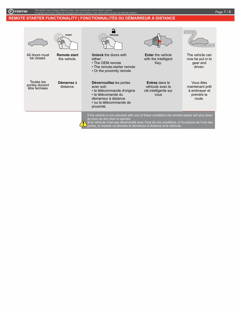
REMOTE STARTER FUNCTIONALITY | FONCTIONNALITÉS DU DÉMARREUR À DISTANCE
PROGRAMMING PROCEDURE 3/3 | PROCÉDURE DE PROGRAMMATION 3/3
14
EVO-ALL
EVO-ALL
FLASH LINKUPDATER 2
ALLE O ALL
FLASH LINKUPDATER 2
FLASH LINK MANAGERSOFTWARE | PROGRAMME
Microsoft Windows Computer with Internet connectionOrdinateur Microsoft Windows avec connection Internet
Parts required (not included)Pièces requises (non incluses)
16
15
REMOTE STARTER / ALARM VERIFICATION PROCEDURE | PROCÉDURE DE VÉRIFICATION DU DÉMARREUR À DISTANCE / ALARMETest the remote starter. Remote start the vehicle.Testez le démarreur à distance. Démarrez le véhicule à distance.
The module is now programmed.Le module est programmé.
Reconnect the 4-Pin (Data-Link) connector and after all the remaining connector.
Rebranchez le connecteur 4-pins (Data-Link) et après tous les connecteurs du EVO-ALL.
Connect the module to the FLASH LINK UPDATER 2 and visit the DCryptor menu in the Flash-Link Manager .
Branchez le module au FLASH LINK UPDATER 2et visitez le menu DCryptor dans le Flash-Link Manager.
Disconnect all EVO-ALL connectors.
Débranchez tous les connecteurs du EVO-ALL.
If the vehicle is not unlocked with one of these conditions the remote-starter will shut down as soon as any door is opened.Si le véhicule n'est pas déverrouillé avec l'une de ces conditions, à l'ouverture de l'une des portes, le module va éteindre le démarreur à distance et le véhicule.
Remote start the vehicle.
Démarrez à distance.
START
All doors must be closed.
Toutes les portes doivent être fermées
UNLOCK
Enter the vehicle with the Intelligent
Key.
Entrez dans le véhicule avec la
clé intelligente sur vous
The vehicle can now be put in to
gear and driven.
Vous êtes maintenant prêt à embrayer et
prendre la route.
Unlock the doors with either: • The OEM remote • The remote-starter remote• Or the proximity remote
Déverrouillez les portes avec soit: • la télécommande d'origine• la télécomande du démarreur à distance• ou la télécommande de proximté.
FONCTIONNALITÉ DU DÉMARREUR À DISTANCEREMOTE STARTER FUNCTIONNALITY
EVO-ALL
Page 7 / 8

Service No : 000 102 04 2536
Date: xx-xx
INTERFACE MODULE
Made in CanadaPATENTS PENDING US: 2007-228827-A1
www.fortinbypass.com
HARDWARE VERSION FIRMWARE VERSION
Module label | Étiquette sur le module
Notice: Updated Firmware and Installation GuidesUpdated fi rmware and installation guides are posted on our web site on a regular basis. We recommend that you update this module to the latest fi rmware and download the latest installation guide(s) prior to the installation of this product.
Notice: Mise à jour microprogramme et Guides d’installationsDes mises à jour du Firmware (microprogramme) et des guides d’installation sont mis en ligne régulièrement. Vérifi ez que vous avez bien la dernière version logiciel et le dernier guide d’installation avant l’installation de ce produit.
WARNINGThe information on this sheet is provided on an (as is) basis with no representation or warranty of accuracy whatsoever. It is the sole responsibility of the installer to check and verify any circuit before connecting to it. Only a computer safe logic probe or digital multimeter should be used. FORTIN ELECTRONIC SYSTEMS assumes absolutely no liability or responsibility whatsoever pertaining to the accuracy or currency of the information supplied. The installation in every case is the sole responsibility of the installer performing the work and FORTIN ELECTRONIC SYSTEMS assumes no liability or responsibility whatsoever resulting from any type of installation, whether performed properly, improperly or any other way. Neither the manufacturer or distributor of this module is responsible of damages of any kind indirectly or directly caused by this module, except for the replacement of this module in case of manufacturing defects. This module must be installed by qualifi ed technician. The information supplied is a guide only. This instruction guide may change without notice. Visit www.fortinbypass.com to get the latest version.
MISE EN GARDE L’information de ce guide est fournie sur la base de représentation (telle quelle) sans aucune garantie de précision et d’exactitude. Il est de la seule responsabilité de l’installateur de vérifi er tous les fi ls et circuits avant d’effectuer les connexions. Seuls une sonde logique ou un multimètre digital doivent être utilisés. FORTIN SYSTÈMES ÉLECTRONIQUES n’assume aucune responsabilité de l’exactitude de l’information fournie. L’installation (dans chaque cas) est la responsabilité de l’installateur effectuant le travail. FORTIN SYSTÈMES ÉLECTRONIQUES n’assume aucune responsabilité suite à l’installation, que celle-ci soit bonne, mauvaise ou de n’importe autre type. Ni le manufacturier, ni le distributeur ne se considèrent responsables des dommages causés ou ayant pu être causés, indirectement ou directement, par ce module, excepté le remplacement de ce module en cas de défectuosité de fabrication. Ce module doit être installé par un technicien qualifi é. L’information fournie dans ce guide est une suggestion. Ce guide d’instruction peut faire l’objet de changement sans préavis. Consultez le www.fortinbypass.com pour voir la plus récente version.
Copyright © 2006-2014, FORTIN AUTO RADIO INC ALL RIGHTS RESERVED PATENT PENDING
TECH SUPPORTTél: 514-255-HELP (4357) 1-877-336-7797
ADDENDUM GUIDEWEB UPDATE | MISE À JOUR INTERNET
www.fortinbypass.com
ALL
EVO-ALL
Page 8 / 8