flash 4 en
TRANSCRIPT

focflash-light
fibre optical components GmbH
March 2011
At the speed of light into the future.

The ideas and commitments from yesterday are of no use for the business of tomorrow. Thissimple truth painfully applies to the FTTx situation in Germany. According to statistics fromthe FTTH Council less than 200,000 households are directly connected to the fibre-optical
network, the equipment is generally obsolete and investors do not have long-term plans. The onlysustainable aspect of this situation is the damage profile for the business location of Germany alsoin terms of the quality of life.
But Europe also has ground-breaking examples, such as the I5 concept of Portugal Telecom, theWDM-PON for 1.2 Gbps in the development of Nokia Siemens Networks, or Altibox, the Norwe-gian Internet provider, which builds its business model on customer satisfaction and developsand offers new products. Thus the company records sales of about 100$ per satisfied customer.These exemplary steps made by players in the FTTx arena here in Europe required new ideas andthe courage to work for their consistent realisation.
Our current issue shows examples of stakeholders in the field of broadband development inGermany. Particular attention is attached to the efficient operation of such networks, which is theprecondition for customer satisfaction and trust in new, network-based services. Here, too, newtechnical monitoring procedures are required. The future will not be shaped by reducing the offer,but by understanding the needs of the customers and by their practical implementation and furtherdevelopment to provide new products. We are looking forward to this dialogue with you.
Christian Kutza, General Manager
Editorial
Contents3 FOC sales strengthens its customers support
4 Communities take charge in the interest of their citizens
and businesses
8 New methods for monitoring FTTx networks
11 Compatibility of E-2000® connectors according
to IEC 61755-1 (Grade A)
14 FOC workshop talks 2011
15 Fibre-optic joint seminars
focflash-light
Phot
o: S
teph
anie
Eiß
rig
3
Three new colleagues to support our customers from Janua-ry. Stefan Nier is the new Head of Sales. Stefan is born inHamburg, in the north of Germany, and has been active in
the IT and telecommunications sector for more than 20 years.Following his training to become an industrial business man -agement assistant Stefan pursued his career in the field of dis-tribution. Since 1997 he has held leading positions at variousICT companies in the areas of sales, business development andgeneral management. In the past five years Stefan has been re -s ponsible for the installation and operation of telecommunica-tion networks in Slovakia and the Ukraine. He worked for Tel -ecom, Nortel Networks, DeTeWe, Colt Telecom, Versatel andSwiss com. After his return to Germany Stefan assumed respon-sibility as Head of Sales at FOC in January 2011.
Michael Riecke, our new sales representative for the western re-gion of Germany, has long years of experience in communicationsengineering. As a qualified communications engineer he firstheld several positions in the fields of service, training and ap-proval at Danish and Japanese mobile radio manufacturers. Formore than 20 years Michael has been active in optical communi-cations engineering. First at the instrument manufacturer An-ritsu where he was responsible for high-speed transmissiontechnologies up to 40Gbps. Then he went to Rhode & Schwarzand supported the EXFO measurement instruments at the salesoffices in Cologne.
Another station in his career was his change to Sunrise-TelecomGermany. There Michael was Customer Care Manager and KeyAccount Manager and supported not only the key accounts suchas Deutsche Telekom and Vodafone but also a number of region-al network operators and network element manufacturers. Forhis new activity at FOC GmbH in the sales area of Western Ger-many Michael benefits from his comprehensive knowledge gain-ed in optical communications engineering.
In the south of Germany Frank Sommerfeld will be at your dis-posal. Frank strengthens our office in Stuttgart as Head of theBranch Office. He will both intensify and expand our businessrelations with existing customers in the Southern German region,in Austria and Switzerland, and be the main coordinator of oursales activities in the international arena.Within this frameworkthe successful expansion of our location in the Stuttgart regionwill be another aim. Prior to his start at FOC Frank was active inleading positions in international sales and business develop-ment in the field of telecommunications.
This included long-term stays in Arabia and Asia, where heacquired cross-functional leadership skills in the telecommuni-
cations sector and comprehensive global business practice. Professional experience: · For more than 15 years active in the telecommunications in-
dustry · Director Sales & Business Development at leading telecom-
munications suppliers and fuel cell manufacturers – EMEA &South America
· General Manager for processor technologies of the companySiegle und Epple - Europe, UAE & Asia
· Manager Engineering at Saudi Telecom · Project Manager at Alcatel/SEL AG – Europe & Asia
For the northern region Tilo Kuehnel continues to be your usu-al contact. Tilo Kuehnel is a qualified communications engineer.In the mid-80s he also studied optical communications engi-neer ing. In his career he has gained 30 years of market and tech-no l-ogy know-how on the German market.His competences:· Advising the customer on the selection of available technolo-
gies focussing on future migration scenarios · Product development (specifications) · Resulting from the above: business development/key account
management (Deutsche Telekom, municipal utility compa-nies, special-purpose associations)
· Analysis / inventory taking of existing infrastructures · Network planning and project work · Development of business models and operator concepts · Preparation of migration strategies based on existing infra-
structures · Determination of requirements and cost estimation · Support of strategy concepts up to commissioning · Preparation of operator concepts His professional history:· DeTeWe AG & Co. in Berlin: project planning, network plan-
ning, network product management, strategic marketing forpublic telecom networks
· T-Systems: project manager of strategic planning for accessnetworks
· DeTeWe: UMS platform project manager· Arthur D. Little/TIMES2C AG in Berlin: senior consultant tele-
com networks and services· exper-MEDIA GbR: managing director Technology/Strategy· DIAMOND GmbH: head of Berlin branch office, passive opti-
cal systemsWe are pleased that we have been able to expand the FOC Salesstaff so that we can ensure an on-site service across all of Ger-many again.
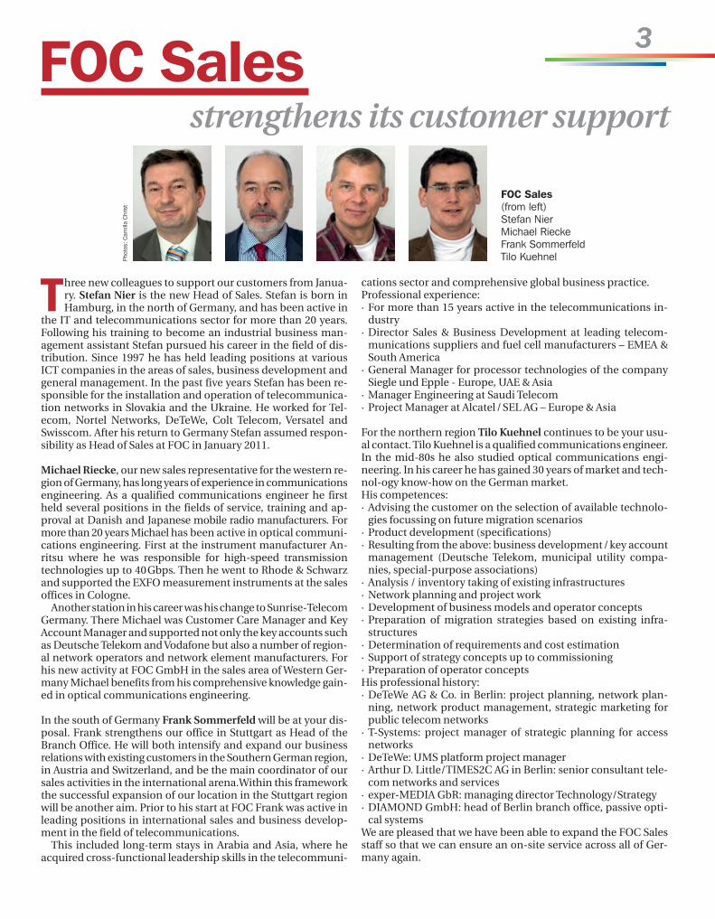
FOC Sales strengthens its customer support
FOC Sales (from left)Stefan NierMichael RieckeFrank SommerfeldTilo KuehnelPh
otos
: Cam
illa
Chr
ist
4
Technologies and infrastructures currently used in Ger-many for supplying industry, commerce and privatehouseholds with broadband connectivity all have one
decisive disadvantage: They are not future-proof.This applies both to the currently most-popular DSL technol-
ogies and to all known wireless technologies such as WIMAX,UMTS and, in the future, LTE (Long Term Evolution).
That’s why it is indispensable to establish an access net-work infrastructure which can easily fulfil all future require-ments (time window of three years or later). This new accessnetwork which has to be installed up to the end customer, i. e.into the homes, is based on optical fibres. An optical fibre isfully future-proof since it can transmit an unlimited amountof bandwidth. For this reason the investments, which cur-rently have to be made to cover the “white spots” on thebroadband map and which are subsidized by public funds,should actually be exclusively spent on the fibre-optical in-frastructure.
With this aim the German Federal Ministry of Economicsand Technology has initiated an innovation competitionwhere the winners shall establish a future-proof innovativebroadband infrastructure for cities and communities.
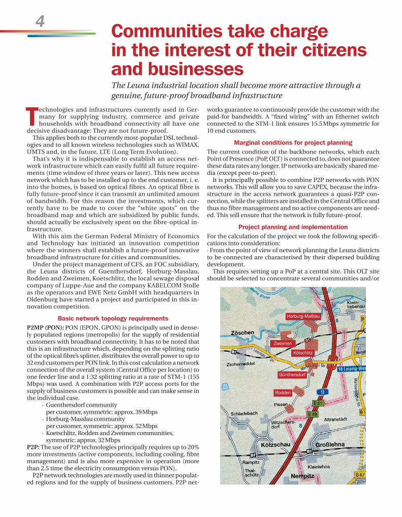
Under the project management of CFS, an FOC subsidiary,the Leuna districts of Guenthersdorf, Horburg-Masslau,Rodden and Zweimen, Koetschlitz, the local sewage disposalcompany of Luppe-Aue and the company KABELCOM Stolleas the operators and EWE Netz GmbH with headquarters inOldenburg have started a project and participated in this in-novation competition.
Basic network topology requirements P2MP (PON): PON (EPON, GPON) is principally used in dense-ly populated regions (metropolis) for the supply of residentialcustomers with broadband connectivity. It has to be noted thatthis is an infrastructure which, depending on the splitting ratioof the optical fibre’s splitter, distributes the overall power to up to32 end customers per PON link. In this cost calculation a networkconnection of the overall system (Central Office per location) toone feeder line and a 1:32 splitting ratio at a rate of STM-1 (155Mbps) was used. A combination with P2P access ports for thesupply of business customers is possible and can make sense inthe individual case.
· Guenthersdorf community per customer, symmetric: approx. 39Mbps
· Horburg-Masslau community per customer, symmetric: approx. 52Mbps
· Koetschlitz, Rodden and Zweimen communities, symmetric: approx. 32Mbps
P2P: The use of P2P technologies principally requires up to 20%more investments (active components, including cooling, fibremanagement) and is also more expensive in operation (morethan 2.5 time the electricity consumption versus PON).
P2P network technologies are mostly used in thinner populat -ed regions and for the supply of business customers. P2P net-
works guarantee to continuously provide the customer with thepaid-for bandwidth. A “fixed wiring” with an Ethernet switchconnected to the STM-1 link ensures 15.5Mbps symmetric for10 end customers.
Marginal conditions for project planningThe current condition of the backbone networks, which eachPoint of Presence (PoP, OLT) is connected to, does not guaranteethese data rates any longer. IP networks are basically shared me-dia (except peer-to-peer).
It is principally possible to combine P2P networks with PONnetworks. This will allow you to save CAPEX, because the infra-structure in the access network guarantees a quasi-P2P con-nection, while the splitters are installed in the Central Office andthus no fibre management and no active components are need -ed. This will ensure that the network is fully future-proof.
Project planning and implementationFor the calculation of the project we took the following specifi-cations into consideration:· From the point of view of network planning the Leuna districtsto be connected are characterised by their dispersed buildingdevelopment.
This requires setting up a PoP at a central site. This OLT siteshould be selected to concentrate several communities and/or
Communities take charge in the interest of their citizensand businesses The Leuna industrial location shall become more attractive through a genuine, future-proof broadband infrastructure
Horburg-Maßlau
Zweimen
Kötschlitz
Günthersdorf
Rodden

5
districts. The OLT site can be implemented at the site of the pre-vious cable distributor/transfer cabinet. A precondition is thatthe OLT/PoP site can be set up on premises owned by the com-munity. As a preparation for the supply of optical fibres to eachhome we recommend setting up a prefabricated container build-ing (see illustration). Furthermore it is assumed that the later
coverage of all communities in the planning area shall be achiev-ed. That is why we recommend setting up a sufficiently sized con-tainer building at the PoP site. With a maximum of 1,200 fibresthis site should offer enough capacity up to final completion ofthe network. A second POP site may be taken into consideration.This second site would not require any additional active or pas-sive components in the actual network to the end customer.
The prefabricated container building is delivered pre-assem-bled on a low-bed trailer and simply placed on the ready-castfoundation trough, where the fibre-optic cables are already in-stalled (see illustration). From here the optical fibres are routedto the households which conclude a contract with the futureoperator. This type of development is based on the actual needs.After setting up the prefabricated container the active compo-nents are installed, the fibres terminated and the customers putinto service. However, prior to installing the optical fibres com-prehensive civil engineering work cannot be avoided. But thiswork was not part of the project calculation. However, the opti-cal fibre has to be routed to each home just once. According totoday’s state of technology we expect that the optical fibre pro-vides unlimited bandwidth and will not be replaced by a com-parable or better technology for at least the next 70 years tocome.
In order to reduce the planning time and effort in the currentphase we assumed hypothetically that all communities in a 20 kmradius (to the last customer) can be reached from this OLT site.
The network has been configured in such a way that all po-tential end customers (all homes along the connected streets,also passed homes) can be connected without any problem. Todo so a house junction box specially developed by EWE Netz
GmbH is used, if needed, from where one optical fibre from themain cable (cut) leads to the respective home. This connectingmethod is cost-saving and requires e. g. an interruption of pe-destrian traffic for a short time only in the form of a one-daybuilding site.
Additionally it may be possible to employ a new house con-
nection method using existing gas service connections. Thismethod has been patented by EWE Netz GmbH.
Furthermore the calculation takes into consideration that thenetwork construction can be performed in the two describedways (PON, PTP).
Both network topologies can be used to implement the well-known triple-play services (phone, Internet, TV). Also the sup-ply of business customers (e. g. w/o TV and/or telephony) in aPON is easily possible (Fig. 3).
Operation of the networkA central network management system for constructing andcommissioning the network and for later monitoring and custo-mer management is included in the project.
First the fibre-optical ring infrastructure for connecting thehouseholds and companies in the respective communitiesneeds to be established. Apart from the tenants of the localshopping centre, several tradesmen, tourism facilities, in parti-cular the Holiday Inn in Guenthersdorf with planned interactiveconnectivity of the hotel rooms, the local medical practice, theinhabitants of the new housing development in Guenthersdorf,which has considerably grown after the fall of the wall in 1989,are particularly interested. So far their connections offered datarates of under 1 Mbps only. Since recently more and more homeworkers, who vitally depend on a good data connection, havebeen moving into the area, there is at least a strong need for ac-tion on the side of the local politicians.
Moreover the improved Internet connectivity shall also im-prove medical care in the area and help meeting the require-ments of a modified primary care in the suburban region.
Fig. 1: Marginal conditions of the project
District Coverage Area Inhabi-tants
Housing units,approx.
Postalcode
Günthersdorf In the old village max. DSL-Light, new hou-sing development not connected 3,26 km2 1.245 500 06237
Horburg-Maßlau Wireless solutions, partly DSL-Light 3,97 km2 543 190 06237
Kötschlitz (including Möritzsch, Zschöchergen) Via CATV, no DSL, 25% not connected 5,40 km2 927 370 06237
Rodden (including Pissen) Wireless solutions with partly just under2Mbps, no DSL 3,61 km2 248 150 06237
Zweimen (including Göhren, Dökau) Relatively well covered, Telekom up to3Mbps 7,31 km2 305 145 06237
FTTH distributor stationUp to 3,000 optical fibres (customers)/siteStation size: 3200 x 6200mmTurnkey delivery (ventilation, guidancesystem, system cabinets, etc.)Station for up to about 3,000 customers
Fig. 2: PoP site
FTTH street cabinetUp to 600 optical fibres(customers)/siteSize: 2200 x 600mmStreet cabinet for about500 customers

6
Fig. 3: Network topology (source: PBN)
Fig. 4: Central network management system (source: PBN)
Highly consistent networks.

7This is particularly meant to counteract the loss of doctors in thearea. The online care of several long-term patients (= chronical-ly ill and old people) living at remote places but also the expan-sion of the diagnostic tools via a data connection to individualinstitutes of the Leipzig university clinic and to other institutionsare the next aims.
Assumption/initial conditionsThe new fibre-optical network is a fail-proof network similar tothe copper-based telephone network. Its yearly availability isabout 99.89 per cent, i. e. statistically about 0.4 days of failure peryear.
Each end customer can decide which TV and radio stationshe/she wants to book and use from a total of 150 available sta -tions. Each service provider, who wants to feed a service into thenetwork, may do so based on its own investment at the PoP.
Through the use of an innovative network monitoring systemon the physical layer each end customer link can be permanent -ly monitored from the central office. This system is provided byFOC GmbH and by Lancier Monitoring GmbH in Muen ster, Ger-many.
The local network remains in the ownership of the communitywhich makes it available to the network operator in the form ofan operating company or an association.
Technical parametersAll installed fibre-optical house connections can use, dependingon the data rates ordered, up to 40 Mbps in the downstream andupstream (symmetric bandwidth distribution). Since each wave-length range transmits just one service, the full bandwidth canbe made available for each service (Fig. 5).
An increase or upgrade of the bandwidths is possible any time.This can be done by leasing a bigger feeder bandwidth (fromSTM-1 to STM-4 or STM-16) or e. g. by implementing P2P con-
Fig. 5: Technical principle of the overall system
nections for business customers.Contrary to the transmission method of TV cable networks,
where Internet and telephony and TV share the same band-width, so that less bandwidth is available for each service, withthe optical transmission method the full bandwidth can be usedby each service.
The customer terminal is directly connected to the optical fibreinstalled in the home. On the other side the device providesports for all three services, such as TV, Internet and telephony.The existing customer devices such as phone, TV-set and PCscan be directly connected to the terminal (Fig. 6).
Tilo Kuehnel, FOC
Fig. 6: Customer terminal for the provision of TV, Internet and te-lephony services

8
The long term experience made by the network operatorshas shown: Contrary to initial expectations fibre-optic ca-bles need to be monitored, too. Environmental influences,
such as water penetrating the cable, have an impact on trans-mission quality. Ruptures due to land slides, construction workor even theft may result in total loss.
In addition to these problems, sufficiently known from the fibre-optic backbone and from long-haul links, technical risks asso-ciated with the residential customer’s premises have to be con-sidered for FTTx. Frequently the network operator does not havethe direct and required access to the line termination, but has torely on the help provided by the end customer for measure-ments and checks. Here you will see, that the vast majority of re-ported failures does not occur in the network area but in custo-mer’s configuration or in the customer’s ONT (Optical NetworkTermination). If the customer reports a problem, the networkoperator is obliged first to check the proper functioning of thenetwork, before demanding from the customer to check/havechecked his/her own configuration. This will frequently causeconsiderable delays and additional cost for the restoration of theconnection.
Moreover, the mere number of connections to the end customeralone renders a periodic manual measurement—as often doneon the backbone today—impossible in the FTTx network.
All these reasons almost inevitably result in the implementationof an automatic monitoring system of the physical PON networkin order to permanently and cost-efficiently maintain the relia-bility of the network. Such an automatic monitoring may be per-formed in an optimum way by a fixed optical backscatter in-strument (OTDR, Optical Time Domain Reflectometer) in com-bination with special reflectors. Figure 1 shows the measure-ment principle: Each customer termination is fitted with a spe-cial reflector reflecting the portions of light used for monitoringpurposes while not influencing the light needed for data trans-mission. For this task special reserved wavelength channels at1625nm or 1650nm are available.
In the backscatter trace each reflector provides a characteristicsignal peak, whose position is determined by the length of thelink between reflector and OTDR. In PON structures the overlayof the individual reflections produces a characteristic overallpicture, similar to a fingerprint, which is recorded at the initial
New methods for monitoring FTTxnetworks
Fig. 1: Measurement principle used for monitoring
CustomerOptical lineCentral Office
Reflector

9
commissioning of the network and later used as a reference (seeFigure 2). Now the monitoring essentially consists in perma-nently performing backscatter measurements and in drawingthe right conclusions from possible deviations, if any.
A fibre break between OLT and splitter, for instance, can quick-ly be identified in the backscatter trace and easily be localised. Afibre break between splitter and customer interface (ONT) is so-
mewhat more complex. First, it can easi ly be identified due tothe missing end reflection in the affected PON branch. In manycases it will be possible to see the new reflection produced by thebreak so that the fault can be localised, as well. However, the re-flection of the fibre break may happen to coincide with the endreflection of another PON branch. In this case the position of thefibre break may sometimes only be localised by another measu-rement performed at one of the signal wavelengths, becausethen the reflection of the break can be distinguished in the back-
scatter trace from the reflectors’ reflections. Such and similaranalyses helping to save much time during troubleshooting aretriggered and controlled by the Remote Testing Unit (RTU).
The RTU is installed in the Central Office (CO). The related high-quality OTDR offers three measurement wavelengths (1310nm,
1550nm and 1625 or 1650nm) and uses the currently smallestpossible dead zones which are necessary to allow a correct mo-nitoring in the PON to be made in the first place. The fibre linksto be monitored are sequentially connected to the OTDR usingan optical switch. Additionally wavelength division multiplexers(WDM) are required to inject the monitoring signal into the mo-nitored links. Then the OTDR performs the measurementthrough the passive splitter into to the customer’s ONT. It asses-
ses the end reflection in order to determine whether the link bet-ween splitter and ONT is functioning properly. In order to obtainperfect measurement results a wavelength-selective reflectorwith a high reflectivity should be used at the ONT. The lilix FTTxreflectors made by FOC, which offer a reflectivity of more than90% in the monitoring channel with less than 0,5dB of additio-nal insertion loss for the traffic wavelengths, have proved to behighly effective here. Figure 3 shows an example of the filter cha-racteristics of these reflectors.
The special PON-optimized OTDR will exactly measure the re-flections, and the RTU then performs the required assessment.If one of the reflections is weaker than expected or even has dis-appeared due to a cable rupture, the RTU will send the corres-ponding message to the central server, which will then inform
In future the customer will attach more attention to service.
Fig. 2: “Fingerprint” of a PON with 1x32 splitter and 5 customer interfaces (ONT)
OLT Splitter ONT

10
the relevant engineers by SMS or e-mail. All available measure-ment data are saved in a central data base and will be availablefor later analyses, e. g. for statistical purposes.Of course, the integration with other systems, frequently exis-ting at the network operator, such as cable management sys-tems or geographic information systems (GIS, mapping) is pos-sible.
The parameterization of the system as well the visualization ofthe measurement data (see Figure 4) can be conveniently per-formed from any client computer in the network via an Internetbrowser. No special software is required.
The company Lancier Monitoring GmbH from Muenster, Ger-many, has been developing and distributing monitoring systemsfor cable networks for more than 40 years. Since the mid-90s thefocus is on fibre-optic cables. Their systems are used by national
and international cable network operators, electric utility com-panies and the large-scale industry.
Torsten Angerhausen, Lancier MonitoringDr. Martina Vitt, FOC
Fig. 3: Filter characteristics of a lilix FTTx reflector
Fig. 4: PON monitoring system from Lancier Monitoring
Transmission
Reflexion
[dB]
Wavelength [nm]
ONT
ONT
ONT
ONT
ONTONT
ONTSplitterSplitter
Splitter
WDM WDM WDM WDM
Splitter

11
This article shows that it is well possible to achieve andguarantee a compatibility within the range of “0.1dB” in-dependent of the connector’s ferrule technology and
thus of the connector set manufacturer.
1. Introduction: connectors and standardisation
Both the geometry of optical connectors and their optical para-meters are standardized. This standardization ensures the qua-lity of the connectors on the one hand and the compatibility bet-ween connectors from different manufacturers and assemblerson the other hand.
The geometry of different connector types, such as E-2000®,
SC or LC, is guaranteed through the standardization of their so-called connecting interfaces (IEC61754 series).
This ensures that e. g. an LC connector from manufacturer “A”can be connected via an adaptor from manufacturer “B” with anLC connector from manufacturer “C”.
However, the standardization of the connecting interfacesalone is not sufficient to predict, assess or guarantee the qualityof a mated connection.
In order to offer the customers an easier comparison of the qua-lity of the optical parameters, classes have been introduced forthe key optical parameters of return loss and insertion loss (seeTable 1).
Compatibility of E-2000® connectors accordingto IEC 61755-1 (Grade A)
Table 1: Singlemode fibre loss classes at 1310nm and 1550nm (source: EN 61755-1)
Loss class Attenuation (>=97%) Average CommentA reservedB <= 0.25 dB <= 0.12 dB
C <= 0.50 dB <= 0.25 dB
D <= 1.00 dB <= 0.50 dB
Fig 1: E-2000® connector system

12
Here we should note that, on the one hand, these classes app-ly to mated connections between connectors of identical fibretypes (e. g. G.652.D or G.657.A) and that, on the other hand, the(loss) limit values for the measurement apply to reference con-nectors only.
While the return loss classes essentially depend on the type ofpolishing (PC or APC), the insertion loss classes have a morecomplex background.
The loss classes are primarily based on the parameters of theoptical interface, or more simply, on the junction between themating connectors. Here the decisive parameters are apex off-set, polishing radius, fibre protrusion, fibre undercut, and tilt
angle. However, these shall not be discussed in this article.Table 1 shows that (although competitors make different sug-
gestions) neither in this table nor in any other standard a “0.1dBclass” (“Grade A”) is defined.
The reason for the absence of such a “Grade A”, which actuallyshould be defined analogue to Table 1, is the fact, that the repre-sentatives of the different connector ferrule technologies (mul-ti-component ferrules and full-ceramic ferrules) have not yetmanaged to agree on a uniform approach, uniform parametersand limits for defining a “Grade A”.
Eventually the definition of a “0.1dB class” or “premium class”,to mention just two examples of possible descriptions, always isvendor-specific for the time being. However, a statement on theattenuation of the mated connectors based on different con-nector ferrule technologies is in the interest of the customer. Ifthe customer wants to decide or already has decided in favour of0.1dB connectors, he does not want to depend on just one con-nector set manufacturer, on the one hand, and on the otherhand he wants that his decision is future-proof.
2. Basics: Connector technologies and
marginal conditionsThe basic differences between connector technologies aremostly known.
When using the multi-component ferrules with core align -ment from the company Diamond the fibre core is exactly posi-tioned in the centre of the ferrule. Thus a residual eccentricity ofthe fibre core of less than 0.125µm can be achieved.
Of course, with full-ceramic ferrules no core alignment is pos-sible. Here an optimum position of the fibre core can be achievedeither by carefully selecting the ferrules (and fibres) or by system-atically placing the residual eccentricity into a standardizedsector.
But also for multi-component ferrules loss values in the rangeof 0.1dB cannot be achieved by core alignment, residual eccen-
tricity values of less than 0.125µm and by complying with thegeometry parameters of the connector surface, alone. The assem-bly process of the multi-component ferrule also has some im-pact on the quality:
I Tight tolerances for tilt angles (<0.4°)
II Strain-free glue curing process for avoiding (wavelength-de-pendent) attenuation caused by microbendings in the fibre
III Optimized polishing processes for avoiding the generationof polymorphic intermediate layers on the connector sur -face
Additionally a 100% final visual inspection of the connector sur-face is required, in order to deliver only those connectors whosesurface does not show any scratches, measurement impressionsor pollutions.
Fig 2: Insertion loss distribution of LC-APC connectors
0.1dB—Future-proof optical connections from FOC.
Dis
trib
utio
n[%]
IL [dB]

133. Challenge: 0.1dB for random mated connectors
independent of ferrule technologyAlready in 2007, when FOC was expanding its connector port fo-lio to include LC-PC and LC-APC connectors, we gained com-prehensive experience as to how connectors with loss values inthe range of 0.1dB can be manufactured using full-ceramic fer-rules.
At that time it proved decisive to combine the qualification ofthe connector set supplier with high-quality and tight-toleranceferrules, and to transfer the above mentioned technological ex-perience gained from the assembly of E-2000® connectors bas edon multi-component ferrules with nickel silver to the full-cera-mic ferrules.
Apart from this experience, in mid-2010 we set ourselves thetask of being able to assemble E-2000® connectors also on thebasis of full-ceramic ferrules, for which we can guarantee lossvalues in the range of 0.1dB.
However, this time the additional challenges were to ensure0.1dB on the one hand without selection and on the other handnot only against reference connectors but against any E-2000®
connector assembled at FOC. To be more specific, the aim wasto manufacture E-2000® connectors based on full-ceramic fer-rules which are fully compatible to E-2000® connectors basedon multi-component ferrules, as FOC has delivered them willcontinue to deliver.
Of course, apart from the decision for one supplier of the con-nector sets in the required quality and from our experience gai-ned in the many years of assembly of LC connectors, furthermeasures were required. Without going too much into technicaldetail here, I’d like to mention just some of them:
IV Identification of fibre manufacturers with the best fibre geo-metry tolerances for minimizing eccentricity and glue joints.
V Optimized semi-automatic fibre cutting process for repeat -able fibre protrusion as a precondition for homogenous pol-ishing patterns.
VI Development of proprietary polishing processes, in order toachieve the best possible compatibility by optimum pol -ishing radii on the one hand, and to minimize fibre undercutand fibre protrusion on the other hand.
From the beginning all these improvement measures were takenwith the aim of a later series manufacture under normal pro-duction conditions.
4. The results prove us right
The results in Figure 3 support our claim. With an appropriatecombination of material and technology FOC is able to manu-facture E-2000® connectors in series, for which we can guaran-tee measured loss values of 0.1dB and better independent of theunderlying ferrule technology of random mated connectors (ac-cording to IEC 61300-3-34).
Dipl. Ing. Axel ThielHead of Development DepartmentFOC
Fig 3: Insertion loss distribution of E-2000® APC connectors based on 100 connectors with multi-component ferrule and full-ceramicferrule respectively
Dis
trib
utio
n[%]
IL [dB]

14
1.lilix Kit—components for optical reflectors
to permanently monitor passive optical network infrastructures
Today optical networks are and will continue to be the backboneof our economy and of individual communication. For this rea-son these networks must be protected from failures. To do so,faults should be identified as soon as possible.
The FOC monitoring concept using wavelength-selective re-flectors consists in localising the optical reflection generated bythe reflector at the customer-side end “B” by means of unilate-ral backscatter measurements from the central location (end“A”), and in properly assigning this reflection to the correspon-ding end “B”. In this way the individual fingerprint of the net-work is recorded already in the installation phase of the network.During later network operation follow-up measurements of thisfingerprint simplify troubleshooting and allow you to monitorlong-term deviations of critical network parameters.
We will explain the basic idea behind this type of network mo-nitoring and use practical examples to show how to streamlinefault identification and analysis eventually saving OPEX.
2.Compatibility of connectors according
to IEC 61755-1 (Grade A)The currently available components according to IL Class A, beit “0.1dB Class” or “Premium”, just to mention two examples, arebased on manufacturer-specific descriptions.
However the customer is interested in a statement on the at-tenuation of the mated connectors based on an internationalstandard, in particular when mating different connector ferruletechnologies.
Anyone who wants to decide in favour of a 0.1dB connector orhas already done so, must see some sustainability in his deci sionand implement it.
During assembly the challenge is to technically fulfil the re-quirements of IEC 61755-1 in such a way that the optical valuesof “Grade A” can be achieved for the mated connection in thenetwork independent of the technology and the assembler.FOC has met this challenge. We want to present this technology
to you and discuss our initial experience gained in the manu-facture of connectorized patchcords with you.
3. Video-microscopes—what for?
Frequently fibre-optical links are terminated on pigtails and insplice boxes on adapters, without putting them into service. Ifthese links are connected and patched later, baseline measure-ments often show considerable increases in attenuation up tocomplete “malfunction”. Troubleshooting is difficult, because“dirty” connectors cannot be exactly identified.
One possibility to do just this is inspecting the connector end-faces with a video microscope.
As mentioned above in the short introduction this year wewould like to discuss the following topics with you:
1. lilix Kit—components for optical reflectors to permanentlymonitor passive optical network infrastructures
2. IEC 61755-1 in practical test3. Video-microscopes – what for?
We would be pleased to welcome you and/or your colleagues inour house.Please select a date and register via fax (+49 30 565507-19) or e-mail ([email protected]).
The FOC workshop talks will be held from 11 hrs to 15 hrs on:
· Thursday, 24 February, at the Berlin central office · Thursday, 07 April, at the Berlin central office · Thursday, 19 May, at the Stuttgart branch office· Thursday, 26 May, at Park Inn Hotel, Duesseldorf Sued· Thursday, 06 October, at the Stuttgart branch office
We look forward to interesting talks with you.Yours sincerely,
Christian Kutza, Managing Director
FOC workshop talks
2011
Topics and dates

15
In the past we still were quite well off in Germany. But the firstweaknesses appear. I speak of vocational education and qua-lification. For many years vocational training leading to a
skilled worker’s certificate was a usual step in the career of manyof us.
With amazement we have had to note a certain loss of qualityand quantity also in Germany for some years now. This appliesin particular to practical, vocational training. 20 years ago wehad apprenticed trades in the area of communications and tele-communications industries linked with a high portion of op-portunities for theoretical learning and practical, manual train -ing.
During vocational training to become a skilled communica -tions engineer specialised in communications lines the appren-tices in Germany used to learn how to splice copper wires, in-cluding the subsequent restoration of the cable sheath by solde-ring lead sleeves, to mention just one example.
Is this still the case today? Or are we moving more and moretowards a situation—as has been the case in other EU countriesfor long—that the highly qualified technical trades degenerateto “semiskilled” activities. If this is the case, this development isbound to have impacts on quality, in particular of telecommu-nications and data networks. But don’t we risk losing some of thefew competitive advantages which we still enjoy, i. e. to installand operate fail-proof quality networks? Does the cost pressurein all areas inevitably result in a situation where we reach thesame low-quality level as our competitor nations through a lackof qualification among the staff in the future? Should quality notbe a German virtue and thus a competitive advantage, which islinked to the term of “Made in Germany” and which thus shouldbe preserved? There is much room for discussion and philoso-phical talk here.
In fact: The better the qualification of those working on opti-cal networks, the better the quality of their work.
This is the aim the organisers of the joint seminars are com-mitted to. By improving the theoretical and practical compe-tence the quality level of the work done in these operators’ net-works shall be increased.
»An investment in the future« or training does good.
20 years in the service of optical technologies
Fibre-optic joint seminars
When?· 08 June and 09 June 2011Where?· Berlin-Adlershof Science Park, Germany
What? · Broadband in Germany—Interim results
and prospects· Optical networks—Infrastructure of a
new generation· Energy efficiency—Road into the future· Optical fibres—Measuring technology· Wavelength-division multiplex: WDM,
CWDM, DWDM· FTTH: The gigabit society· New dimensions of data centres· Internet—the new (in)security
How?· Exhibition· Plenum· Workshop Who should attend?· Local administrations, city utility com-
panies, data centres, housing societies,network operators and owners
· Manufacturer, planning agencies, instal-lers and technical management
· Universities and colleges
Let’s take a Quantum Leap!
Here Comes the Second Hit
BEL..2.is approaching
Broadband + Energy Efficiency =Fibre Optic Technology
Rework, often caused by ignorance and technical errors, has be-come a daily routine today. Also the reporting of final and ac-ceptance measurements for handing over the network to thecustomer (network operator) frequently is not sufficiently mean-ingful or even wrong.
In order to counteract an expected training emergency in thepractical fields in this industry the organisers of the Joint Semi-nars, where FOC is part of, have prepared and launched a trainingprogramme at the manufacturers of passive and active systemsand components. In this connection FOC and other partner ma-nufacturers have fitted 100 sqm of space with the requiredequipment. (Fotos Technikraum) Thus practical training as wellas later practical use of the newly acquired knowledge is guaran -teed. Qualified specialists who have many years of experiencewill work as instructors.
Together with TÜV Rheinland training and examinations con-cepts have been prepared containing several practical and theo-retical questions, tasks and contents.
As a result, the participants leave the training sessions as spe-cialists, on request, also certified, for fibre installation and as-sembly. They will thus have more chances on the labour marketand a lead over their employers in terms of knowledge andpractice.
Christian Kutza and Fritz Schwarz had the idea for this train -ing and qualification concept 20 years ago. Since then, over 300seminars with more than 4,500 participants have been held. 70top-class lecturers from science and industry have passed ontheir knowledge and skills.
Now there is another branch of qualification available: Practi-cal work and training on different products. The products havebeen made available by many partners. The basic idea is that theseminar and training participants need not go from company tocompany in order to familiarize themselves with the differentproducts in the market.
Of course, FOC GmbH will continue to actively participate inthe qualification seminars and also make an appropriate contri-bution at this year’s BEL 2 fair from 08 to 09 June 2011 in Berlin-Adlershof, Germany.

In the Berlin-Adlershof Technology Park.
BERLIN
Adlergestell
Rudow
er Cha
usse
e
Rudower Chaussee
Ernst-Ruska-Ufer
Albert
-Eins
tein-
Straß
e
Justu
s-von
-
Lieb
ig-St
r.
Am Studio
Wegedornstraße
Dörpfeldstraße
Zentrum
�
Schönefeld
�
96a
96a
�
A113
Adlershof
FOC–fibre optical components GmbH HeadquartersJustus-von-Liebig-Straße 712489 Berlin/Germanyphone: + 49 30 565507- 0fax: + 49 30 565507-19e-mail: [email protected]
Sales region southZettachring 10a70567 Stuttgart/Germanyphone: + 49 711 745191-90fax: + 49 711 745191-91e-mail: [email protected]
Sales region westAnsbacher Straße 1940597 Düsseldorf/Germanyphone: +49 211 695176-09fax: + 49 211 59841871e-mail: [email protected]
Subject to change without notice.
Contacts
fibre optical components GmbH©
WIS
TA-M
G –
ww
w.ad
lers
hof.d
e
www.foc-fo.com
Details on how to contact our staff can be found in the Internetat www.foc-fo.com, Contacts, Direct contacts.