fisherrposi-seal™1035/el-o-matic...
TRANSCRIPT
www.Fisher.com
Fisherr POSI-SEAL™ 1035/El-O-MaticRack-and-Pinion Rotary ActuatorContentsIntroduction 1. . . . . . . . . . . . . . . . . . . . . . . . . . . . . . . . .Scope of Manual 1. . . . . . . . . . . . . . . . . . . . . . . . . . . . .Description 2. . . . . . . . . . . . . . . . . . . . . . . . . . . . . . . . .Specifications 2. . . . . . . . . . . . . . . . . . . . . . . . . . . . . . .Installation 4. . . . . . . . . . . . . . . . . . . . . . . . . . . . . . . . . .Operation 6. . . . . . . . . . . . . . . . . . . . . . . . . . . . . . . . . . .Adjustment 12. . . . . . . . . . . . . . . . . . . . . . . . . . . . . . . .Troubleshooting 12. . . . . . . . . . . . . . . . . . . . . . . . . . . . .Maintenance 13. . . . . . . . . . . . . . . . . . . . . . . . . . . . . . . .Actuator Disassembly 13. . . . . . . . . . . . . . . . . . . . . . .Actuator Assembly 16. . . . . . . . . . . . . . . . . . . . . . . . . .
Changing Rotation Direction 18. . . . . . . . . . . . . .Spring Return E Series Actuators 20. . . . . . . . . . .Spring Return P Series Actuators 20. . . . . . . . . . .Installing the Bypass Valve 20. . . . . . . . . . . . . . . .
Parts Ordering 21. . . . . . . . . . . . . . . . . . . . . . . . . . . . . . .Parts Kits 22. . . . . . . . . . . . . . . . . . . . . . . . . . . . . . . . . . .Parts List 23. . . . . . . . . . . . . . . . . . . . . . . . . . . . . . . . . . .
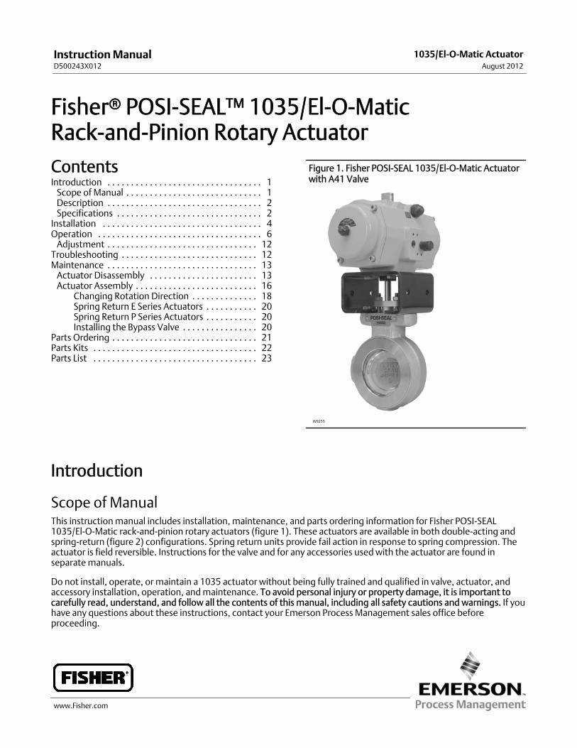
Figure 1. Fisher POSI-SEAL 1035/El-O-Matic Actuatorwith A41 Valve
W9255
Introduction
Scope of ManualThis instructionmanual includes installation, maintenance, and parts ordering information for Fisher POSI-SEAL1035/El-O-Matic rack-and-pinion rotary actuators (figure 1). These actuators are available in both double-acting andspring-return (figure 2) configurations. Spring return units provide fail action in response to spring compression. Theactuator is field reversible. Instructions for the valve and for any accessories used with the actuator are found inseparatemanuals.
Do not install, operate, or maintain a 1035 actuator without being fully trained and qualified in valve, actuator, andaccessory installation, operation, andmaintenance. To avoid personal injury or property damage, it is important tocarefully read, understand, and follow all the contents of this manual, including all safety cautions and warnings. If youhave any questions about these instructions, contact your Emerson Process Management sales office beforeproceeding.
InstructionManualD500243X012
1035/El-O-Matic ActuatorAugust 2012
InstructionManualD500243X012
1035/El-O-Matic ActuatorAugust 2012
2
Table 1. Specifications
1035 Actuator:
Double Acting Spring Return.EDA 25 ESA 25EDA 40 ESA 40EDA 65 ESA 65EDA 100 ESA 100EDA 200 ESA 200EDA 350 ESA 350EDA 600 ESA 600EDA 950 ESA 950EDA 1600 ESA 1600PDA 2500 PSA 2505PDA 4000 PSA 4005
Output Shaft:J Double D insert for A41 valvesJ Optional ISO 5211 square insert,J Recessed ISO5211 square drive for P Series actuators
Dual Stop Adjustment:J E Series actuators arefurnished with dual stop adjustments (DSA) as astandard feature.J P Series actuators provide dualstops with the use of the “Limit Stop Plate” (LSP)option. The LSP is mounted between the actuator andyoke.
Supply Pressure(1) (Operating Pressure)
2.8 to 8.3 bar (40 to 120 psig) for both double actingand spring return actuators
Temperature Range(1)
Standard: -20 to 79_C (-4 to 175_F) with NitrileO-ringsOptional:High Temperature: -20 to 121_C (-4 to 250_F) withfluorocarbon O-rings (a “V” inmodel number), or Low
Temperature: -40 to 79_C (-40 to 175_F) with EPDMand special lubricant (an “LT” inmodel number)
Performance Characteristics
See tables 2 and 3
Rotation for Code A Construction
Rotation is counterclockwise with port “A”pressurized with standard code A construction.Spring return actuators fail clockwise with standardconstruction for standard code A actuators (seefigure 3 for optional constructions)
MaximumOutput Torque
See Catalog 14
Lubrication
Factory lubricated for the normal life of the actuator(see temperature range shown above)
Coating
All units feature a two component polyurethanecoating system as standard
Actuator Tubing Size
3/8 inch O.D. standard for all sizes
Options
J Parts kits: O-ring kits provides O-rings only, andrepair kits provide O-rings, guide bushings and softparts. Kits are available for standard and hightemperature or for low temperature applicationsJ Unit is field reversible
1. The pressure-temperature limits in this manual and any applicable code or standard installation should not be exceeded.2. For more information, contact your Emerson Process Management sales office.
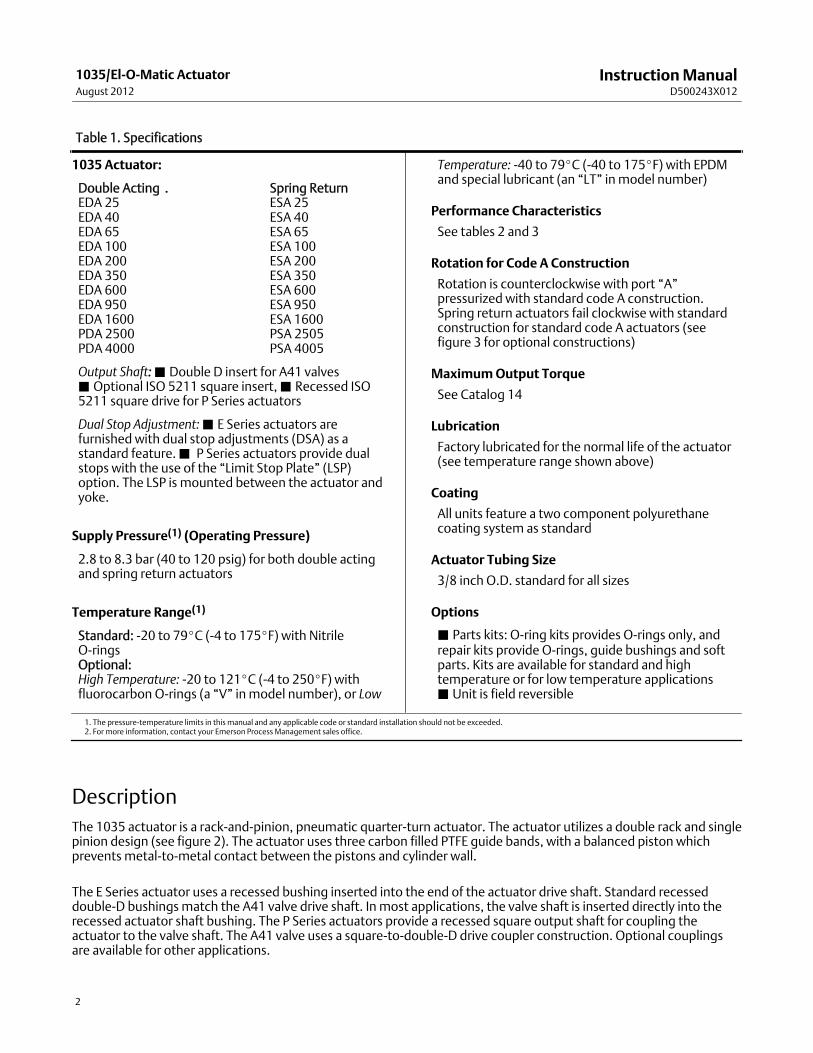
DescriptionThe 1035 actuator is a rack-and-pinion, pneumatic quarter-turn actuator. The actuator utilizes a double rack and singlepinion design (see figure 2). The actuator uses three carbon filled PTFE guide bands, with a balanced piston whichprevents metal-to-metal contact between the pistons and cylinder wall.
The E Series actuator uses a recessed bushing inserted into the end of the actuator drive shaft. Standard recesseddouble-D bushingsmatch the A41 valve drive shaft. In most applications, the valve shaft is inserted directly into therecessed actuator shaft bushing. The P Series actuators provide a recessed square output shaft for coupling theactuator to the valve shaft. The A41 valve uses a square-to-double-D drive coupler construction. Optional couplingsare available for other applications.
InstructionManualD500243X012
1035/El-O-Matic ActuatorAugust 2012
3
Table 2. Performance Characteristics
E SERIESACTUATOR
SIZE
BORE STROKE AVERAGESTROKETIME(SEC)(1)
FREE AIR VOLUME(2) FREE AIRVOLUME(2)
mm Inch mm Inch Port“A”(liter)
Port“A”(in3)
Port“B”(liter)
Port“B”(in3)
E25 56 2.2 15.7 0.62 0.5 0.1 6.1 0.11 6.7
E40 70 2.8 18.8 0.74 0.7 0.16 9.8 0.22 13.4
E85 80 3.1 22.0 0.87 1.1 0.33 20.1 0.36 22.0
E100 91 3.6 25.1 0.99 1.2 0.35 21.4 0.49 29.9
E200 110 4.3 37.7 1.48 2.2 0.8 48.8 1.0 61.0
E350 145 5.7 37.7 1.48 3.7 1.8 110 1.9 116
E600 175 6.9 44.0 1.73 3.3 2.9 177 3.1 189
E950 200 7.9 50.3 1.98 5.4 4.7 287 4.9 299
E1600 230 9.1 62.8 2.47 5.8 7.3 445 8.0 488
P2500/P2505 300 11.8 56.5 2.22 6.7 8.0 488 9.3 567
P4000/P4005 325 12.8 81.7 3.22 12.4 13.5 824 17.5 10681. These times assume smaller solenoids for smaller actuators and larger solenoids for larger actuators with varying Cvs, but a constant air supply pressure of 80 psi (5.51 bar). E25 to E350assume a 0.09 Cv (0.08 Kv); E600 & E9500 a 0.26 Cv (0.22 Kv); E1600, P2505 & P4005 a 0.51 Cv (0.44 Kv).2. To calculate air consumption per strokemultiply free air volume X air supply pressure (absolute).
Figure 2. Typical Actuator Assembly
SPRING
STANDARD SQUARE END
STANDARD SQUAREDOUBLEDCONNECTION
COUPLER
DOUBLE ACTINGACTUATOR
E SERIES INSERTEND CAP SPRING RETURN
W6954
InstructionManualD500243X012
1035/El-O-Matic ActuatorAugust 2012
4
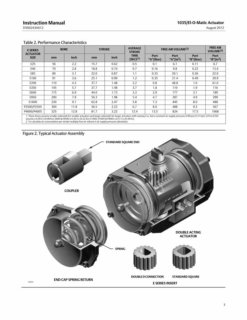
Table 3. ApproximateWeights
ACTUATOR SIZEkg lbs
EDA ESA EDA ESA
E25 1.2 1.7 2.7 3.7
E40 1.8 2.4 4.0 5.3
E65 2.4 3.6 5.3 7.9
E100 2.8 4.6 6.1 10.1
E200 5.8 9.1 12.8 20.1
E350 10.4 16.9 22.9 37.3
E600 19.4 27.6 42.8 60.8
E900 26.4 38.6 58.2 85.0
E1600 42.7 65.8 94.1 145
P2500/P2505 56.7 88.0 125 194
P4000/P4005 86.2 132.0 190 291
Table 4. Bolting Torques between 1035 and YokeACTUATOR SIZE Bolt Diameter, Inches Torque, NSm Torque, lbfSft
E25 1/4 11 8.3
E40E65E100
5/16 22 16.5
E200E350
3/8 39 29
E600 1/2 91 67
E950 5/8 163 120
E1600 3/4 258 190
P2500/P2505P4000/P4005
3/4 203 150
InstallationWhen an actuator and a valve are shipped together, the actuator is normally mounted on the valve. Follow the valvebody instructions when installing the control valve in the pipeline. If the actuator is shipped separately from the valveor if it is necessary tomount the actuator on the valve, perform the procedures in the Actuator Mounting section.
WARNING
Alwayswear protective gloves, clothing, and eyewear when performing any installation operations to avoid personalinjury.
To avoid personal injury or property damage caused by bursting of pressure-retaining parts, be certain the serviceconditions do not exceed the limits given in table 1. Use pressure-limiting devices or pressure-relieving devices to preventthe cylinder pressure from exceeding these limits.
If hoisting the valve and actuator assembly or the actuator by itself, take precautions to prevent people from being injuredin case the hoist or sling slips unexpectedly. Refer to table 3 for actuator weights. Carefully position the sling to preventdamage to tubing or any accessories.
Checkwith your process or safety engineer for any additional measures thatmust be taken to protect against processmedia.
If installing into an existing application, also refer to theWARNING at the beginning of theMaintenance section in thisinstructionmanual.
InstructionManualD500243X012
1035/El-O-Matic ActuatorAugust 2012
5
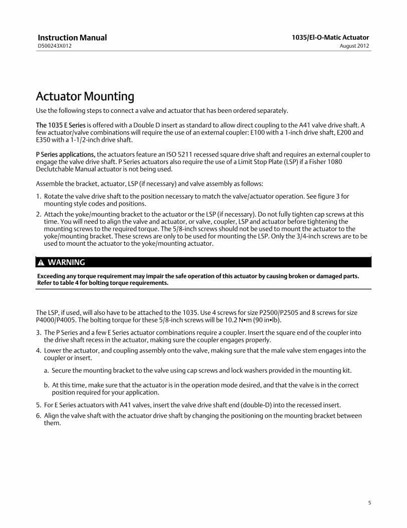
Actuator MountingUse the following steps to connect a valve and actuator that has been ordered separately.
The 1035 E Series is offered with a Double D insert as standard to allow direct coupling to the A41 valve drive shaft. Afew actuator/valve combinations will require the use of an external coupler: E100 with a 1-inch drive shaft, E200 andE350 with a 1-1/2-inch drive shaft.
P Series applications, the actuators feature an ISO 5211 recessed square drive shaft and requires an external coupler toengage the valve drive shaft. P Series actuators also require the use of a Limit Stop Plate (LSP) if a Fisher 1080Declutchable Manual actuator is not being used.
Assemble the bracket, actuator, LSP (if necessary) and valve assembly as follows:
1. Rotate the valve drive shaft to the position necessary tomatch the valve/actuator operation. See figure 3 formounting style codes and positions.
2. Attach the yoke/mounting bracket to the actuator or the LSP (if necessary). Do not fully tighten cap screws at thistime. You will need to align the valve and actuator, or valve, coupler, LSP and actuator before tightening themounting screws to the required torque. The 5/8-inch screws should not be used tomount the actuator to theyoke/mounting bracket. These screws are only to be used for mounting the LSP. Only the 3/4-inch screws are to beused tomount the actuator to the yoke/mounting actuator.
WARNING
Exceeding any torque requirementmay impair the safe operation of this actuator by causing broken or damaged parts.Refer to table 4 for bolting torque requirements.
The LSP, if used, will also have to be attached to the 1035. Use 4 screws for size P2500/P2505 and 8 screws for sizeP4000/P4005. The bolting torque for these 5/8-inch screws will be 10.2 NSm (90 inSlb).
3. The P Series and a few E Series actuator combinations require a coupler. Insert the square end of the coupler intothe drive shaft recess in the actuator, making sure the coupler engages properly.
4. Lower the actuator, and coupling assembly onto the valve, making sure that themale valve stem engages into thecoupler or insert.
a. Secure themounting bracket to the valve using cap screws and lock washers provided in themounting kit.
b. At this time, make sure that the actuator is in the operationmode desired, and that the valve is in the correctposition required for your application.
5. For E Series actuators with A41 valves, insert the valve drive shaft end (double-D) into the recessed insert.
6. Align the valve shaft with the actuator drive shaft by changing the positioning on themounting bracket betweenthem.
InstructionManualD500243X012
1035/El-O-Matic ActuatorAugust 2012
6
OperationUnits supplied from the factory as an assembly are adjusted per specifications supplied to the factory on the originalorder.
Unless the valve/actuator assembly has been damaged during shipment, or the actuator removed formaintenance,the assembly should be factory adjusted and ready for service.
Actuator Orientation: The 1035 actuator is normally installed with its major axis parallel to the pipeline (see code A,figure 3). However, the actuator can also be oriented 90 degrees to the pipeline. See figure 3 for standard and optionalorientations. (Note: Code B is not available in the E Series.)
The P or E Series actuator drive shaft turns a full 90 degrees and the stroke is adjustable for the valve closed position.When necessary, refer to the actuator adjustment steps in this manual.
Note
The A41 High Performance Butterfly valve should not be turned by the power actuator more than 90 degrees of rotation.Pre-adjust actuator stops to limit travel to 90 degrees or less until adjustment steps are completed.
A double acting actuator can be changed in the field to a spring return unit, or vice-versa (requires different end caps).Code A actuators can be converted to a code D unit by turning the pistons 180 degrees from the position shown forcode A (See figure 3 for piston and shaft orientation).
AdjustmentsE Series actuators provide end cap adjustment screws to limit outward travel of the piston. The inwardmovement ofthe piston is limited by the housing stop (see figure 4).
P Series actuators have a Limit Stop Plate option (LSP) which is used with standard actuator constructions. The LSP isnot used when a Fisher 1080 is used. The LSP, or the 1080, limits travel in either direction for any construction. Refer tofigure 4.
To adjust the travel stops, refer to the valve instructionmanual for open and closed positions of the valve. Uponassembly, ensure that the power actuator does not drive the valve past 90 degrees of rotation. Valve component partscan be damaged if high actuator air pressure is applied past 90 degrees. Travel limits must be set in the actuator, not inthe valve. It is recommended that the valve be out of the pipeline when adjusting travel limits.
InstructionManualD500243X012
1035/El-O-Matic ActuatorAugust 2012
7
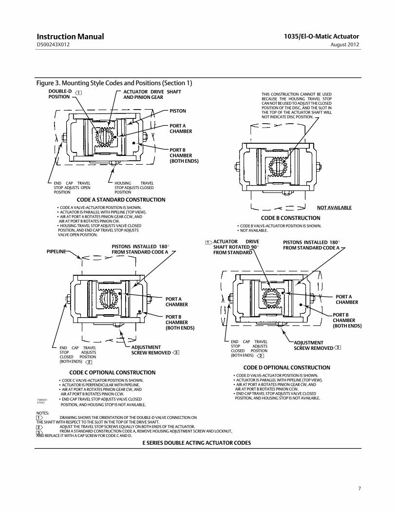
Figure 3. Mounting Style Codes and Positions (Section 1)1
E SERIES DOUBLE ACTING ACTUATOR CODES
CODE A STANDARD CONSTRUCTION• CODE A VALVE-ACTUATOR POSITION IS SHOWN.• ACTUATOR IS PARALLELWITH PIPELINE (TOP VIEW).• AIR AT PORT A ROTATES PINION GEAR CCW, ANDAIR AT PORT B ROTATES PINION CW.• HOUSING TRAVEL STOP ADJUSTS VALVE CLOSEDPOSITION, AND ENDCAP TRAVEL STOP ADJUSTSVALVE OPEN POSITION.
CODE DOPTIONAL CONSTRUCTION•CODE D VALVE-ACTUATOR POSITION IS SHOWN.• ACTUATOR IS PARALLELWITH PIPELINE (TOP VIEW).• AIR AT PORT A ROTATES PINION GEAR CW, ANDAIR AT PORT B ROTATES PINION CCW.• END CAP TRAVEL STOP ADJUSTS VALVE CLOSEDPOSITION, ANDHOUSING STOP IS NOT AVAILABLE.
CODE C OPTIONAL CONSTRUCTION• CODE C VALVE-ACTUATOR POSITION IS SHOWN.• ACTUATOR IS PERPENDICULARWITH PIPELINE.• AIR AT PORT A ROTATES PINION GEAR CW, ANDAIR AT PORT B ROTATES PINION CCW.• END CAP TRAVEL STOP ADJUSTS VALVE CLOSEDPOSITION, ANDHOUSING STOP IS NOT AVAILABLE.
CODE B CONSTRUCTION• CODE B VALVE-ACTUATOR POSITION IS SHOWN.• NOT AVAILABLE.
THIS CONSTRUCTION CANNOT BE USEDBECAUSE THE HOUSING TRAVEL STOPCANNOTBEUSEDTOADJUSTTHECLOSEDPOSITION OF THE DISC, AND THE SLOT INTHE TOP OF THE ACTUATOR SHAFT WILLNOT INDICATE DISC POSITION.
PORT ACHAMBER
PORT BCHAMBER(BOTH ENDS)
DOUBLE-DPOSITION
PORT BCHAMBER(BOTH ENDS)
PORT BCHAMBER(BOTH ENDS)
PORT ACHAMBER
HOUSING TRAVELSTOP ADJUSTS CLOSEDPOSITION
END CAP TRAVELSTOP ADJUSTS OPENPOSITION
END CAP TRAVELSTOP ADJUSTSCLOSED POSITION(BOTH ENDS)
END CAP TRAVELSTOP ADJUSTSCLOSED POSITION(BOTH ENDS)
ACTUATOR DRIVE SHAFTAND PINIONGEAR
PISTON
PISTONS INSTALLED 180_FROM STANDARD CODE A
ADJUSTMENTSCREWREMOVED
PORT ACHAMBER
PISTONS INSTALLED 180_FROM STANDARD CODE A
ADJUSTMENTSCREWREMOVED
ACTUATOR DRIVESHAFT ROTATED 90_FROM STANDARD
NOTAVAILABLE
PIPELINE
NOTES:DRAWING SHOWS THE ORIENTATION OF THE DOUBLE-D VALVE CONNECTION ON
THE SHAFTWITH RESPECT TO THE SLOT IN THE TOP OF THE DRIVE SHAFT.ADJUST THE TRAVEL STOP SCREWS EQUALLY ON BOTH ENDS OF THE ACTUATOR.FROMA STANDARD CONSTRUCTION CODE A, REMOVE HOUSING ADJUSTMENT SCREW AND LOCKNUT,
AND REPLACE ITWITH A CAP SCREW FOR CODE C ANDD.
1
2
33
2
32
75B0451A7043
1
InstructionManualD500243X012
1035/El-O-Matic ActuatorAugust 2012
8
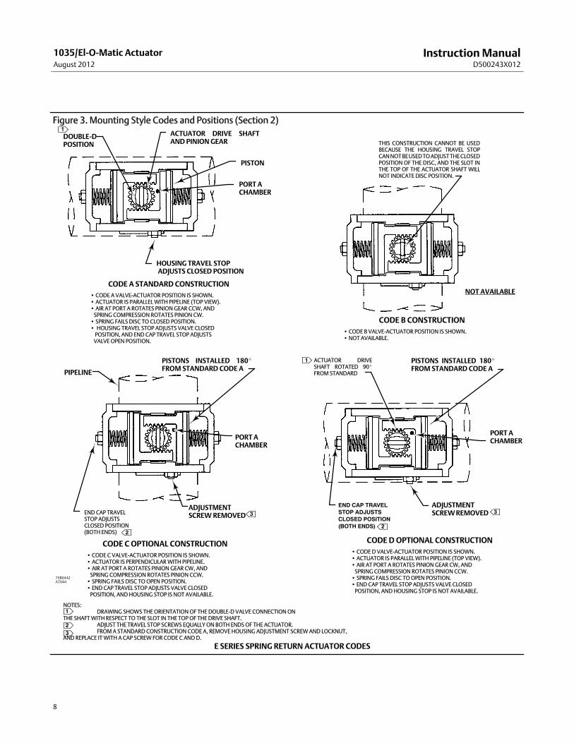
Figure 3. Mounting Style Codes and Positions (Section 2)
E SERIES SPRING RETURN ACTUATOR CODES
CODE A STANDARD CONSTRUCTION• CODE A VALVE-ACTUATOR POSITION IS SHOWN.• ACTUATOR IS PARALLELWITH PIPELINE (TOP VIEW).• AIR AT PORT A ROTATES PINION GEAR CCW, ANDSPRING COMPRESSION ROTATES PINION CW.• SPRING FAILS DISC TO CLOSED POSITION.• HOUSING TRAVEL STOP ADJUSTS VALVE CLOSEDPOSITION, AND ENDCAP TRAVEL STOP ADJUSTSVALVE OPEN POSITION.
CODE DOPTIONAL CONSTRUCTION• CODE D VALVE-ACTUATOR POSITION IS SHOWN.• ACTUATOR IS PARALLELWITH PIPELINE (TOP VIEW).• AIR AT PORT A ROTATES PINION GEAR CW, ANDSPRING COMPRESSION ROTATES PINION CCW.• SPRING FAILS DISC TOOPEN POSITION.• END CAP TRAVEL STOP ADJUSTS VALVE CLOSEDPOSITION, ANDHOUSING STOP IS NOT AVAILABLE.
CODE COPTIONAL CONSTRUCTION• CODE C VALVE-ACTUATOR POSITION IS SHOWN.• ACTUATOR IS PERPENDICULARWITH PIPELINE.• AIR AT PORT A ROTATES PINION GEAR CW, ANDSPRING COMPRESSION ROTATES PINION CCW.• SPRING FAILS DISC TOOPEN POSITION.• END CAP TRAVEL STOP ADJUSTS VALVE CLOSEDPOSITION, ANDHOUSING STOP IS NOT AVAILABLE.
CODE B CONSTRUCTION• CODE B VALVE-ACTUATOR POSITION IS SHOWN.• NOT AVAILABLE.
THIS CONSTRUCTION CANNOT BE USEDBECAUSE THE HOUSING TRAVEL STOPCANNOTBEUSEDTOADJUSTTHECLOSEDPOSITION OF THE DISC, AND THE SLOT INTHE TOP OF THE ACTUATOR SHAFT WILLNOT INDICATE DISC POSITION.
PORT ACHAMBER
DOUBLE-DPOSITION
PORT ACHAMBER
HOUSING TRAVEL STOPADJUSTS CLOSED POSITION
END CAP TRAVELSTOP ADJUSTSCLOSED POSITION(BOTH ENDS)
END CAP TRAVELSTOP ADJUSTSCLOSED POSITION(BOTH ENDS)
ACTUATOR DRIVE SHAFTAND PINIONGEAR
PISTON
PISTONS INSTALLED 180_FROM STANDARD CODE A
ADJUSTMENTSCREWREMOVED
PORT ACHAMBER
PISTONS INSTALLED 180_FROM STANDARD CODE A
ADJUSTMENTSCREWREMOVED
ACTUATOR DRIVESHAFT ROTATED 90_FROM STANDARD
NOT AVAILABLE
PIPELINE
1
2
3 3
2
1
NOTES:DRAWING SHOWS THEORIENTATION OF THE DOUBLE-D VALVE CONNECTIONON
THE SHAFTWITH RESPECT TO THE SLOT IN THE TOP OF THE DRIVE SHAFT.ADJUST THE TRAVEL STOP SCREWS EQUALLY ON BOTH ENDS OF THE ACTUATOR.FROMA STANDARD CONSTRUCTION CODE A, REMOVE HOUSING ADJUSTMENT SCREWAND LOCKNUT,
AND REPLACE ITWITH A CAP SCREW FOR CODE C ANDD.
1
32
75B0442A7044
InstructionManualD500243X012
1035/El-O-Matic ActuatorAugust 2012
9
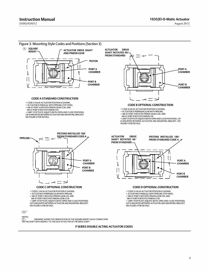
Figure 3. Mounting Style Codes and Positions (Section 3)
P SERIES DOUBLE ACTING ACTUATOR CODES
CODE A STANDARD CONSTRUCTION• CODE A VALVE-ACTUATOR POSITION IS SHOWN.• ACTUATOR IS PARALLELWITH PIPELINE (TOP VIEW).• AIR AT PORT A ROTATES PINION GEAR CCW, ANDAIR AT PORT B ROTATES PINION CW.• LIMIT STOP PLATE ADJUSTS BOTH OPEN AND CLOSE POSITIONS.LSP ISMOUNTED BETWEEN ACTUATOR ANDMOUNTING BRACKET.SEE FIGURE 4 FOR DETAILS.
CODE DOPTIONAL CONSTRUCTION•CODE D VALVE-ACTUATOR POSITION IS SHOWN.• ACTUATOR IS PARALLELWITH PIPELINE (TOP VIEW).• AIR AT PORT A ROTATES PINION GEAR CW, ANDAIR AT PORT B ROTATES PINION CCW.• LIMIT STOP PLATE ADJUSTS BOTH OPEN AND CLOSE POSITIONS.LSP IS MOUNTED BETWEEN ACTUATOR AND MOUNTING BRACKET.SEE FIGURE 4 FOR DETAILS.
CODE COPTIONAL CONSTRUCTION• CODE C VALVE-ACTUATOR POSITION IS SHOWN.• ACTUATOR IS PERPENDICULARWITH PIPELINE.• AIR AT PORT A ROTATES PINION GEAR CW, ANDAIR AT PORT B ROTATES PINION GEAR CCW.• LIMIT STOP PLATE ADJUSTS BOTH OPEN AND CLOSE POSITIONS.LSP ISMOUNTED BETWEEN ACTUATORANDMOUNTING BRACKET.SEE FIGURE 4 FOR DETAILS.
CODE B OPTIONAL CONSTRUCTION•CODE B VALVE-ACTUATOR POSITION IS SHOWN.• ACTUATOR IS PERPENDICULARWITH PIPELINE.• AIR AT PORT A ROTATES PINION GEAR CCW, ANDAIR AT PORT B ROTATES PINION CW.•LIMITSTOPPLATEADJUSTSBOTHOPENANDCLOSEPOSITIONS. LSPIS MOUNTED BETWEEN ACTUATOR AND MOUNTING BRACKET. SEEFIGURE 4 FOR DETAILS.
PORT ACHAMBER
PORT ACHAMBER
ACTUATOR DRIVE SHAFTAND PINION GEAR
PISTON
PISTONS INSTALLED 180_FROMSTANDARDCODEA
PORT ACHAMBER
PISTONS INSTALLED 180_FROM STANDARD CODE A
ACTUATOR DRIVESHAFT ROTATED 90_FROM STANDARD
PIPELINE
PORT BCHAMBER
PORT BCHAMBER
ACTUATOR DRIVESHAFT ROTATED 90_FROM STANDARD
PORT BCHAMBER
PORT ACHAMBER
PORT BCHAMBER
SQUAREINSERT
NOTES:DRAWING SHOWS THE ORIENTATION OF THE SQUARE INSERT VALVE CONNECTION
ON THE SHAFTWITH RESPECT TO THE SLOT IN THE TOP OF THE DRIVE SHAFT.1
1
75B0452A7045
InstructionManualD500243X012
1035/El-O-Matic ActuatorAugust 2012
10
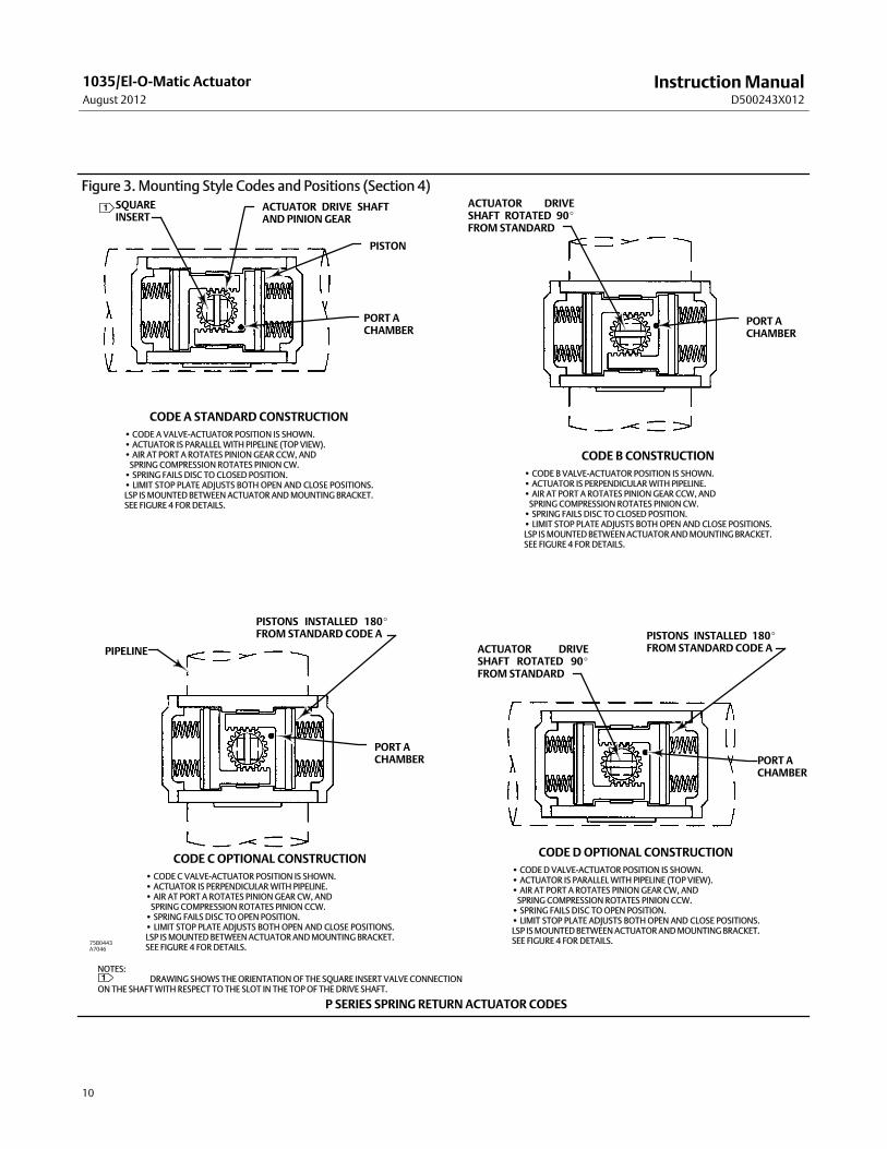
Figure 3. Mounting Style Codes and Positions (Section 4)
P SERIES SPRING RETURN ACTUATOR CODES
CODE A STANDARD CONSTRUCTION•CODE A VALVE-ACTUATOR POSITION IS SHOWN.• ACTUATOR IS PARALLELWITH PIPELINE (TOP VIEW).• AIR AT PORT A ROTATES PINION GEAR CCW, ANDSPRING COMPRESSION ROTATES PINION CW.• SPRING FAILS DISC TO CLOSED POSITION.• LIMIT STOP PLATE ADJUSTS BOTH OPEN AND CLOSE POSITIONS.LSP ISMOUNTED BETWEEN ACTUATOR ANDMOUNTING BRACKET.SEE FIGURE 4 FOR DETAILS.
CODE DOPTIONAL CONSTRUCTION• CODE D VALVE-ACTUATOR POSITION IS SHOWN.• ACTUATOR IS PARALLELWITH PIPELINE (TOP VIEW).• AIR AT PORT A ROTATES PINIONGEAR CW, ANDSPRING COMPRESSION ROTATES PINION CCW.• SPRING FAILS DISC TOOPEN POSITION.• LIMIT STOP PLATE ADJUSTS BOTH OPEN AND CLOSE POSITIONS.LSP ISMOUNTEDBETWEENACTUATORANDMOUNTINGBRACKET.SEE FIGURE 4 FOR DETAILS.
CODE C OPTIONAL CONSTRUCTION• CODE C VALVE-ACTUATOR POSITION IS SHOWN.• ACTUATOR IS PERPENDICULARWITH PIPELINE.• AIR AT PORT A ROTATES PINION GEAR CW, ANDSPRING COMPRESSION ROTATES PINION CCW.• SPRING FAILS DISC TOOPEN POSITION.• LIMIT STOP PLATE ADJUSTS BOTH OPEN AND CLOSE POSITIONS.LSP ISMOUNTED BETWEENACTUATORANDMOUNTINGBRACKET.SEE FIGURE 4 FOR DETAILS.
CODE B CONSTRUCTION• CODE B VALVE-ACTUATOR POSITION IS SHOWN.• ACTUATOR IS PERPENDICULARWITH PIPELINE.• AIR AT PORT A ROTATES PINIONGEAR CCW, ANDSPRING COMPRESSION ROTATES PINION CW.• SPRING FAILS DISC TO CLOSED POSITION.• LIMIT STOP PLATE ADJUSTS BOTH OPEN AND CLOSE POSITIONS.LSP ISMOUNTEDBETWEENACTUATORANDMOUNTINGBRACKET.SEE FIGURE 4 FOR DETAILS.
PORT ACHAMBER
SQUAREINSERT
PORT ACHAMBER
ACTUATOR DRIVE SHAFTAND PINION GEAR
PISTON
PISTONS INSTALLED 180_FROM STANDARD CODE A
PORT ACHAMBER
PISTONS INSTALLED 180_FROM STANDARD CODE AACTUATOR DRIVE
SHAFT ROTATED 90_FROM STANDARD
PIPELINE
PORT ACHAMBER
ACTUATOR DRIVESHAFT ROTATED 90_FROM STANDARD
1
NOTES:DRAWING SHOWS THE ORIENTATION OF THE SQUARE INSERT VALVE CONNECTION
ON THE SHAFTWITH RESPECT TO THE SLOT IN THE TOPOF THE DRIVE SHAFT.1
75B0443A7046
InstructionManualD500243X012
1035/El-O-Matic ActuatorAugust 2012
11
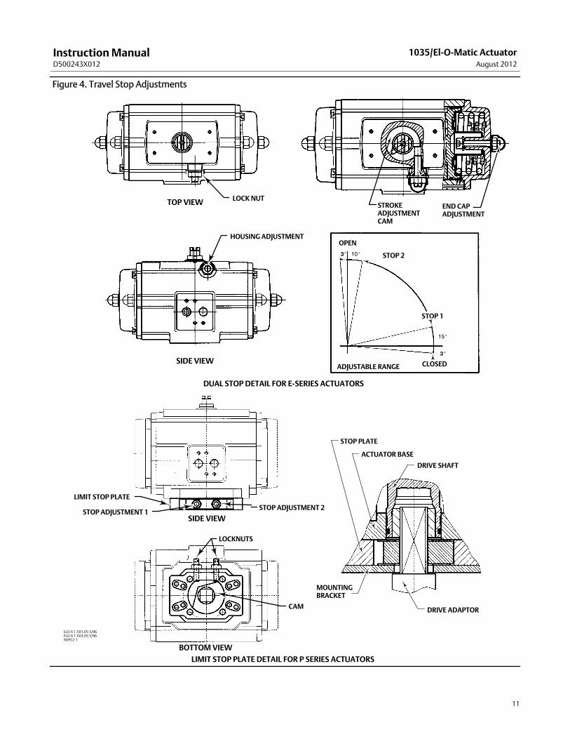
Figure 4. Travel Stop Adjustments
LOCKNUTTOP VIEW
LIMIT STOP PLATE DETAIL FOR P SERIES ACTUATORS
OPEN
STOP 2
STOP 1
3_ 10_
3_
15_
CLOSEDADJUSTABLE RANGE
STROKEADJUSTMENTCAM
END CAPADJUSTMENT
HOUSING ADJUSTMENT
SIDE VIEW
DUAL STOP DETAIL FOR E-SERIES ACTUATORS
ELO A 1.501.05 5/96ELO A 1.503.05 5/96A6952-1
STOP PLATE
ACTUATOR BASE
DRIVE SHAFT
DRIVE ADAPTOR
MOUNTINGBRACKET
LIMIT STOP PLATE
STOP ADJUSTMENT 2STOP ADJUSTMENT 1
LOCKNUTS
CAM
SIDE VIEW
BOTTOMVIEW
InstructionManualD500243X012
1035/El-O-Matic ActuatorAugust 2012
12
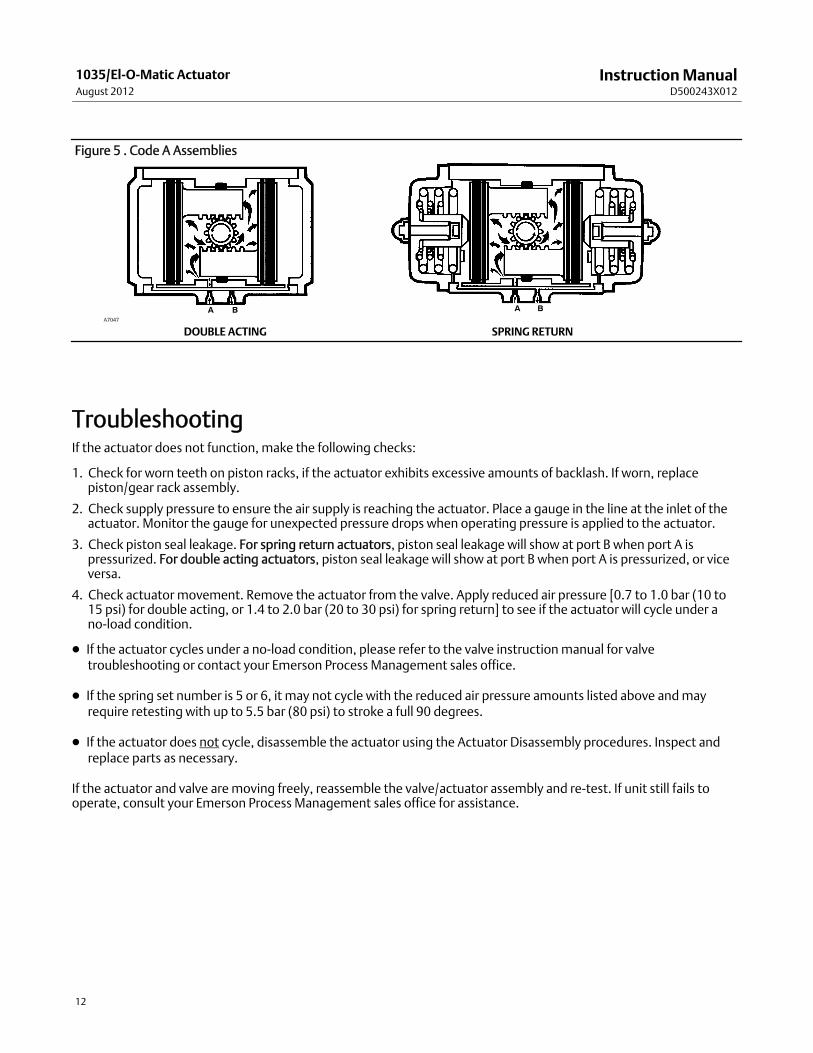
Figure 5 . Code A Assemblies
A BA B
DOUBLE ACTING SPRING RETURNA7047
TroubleshootingIf the actuator does not function, make the following checks:
1. Check for worn teeth on piston racks, if the actuator exhibits excessive amounts of backlash. If worn, replacepiston/gear rack assembly.
2. Check supply pressure to ensure the air supply is reaching the actuator. Place a gauge in the line at the inlet of theactuator. Monitor the gauge for unexpected pressure drops when operating pressure is applied to the actuator.
3. Check piston seal leakage. For spring return actuators, piston seal leakage will show at port B when port A ispressurized. For double acting actuators, piston seal leakage will show at port B when port A is pressurized, or viceversa.
4. Check actuator movement. Remove the actuator from the valve. Apply reduced air pressure [0.7 to 1.0 bar (10 to15 psi) for double acting, or 1.4 to 2.0 bar (20 to 30 psi) for spring return] to see if the actuator will cycle under ano-load condition.
D If the actuator cycles under a no-load condition, please refer to the valve instructionmanual for valvetroubleshooting or contact your Emerson Process Management sales office.
D If the spring set number is 5 or 6, it may not cycle with the reduced air pressure amounts listed above andmayrequire retesting with up to 5.5 bar (80 psi) to stroke a full 90 degrees.
D If the actuator does not cycle, disassemble the actuator using the Actuator Disassembly procedures. Inspect andreplace parts as necessary.
If the actuator and valve aremoving freely, reassemble the valve/actuator assembly and re-test. If unit still fails tooperate, consult your Emerson Process Management sales office for assistance.
InstructionManualD500243X012
1035/El-O-Matic ActuatorAugust 2012
13
MaintenanceActuators parts are subject to normal wear andmust be inspected and replaced as necessary. The frequency ofinspection and replacement depends upon the severity of service conditions. Instructions are given in subsequentsections for disassembly and assembly of the actuator and for inspecting the actuator parts.
WARNING
Avoid personal injury from sudden release of process pressure. Before performing anymaintenance operations:
D Do not remove the actuator from the valvewhile the valve is still pressurized.
D Always wear protective gloves, clothing, and eyewearwhen performing anymaintenance operations to avoid personalinjury.
D Disconnect any operating lines providing air pressure, or a control signal to the actuator. Be sure the actuator cannotsuddenly open or close the valve duringmaintenance.
D Use bypass valves or completely shut off the process pressure. Relieve process pressure on both sides of the valve. Drainthe process media from both sides of the valve.
D Vent the power actuator loading pressure and relieve any actuator spring precompression.
D Use lock-out procedures to be sure that the abovemeasures stay in effect while you arework on the equipment.
D The valve packing areamay contain process fluids that are pressurized, even when the valve has been removed from thepipeline. Process fluids may spray out under pressurewhen removing the packing hardware or packing rings.
D Checkwith your process or safety engineer for any additional measures thatmust be taken to protect against processmedia.
Actuator DisassemblyRemove the actuator from the valve, and remove any other auxiliary equipment from the actuator. (Note the positionsof themounting bracket and accessories for re-assembly). Steps explaining the disassembly and assembly of partsapply to both ends of the actuator. If necessary, refer to the valve instructionmanual for removing and replacing thevalve in the pipeline.
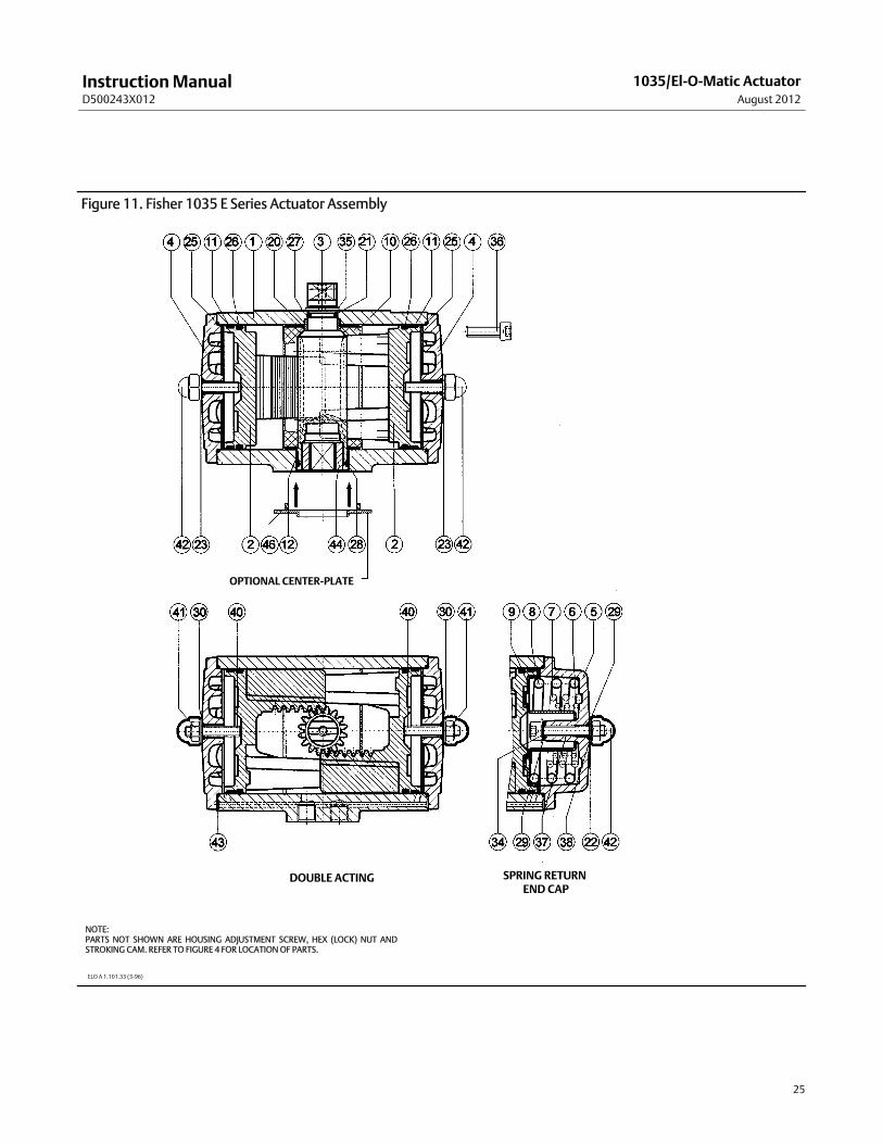
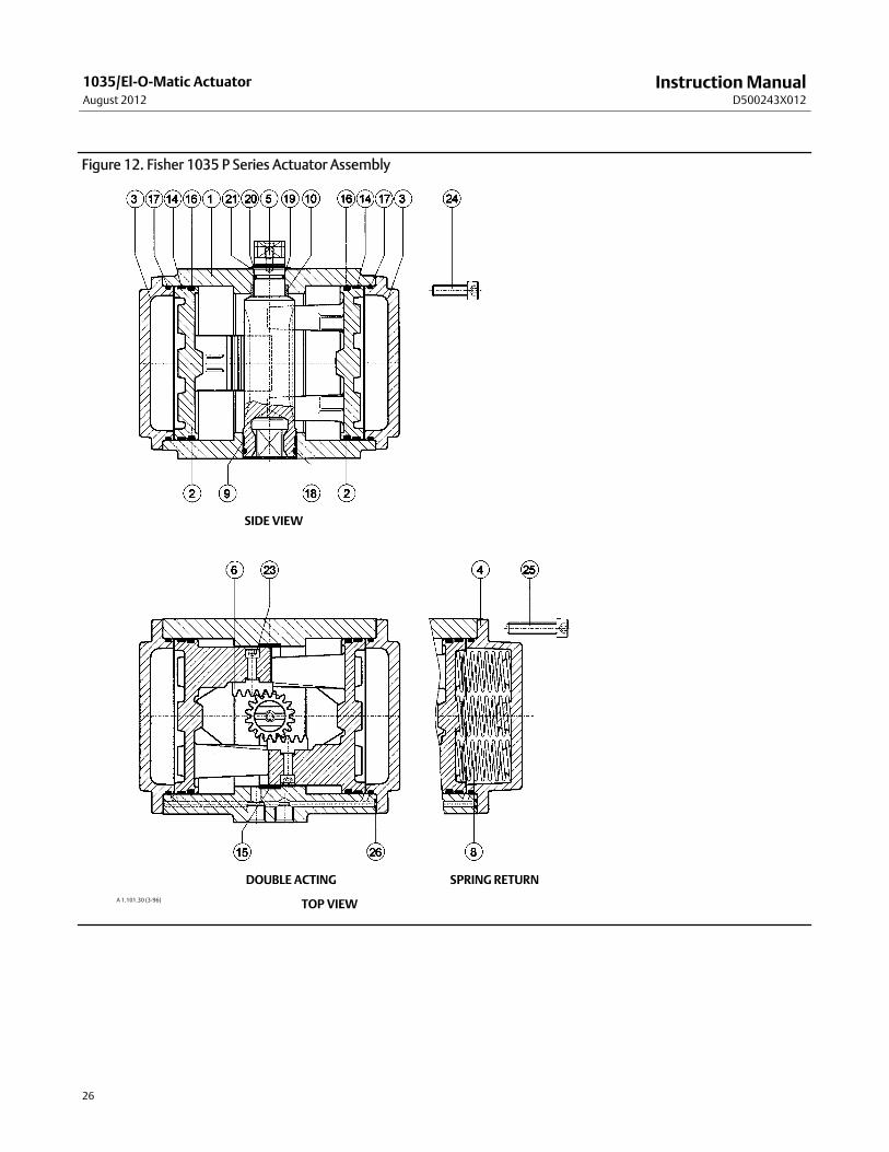
Key numbers are shown in figure 11 for E Series, and figure 12 for P Series actuators, unless otherwise noted.
CAUTION
Butterfly valvesmust be in the closed position before attempting to remove them from the pipeline. The valve disc can bedamaged if the disc is notmoved to the closed position.
1. Remove the actuatormounting bracket and any accessories.
2. When removing the actuator end caps, carefully follow the steps below.
Operationally check the actuator to ensure that the pistons aremoved all the way to the center (towards the driveshaft), before removing the actuator end caps. Use the indexmark on the top of the drive shaft (see figure 4).
a. For Double Acting E and P Series Actuators: Remove socket head screws from both end caps with ametric hexkey. After the screws are removed, gently pry off each end cap. Be careful not to damage the end cap sealingsurfaces.
InstructionManualD500243X012
1035/El-O-Matic ActuatorAugust 2012
14
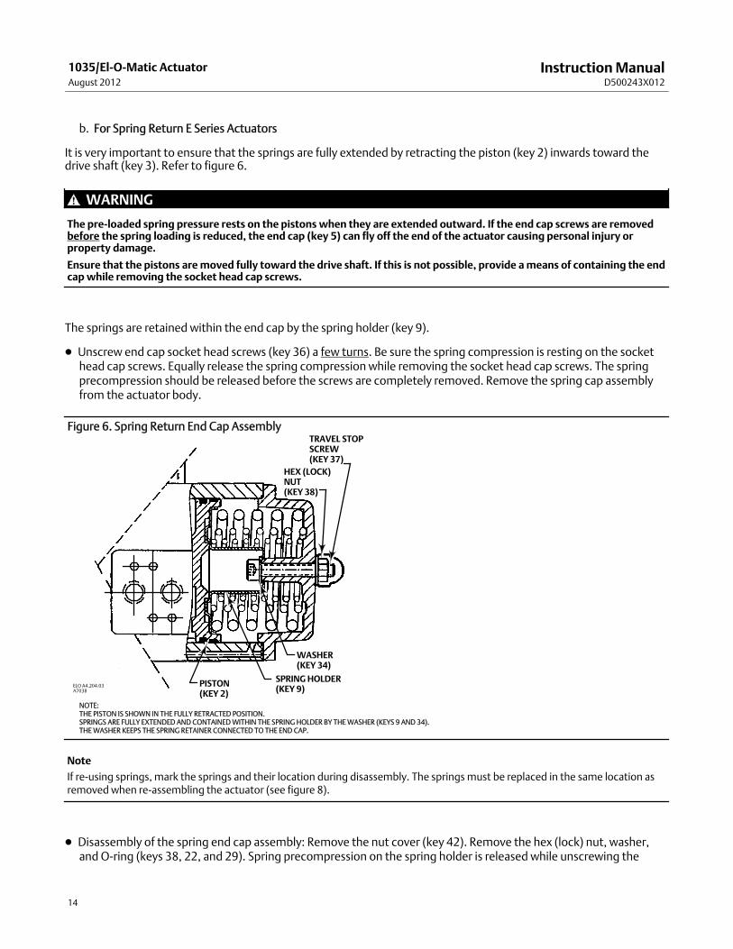
b. For Spring Return E Series Actuators
It is very important to ensure that the springs are fully extended by retracting the piston (key 2) inwards toward thedrive shaft (key 3). Refer to figure 6.
WARNING
The pre-loaded spring pressure rests on the pistons when they are extended outward. If the end cap screws are removedbefore the spring loading is reduced, the end cap (key 5) can fly off the end of the actuator causing personal injury orproperty damage.
Ensure that the pistons aremoved fully toward the drive shaft. If this is not possible, provide ameans of containing the endcapwhile removing the socket head cap screws.
The springs are retained within the end cap by the spring holder (key 9).
D Unscrew end cap socket head screws (key 36) a few turns. Be sure the spring compression is resting on the sockethead cap screws. Equally release the spring compression while removing the socket head cap screws. The springprecompression should be released before the screws are completely removed. Remove the spring cap assemblyfrom the actuator body.
Figure 6. Spring Return End Cap Assembly
NOTE:THE PISTON IS SHOWN IN THE FULLY RETRACTED POSITION.SPRINGS ARE FULLY EXTENDED AND CONTAINEDWITHIN THE SPRING HOLDER BY THEWASHER (KEYS 9 AND 34).THEWASHER KEEPS THE SPRING RETAINER CONNECTED TO THE END CAP.
TRAVEL STOPSCREW(KEY 37)
HEX (LOCK)NUT(KEY 38)
WASHER(KEY 34)
SPRING HOLDER(KEY 9)
PISTON(KEY 2)
ELO A4.204.03A7038
Note
If re-using springs, mark the springs and their location during disassembly. The springsmust be replaced in the same location asremoved when re-assembling the actuator (see figure 8).
D Disassembly of the spring end cap assembly: Remove the nut cover (key 42). Remove the hex (lock) nut, washer,and O-ring (keys 38, 22, and 29). Spring precompression on the spring holder is released while unscrewing the
InstructionManualD500243X012
1035/El-O-Matic ActuatorAugust 2012
15
travel stop screw (key 37). When the travel stop screw (key 37) is removed from the end cap assembly, it will releasethe spring clip, washer (key 34), and spring(s) (key 9, 34, and 6, 7, and 8 if used). If reusing springs, return them tothe same location as removed. If replacing springs, replace all the springs in both end caps.
c. For Spring Return P Series Actuators
It is very important to ensure that the springs are fully extended by retracting the piston (key 2) inwards toward thedrive shaft (key 3).
Operationally check the actuator to ensure that the pistons aremoved all the way to the center (towards the driveshaft), before removing the socket head cap screws (key 25, figure 12). Read the steps in this sub-section beforeremoving the end cap screws (key 25).
WARNING
The pre-loaded spring pressure rests on the pistons when they are extended outward. If the end cap screws are removedbefore the spring loading is reduced, the end cap (key 5) can fly off the end of the actuator causing personal injury orproperty damage.
Ensure that the pistons aremoved fully toward the drive shaft. If this is not possible, provide ameans of containing the endcapwhile removing the socket head cap screws.
D The springs are in-between the end cap and piston. Be careful when removing the end cap as the springsmay fallout of the body or end cap. If reusing the springs, re-install them in the same position as removed.
D On a flat working surface, block-up the actuator so it is vertical to avoid the springs falling out of the actuator whileremoving the end cap. Repeat on both ends of the actuator.
Note
If re-using springs, mark the springs and their location during disassembly. The springsmust be replaced in the same location asremoved when re-assembling the actuator (see figure 9).
D Unscrew end cap socket head screws (key 25) a few turns. Be sure the spring compression is resting on the sockethead cap screws. Equally release the spring compression while removing the socket head cap screws. The springprecompression should be released before the screws are completely removed. Remove the spring cap assemblyfrom the actuator body.
3. Clean, inspect, and/or obtain replacement parts. When reassembling the actuator, replace all soft parts provided inthe Parts Kits listed at the end of this manual.
4. Remove the adjustable travel stop/ housing adjustment (see figure 4).
5. Removing the Pistons: The two pistons (key 2) can now be removed by rotating the drive shaft, moving the pistonassemblies outward until the pinion gear has released them.
The gear rack in E Series actuators is machined into the piston, and so does not have to be removed separately. If thegear rack is damaged, replace both pistons.
Removing the Drive Shaft1. Remove the spring clip (E Series key 35, P Series key 20) with a pin spanner. Use caution, as the spring clip is under agreat deal of tension. Also, remove the E Series washers (keys 27 and 21) or P Series washer and O-ring (keys 21 and19) from the shaft.
InstructionManualD500243X012
1035/El-O-Matic ActuatorAugust 2012
16
2. Remove the drive shaft (E Series key 3, P Series key 5, figures 11 and 12) through the bottom of the actuator.
3. For P Series actuators: remove the Piston Gear Rack. The gear rack in the P Series actuators is a separate part (key 6)and is held in place with a socket head cap screw (key 22). Both gear racks can be removed and replaced byremoving them from the pistons.
4. Ensure that all actuator parts are clean and ready for assembly. Inspect the actuator body and component parts forwear or scratches. If the inside wall of the body is scored the actuator will leak. Light traces of scoring, barelydetectable to the touch, are acceptable. Obtain replacement parts from your Emerson Process Management salesoffice.
Actuator Assembly
Repair KitsRepair kits are available for re-assembly. The large repair kit provides O-rings, guide bands, bushings, and bearings.The small kit provides a set of soft parts only for the actuator. Repair kits are available for standard, low temperature,and high temperature actuators. Refer to the Repair Kits table at the end of this manual.
LubricationRefer to the Specifications table for temperature ranges.
Standard and High Temperature Actuator: Lubricate the actuator moderately with a complex calcium sulphonategrease suitable for the application's temperature range. Use the Parts Kit for the appropriate temperature application.
Low Temperature Actuator: Lubricate the actuator moderately with low temperature silicone grease. Use the Parts Kitfor standard and low temperature applications.
Lubricate the actuator moderately with an appropriate grease. Apply a light film of grease to all O-rings, gear racks,bearings, bushings, and guide bands. In the following steps, lubricate all moving parts during re-assembly.
Installing the Drive ShaftE Series actuators: Some constructions use a Dual Stop arrangement. The housing adjustment screw is used with a pinlocated in the drive shaft, and a stroking adjustment cammounted on the shaft for the stop. Ensure the cam is alignedcorrectly with respect to the housing adjustment screw. Use figure 4 as a guide for alignment.
1. Replace the top and bottom shaft bearings (keys 20 and 12) in the actuator body.
2. Insert the adjustment screw, if applicable, and thread it into the body a few turns, and hand tighten the hex nut. Theadjustment screw should be loose enough to allow full travel of the cam and pistons.
3. Place the cam (see figure 4) on the small end of the drive shaft. Position the cam on the shaft so the pin is located inthe open section of the cam.
4. Install the O-rings and guide bushing on the drive shaft. The guide bushingmay have to be cleaned of grease, rolledtightly around the drive shaft and held in place while inserting into the actuator housing.
CAUTION
When inserting the drive shaft, be sure to keep the O-Rings from becoming trapped and damaged between the pinion andthe actuator body. To verify the condition of the O-Rings at the end of the installation, cycle the actuator 5 times and run asoap bubble test on the seal on both the top and bottom of the drive shaft.
InstructionManualD500243X012
1035/El-O-Matic ActuatorAugust 2012
17
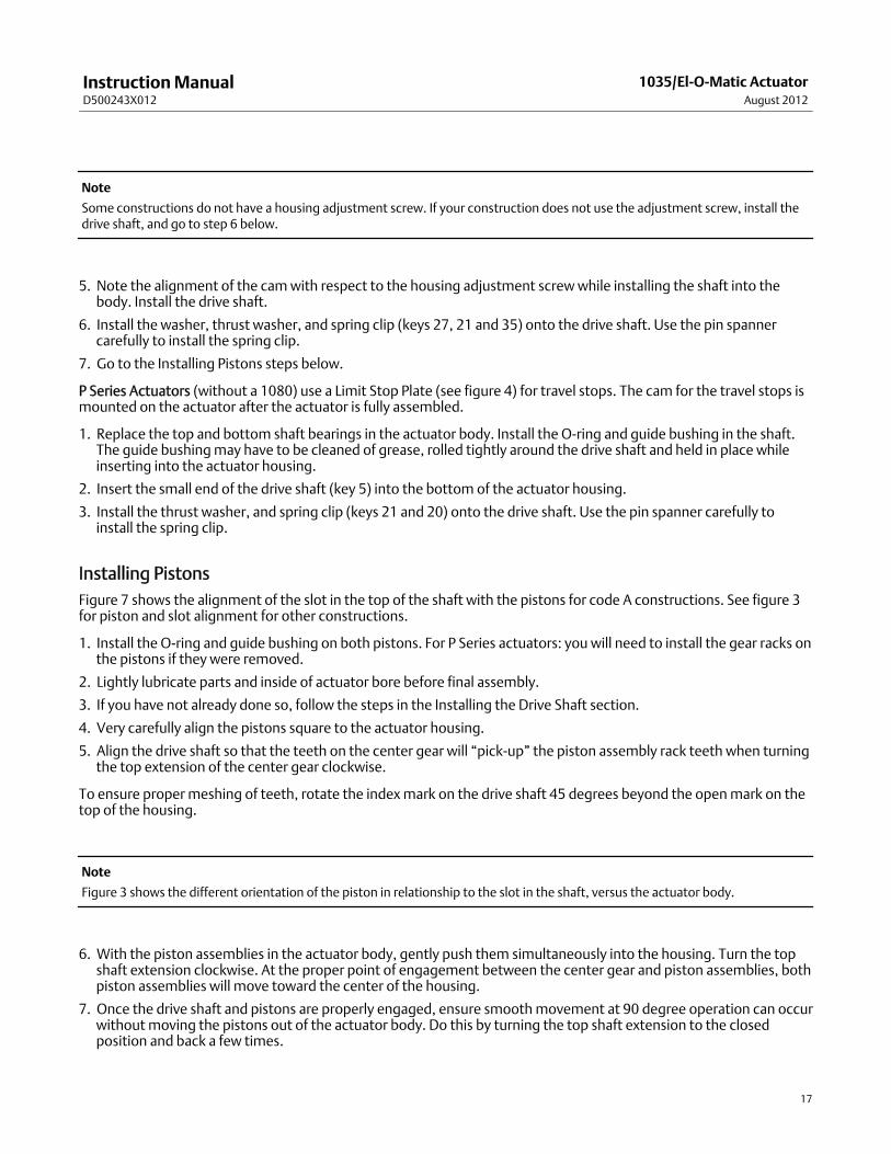
Note
Some constructions do not have a housing adjustment screw. If your construction does not use the adjustment screw, install thedrive shaft, and go to step 6 below.
5. Note the alignment of the camwith respect to the housing adjustment screwwhile installing the shaft into thebody. Install the drive shaft.
6. Install the washer, thrust washer, and spring clip (keys 27, 21 and 35) onto the drive shaft. Use the pin spannercarefully to install the spring clip.
7. Go to the Installing Pistons steps below.
P Series Actuators (without a 1080) use a Limit Stop Plate (see figure 4) for travel stops. The cam for the travel stops ismounted on the actuator after the actuator is fully assembled.
1. Replace the top and bottom shaft bearings in the actuator body. Install the O-ring and guide bushing in the shaft.The guide bushingmay have to be cleaned of grease, rolled tightly around the drive shaft and held in place whileinserting into the actuator housing.
2. Insert the small end of the drive shaft (key 5) into the bottom of the actuator housing.
3. Install the thrust washer, and spring clip (keys 21 and 20) onto the drive shaft. Use the pin spanner carefully toinstall the spring clip.
Installing PistonsFigure 7 shows the alignment of the slot in the top of the shaft with the pistons for code A constructions. See figure 3for piston and slot alignment for other constructions.
1. Install the O-ring and guide bushing on both pistons. For P Series actuators: you will need to install the gear racks onthe pistons if they were removed.
2. Lightly lubricate parts and inside of actuator bore before final assembly.
3. If you have not already done so, follow the steps in the Installing the Drive Shaft section.
4. Very carefully align the pistons square to the actuator housing.
5. Align the drive shaft so that the teeth on the center gear will “pick-up” the piston assembly rack teeth when turningthe top extension of the center gear clockwise.
To ensure proper meshing of teeth, rotate the indexmark on the drive shaft 45 degrees beyond the openmark on thetop of the housing.
Note
Figure 3 shows the different orientation of the piston in relationship to the slot in the shaft, versus the actuator body.
6. With the piston assemblies in the actuator body, gently push them simultaneously into the housing. Turn the topshaft extension clockwise. At the proper point of engagement between the center gear and piston assemblies, bothpiston assemblies will move toward the center of the housing.
7. Once the drive shaft and pistons are properly engaged, ensure smoothmovement at 90 degree operation can occurwithoutmoving the pistons out of the actuator body. Do this by turning the top shaft extension to the closedposition and back a few times.
InstructionManualD500243X012
1035/El-O-Matic ActuatorAugust 2012
18
8. If not already done, replace the washer over the top shaft extension. Install the spring clip onto themating grooveon the top shaft extension with a pin spanner.
9. Replace the actuator end caps taking care to properly seal themwith O-rings. Use themetric hex keys to replace thesocket head screws.
10. The adjustment screw and nut, if applicable, should now be set to stop travel at the desired position.
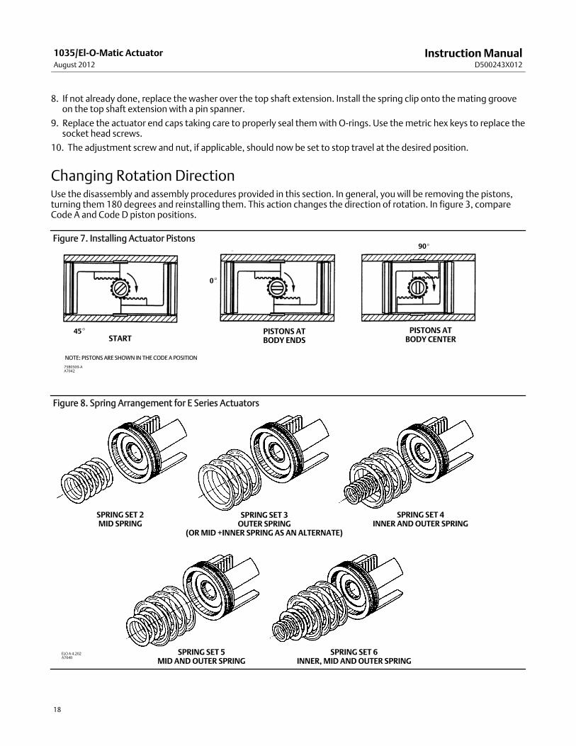
Changing Rotation DirectionUse the disassembly and assembly procedures provided in this section. In general, you will be removing the pistons,turning them 180 degrees and reinstalling them. This action changes the direction of rotation. In figure 3, compareCode A and Code D piston positions.
Figure 7. Installing Actuator Pistons
NOTE: PISTONS ARE SHOWN IN THE CODE A POSITION
STARTPISTONS ATBODY ENDS
PISTONS ATBODY CENTER
45_
0_
90_
75B0509-AA7042
Figure 8. Spring Arrangement for E Series Actuators
SPRING SET 2MID SPRING
SPRING SET 3OUTER SPRING
(ORMID +INNER SPRING AS AN ALTERNATE)
SPRING SET 4INNER ANDOUTER SPRING
SPRING SET 5MID ANDOUTER SPRING
SPRING SET 6INNER,MID ANDOUTER SPRING
ELO A 4.202A7040
InstructionManualD500243X012
1035/El-O-Matic ActuatorAugust 2012
19
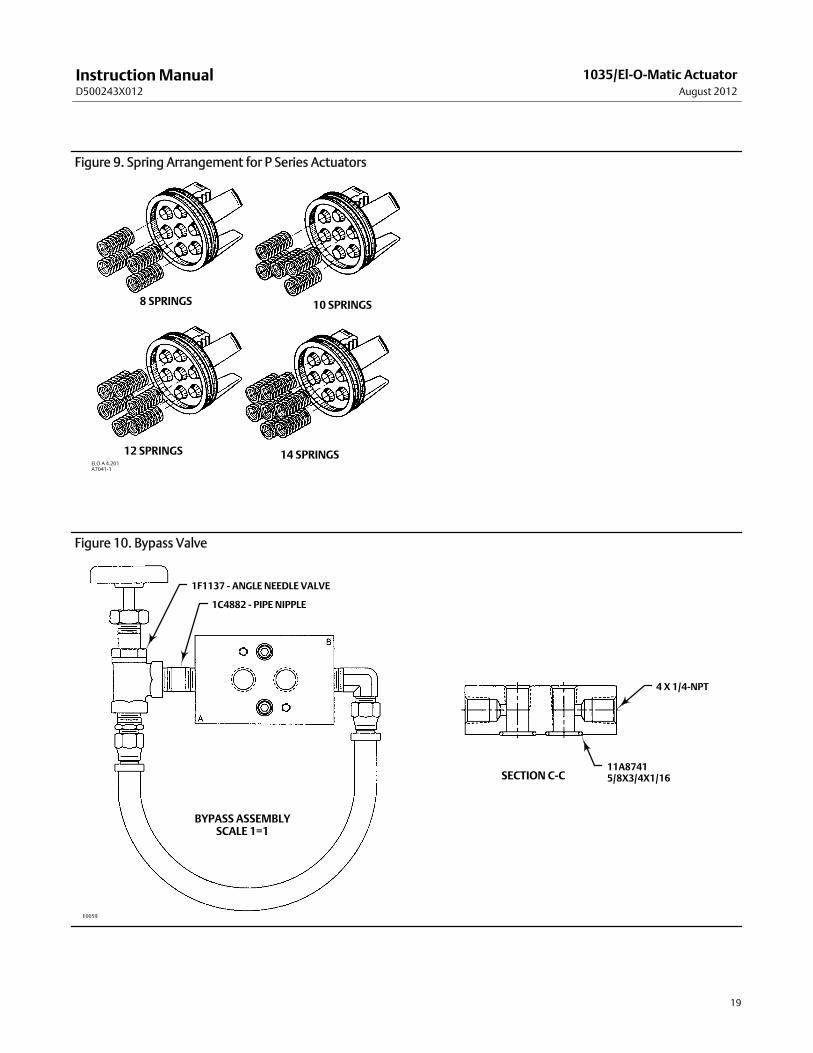
Figure 9. Spring Arrangement for P Series Actuators
ELO A 4.201A7041-1
8 SPRINGS
14 SPRINGS12 SPRINGS
10 SPRINGS
Figure 10. Bypass Valve
1F1137 - ANGLE NEEDLE VALVE
1C4882 - PIPE NIPPLE
4 X 1/4-NPT
11A87415/8X3/4X1/16
BYPASS ASSEMBLYSCALE 1=1
SECTION C-C
E0059
InstructionManualD500243X012
1035/El-O-Matic ActuatorAugust 2012
20
Spring Return E Series ActuatorsSpring return E Series actuators use from two to amaximum of six springs. One, two, or three springs are inserted intoeach end cap (see figure 8). Refer to the nameplate to verify the number of springs required.
Each end cap spring pack incorporates a travel stop adjustment screw (key 37). This may be used to adjust the end ofthe stroke for valve seating in either the “fail open” or “fail closed” arrangements.
1. When installing used springs in a spring return actuator, ensure that the springs are replaced in the identicalposition fromwhich they were removed.
2. If a spring return actuator is being repaired due to spring failure, replace all the springs in the actuator.
3. To assemble the spring assembly, install the spring(s) into the end cap. Be sure that all springs are seated correctlyin the end cap (key 5) and in the spring holder (key 9). Place the spring holder and washer on top of the springs, andinstall the adjustment screw (keys 34 and 37).
4. Place the end cap bolts through the retention holes of the end cap. If converting a double acting unit to a springreturn unit, be sure to use new end cap screws (key 25, figure 12).
5. Engage the bolts with the tapped holes in the actuator body by forcing down slightly on the cap. Tighten each boltin small, equal amount of turns, compressing the springs equally.
Spring Return P Series ActuatorsSpring return actuators use from four to amaximum of fourteen springs. One through seven springs are inserted intoeach end cap (see figure 9). Refer to the nameplate to verify the number of springs required.
1. When installing used springs in a spring return actuator, ensure that the springs are replaced in their identicalposition in the end cap fromwhere they were removed.
NoteWhen less than the standard number of seven springs are used in each end cap, the springs should be positioned as shown infigure 9.
2. If a spring return actuator is being repaired due to a failed spring, replace all the springs in the actuator.
3. Ensure that the pistons are stroked fully inward, towards the center of the actuator (this may be done by rotatingthe actuator shaft with a wrench).
4. When replacing the springs in a P Series spring-return actuator, position the actuator so that it stands on one end.
5. Place the springs on the piston face, engaging themwith the alignment nibs cast into the piston.
6. Place the end cap over the springs. Align themwith the corresponding nibs which are cast into the end cap.
7. If converting a double acting unit to a spring return unit, be sure to use new end cap screws (key 25, figure 12).Install the end cap screws.
8. Engage the screws with the tapped holes in the actuator body by forcing down slightly on the cap. Tighten eachbolt in small, equal amount of turns, compressing the springs equally.
Installing the Bypass ValveThe optional bypass valve should be used when pressure needs to be stabilized between port A and port B (see figure10). The following steps provide installation of the bypass valve. Removing the bypass valve simply requiresperforming these steps in the reverse order.
InstructionManualD500243X012
1035/El-O-Matic ActuatorAugust 2012
21
1. Position the O-rings between the bypass block and the Namurmounting area. Attach the screws through thebypass block to the Namurmounting area.
2. Attach the tubing to the fittings.
3. Attach the angle needle valve and the bypass block to the tubing.
4. Pressure the ports and check for leakage. Check the pressure to both ports A and B.
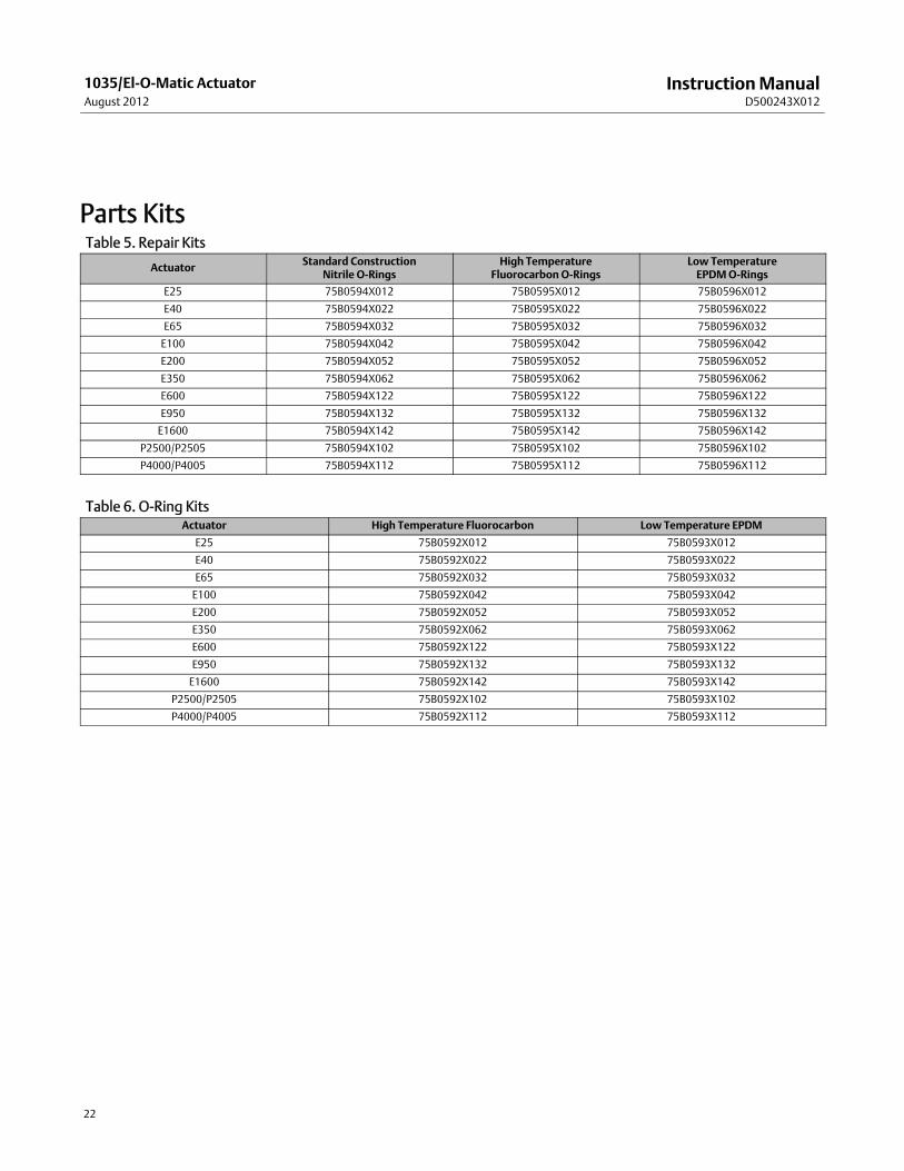
Parts OrderingTwo types of kits are available. The repair kits provide O-rings and guide bushing/bearings, and the O-ring kit providesthe O-rings only. Refer to tables 5 and 6 for kit numbers.
WARNING
Use only genuine Fisher replacement parts. Components that are not supplied by Emerson Process Management shouldnot, under any circumstances, be used in any Fisher valve, because theymay void your warranty, might adversely affect theperformance of the valve, and could cause personal injury and property damage.
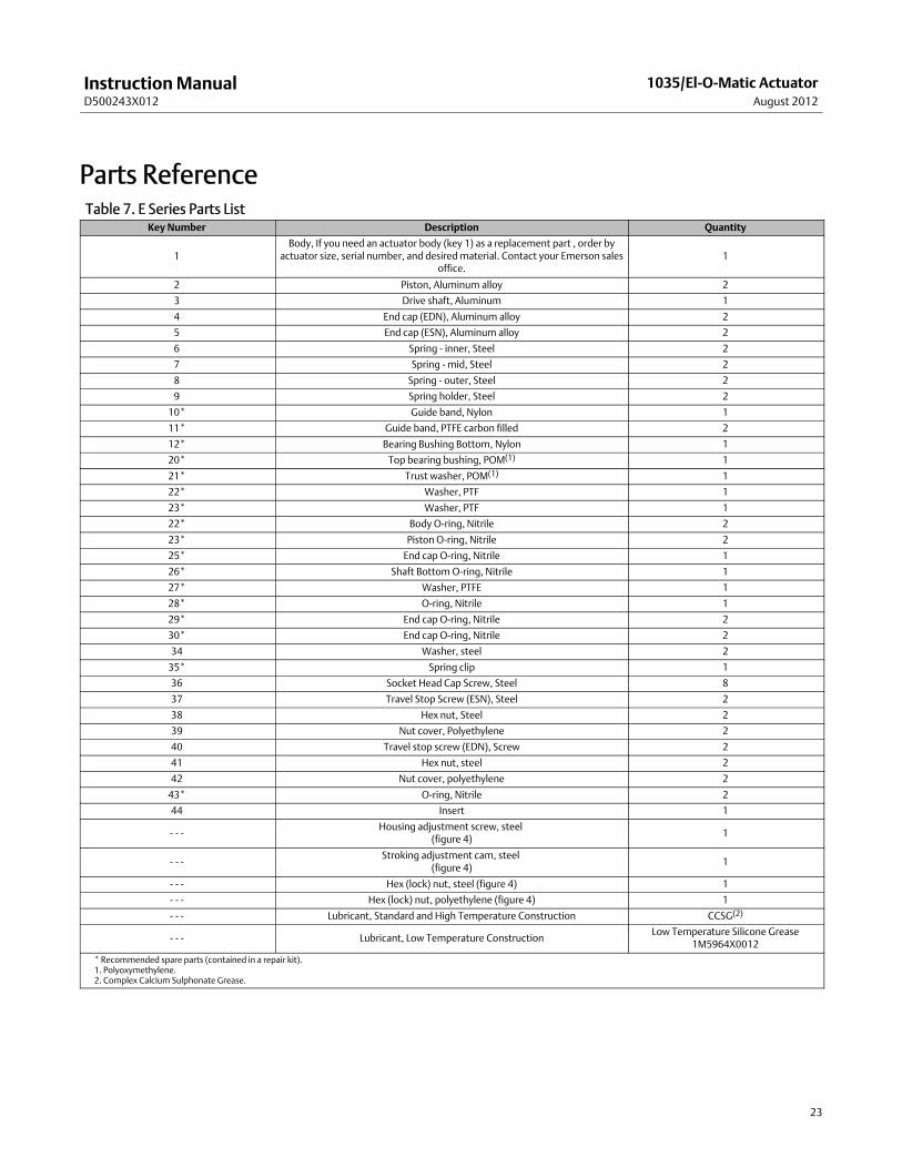
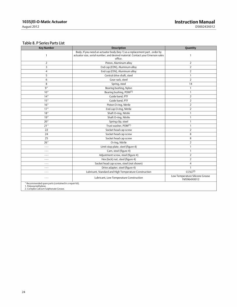
Key numbers and part descriptions are shown in tables 7 and 8.
Recommended spare parts aremarked with an asterisk (*) following the key number.
Typical actuator assemblies are shown in figures 11 and 12.
When corresponding with your Emerson Process Management sales office, please identify the Actuator as a Fisher1035 and provide the actuator serial number located on the nameplate.
InstructionManualD500243X012
1035/El-O-Matic ActuatorAugust 2012
22
Parts KitsTable 5. Repair Kits
Actuator Standard ConstructionNitrile O-Rings
High TemperatureFluorocarbonO-Rings
Low TemperatureEPDMO-Rings
E25 75B0594X012 75B0595X012 75B0596X012
E40 75B0594X022 75B0595X022 75B0596X022
E65 75B0594X032 75B0595X032 75B0596X032
E100 75B0594X042 75B0595X042 75B0596X042
E200 75B0594X052 75B0595X052 75B0596X052
E350 75B0594X062 75B0595X062 75B0596X062
E600 75B0594X122 75B0595X122 75B0596X122
E950 75B0594X132 75B0595X132 75B0596X132
E1600 75B0594X142 75B0595X142 75B0596X142
P2500/P2505 75B0594X102 75B0595X102 75B0596X102
P4000/P4005 75B0594X112 75B0595X112 75B0596X112
Table 6. O-Ring KitsActuator High Temperature Fluorocarbon Low Temperature EPDM
E25 75B0592X012 75B0593X012
E40 75B0592X022 75B0593X022
E65 75B0592X032 75B0593X032
E100 75B0592X042 75B0593X042
E200 75B0592X052 75B0593X052
E350 75B0592X062 75B0593X062
E600 75B0592X122 75B0593X122
E950 75B0592X132 75B0593X132
E1600 75B0592X142 75B0593X142
P2500/P2505 75B0592X102 75B0593X102
P4000/P4005 75B0592X112 75B0593X112
InstructionManualD500243X012
1035/El-O-Matic ActuatorAugust 2012
23
Parts ReferenceTable 7. E Series Parts List
Key Number Description Quantity
1Body, If you need an actuator body (key 1) as a replacement part , order by
actuator size, serial number, and desiredmaterial. Contact your Emerson salesoffice.
1
2 Piston, Aluminum alloy 2
3 Drive shaft, Aluminum 1
4 End cap (EDN), Aluminum alloy 2
5 End cap (ESN), Aluminum alloy 2
6 Spring - inner, Steel 2
7 Spring - mid, Steel 2
8 Spring - outer, Steel 2
9 Spring holder, Steel 2
10* Guide band, Nylon 1
11* Guide band, PTFE carbon filled 2
12* Bearing Bushing Bottom, Nylon 1
20* Top bearing bushing, POM(1) 1
21* Trust washer, POM(1) 1
22* Washer, PTF 1
23* Washer, PTF 1
22* Body O-ring, Nitrile 2
23* Piston O-ring, Nitrile 2
25* End cap O-ring, Nitrile 1
26* Shaft BottomO-ring, Nitrile 1
27* Washer, PTFE 1
28* O-ring, Nitrile 1
29* End cap O-ring, Nitrile 2
30* End cap O-ring, Nitrile 2
34 Washer, steel 2
35* Spring clip 1
36 Socket Head Cap Screw, Steel 8
37 Travel Stop Screw (ESN), Steel 2
38 Hex nut, Steel 2
39 Nut cover, Polyethylene 2
40 Travel stop screw (EDN), Screw 2
41 Hex nut, steel 2
42 Nut cover, polyethylene 2
43* O-ring, Nitrile 2
44 Insert 1
- - -Housing adjustment screw, steel
(figure 4)1
- - -Stroking adjustment cam, steel
(figure 4)1
- - - Hex (lock) nut, steel (figure 4) 1
- - - Hex (lock) nut, polyethylene (figure 4) 1
- - - Lubricant, Standard and High Temperature Construction CCSG(2)
- - - Lubricant, Low Temperature ConstructionLow Temperature Silicone Grease
1M5964X0012* Recommended spare parts (contained in a repair kit).1. Polyoxymethylene.2. Complex Calcium Sulphonate Grease.
InstructionManualD500243X012
1035/El-O-Matic ActuatorAugust 2012
24
Table 8. P Series Parts ListKey Number Description Quantity
1Body, If you need an actuator body (key 1) as a replacement part , order by
actuator size, serial number, and desiredmaterial. Contact your Emerson salesoffice.
1
2 Piston, Aluminum alloy 2
3 End cap (EDN), Aluminum alloy 2
4 End cap (ESN), Aluminum alloy 2
5 Central drive shaft, steel 1
6 Gear rack, steel 2
8 Spring, steel 14
9* Bearing bushing, Nylon 1
10* Bearing bushing, POM(1) 1
14* Guide band, PTF 2
15* Guide band, PTF 2
16* Piston O-ring, Nitrile 2
17* End cap O-ring, Nitrile 2
18* Shaft O-ring, Nitrile 1
19* Shaft O-ring, Nitrile 1
20* Spring clip, steel 1
21* Trust washer, POM(1) 1
22 Socket head cap screw 2
24 Socket head cap screw 8
25 Socket head cap screw 8
26* O-ring, Nitrile 2
- - - Limit stop plate, steel (figure 4) 1
- - - Cam, steel (figure 4) 1
- - - Adjustment screw, steel (figure 4) 2
- - - Hex (lock) nut, steel (figure 4) 2
- - - Socket head cap screw, steel (not shown) 4
- - - Drive adapter, steel (figure 4) 1
- - - Lubricant, Standard and High Temperature Construction CCSG(2)
- - - Lubricant, Low Temperature ConstructionLow Temperature Silicone Grease
1M5964X0012* Recommended spare parts (contained in a repair kit).1. Polyoxymethylene.2. Complex Calcium Sulphonate Grease.
InstructionManualD500243X012
1035/El-O-Matic ActuatorAugust 2012
25
Figure 11. Fisher 1035 E Series Actuator Assembly
ELO A 1.101.33 (3-96)
DOUBLE ACTING SPRING RETURNEND CAP
NOTE:PARTS NOT SHOWN ARE HOUSING ADJUSTMENT SCREW, HEX (LOCK) NUT ANDSTROKING CAM. REFER TO FIGURE 4 FOR LOCATION OF PARTS.
OPTIONAL CENTER-PLATE
InstructionManualD500243X012
1035/El-O-Matic ActuatorAugust 2012
26
Figure 12. Fisher 1035 P Series Actuator Assembly
A1.101.30 (3-96)
SIDE VIEW
DOUBLE ACTING SPRING RETURN
TOP VIEW

InstructionManualD500243X012
1035/El-O-Matic ActuatorAugust 2012
27
InstructionManualD500243X012
1035/El-O-Matic ActuatorAugust 2012
28
Emerson Process ManagementMarshalltown, Iowa 50158 USASorocaba, 18087 BrazilChatham, Kent ME4 4QZUKDubai, United Arab EmiratesSingapore 128461 Singapore
www.Fisher.com
The contents of this publication are presented for informational purposes only, and while every effort has beenmade to ensure their accuracy, they are notto be construed as warranties or guarantees, express or implied, regarding the products or services described herein or their use or applicability. All sales aregoverned by our terms and conditions, which are available upon request. We reserve the right tomodify or improve the designs or specifications of suchproducts at any time without notice.
E 1997, 2012 Fisher Controls International LLC. All rights reserved.
Fisher and POSI-SEAL aremarks owned by one of the companies in the Emerson Process Management business unit of Emerson Electric Co. Emerson ProcessManagement, Emerson, and the Emerson logo are trademarks and servicemarks of Emerson Electric Co. All other marks are the property of their respectiveowners.
Neither Emerson, Emerson Process Management, nor any of their affiliated entities assumes responsibility for the selection, use ormaintenanceof any product. Responsibility for proper selection, use, andmaintenance of any product remains solely with the purchaser and end user.