fisher yd and ys 3-way valves - guest home...
TRANSCRIPT
www.Fisher.com
Fisher� YD and YS 3-Way ValvesContents
Introduction 1. . . . . . . . . . . . . . . . . . . . . . . . . . . . . . .Scope of Manual 1. . . . . . . . . . . . . . . . . . . . . . . . . .Specifications 1. . . . . . . . . . . . . . . . . . . . . . . . . . . .
Installation 2. . . . . . . . . . . . . . . . . . . . . . . . . . . . . . . .Maintenance 3. . . . . . . . . . . . . . . . . . . . . . . . . . . . . .
Packing Lubrication 4. . . . . . . . . . . . . . . . . . . . . . .Packing Maintenance 5. . . . . . . . . . . . . . . . . . . . . .
Packing Replacement 5. . . . . . . . . . . . . . . . . . . .Trim Maintenance 7. . . . . . . . . . . . . . . . . . . . . . . . .
Disassembly 8. . . . . . . . . . . . . . . . . . . . . . . . . . . .Assembly 10. . . . . . . . . . . . . . . . . . . . . . . . . . . . . .
ENVIRO-SEAL� Bellows Seal Bonnet 12. . . . . .Replacing a Plain or Extension Bonnet with an
ENVIRO-SEAL Bellows Seal Bonnet(Stem/Bellows Assembly) 12. . . . . . . . . . . . . .
Replacement of an InstalledENVIRO-SEAL Bellows Seal Bonnet(Stem/Bellows Assembly) 13. . . . . . . . . . . . . .
Purging the ENVIRO-SEALBellows Seal Bonnet 14. . . . . . . . . . . . . . . . . .
Parts Ordering 15. . . . . . . . . . . . . . . . . . . . . . . . . . . .Parts Kits 18. . . . . . . . . . . . . . . . . . . . . . . . . . . . . . . .Parts List 19. . . . . . . . . . . . . . . . . . . . . . . . . . . . . . . .
YD and YS Valve 19. . . . . . . . . . . . . . . . . . . . . . . .Bonnet for YD and YS 23. . . . . . . . . . . . . . . . . . . .
Introduction
Scope of ManualThis instruction manual includes installation,maintenance, and parts information for NPS 1/2through 6 YD and YS control valves. Refer toseparate manuals for instructions covering theactuators and accessories.
Do not install, operate, or maintain YD or YS valveswithout being fully trained and qualified in valve,actuator, and accessory installation, operation, andmaintenance. To avoid personal injury or propertydamage, it is important to carefully read, understand,and follow all the contents of this manual, includingall safety cautions and warnings. If you have any
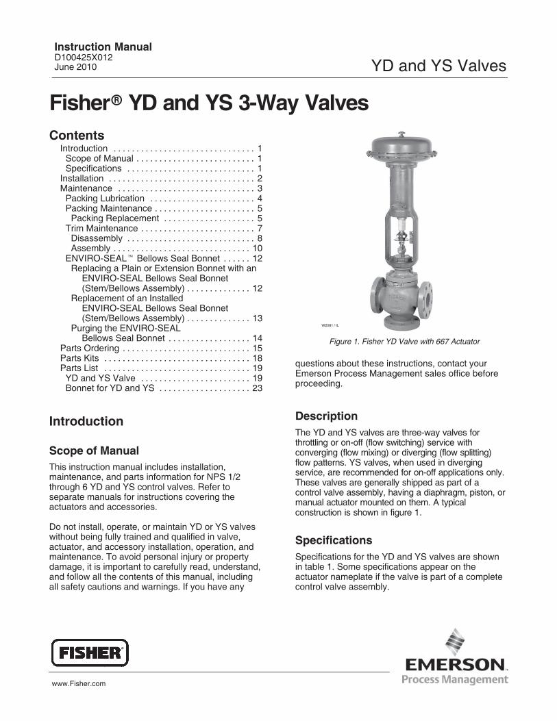
Figure 1. Fisher YD Valve with 667 Actuator
W2081 / IL
questions about these instructions, contact yourEmerson Process Management sales office beforeproceeding.
DescriptionThe YD and YS valves are three-way valves forthrottling or on-off (flow switching) service withconverging (flow mixing) or diverging (flow splitting)flow patterns. YS valves, when used in divergingservice, are recommended for on-off applications only.These valves are generally shipped as part of acontrol valve assembly, having a diaphragm, piston, ormanual actuator mounted on them. A typicalconstruction is shown in figure 1.
SpecificationsSpecifications for the YD and YS valves are shownin table 1. Some specifications appear on theactuator nameplate if the valve is part of a completecontrol valve assembly.
Instruction ManualD100425X012June 2010 YD and YS Valves
YD and YS ValvesInstruction Manual
June 2010
2
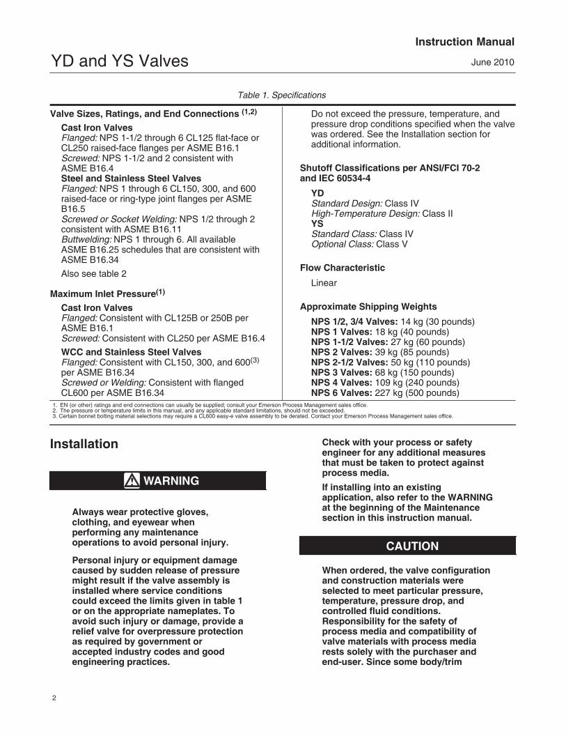
Table 1. Specifications
Valve Sizes, Ratings, and End Connections (1,2)
Cast Iron ValvesFlanged: NPS 1-1/2 through 6 CL125 flat-face orCL250 raised-face flanges per ASME B16.1Screwed: NPS 1-1/2 and 2 consistent with ASME B16.4Steel and Stainless Steel ValvesFlanged: NPS 1 through 6 CL150, 300, and 600raised-face or ring-type joint flanges per ASMEB16.5Screwed or Socket Welding: NPS 1/2 through 2consistent with ASME B16.11Buttwelding: NPS 1 through 6. All available ASME B16.25 schedules that are consistent withASME B16.34
Also see table 2
Maximum Inlet Pressure(1)
Cast Iron ValvesFlanged: Consistent with CL125B or 250B perASME B16.1Screwed: Consistent with CL250 per ASME B16.4
WCC and Stainless Steel ValvesFlanged: Consistent with CL150, 300, and 600(3)
per ASME B16.34Screwed or Welding: Consistent with flangedCL600 per ASME B16.34
Do not exceed the pressure, temperature, andpressure drop conditions specified when the valvewas ordered. See the Installation section foradditional information.
Shutoff Classifications per ANSI/FCI 70-2and IEC 60534-4
YDStandard Design: Class IVHigh-Temperature Design: Class IIYSStandard Class: Class IVOptional Class: Class V
Flow Characteristic
Linear
Approximate Shipping Weights
NPS 1/2, 3/4 Valves: 14 kg (30 pounds)NPS 1 Valves: 18 kg (40 pounds)NPS 1-1/2 Valves: 27 kg (60 pounds)NPS 2 Valves: 39 kg (85 pounds)NPS 2-1/2 Valves: 50 kg (110 pounds)NPS 3 Valves: 68 kg (150 pounds)NPS 4 Valves: 109 kg (240 pounds)NPS 6 Valves: 227 kg (500 pounds)
1. EN (or other) ratings and end connections can usually be supplied; consult your Emerson Process Management sales office.2. The pressure or temperature limits in this manual, and any applicable standard limitations, should not be exceeded.3. Certain bonnet bolting material selections may require a CL600 easy-e valve assembly to be derated. Contact your Emerson Process Management sales office.
Installation
WARNING
Always wear protective gloves,clothing, and eyewear whenperforming any maintenanceoperations to avoid personal injury.
Personal injury or equipment damagecaused by sudden release of pressuremight result if the valve assembly isinstalled where service conditionscould exceed the limits given in table 1or on the appropriate nameplates. Toavoid such injury or damage, provide arelief valve for overpressure protectionas required by government oraccepted industry codes and goodengineering practices.
Check with your process or safetyengineer for any additional measuresthat must be taken to protect againstprocess media.
If installing into an existingapplication, also refer to the WARNINGat the beginning of the Maintenancesection in this instruction manual.
CAUTION
When ordered, the valve configurationand construction materials wereselected to meet particular pressure,temperature, pressure drop, andcontrolled fluid conditions.Responsibility for the safety ofprocess media and compatibility ofvalve materials with process mediarests solely with the purchaser andend-user. Since some body/trim

YD and YS ValvesInstruction Manual
June 2010
3
material combinations are limited intheir pressure drop and temperatureranges, do not apply any otherconditions to the valve without firstcontacting your Emerson ProcessManagement sales office.
Before installing the valve, inspect thevalve and pipelines for any damageand any foreign material which maycause product damage.
1. Before installing the valve, inspect it for anyshipping damage and for any foreign material in thevalve body cavity.
2. Clean out all pipelines to remove pipe scale,chips, welding slag, and other foreign materials.
3. Use accepted piping practices when installing thevalve. For flanged valves, use suitable gasketsbetween the valve and the pipeline flanges.
4. Do not install the valve in a system where theworking pressures exceed those specified in theASME pressure/temperature ratings or thosespecified by Emerson Process Management.
5. If continuous operation is required duringmaintenance and inspection, install a conventionalthree-valve bypass around the valve so that thevalve can be isolated.
6. Orient the valve so that flow will be in thedirection indicated by the flow arrows.
Note
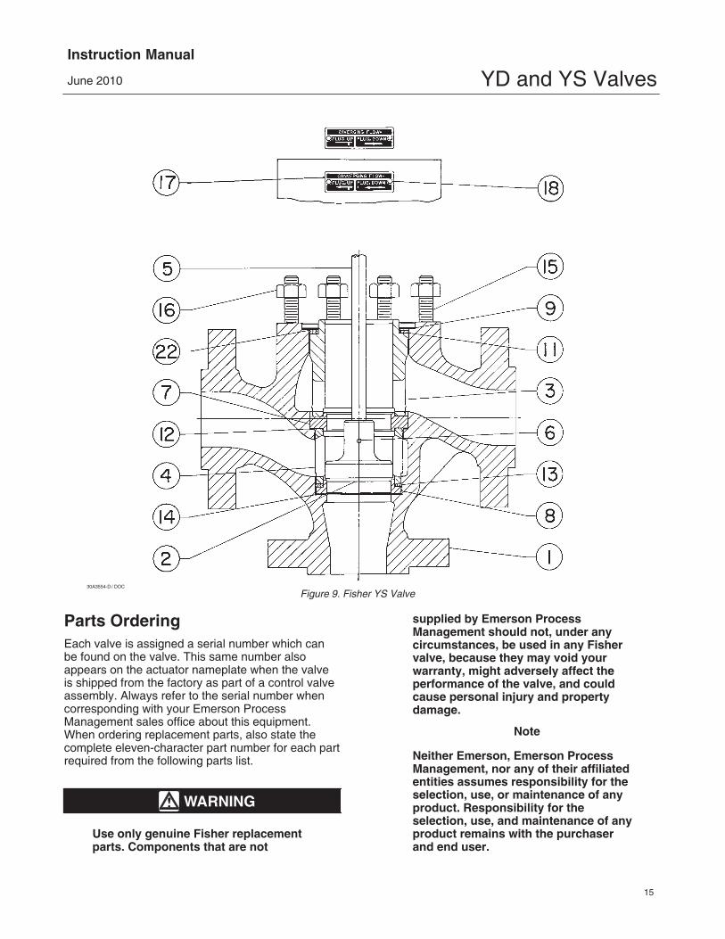
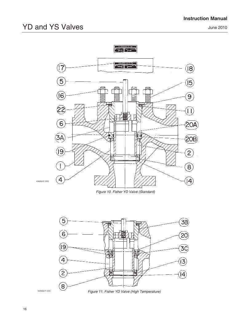
The common port for the YD is thebottom port as shown on the flowdirection plates (key 17) in figure 10.The common port for the YS is theleft-hand port as shown on the flowdirection plates in figure 9.
7. YD or YS control valves can be installed in anyposition, although the recommended position is withthe actuator vertical above the valve. For NPS 4 and 6YS valves, size 80 or larger actuators mountedbetween 45 degrees above and 45 degrees belowhorizontal should be supported. If forces other thannormal gravitational forces are experienced, such asvibrational forces, smaller size actuators might alsoneed to be supported when they are not in a verticalposition. For further information, consult your EmersonProcess Management sales office.
Table 2. Valve Body Sizes and End ConnectionsVALVES
SIZE, NPSCAST IRON VALVES STEEL OR STAINLESS
STEEL VALVES
1/2, 3/4 - - - NPT screwed orsocket weld
1 - - - NPT screwed; CL150,300, or 600 raised-faceor ring-type joint flanged;buttwelding; or socket weld
1-1/2, 2 NPT screwed; CL125flat-face flanged; orCL250 raised-faceflanged
NPT screwed; CL150,300, or 600 raised-faceor ring-type joint flanged;buttwelding; or socket weld
2-1/2, 3, 4, 6 CL125 flat-face orCL250 raised-faceflanged
CL150, 300, or 600raised face or ring-typejoint flanged; or buttwelding
WARNING
Personal injury could result frompacking leakage. Valve packing wastightened before shipment; however,the packing might require somereadjustment to meet specific serviceconditions. Check with your processor safety engineer for any additionalmeasures that must be taken toprotect against process media.
Valves with ENVIRO-SEAL live-loaded packing orHIGH-SEAL live-loaded packing will not require thisinitial re-adjustment. See the Fisher instructionmanuals titled ENVIRO-SEAL Packing System forSliding-Stem Valves or HIGH-SEAL Live-LoadedPacking System (as appropriate) for packinginstructions. If you wish to convert your presentpacking arrangement to ENVIRO-SEAL packing,refer to the retrofit kits listed in the parts kitsubsection near the end of this manual.
MaintenanceValve parts are subject to normal wear and must beinspected and replaced as necessary. Inspectionand maintenance frequency depends on the severityof service conditions. This section includesinstructions for trim maintenance, packingmaintenance, and ENVIRO-SEAL bellows sealbonnet replacement. All maintenance operationsmay be performed with the valve in the line.
WARNING
Avoid personal injury or propertydamage from sudden release of

YD and YS ValvesInstruction Manual
June 2010
4
process pressure or uncontrolledmovement of parts. Before performingany maintenance operations:
� Do not remove the actuator fromthe valve while the valve is stillpressurized.
� Always wear protective gloves,clothing, and eyewear whenperforming any maintenanceoperations to avoid personal injury.
� Disconnect any operating linesproviding air pressure, electric power,or a control signal to the actuator. Besure the actuator cannot suddenly openor close the valve.
� Use bypass valves or completelyshut off the process to isolate thevalve from process pressure. Relieveprocess pressure from both sides ofthe valve. Drain the process mediafrom both sides of the valve.
� Vent the power actuator loadingpressure and relieve any actuatorspring precompression.
� Use lock-out procedures to besure that the above measures stay ineffect while you work on theequipment.
� The valve packing box maycontain process fluids that arepressurized, even when the valve hasbeen removed from the pipeline.Process fluids may spray out underpressure when removing the packinghardware or packing rings, or whenloosening the packing box pipe plug.
� Check with your process or safetyengineer for any additional measuresthat must be taken to protect againstprocess media.
CAUTION
Follow instructions carefully to avoiddamaging the product surfaces, whichcould result in damage to the product.
Figure 2. Lubricator and Lubricator/Isolating Valve (Option-al)
LUBRICATOR
LUBRICATOR/ISOLATING VALVE10A9421-AAJ5428-DA0832-2/IL
Packing Lubrication
Note
ENVIRO-SEAL and HIGH-SEALpacking do not require lubrication.
WARNING
To avoid personal injury or propertydamage resulting from fire orexplosion, do not lubricate packingused in oxygen service or inprocesses with temperatures over260�C (500�F).
If a lubricator or lubricator/isolating valve (figure 2) isprovided for PTFE/composition or other packingsthat require lubrication, it will be installed in place ofthe pipe plug (key 14, figure 12). Use a good qualitysilicon-base lubricant. Do not lubricate packing usedin oxygen service or in processes with temperaturesover 260�C (500�F). To operate the lubricator,simply turn the cap screw clockwise to force thelubricant into the packing box. Thelubricator/isolating valve operates the same wayexcept open the isolating valve before turning thecap screw and then close the isolating valve afterlubrication is completed.

YD and YS ValvesInstruction Manual
June 2010
5
Table 3. Recommended Torque for Packing Flange Nuts
VALVE STEMDIAMETER PRESSURE
RATING
GRAPHITE TYPE PACKING PTFE TYPE PACKING
Minimum Torque Maximum Torque Minimum Torque Maximum Torque
mm Inches N�m Lbf�in N�m Lbf�in N�m Lbf�in N�m Lbf�in
9.5 3/8
CL125,150
3 27 5 40 1 13 2 19
CL250,300
4 36 6 53 2 17 3 26
CL600 6 49 8 73 3 23 4 35
12.7 1/2
CL125,150
5 44 8 66 2 21 4 31
CL250,300
7 59 10 88 3 28 5 42
CL600 9 81 14 122 4 39 7 58
19.1 3/4
CL125,150
11 99 17 149 5 47 8 70
CL250,300
15 133 23 199 7 64 11 95
CL600 21 182 31 274 10 87 15 131
25.4 1CL300 26 226 38 339 12 108 18 162
CL600 35 310 53 466 17 149 25 223
Packing Maintenance
Note
For valves with ENVIRO-SEALpacking, see the Fisher instructionmanual ENVIRO-SEAL Packing Systemfor Sliding-Stem Valves for packinginstructions.
For valves with HIGH-SEAL packing,see the Fisher instruction manualHIGH-SEAL Live-Loaded PackingSystem for packing instructions.
Packing Replacement
WARNING
Observe the warning at the start of theMaintenance section.
The following procedure covers PTFE V-ring packing.A similar procedure can be followed forPTFE/composition packing. However, becausePTFE/composition packing comes in split rings, it ispossible to replace the rings without removing theactuator from the valve.
Installation of graphite ribbon/filament packingrequires special care to avoid trapping air between
the rings. Start only one ring at a time without forcingthe top of the packing ring below the bottom of theentrance chamfer of the packing box. Thus, when aring is added, the stack should not be pushed intothe cavity more than the thickness of the added ring.
The arrangement of packing box parts is shown infigures 3, 4, 5, 6, and 7. Key numbers used in thefollowing steps are shown in figures 12 and 13.
1. Remove the actuator and bonnet according tosteps 1 through 4 of the Disassembly procedure inthe Maintenance section on page 8.
2. With the stem and valve plug assembly removedfrom the bonnet, remove the packing nuts (key 5),packing flange (key 3), wiper ring (key 12), andpacking follower (key 13) from the bonnet. The oldpacking can then be pulled out with a packing hook(take care to avoid scratching the packing box wall) orpushed out using a rod inserted through the bottom ofthe bonnet.
3. Clean the packing box and all metal parts.
4. Complete maintenance necessary on other partsand install the bonnet on the valve as indicated inthe Assembly section (starting on page 10).
5. Install the new packing and associated parts inthe sequence shown in figures 3, 4, 5, 6, and 7. Becareful not to damage the packing during installation.
6. Replace the packing flange and packing flangenuts.

YD and YS ValvesInstruction Manual
June 2010
6
Figure 3. Fisher PTFE V-Ring Packing Arrangements
UPPER WIPER(KEY 12)
PACKING FOLLOWER (KEY 13
LANTERN RING(KEY 8)
PACKING BOXRING (KEY 11)
MALE ADAPTOR
PACKING RING
FEMALE ADAPTOR
LOWER WIPERASSEMBLY 1(POSITIVE
PRESSURES)
ASSEMBLY 2(VACUUM)
ASSEMBLY 3(POSITIVE
PRESSURES& VACUUM)
ASSEMBLY 1(POSITIVE
PRESSURES)
ASSEMBLY 2(VACUUM)
ASSEMBLY 3(POSITIVE
PRESSURES& VACUUM)
ASSEMBLY 1(POSITIVE
PRESSURES)
ASSEMBLY 2(VACUUM)
ASSEMBLY 3(POSITIVE
PRESSURES& VACUUM)
9.5 mm (3/8 INCH) STEM 12.7 mm (1/2 INCH) STEM 19.1, 25.4, OR 31.8 mm(3/4, 1, OR 1‐1/4 INCH) STEM
DOUBLE ARRANGEMENTS
12A8187-C 12A7814-C 12A7839-A
B1428-2
UPPER WIPER(KEY 12)
PACKING FOLLOWER (KEY 13)
PACKING BOXRING (KEY 11)
FOR 316 OR 17‐4PH SSTMETAL PACKING BOX PARTS
SINGLE ARRANGEMENT12A7837-AB1429-2 / IL
FOR ALL OTHER METAL PACKINGBOX PART MATERIALS
SPACER (KEY 8)
UPPER WIPER(KEY 12)
PACKING FOLLOWER(KEY 13)
PACKING BOXRING (KEY 11)
FEMALEADAPTOR
FEMALEADAPTOR
MALEADAPTOR
PACKINGRING
MALEADAPTOR
PACKINGRING
WASHER(KEY 10)
SPRING(KEY 8)
PACKINGSET(KEY 6)
LOWERWIPER
LOWERWIPER
For spring-loaded PTFE V-ring packing, tightenthe packing flange nuts until the shoulder on thepacking follower contacts the bonnet.
For graphite packing, tighten the packing flangenuts to the maximum recommended torque shown intable 3. Then, loosen the packing flange nuts, andretighten them to the recommended minimum torqueshown in table 3.
For other packing types, tighten the packing flangenuts alternately in small equal increments until one
of the nuts reaches the minimum recommendedtorque shown in table 3. Then, tighten the remainingflange nut until the packing flange is level and at a90-degree angle to the valve stem.
For ENVIRO-SEAL or HIGH-SEAL live-loadedpacking, refer to the note at the beginning of thePacking Maintenance section.
7. Mount the actuator on the bonnet and make upthe stem connection according to the proceduregiven in the appropriate actuator instruction manual.
YD and YS ValvesInstruction Manual
June 2010
7
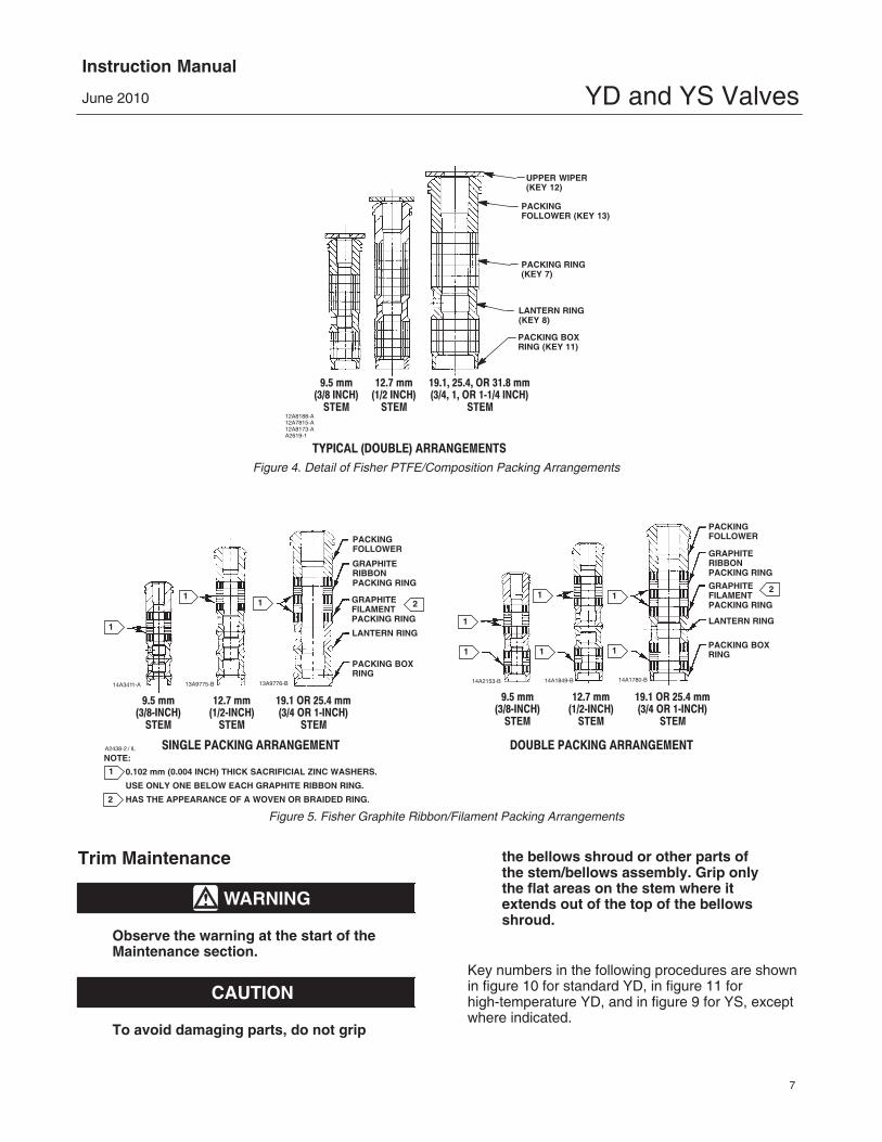
Figure 4. Detail of Fisher PTFE/Composition Packing Arrangements
UPPER WIPER(KEY 12)
PACKING FOLLOWER (KEY 13)
LANTERN RING(KEY 8)
PACKING BOXRING (KEY 11)
PACKING RING(KEY 7)
9.5 mm(3/8 INCH)
STEM
12.7 mm(1/2 INCH)
STEM
19.1, 25.4, OR 31.8 mm(3/4, 1, OR 1‐1/4 INCH)
STEM
TYPICAL (DOUBLE) ARRANGEMENTS
12A8188-A12A7815-A12A8173-AA2619-1
Figure 5. Fisher Graphite Ribbon/Filament Packing Arrangements
PACKINGFOLLOWER
PACKING BOXRING
1
GRAPHITERIBBONPACKING RING
GRAPHITEFILAMENTPACKING RING
14A1780-B14A1849-B14A2153-B
12.7 mm(1/2‐INCH)
STEM
9.5 mm(3/8‐INCH)
STEM
19.1 OR 25.4 mm(3/4 OR 1‐INCH)
STEM
1
1
11
1
NOTE:
0.102 mm (0.004 INCH) THICK SACRIFICIAL ZINC WASHERS.
USE ONLY ONE BELOW EACH GRAPHITE RIBBON RING.
HAS THE APPEARANCE OF A WOVEN OR BRAIDED RING.
A2438-2 / IL
1
2
LANTERN RING
2
PACKINGFOLLOWER
PACKING BOXRING
GRAPHITERIBBONPACKING RING
GRAPHITEFILAMENTPACKING RING
211
1
13A9776-B13A9775-B14A3411-A
12.7 mm(1/2‐INCH)
STEM
9.5 mm(3/8‐INCH)
STEM
19.1 OR 25.4 mm(3/4 OR 1‐INCH)
STEM
SINGLE PACKING ARRANGEMENT DOUBLE PACKING ARRANGEMENT
LANTERN RING
Trim Maintenance
WARNING
Observe the warning at the start of theMaintenance section.
CAUTION
To avoid damaging parts, do not grip
the bellows shroud or other parts ofthe stem/bellows assembly. Grip onlythe flat areas on the stem where itextends out of the top of the bellowsshroud.
Key numbers in the following procedures are shownin figure 10 for standard YD, in figure 11 forhigh-temperature YD, and in figure 9 for YS, exceptwhere indicated.

YD and YS ValvesInstruction Manual
June 2010
8
Figure 6. PTFE Packing Arrangements for Use in Fisher ENVIRO-SEAL Bellows Seal Bonnets
UPPER WIPER(KEY 12)
PACKING SET: (KEY 6) FEMALE ADAPTOR
PACKING RING MALE ADAPTOR
BUSHING (KEY 13)
9.5 mm(3/8 INCH)
STEM
12.7 mm(1/2 INCH)
STEM
DOUBLE ARRANGEMENTS
9.5 mm(3/8 INCH)
STEM
9.5 mm(3/8 INCH)
STEM
12.7 mm(1/2 INCH)STEM FOR
NPS 2 VALVES
12.7 mm(1/2 INCH)STEM FOR
NPS 3 AND 4 VALVES
THRUSTRING
(KEY 39)
SPRING(KEY 8)THRUST
RING(KEY 39)
THRUSTRING
(KEY 39)
BUSHING(KEY 13)
BUSHING(KEY 13)
SPACER(KEY 8)
SPACER(KEY 8)
SPACER(KEY 8)
12.7 mm(1/2 INCH)
STEM
SINGLE ARRANGEMENTS
FOR S31600 (316 SST)PACKING BOX PARTS
FOR ALL PACKING BOXMATERIALS EXCEPT S31600
UPPER WIPER(KEY 12)
PACKING SET: (KEY 6) FEMALE ADAPTOR PACKING RING MALE ADAPTOR
BUSHING (KEY 13)
SPACER(KEY 8)
A5863
12B4183-A 18A0906-D 18A5338-A
12B4182-A SHT1
12B4185-A SHT 1 12B4182-A SHT 2 12B4185-A SHT 2
Disassembly1. Isolate the control valve from the line pressure,release pressure from both sides of the valve, anddrain the process media from both sides of thevalve. Remove actuator supply pressure, and uselock-out procedures to be sure that the abovemeasures stay in effect while you work on theequipment.
WARNING
See the WARNING at the beginning ofthe Maintenance section for moreinformation.
2. Disconnect the actuator stem connector andremove the locknut (key 15, figure 12) that holds theactuator to the valve. (Valves with a 127 mm (5-inch)yoke boss use cap screws and nuts to secure theactuator on the valve). Then lift the actuator from thevalve.
3. Remove the nuts (key 16, figures 9 and 10) orcap screws from the bonnet flange.
4. Lift off the bonnet along with the valve plug andstem (keys 2 and 5, figures 9 and 10). Due to thedesign of the valve, several other trim parts will bedrawn out with the valve plug. They are as follows:

YD and YS ValvesInstruction Manual
June 2010
9
Figure 7. Double Graphite Ribbon/Filament Arrangements for Use in Fisher ENVIRO-SEAL Bellows Seal Bonnets
BUSHING(KEY 13)
SPACER(KEY 8)
1
GRAPHITEFILAMENTPACKING RING(KEY 7)
GRAPHITERIBBONPACKING RING(KEY 7)
12B6102-A18A0909-D12B4181-A
12.7 mm(1/2‐INCH)STEM FOR
NPS 2 VALVES
9.5 mm(3/8‐INCH)
STEM
12.7 mm(1/2‐INCH)STEM FOR
NPS 3 AND 4 VALVES
1
1
1
1
1
NOTE:
0.102 mm (0.004 INCH) THICK SACRIFICIAL ZINC WASHERS;
USE ONLY ONE BELOW EACH GRAPHITE RIBBON RING.A5870
1
YD (Standard)--The upper cage (key 3A) andassociated seals, gaskets, and shim (keys 9, 11, 19,20A, 20B, and 22).
YD (High Temperature)--The upper cage (key 3B)and associated gaskets and shim (keys 9, 11, and 22).
YS--The upper seat (key 7), upper cage (key 3), andassociated gaskets and shim (keys 9, 11, and 22).
CAUTION
The exposed portion of the cageprovides a guiding surface that mustnot be damaged during disassembly ormaintenance. Damage could affectvalve performance. If the cage is stuckin the valve, use a rubber mallet tostrike the exposed portion at severalpoints around the circumference.
Take proper care not to damage any sealing orseating surfaces as nicks or scratches in these partsmight cause leakage.
5. Loosen the packing flange nuts (key 5, figures 12and 13) and draw the valve plug and stem straightout the bottom of the bonnet. Lift all cage and seatparts off the valve plug and stem. If the stem for YDor YS requires replacing, drive the pin (key 6) outand unscrew the stem from the plug.
Table 4. Pin Drill Sizes
VALVE TYPEVALVE STEM
CONNECTION, mm(INCH)
DRILL SIZE, INCHES
YD & YS
9.5 (3/8)12.7 (1/2)
3/321/8
19.1 (3/4)25.4 (1)
3/161/4
Table 5. Recommended Bolt Torquesfor Body-to-Bonnet Bolting(1)
VALVE SIZE,NPS
RECOMMENDED BOLTTORQUE, N�m (Lbf�ft)
1/2, 3/41, 1-1/2
129 (95)129 (95)
22-1/2
96 (71)96 (71)
346
169 (125)271 (200)549 (405)
1. For other materials, contact your Emerson Process Management sales office.
6. To replace the adaptor (key 24, figure 14) onENVIRO-SEAL bellows seal bonnets, place theplug stem assembly and valve plug in a soft-jawchuck or other type of vise so that the jaws grip aportion of the valve plug that is not a seating surface.Drive out the pin (key 36, figure 14). Reverse theplug stem assembly in the soft-jaw chuck or vise.Grip the flat areas on the valve stem just below thethreads for the actuator/stem connection. Unscrewthe valve plug/adaptor assembly (key 24, figure 14)from the valve stem assembly (key 20, figure 14).
CAUTION
Never use an old stem with a newvalve plug. The use of an old stemrequires drilling a new pin holethrough the stem (or adaptor, in casean ENVIRO-SEAL bellows seal bonnetis being used). This drilling weakensthe stem or adaptor and may causefailure in service. However, a usedvalve plug may be reused with a newstem or adaptor.
7. The internal parts of the bonnet can now bedisassembled, if necessary. For packingreplacement, refer to the section entitled PackingReplacement on page 5.
8. Standard YD Only—It is recommended that thecage seal (key 19), seal ring (key 20A), and backupring (key 20B) be replaced upon assembly. Thesecan be removed by prying them out of the uppercage grooves with a screwdriver or a soft-tippedinstrument. If a screwdriver is used, take care not toscratch the surfaces of the cage.
YD and YS ValvesInstruction Manual
June 2010
10
9. The remaining trim parts can now be lifted out ofthe valve. Under severe service conditions, some ofthese parts might have become stuck to the valve. Inthis case, it might be necessary to use a seat ringpuller to remove these parts. Because there is aslight clearance around the outer circumference ofthe lower cage (key 4) and seat ring (key 8), it mightbe possible to remove these by tapping them loose,if interior room permits.
AssemblyYD (Standard)
1. Use new gaskets, seals, and shim (keys 9, 11, 14, 19, 20A, 20B, and 22) on assemblyand wipe all sealing surfaces with a clean cloth.
2. Install the seat ring gasket (key 14) and place theseat ring (key 8) on top of the gasket.
3. Install the lower cage (key 4) into the valve, beingcertain that it fits down over the raised portion of theseat ring. The narrow portion of the cage windowsshould point downward.
4. Slip the O-ring cage seal (key 19) over thebottom of the upper cage (key 3A) and into the cagegroove.
5. Press the backup ring (key 20B) and the seal ring(key 20A), respectively, into the inner groove of theupper cage. It might be necessary to bend one sideof each of these in slightly to accomplish this. Takecare not to distort the rings when doing this.
6. If a new stem (key 5) is to be used, screw thestem into the valve plug (key 2) until it wedges tightat the end of the valve stem thread.
CAUTION
Never use an old stem with a newvalve plug. The use of an old stemrequires drilling a new pin holethrough the stem (or adaptor, in casean ENVIRO-SEAL bellows seal bonnetis being used). This drilling weakensthe stem or adaptor and may causefailure in service. However, a usedvalve plug may be reused with a newstem or adaptor.
Locate the pilot hole in the valve plug and drill thehole through the plug and stem assembly (determinedrill size from table 4). Drive in the pin to lock theassembly.
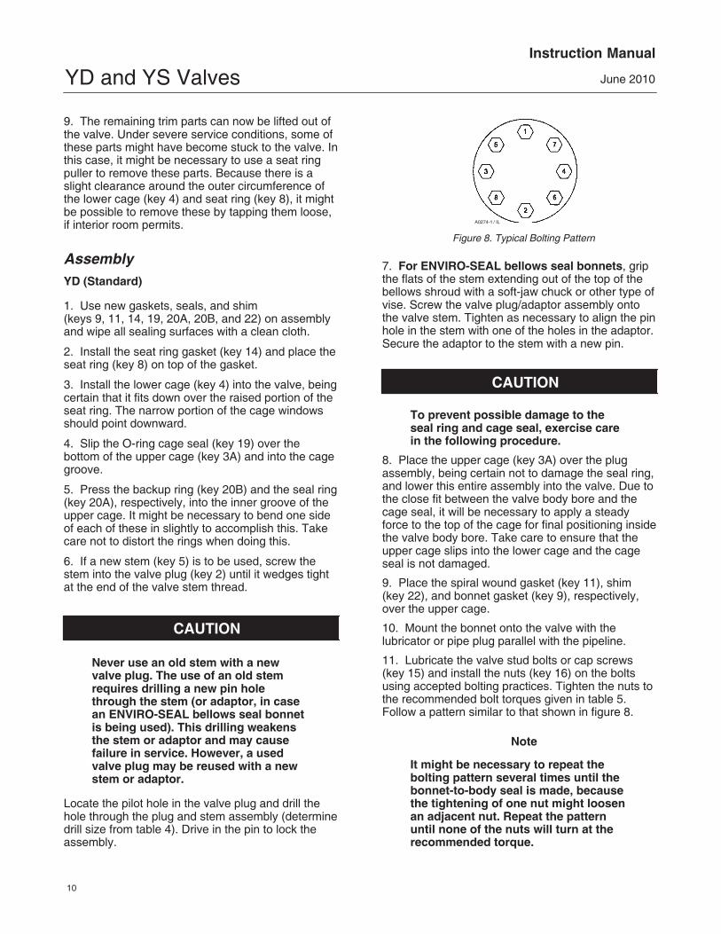
Figure 8. Typical Bolting Pattern
A0274-1 / IL
7. For ENVIRO-SEAL bellows seal bonnets, gripthe flats of the stem extending out of the top of thebellows shroud with a soft-jaw chuck or other type ofvise. Screw the valve plug/adaptor assembly ontothe valve stem. Tighten as necessary to align the pinhole in the stem with one of the holes in the adaptor.Secure the adaptor to the stem with a new pin.
CAUTION
To prevent possible damage to theseal ring and cage seal, exercise carein the following procedure.
8. Place the upper cage (key 3A) over the plugassembly, being certain not to damage the seal ring,and lower this entire assembly into the valve. Due tothe close fit between the valve body bore and thecage seal, it will be necessary to apply a steadyforce to the top of the cage for final positioning insidethe valve body bore. Take care to ensure that theupper cage slips into the lower cage and the cageseal is not damaged.
9. Place the spiral wound gasket (key 11), shim (key 22), and bonnet gasket (key 9), respectively,over the upper cage.
10. Mount the bonnet onto the valve with thelubricator or pipe plug parallel with the pipeline.
11. Lubricate the valve stud bolts or cap screws(key 15) and install the nuts (key 16) on the boltsusing accepted bolting practices. Tighten the nuts tothe recommended bolt torques given in table 5.Follow a pattern similar to that shown in figure 8.
Note
It might be necessary to repeat thebolting pattern several times until thebonnet-to-body seal is made, becausethe tightening of one nut might loosenan adjacent nut. Repeat the patternuntil none of the nuts will turn at therecommended torque.

YD and YS ValvesInstruction Manual
June 2010
11
12. Mount the actuator on the bonnet and make upthe stem connection according to the proceduregiven in the appropriate actuator instruction manual.
YD (High Temperature)
1. Use new gaskets, seals, and shim (keys 9, 11, 13, 14, 19, 20, and 22) on assembly andwipe all sealing surfaces with a clean cloth.
2. Install the seat ring gasket (key 14) and place theseat ring (key 8) on top of the gasket followed by thespiral wound spring (key 13).
3. Install the lower cage (key 4) into the valve, beingcertain that it fits down over the raised portion of theseat ring. The narrow portion of the cage windowsshould point downward.
4. Place one of the retaining ring gaskets (key 19)into the valve.
5. If a new stem (key 5) is to be used, screw thestem into the valve plug (key 2) until it wedges tightat the end of the valve stem thread.
CAUTION
Never use an old stem with a newvalve plug. The use of an old stemrequires drilling a new pin holethrough the stem (or adaptor, in casean ENVIRO-SEAL bellows seal bonnetis being used). This drilling weakensthe stem or adaptor and may causefailure in service. However, a usedvalve plug may be reused with a newstem or adaptor.
Locate the pilot hole in the valve plug and drill thehole through the plug and stem assembly (determinedrill size from table 4). Drive in the pin to lock theassembly.
6. For ENVIRO-SEAL bellows seal bonnets, gripthe flats of the stem extending out of the top of thebellows shroud with a soft-jaw chuck or other type ofvise. Screw the valve plug/adaptor assembly ontothe valve stem. Tighten as necessary to align the pinhole in the stem with one of the holes in the adaptor.Secure the adaptor to the stem with a new pin.
7. Place the seal ring retainer (key 3C) into thevalve and lower the valve plug assembly into theretainer orifice.
8. Carefully place the seal rings (key 20) over thevalve plug, being certain that they rest against the
retaining ring. Each of these has a cut through itscross section. These cuts should be oriented 180degrees apart to ensure a proper seal.
9. Insert the other retaining ring gasket (key 19) ontop of the retaining ring.
10. Lower the upper cage (key 3B) into the valve.When properly installed, the raised ring on thebottom of the cage should fit snugly into the grooveformed by the seal rings and the retaining ring.
11. Place the spiral wound gasket (key 11), shim(key 22), and bonnet gasket (key 9), respectively,over the upper cage.
12. Mount the bonnet onto the valve with thelubricator or pipe plug parallel with the pipeline.
13. Lubricate the valve stud bolts (key 15) andinstall the nuts (key 16) onto the bolts using goodbolting practices. Tighten the nuts to therecommended bolt torques given in table 5. Apattern similar to that shown in figure 8 should befollowed.
Note
It might be necessary to repeat thebolting pattern several times until thebonnet-to-body seal is made, becausethe tightening of one nut might loosenan adjacent nut. Repeat the patternuntil none of the nuts will turn at therecommended torque.
14. Mount the actuator on the bonnet and make upthe stem connection according to the proceduregiven in the appropriate actuator instruction manual.
YS
1. Use new gaskets and shim (keys 9, 11, 12, 13,14 and 22) on assembly and wipe all sealingsurfaces with a clean cloth.
2. Install the lower seat ring gasket (key 14) andplace the lower seat ring (key 8) on top of the gasketfollowed by the spiral wound spring (key 13).
3. Install the lower cage (key 4) into the valve, beingcertain that it fits down over the raised portion of theseat ring. The narrow portion of the cage windowsshould point downward.
4. Place the upper seat ring gasket (key 12) into thevalve.
5. If a new stem (key 5) is to be used, screw thestem into the valve plug (key 2) until it wedges tightat the end of the valve stem thread.

YD and YS ValvesInstruction Manual
June 2010
12
CAUTION
Never use an old stem with a newvalve plug. The use of an old stemrequires drilling a new pin holethrough the stem (or adaptor, in casean ENVIRO-SEAL bellows seal bonnetis being used). This drilling weakensthe stem or adaptor and may causefailure in service. However, a usedvalve plug may be reused with a newstem or adaptor.
Locate the pilot hole in the valve plug and drill thehole through the plug and stem assembly (determinedrill size from table 4). Drive in the pin to lock theassembly.
6. For ENVIRO-SEAL bellows seal bonnets, gripthe flats of the stem extending out of the top of thebellows shroud with a soft-jaw chuck or other type ofvise. Screw the valve plug/adaptor assembly ontothe valve stem. Tighten as necessary to align the pinhole in the stem with one of the holes in the adaptor.Secure the adaptor to the stem with a new pin.
7. Place the upper seat ring (key 7) and upper cage(key 3), respectively, over the plug and stemassembly, being certain not to scratch any sealingsurfaces. Lower this entire assembly into the valve.
8. Place the spiral wound gasket (key 11), shim (key 22), and bonnet gasket (key 9), respectively,over the upper cage.
9. Mount the bonnet onto the valve with thelubricator or pipe plug parallel with the pipeline.
10. Lubricate the valve stud bolts or cap screws(key 15) and install the nuts (key 16) onto the boltsusing good bolting practices. Tighten the nuts to therecommended bolt torques given in table 5. Apattern similar to that shown in figure 8 should befollowed.
Note
It might be necessary to repeat thebolting pattern several times until thebonnet-to-body seal is made, becausethe tightening of one nut might loosenan adjacent nut. Repeat the patternuntil none of the nuts will turn at therecommended torque.
11. Mount the actuator onto the bonnet and makeup the stem connection according to the proceduregiven in the appropriate actuator instruction manual.
ENVIRO-SEAL Bellows Seal Bonnet
Replacing a Plain or Extension Bonnetwith an ENVIRO-SEAL Bellows SealBonnet (Stem/Bellows Assembly)1. Remove the actuator and bonnet according tosteps 1 through 4 of the Disassembly procedure inthe Maintenance section on page 8.
2. With care, remove the valve plug and stemassembly from the valve. If necessary, also lift outthe cage.
CAUTION
To prevent possible product damage,cover the opening in the valve in thefollowing procedure to protect thesealing surfaces and to preventforeign material from getting into thevalve body cavity.
3. Remove and discard the existing bonnet gasket.Cover the valve body opening to protect sealingsurfaces and to prevent foreign material fromentering the valve body cavity.
Note
The ENVIRO-SEAL stem/bellowsassembly for YD and YS valves isavailable only with a threaded anddrilled plug/adaptor/stem connection.The existing valve plug can be reusedwith the new stem/bellows assemblyor a new plug can be installed.
4. Inspect the existing valve plug. If the plug is ingood condition, it can be reused with the newENVIRO-SEAL stem/bellows assembly. To removethe existing valve plug from the stem, first, place theexisting plug stem assembly and valve plug in asoft-jaw chuck or other type of vise so that the jawsgrip a portion of the valve plug that is not a seatingsurface. Drive out or drill out the pin (key 8).
5. Reverse the plug stem assembly in the soft-jawchuck or vise. Grip the valve stem in an appropriateplace and unscrew the existing plug from the valvestem.
YD and YS ValvesInstruction Manual
June 2010
13
CAUTION
When installing a valve plug on theENVIRO-SEAL stem/bellows assembly,the valve stem must not be rotated.Damage to the bellows may result.
Do not grip the bellows shroud orother parts of the stem/bellowsassembly. Grip only the flat areas onthe stem where it extends out of thetop of the bellows shroud.
Note
The ENVIRO-SEAL stem/bellowsassembly has a one-piece stem.
6. To attach the valve plug to the stem of the newENVIRO-SEAL stem/bellows assembly, first attachthe plug to the adaptor (key 24). Locate the adaptor.Notice that a hole has not been drilled in the threadswhere the plug screws onto the adaptor. Secure thevalve plug in a soft-jaw chuck or other type of vise.Do not grip the plug on any seating surface. Positionthe plug in the chuck or vise for easy threading ofthe adaptor. Thread the adaptor into the valve plugand tighten to the appropriate torque value.
7. Select the proper size of drill bit and drill throughthe adaptor using the hole in the valve plug as aguide. Remove any metal chips or burrs and drive ina new pin to lock the plug/adaptor assemblytogether.
8. Attach the plug/adaptor assembly to theENVIRO-SEAL stem/bellows assembly by firstsecuring the stem/bellows assembly in a soft-jawchuck or other type of vise so that the jaws of thechuck or vise grip the flats of the stem extending outof the top of the bellows shroud. Screw the valveplug/adaptor assembly onto the valve stem. Tightenas necessary to align the pin hole in the stem withone of the holes in the adaptor. Secure the adaptorto the stem with a new pin.
9. Inspect the seat ring (key 9) and soft seat parts(keys 21, 22, and 23); replace, if necessary.
10. Place a new gasket (key 10) into the valve inplace of the bonnet gasket. Install the newstem/bellows assembly with valve plug/adaptor byplacing it into the valve on top of the new bellowsgasket.
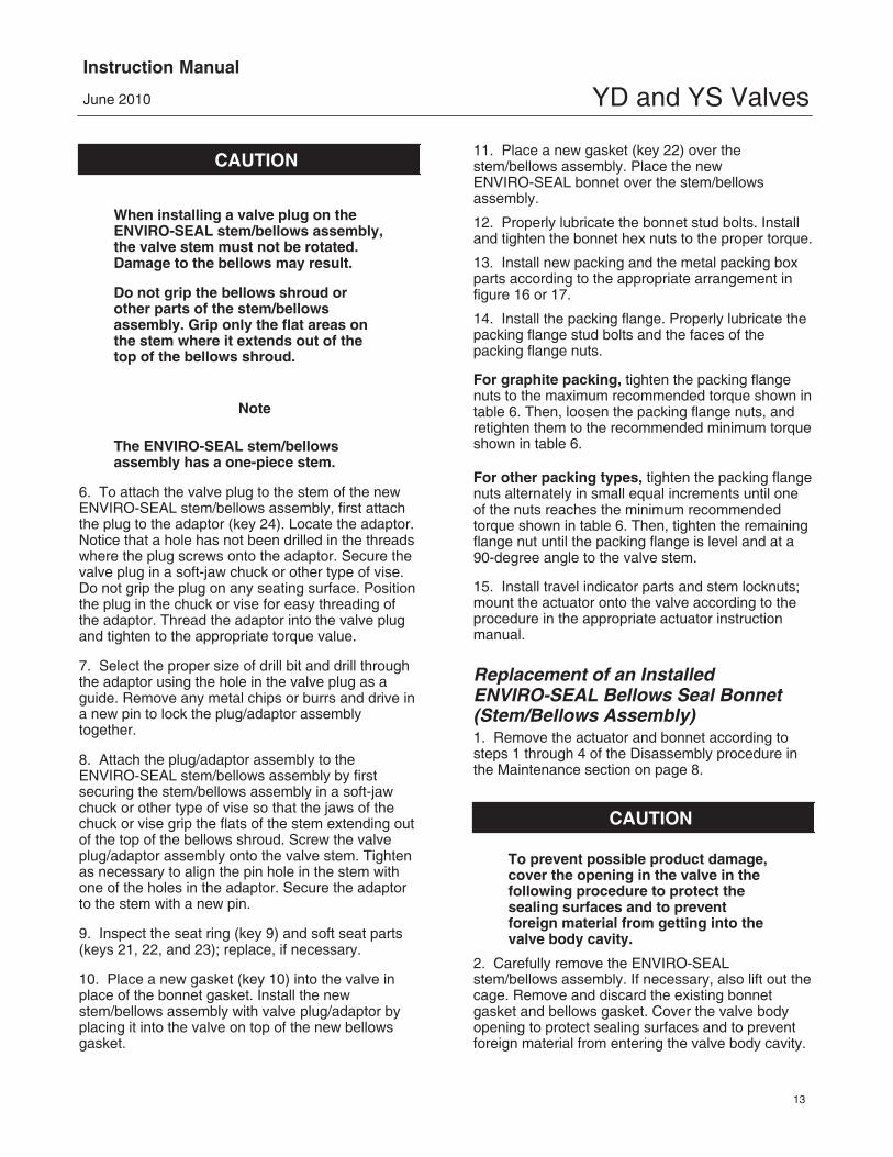
11. Place a new gasket (key 22) over thestem/bellows assembly. Place the newENVIRO-SEAL bonnet over the stem/bellowsassembly.
12. Properly lubricate the bonnet stud bolts. Installand tighten the bonnet hex nuts to the proper torque.
13. Install new packing and the metal packing boxparts according to the appropriate arrangement infigure 16 or 17.
14. Install the packing flange. Properly lubricate thepacking flange stud bolts and the faces of thepacking flange nuts.
For graphite packing, tighten the packing flangenuts to the maximum recommended torque shown intable 6. Then, loosen the packing flange nuts, andretighten them to the recommended minimum torqueshown in table 6.
For other packing types, tighten the packing flangenuts alternately in small equal increments until oneof the nuts reaches the minimum recommendedtorque shown in table 6. Then, tighten the remainingflange nut until the packing flange is level and at a90-degree angle to the valve stem.
15. Install travel indicator parts and stem locknuts;mount the actuator onto the valve according to theprocedure in the appropriate actuator instructionmanual.
Replacement of an InstalledENVIRO-SEAL Bellows Seal Bonnet(Stem/Bellows Assembly)1. Remove the actuator and bonnet according tosteps 1 through 4 of the Disassembly procedure inthe Maintenance section on page 8.
CAUTION
To prevent possible product damage,cover the opening in the valve in thefollowing procedure to protect thesealing surfaces and to preventforeign material from getting into thevalve body cavity.
2. Carefully remove the ENVIRO-SEALstem/bellows assembly. If necessary, also lift out thecage. Remove and discard the existing bonnetgasket and bellows gasket. Cover the valve bodyopening to protect sealing surfaces and to preventforeign material from entering the valve body cavity.
YD and YS ValvesInstruction Manual
June 2010
14
CAUTION
The ENVIRO-SEAL stem/bellowsassembly for YD and YS valves isavailable only with a threaded anddrilled plug/adaptor/stem connection.The existing valve plug can be reusedwith the new stem/bellows assemblyor a new plug can be installed. If theexisting valve plug is reused, and theadaptor is in good condition, it mayalso be reused. However, never reusean old adaptor with a new valve plug.Using an old adaptor with a new valveplug requires drilling a new pin hole inthe adaptor. This drilling weakens theadaptor and may cause failure inservice. However, a used valve plugmay be reused with a new adaptor.
3. Inspect the existing valve plug and adaptor. Ifthey are in good condition, they can be reused withthe new stem/bellows assembly and they do notneed to be separated.
CAUTION
When removing/installing a valve plugon the ENVIRO-SEAL stem/bellowsassembly, the valve stem must not berotated. Damage to the bellows mayresult.
Do not grip the bellows shroud orother parts of the stem/bellowsassembly. Grip only the flat areas onthe stem where it extends out of thetop of the bellows shroud.
Note
The ENVIRO-SEAL stem/bellowsassembly has a one-piece stem.
4. If the valve plug and adaptor are not in goodcondition and must be replaced, first remove thevalve plug/adaptor assembly from the stem/bellowsassembly; then remove the valve plug from theadaptor. First, place the stem/bellows assembly andvalve plug in a soft-jaw chuck or other type of vise sothat the jaws grip a portion of the valve plug that isnot a seating surface. Drive out or drill out the pin(key 6, figure 9, 10, or 11. Drive out the pin (key 36,figure 14).
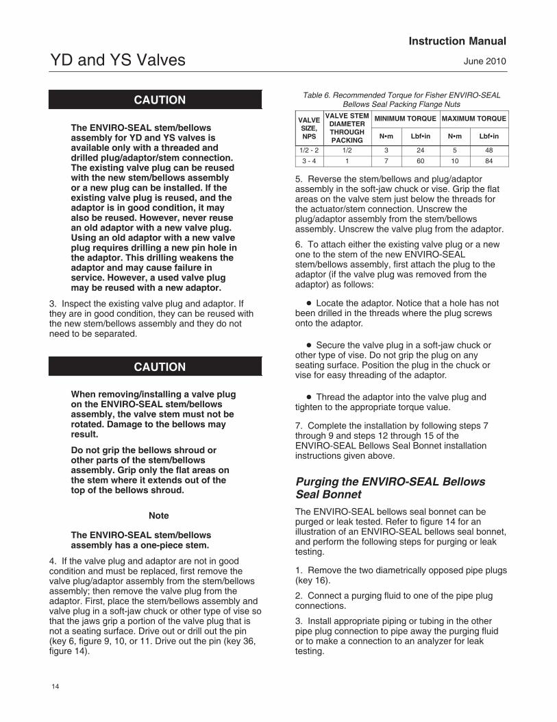
Table 6. Recommended Torque for Fisher ENVIRO-SEALBellows Seal Packing Flange Nuts
VALVESIZE,NPS
VALVE STEMDIAMETERTHROUGHPACKING
MINIMUM TORQUE MAXIMUM TORQUE
N�m Lbf�in N�m Lbf�in
1/2 - 2 1/2 3 24 5 48
3 - 4 1 7 60 10 84
5. Reverse the stem/bellows and plug/adaptorassembly in the soft-jaw chuck or vise. Grip the flatareas on the valve stem just below the threads forthe actuator/stem connection. Unscrew theplug/adaptor assembly from the stem/bellowsassembly. Unscrew the valve plug from the adaptor.
6. To attach either the existing valve plug or a newone to the stem of the new ENVIRO-SEALstem/bellows assembly, first attach the plug to theadaptor (if the valve plug was removed from theadaptor) as follows:
� Locate the adaptor. Notice that a hole has notbeen drilled in the threads where the plug screwsonto the adaptor.
� Secure the valve plug in a soft-jaw chuck orother type of vise. Do not grip the plug on anyseating surface. Position the plug in the chuck orvise for easy threading of the adaptor.
� Thread the adaptor into the valve plug andtighten to the appropriate torque value.
7. Complete the installation by following steps 7through 9 and steps 12 through 15 of theENVIRO-SEAL Bellows Seal Bonnet installationinstructions given above.
Purging the ENVIRO-SEAL BellowsSeal BonnetThe ENVIRO-SEAL bellows seal bonnet can bepurged or leak tested. Refer to figure 14 for anillustration of an ENVIRO-SEAL bellows seal bonnet,and perform the following steps for purging or leaktesting.
1. Remove the two diametrically opposed pipe plugs(key 16).
2. Connect a purging fluid to one of the pipe plugconnections.
3. Install appropriate piping or tubing in the otherpipe plug connection to pipe away the purging fluidor to make a connection to an analyzer for leaktesting.
YD and YS ValvesInstruction Manual
June 2010
15
Figure 9. Fisher YS Valve30A3554-D / DOC
Parts OrderingEach valve is assigned a serial number which canbe found on the valve. This same number alsoappears on the actuator nameplate when the valveis shipped from the factory as part of a control valveassembly. Always refer to the serial number whencorresponding with your Emerson ProcessManagement sales office about this equipment.When ordering replacement parts, also state thecomplete eleven-character part number for each partrequired from the following parts list.
WARNING
Use only genuine Fisher replacementparts. Components that are not
supplied by Emerson ProcessManagement should not, under anycircumstances, be used in any Fishervalve, because they may void yourwarranty, might adversely affect theperformance of the valve, and couldcause personal injury and propertydamage.
Note
Neither Emerson, Emerson ProcessManagement, nor any of their affiliatedentities assumes responsibility for theselection, use, or maintenance of anyproduct. Responsibility for theselection, use, and maintenance of anyproduct remains with the purchaserand end user.
YD and YS ValvesInstruction Manual
June 2010
16
Figure 10. Fisher YD Valve (Standard)
40A3552-F / DOC
Figure 11. Fisher YD Valve (High Temperature)40A3552-F / DOC

YD and YS ValvesInstruction Manual
June 2010
17
AU3910�A/ DOCE1087 PLAIN BONNET
Figure 12. Fisher Standard Bonnet
CU3911�C/ DOCSTYLE 1 OR 2
EXTENSION BONNET
Figure 13. Fisher Extension Bonnet Figure 14. Fisher ENVIRO-SEAL Bellows Seal Bonnet
� APPLY LUB
42B3947�A/ DOC
ENVIRO-SEALBELLOWS SEAL BONNET

YD and YS ValvesInstruction Manual
June 2010
18
Figure 15. Typical Fisher HIGH-SEAL Graphite ULF Packing System
39B4153-A
1. FIND NUMBER 219 NOT REQUIRED WITH 3/8 INCH STEM
Parts KitsPacking Kits (Non-Live-Loaded)
PACKING PARTS KITS
Stem Diameter, mm (Inches)Yoke Boss Diameter, mm (Inches)
9.5 (3/8)54 (2-1/8)
12.7 (1/2)71 (2-13/16)
19.1 (3/4)90 (3-9/16)
PTFEDouble PTFEPTFE/CompositionSingle Graphite Ribbon/Filament
Complete Packing Box RepairPacking Ring Only Repair
Double Graphite Ribbon/Filament
RPACKX00012RPACKX00042RPACKX00072
RPACKX00102RPACKX00132RPACKX00162
RPACKX00022RPACKX00052RPACKX00082
RPACKX00112RPACKX00142RPACKX00172
RPACKX00032RPACKX00062RPACKX00092
RPACKX00122RPACKX00152RPACKX00182
Packing Kits (ENVIRO-SEAL) Repair
PACKINGMATERIAL
STEM DIAMETER AND YOKE BOSS DIAMETER, mm (INCH)
9.5 (3/8)54 (2-1/8)
12.7 (1/2)71 (2-13/16)
19.1 (3/4)90 (3-9/16)
25.4 (1)127 (5)
Double PTFE (contains keys 214, 215, & 218) RPACKX00192 RPACKX00202 RPACKX00212 RPACKX00222
Graphite ULF (contains keys 207, 208, 209, 210, and 214) RPACKX00592 RPACKX00602 RPACKX00612 RPACKX00622
Packing Kits (ENVIRO-SEAL) Retrofit
PACKINGMATERIAL
STEM DIAMETER AND YOKE BOSS DIAMETER, mm (INCH)
9.5 (3/8)54 (2-1/8)
12.7 (1/2)71 (2-13/16)
19.1 (3/4)90 (3-9/16)
25.4 (1)127 (5)
Double PTFE (contains keys 200, 201, 211, 212, 214, 215, 217, and 218) RPACKXRT012 RPACKXRT022 RPACKXRT032 RPACKXRT042
Graphite ULF (contains keys 200, 201, 207, 208, 209, 210,211, 212, 214, and 217)
RPACKXRT262 RPACKXRT272 RPACKXRT282 RPACKXRT292
YD and YS ValvesInstruction Manual
June 2010
19
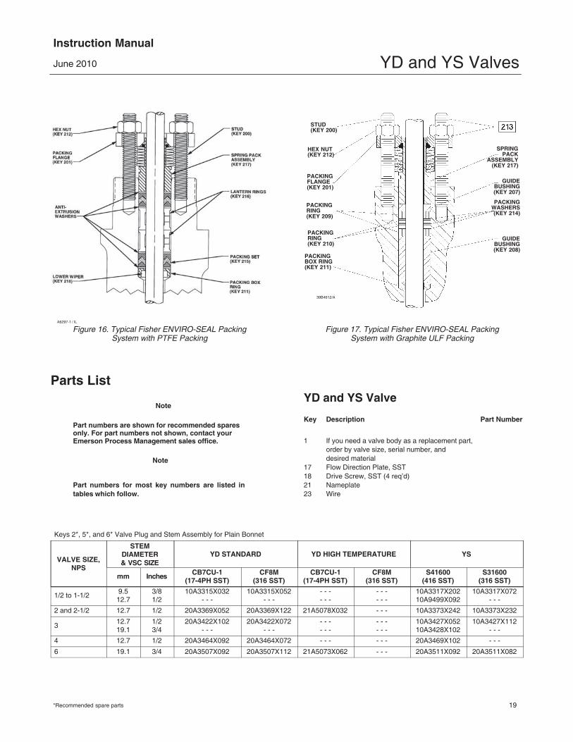
Figure 16. Typical Fisher ENVIRO-SEAL PackingSystem with PTFE Packing
A6297-1 / IL
Parts List
Note
Part numbers are shown for recommended sparesonly. For part numbers not shown, contact yourEmerson Process Management sales office.
Note
Part numbers for most key numbers are listed intables which follow.
Figure 17. Typical Fisher ENVIRO-SEAL PackingSystem with Graphite ULF Packing
PACKINGRING(KEY 209)
PACKINGRING(KEY 210)
PACKINGBOX RING(KEY 211)
STUD(KEY 200)
SPRINGPACK
ASSEMBLY(KEY 217)
HEX NUT(KEY 212)
PACKINGFLANGE(KEY 201)
GUIDEBUSHING(KEY 207)
PACKINGWASHERS(KEY 214)
GUIDEBUSHING(KEY 208)
39B4612/A
YD and YS Valve
Key Description Part Number
1 If you need a valve body as a replacement part,order by valve size, serial number, anddesired material
17 Flow Direction Plate, SST18 Drive Screw, SST (4 req’d)21 Nameplate23 Wire
Keys 2*, 5*, and 6* Valve Plug and Stem Assembly for Plain Bonnet
VALVE SIZE,NPS
STEMDIAMETER& VSC SIZE
YD STANDARD YD HIGH TEMPERATURE YS
mm Inches CB7CU-1(17-4PH SST)
CF8M(316 SST)
CB7CU-1(17-4PH SST)
CF8M(316 SST)
S41600(416 SST)
S31600(316 SST)
1/2 to 1-1/2 9.512.7
3/81/2
10A3315X032- - -
10A3315X052- - -
- - -- - -
- - -- - -
10A3317X20210A9499X092
10A3317X072- - -
2 and 2-1/2 12.7 1/2 20A3369X052 20A3369X122 21A5078X032 - - - 10A3373X242 10A3373X232
3 12.719.1
1/23/4
20A3422X102- - -
20A3422X072- - -
- - -- - -
- - -- - -
10A3427X05210A3428X102
10A3427X112- - -
4 12.7 1/2 20A3464X092 20A3464X072 - - - - - - 20A3469X102 - - -
6 19.1 3/4 20A3507X092 20A3507X112 21A5073X062 - - - 20A3511X092 20A3511X082
*Recommended spare parts
YD and YS ValvesInstruction Manual
June 2010
20
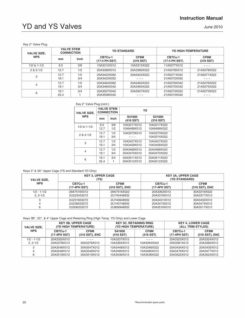
Key 2* Valve Plug
VALVE SIZE,NPS
VALVE STEMCONNECTION
YD STANDARD YD HIGH-TEMPERATURE
mm Inch CB7Cu-1(17-4 PH SST)
CF8M(316 SST)
CB7Cu-1(17-4 PH SST)
CF8M(316 SST)
1/2 to 1-1/2 9.5 3/8 10A3315X012 10A3315X022 11A5077X012 � � �
2 & 2-1/2 12.7 1/2 20A3369X012 20A3369X022 21A5078X012 21A5078X022
3 12.719.1
1/23/4
20A3422X09220A3423X052
20A3422X022� � �
21A5071X04221A5072X052
21A5071X022� � �
4 12.719.1
1/23/4
20A3464X08220A3465X042
20A3464X02220A3465X022
21A5076X04221A5075X042
21A5076X02221A5075X022
6 19.125.4
3/41
20A3507X04220A3508X042
20A3507X022� � �
21A5073X05221A5074X042
21A5073X022� � �
Key 2* Valve Plug (cont.)
VALVE SIZE,NPS
VALVE STEMCONNECTION
YS
mm Inch S41600(416 SST)
S31600(316 SST)
1/2 to 1-1/2 9.512.7
3/81/2
10A3317X01210A9499X012
10A3317X02210A9499X022
2 & 2-1/2 12.719.1
1/23/4
10A3373X012� � �
10A3373X02210A3374X022
3 12.719.1
1/23/4
10A3427X01210A3428X012
10A3427X02210A3428X022
4 12.719.1
1/23/4
20A3469X01220A3470X012
20A3469X02220A3470X022
6 19.125.4
3/41
20A3511X01220A3512X012
20A3511X02220A3512X022
Keys 3* & 3A* Upper Cage (YS and Standard YD Only)
VALVE SIZE,NPS
KEY 3, UPPER CAGE(YS)
KEY 3A, UPPER CAGE(YD STANDARD)
CB7Cu-1(17-4PH SST)
CF8M(316 SST), ENC
CB7Cu-1(17-4PH SST)
CF8M(316 SST), ENC
1/2 - 1-1/22, 2-1/2
29A7516X0122U223433272
29A7516X0222U740448932
20A3363X01220A3376X012
30A3319X02230A3377X012
346
2U2318332722U2360332722U506333272
2U7406489322U7407489322U806948932
20A3431X01220A3473X01220A3516X012
30A3432X01230A3474X01230A3517X012
Keys 3B*, 3C*, & 4* Upper Cage and Retaining Ring (High Temp. YD Only) and Lower Cage
VALVE SIZE,NPS
KEY 3B, UPPER CAGE(YD HIGH TEMPERATURE)
KEY 3C, RETAINING RING(YD HIGH TEMPERATURE)
KEY 4, LOWER CAGE(ALL TRIM STYLES)
CB7Cu-1(17-4PH SST)
CF8M(316 SST), ENC
S41600(416 SST)
CF8M(316 SST)
CB7Cu-1(17-4PH SST)
CF8M(316 SST), ENC
1/2 - 1-1/22, 2-1/2
20A3320X01220A3378X012
� � �30A3379X012
10A3337X01210A3394X012
� � �10A3394X022
20A3323X01220A3381X012
20A3324X01220A3382X012
346
20A3546X01220A3548X01220A3518X012
30A3547X01230A3549X01230A3519X012
10A3448X01210A3490X01210A3536X012
10A3348X02210A3490X01210A3536X022
20A3434X01220A3476X01220A3522X012
20A3435X01220A3477X01220A3523X012
*Recommended spare parts

YD and YS ValvesInstruction Manual
June 2010
21
Key 5* Valve Plug Stem
VALVE SIZE,NPS
STEMSIZE
VALVE STEMCONNECTION
YD, S31600 (316 SST) YS, S31600 (316 SST)
mm Inch mm Inch StandardBonnet
Style 1 Ext.Bonnet
StandardBonnet
Style 1 Ext.Bonnet
For Use With Group 1 Actuators(1)
1/2 thru 1-1/29.5 3/8 9.5 3/8 10A8823X312 1U217735162 10A8823X292 10A3539X012
12.7 1/2 9.512.7
3/81/2
1U530935162� � �
� � �� � �
� � �10A9613X012
� � �� � �
2, 2-1/212.7 1/2 12.7 1/2 10A3541X012 10A3540X012 1N821035162 1U218035162
19.1 3/4 12.719.1
1/23/4
� � �� � �
� � �� � �
� � �1U294135162
� � �� � �
3 12.719.1
1/23/4
12.719.1
1/23/4
1U2305351621U230835162
1U230635162� � �
1U2179351621K5878X0012
1U7965X0012� � �
4 12.719.1
1/23/4
12.719.1
1/23/4
1K5869351621K587735162
1U230635162� � �
1U2306351621K896535162
1U2940351621P669735162
6 19.1 3/4 19.1 3/4 1L996435162 1U507135162 1U507135162 1P669735162
For Use With Group 100 Actuators(1)
6 25.4 1 25.4 1 � � � � � � 1K928935162 � � �
For Use With Group 101 Actuators(1)
6 25.4 1 25.4 1 � � � � � � 1K744735162 � � �1. Actuator Groups 1, 100, and 101 are defined on the following page.
Actuator Groups
GROUP 154, 71, 90 mm (2-1/8, 2-13/16 & 3-9/16 INCH) YOKE BOSS
GROUP 100127 mm (5-Inch) YOKE BOSS
585C Series1B644 & 645655657 & 667—Except 102 mm (4-Inch) Travel, Size 701008—Except 51 mm (2-Inch) Travel, 90 mm (3-9/16 Inch) Yoke Boss
585C Series6571008—51 mm (2-Inch) only
Group 101127 mm (5-Inch) Yoke Boss
667
Key 6* Pin, 316 SST
VALVESIZE,NPS
VALVE STEMCONNECTION YD YSmm Inch
1/2 to 1-1/2 9.512.7
3/81/2
1P730438992� � �
1P7304389921B627035072
2 & 2-1/2 12.719.1
1/23/4
1B599635072� � �
1B5996350721R7386X0012
3 12.719.1
1/23/4
1B5996350721R7386X0012
1B5996350721R7386X0012
4 12.719.1
1/23/4
1D5457350721D5458X0012
1D5457350721D5458X0012
6 19.125.4
3/41
1B6007350721R655435072
1L302335072� � �
Keys 7* & 8* Upper and Lower Seat Rings
VALVESIZE,NPS
KEY 7, UPPER SEAT RING KEY 8, LOWER SEAT RING
YS YD Standard YD High Temperatureand YS
S41600 (416 SST) S31600 (316 SST) S41600 (416 SST) CF8M (316 SST) S41600 (416 SST) CF8M (316 SST)
1/2, 3/4, 1, 1-1/2 10A3336X012 10A3336X022 10A3335X012 10A3335X022 10A3334X012 10A3334X022
2, 2-1/23
� � �10A3447X012
10A3393X02210A3447X022
10A3392X01210A3446X012
10A3392X02210A3446X022
10A3391X01210A3445X012
10A3391X02210A3445X022
46
10A3489X01210A3535X012
10A3489X02210A3535X022
10A3488X01211A9076X012
10A3488X02211A9076X022
10A3487X01210A3533X012
10A3487X02210A3533X022
*Recommended spare parts
YD and YS ValvesInstruction Manual
June 2010
22
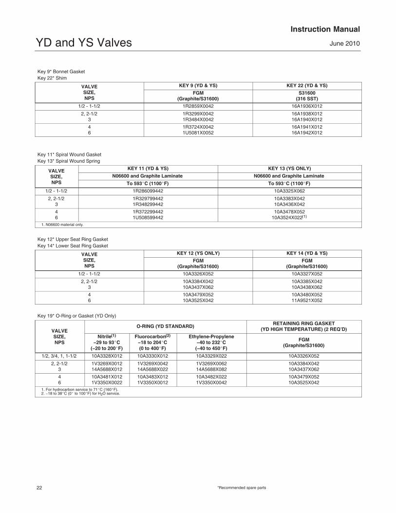
Key 9* Bonnet GasketKey 22* Shim
VALVESIZE,NPS
KEY 9 (YD & YS) KEY 22 (YD & YS)
FGM(Graphite/S31600)
S31600(316 SST)
1/2 - 1-1/2 1R2859X0042 16A1936X012
2, 2-1/23
1R3299X00421R3484X0042
16A1938X01216A1940X012
46
1R3724X00421U5081X0052
16A1941X01216A1942X012
Key 11* Spiral Wound GasketKey 13* Spiral Wound Spring
VALVESIZE,NPS
KEY 11 (YD & YS) KEY 13 (YS ONLY)
N06600 and Graphite Laminate N06600 and Graphite Laminate
To 593�C (1100�F) To 593�C (1100�F)
1/2 - 1-1/2 1R286099442 10A3325X062
2, 2-1/23
1R3297994421R348299442
10A3383X04210A3436X042
46
1R3722994421U508599442
10A3478X05210A3524X022(1)
1. N06600 material only.
Key 12* Upper Seat Ring GasketKey 14* Lower Seat Ring Gasket
VALVESIZE,NPS
KEY 12 (YS ONLY) KEY 14 (YD & YS)
FGM(Graphite/S31600)
FGM(Graphite/S31600)
1/2 - 1-1/2 10A3326X052 10A3327X052
2, 2-1/23
10A3384X04210A3437X062
10A3385X04210A3438X062
46
10A3479X05210A3525X042
10A3480X05211A9521X052
Key 19* O-Ring or Gasket (YD Only)
VALVESIZE,NPS
O-RING (YD STANDARD) RETAINING RING GASKET(YD HIGH TEMPERATURE) (2 REQ’D)
Nitrile(1)
�29 to 93�C(�20 to 200�F)
Fluorocarbon(2)
�18 to 204�C(0 to 400�F)
Ethylene-Propylene�40 to 232�C
(�40 to 450�F)
FGM(Graphite/S31600)
1/2, 3/4, 1, 1-1/2 10A3328X012 10A3330X012 10A3329X022 10A3326X052
2, 2-1/23
1V3269X001214A5688X012
1V3269X004214A5688X022
1V3269X006214A5688X082
10A3384X04210A3437X062
46
10A3481X0121V3350X0022
10A3483X0121V3350X0012
10A3482X0221V3350X0042
10A3479X05210A3525X042
1. For hydrocarbon service to 71�C (160�F).2. �18 to 38�C (0� to 100�F) for H2O service.
*Recommended spare parts

YD and YS ValvesInstruction Manual
June 2010
23
Keys 20*, 20A*, & 20B* Seals (YD Only)
VALVESIZE,NPS
YD (STANDARD) YD (HIGHTEMPERATURE)
Key 20ASeal Ring
Key 20BBack Up Ring
Key 20Valve Plug Seal
PTFENitrile(1)
�29 to 93�C(�20 to 200�F)
Fluorocarbon(2)
�18 to 204�C(0 to 400�F)
Ethylene Propylene�40 to 232�C
(�40 to 450�F)Graphite (2 req’d)
1/2, 3/4, 1, 1-1/2 10A3331X012 10A3332X022 10A3332X032 10A3332X042 10A3333X012
2, 2-1/23
10A3388X01210A3442X012
10A3389X02210A3443X022
10A3389X03210A3443X032
10A3389X05210A3443X072
10A3390X01210A3444X012
46
10A3484X01210A3530X012
10A3485X02210A3531X022
10A3485X03210A3531X032
10A3485X04210A3531X052
10A3486X01210A3532X012
1. For hydrocarbon service to 71�C (160�F).2. �18 to 38�C (0� to 100�F) for H2O service.
Keys 6*, 7*, 8, and 10 Packing Box Parts
DESCRIPTIONKEY
NUMBERSTEM DIAMETER, mm (INCHES)
9.5 (3/8) 12.7 (1/2) 19.1 (3/4) 25.4 (1)
PTFEV-RingPacking
Single packing set, PTFE(1 req’d for single, 2 req’d for double)
6 1R290001012 1R290201012 1R290401012 1R290601012
Spring, stainless steel (for single only) 8 1F125437012 1F125537012 1F125637012 1D582937012
Lantern Ring, stainless steel(for double only)
8 1F364135072 1J962335072 0N028435072 0U099735072
Quantity required Double � � � 1 2 1 1
Special washer, stainless steel(for single only)
10 1F125236042 1F125136042 1F125036042 1H982236042
PTFE/CompositionPacking
Packing Ring, PTFE/Composition 7 1F3370X0012 1E319001042 1E319101042 1D7518X0012
Quantity required Double � � � 7 10 8 8
Lantern Ring, stainless steel(1 required for double)
8 1F364135072 1J962335072 0N028435072 0U099735072
GraphiteRibbon/Packing
Packing Ring, graphite filament 7 1F3370X0322 1E3190X0222 1E3191X0282 1D7518X0132
Quantity required SingleDouble
� � �� � �
24
24
35
35
Packing ring, graphite ribbon 7 1V3160X0022 1V3802X0022 1V2396X0022 1U6768X0022
Quantity required SingleDouble
� � �� � �
23
23
23
23
Lantern ring, S31600 (316 SST) 8 1F364135702 1J962335072 0N028435072 0U099735072
Quantity required SingleDouble
� � �� � �
21
32
21
21
Bonnet for YD and YS1 Bonnet
If you need a bonnet as a replacement part,order by valve size and stem diameter, serialnumber, and desired material.
14 Pipe Plug16 Pipe Plug (Used With Tapped Extension Bonnet Only)
(not shown)27 Pipe Nipple (Used with Lubr./Iso. Valve)
ENVIRO-SEAL Bellows Seal Parts1 Bonnet/ENVIRO-SEAL bellows seal bonnet
If you need a bonnet or an ENVIRO-SEAL bellows sealbonnet as a replacement part, order by valve size and stem
diameter, serial number, and desired material.
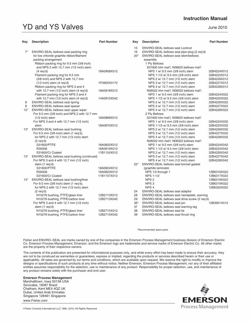
Key Description Part Number
3 ENVIRO-SEAL bellows seal packing flange4 ENVIRO-SEAL bellows seal stud bolt5 ENVIRO-SEAL bellows seal hex nut6* ENVIRO-SEAL bellows seal packing set
PTFE for 9.5 mm (3/8 inch) stem (1 req’dfor single packing, 2 req’d for doublepacking) 12A9016X012
PTFE for NPS 2 with 12.7 mm (1/2 inch)stem (2 req’d for double packing) 12A9016X012
PTFE for NPS 3 and 4 with 12.7 mm(1/2 inch) stem (2 req’d for doublepacking) 12A8832X012
*Recommended spare parts
YD and YS ValvesInstruction Manual
June 2010
24
Key Description Part Number
7* ENVIRO-SEAL bellows seal packing ringfor low chloride graphite ribbon/filamentpacking arrangementRibbon packing ring for 9.5 mm (3/8 inch)and NPS 2 with 12.7 mm (1/2 inch) stem(4 req’d) 18A0908X012
Filament packing ring for 9.5 mm(3/8 inch) and NPS 2 with 12.7 mm(1/2 inch) stem (4 req’d) 1P3905X0172
Ribbon packing ring for NPS 3 and 4with 12.7 mm (1/2 inch) stem (4 req’d) 18A0918X012
Filament packing ring for NPS 3 and 4with 12.7 mm (1/2 inch) stem (4 req’d) 14A0915X042
8 ENVIRO-SEAL bellows seal spring8 ENVIRO-SEAL bellows seal spacer
12* ENVIRO-SEAL bellows seal upper wiperFor 9.5 mm (3/8 inch) and NPS 2 with 12.7 mm(1/2 inch) stem 18A0868X012
For NPS 3 and 4 with 12.7 mm (1/2 inch)stem 18A0870X012
13* ENVIRO-SEAL bellows seal bushingFor 9.5 mm (3/8 inch) stem (1 req’d),for NPS 2 with 12.7 mm (1/2 inch) stem(2 req’d)S31600/PTFE 18A0820X012R30006 18A0819X012S31600/Cr Coated 11B1155X012
13* ENVIRO-SEAL bellows seal bushing (continued)For NPS 3 and 4 with 12.7 mm (1/2 inch)stem (1 req’d)S31600/PTFE 18A0824X012R30006 18A0823X012S31600/Cr Coated 11B1157X012
13* ENVIRO-SEAL bellows seal bushing/linerFor 9.5 mm (3/8 inch) stem (1 req’d),for NPS 2 with 12.7 mm (1/2 inch) stem(2 req’d)N10276 bushing, PTFE/glass liner 12B2713X012N10276 bushing, PTFE/carbon liner 12B2713X042
For NPS 3 and 4 with 12.7 mm (1/2 inch)stem (1 req’d)N10276 bushing, PTFE/glass liner 12B2715X012N10276 bushing, PTFE/carbon liner 12B2715X042
Key Description Part Number
15 ENVIRO-SEAL bellows seal Locknut16 ENVIRO-SEAL bellows seal pipe plug (2 req’d)20* ENVIRO-SEAL bellows seal stem/bellows
assembly1 Ply BellowsS31600 trim mat’l, N06625 bellows mat’lNPS 1 w/ 9.5 mm (3/8 inch) stem 32B4224X012NPS 1-1/2 w/ 9.5 mm (3/8 inch) stem 32B4225X012NPS 2 w/ 12.7 mm (1/2 inch) stem 32B4226X012NPS 3 w/ 12.7 mm (1/2 inch) stem 32B4227X012NPS 4 w/ 12.7 mm (1/2 inch) stem 32B4228X012
N06022 trim mat’l, N06022 bellows mat’lNPS 1 w/ 9.5 mm (3/8 inch) stem 32B4224X022NPS 1-1/2 w/ 9.5 mm (3/8 inch) stem 32B4225X022NPS 2 w/ 12.7 mm (1/2 inch) stem 32B4226X022NPS 3 w/ 12.7 mm (1/2 inch) stem 32B4227X022NPS 4 w/ 12.7 mm (1/2 inch) stem 32B4228X022
2 Ply BellowsS31600 trim mat’l, N06625 bellows mat’lNPS 1 w/ 9.5 mm (3/8 inch) stem 32B4224X032NPS 1-1/2 w/ 9.5 mm (3/8 inch) stem 32B4225X032NPS 2 w/ 12.7 mm (1/2 inch) stem 32B4226X032NPS 3 w/ 12.7 mm (1/2 inch) stem 32B4227X032NPS 4 w/ 12.7 mm (1/2 inch) stem 32B4228X032
N06022 trim mat’l, N06022 bellows mat’lNPS 1 w/ 9.5 mm (3/8 inch) stem 32B4224X042NPS 1-1/2 w/ 9.5 mm (3/8 inch) stem 32B4225X042NPS 2 w/ 12.7 mm (1/2 inch) stem 32B4226X042NPS 3 w/ 12.7 mm (1/2 inch) stem 32B4227X042NPS 4 w/ 12.7 mm (1/2 inch) stem 32B4228X042
22* ENVIRO-SEAL bellows seal bonnet gasket(graphite laminate)NPS 1/2 through 1 12B6316X022NPS 1-1/2 12B6317X022NPS 2 12B6318X022NPS 3 12B6319X022NPS 4 12B6320X022
24 ENVIRO-SEAL bellows seal adaptor28 ENVIRO-SEAL bellows seal nameplate, warning29 ENVIRO-SEAL bellows seal drive screw (2 req’d)36* ENVIRO-SEAL bellows seal pin 12B3951X01237 ENVIRO-SEAL bellows seal warning tag38 ENVIRO-SEAL bellows seal tie39 ENVIRO-SEAL bellows seal thrust ring
*Recommended spare parts
Emerson Process Management Marshalltown, Iowa 50158 USASorocaba, 18087 BrazilChatham, Kent ME4 4QZ UKDubai, United Arab EmiratesSingapore 128461 Singaporewww.Fisher.com
The contents of this publication are presented for informational purposes only, and while every effort has been made to ensure their accuracy, theyare not to be construed as warranties or guarantees, express or implied, regarding the products or services described herein or their use orapplicability. All sales are governed by our terms and conditions, which are available upon request. We reserve the right to modify or improve thedesigns or specifications of such products at any time without notice. Neither Emerson, Emerson Process Management, nor any of their affiliatedentities assumes responsibility for the selection, use or maintenance of any product. Responsibility for proper selection, use, and maintenance ofany product remains solely with the purchaser and end user.
�Fisher Controls International LLC 1990, 2010; All Rights Reserved
Fisher and ENVIRO�SEAL are marks owned by one of the companies in the Emerson Process Management business division of Emerson ElectricCo. Emerson Process Management, Emerson, and the Emerson logo are trademarks and service marks of Emerson Electric Co. All other marksare the property of their respective owners.