fish passage planning and design - james cook university · fish passage planning and design ....
TRANSCRIPT
Culvert Fishway Planning and Design GuidelinesPart G – Baffle Fishways for Pipe Culverts
Ross Kapitzke James Cook University School of Engineering and Physical Sciences
April 2010 – VER2.0
Fish Passage Planning and Design
VER2.0 -/04/10
School of Engineering and Physical Sciences • Ross Kapitzke • fishways\G_baffle fishways for pipe culverts -/4/10 G-i
Culvert fishway guidelines: Part G – Baffle fishways for pipe culverts
James Cook University School of Engineering and Physical Sciences Culvert Fishway Planning and Design Guidelines Part G – Baffle Fishways for Pipe Culverts Contents
1 INTRODUCTION 1
2 FISH MIGRATION BARRIER PROBLEMS AND BAFFLE FISHWAY DESIGNS 2 2.1 Fish migration barrier problems for pipe culverts 2 2.2 Baffle fishway designs for pipe culverts 3
3 OFFSET BAFFLE FISHWAY DESIGN FOR PIPE CULVERTS 6 3.1 Design concept and configuration for offset baffle fishway 6 3.2 Hydraulic performance characteristics of offset baffle fishway 9 3.3 Fish passage characteristics of offset baffle fishway 10 3.4 Conveyance, sediment and maintenance characteristics of offset baffle fishway 12
4 CORNER “QUAD” BAFFLE FISHWAY DESIGN FOR PIPE CULVERTS 14 4.1 Design concept and configuration for corner “Quad” baffle fishway 14 4.2 Hydraulic performance characteristics of corner “Quad” baffle fishway 17 4.3 Fish passage characteristics of corner “Quad” baffle fishway 19 4.4 Conveyance, sediment and maintenance characteristics of “Quad” baffle fishway 20
5 OVERALL SUITABILITY OF BAFFLE FISHWAY DESIGNS 22
6 BIBLIOGRAPHY 24
APPENDIX G1 – SOLANDER ROAD PROTOTYPE OFFSET AND CORNER BAFFLE FISHWAYS 1
VER2.0 -/04/10
School of Engineering and Physical Sciences • Ross Kapitzke • fishways\G_baffle fishways for pipe culverts -/4/10 G-1
Culvert fishway guidelines: Part G – Baffle fishways for pipe culverts
James Cook University School of Engineering and Physical Sciences Culvert Fishway Planning and Design Guidelines Part G – Baffle Fishways for Pipe Culverts
1 INTRODUCTION
Where provisions for fish passage are to be made at pipe culvert waterway crossings, designers, managers and scientists require information on fishway design options for pipe culverts, and the configuration and performance characteristics of fish passage devices such as baffle fishways.
These Guidelines Part G present the baffle fishway designs for pipe culverts, and aim to:
identify baffle fishway design options to suit particular hydraulic barriers to fish passage at pipe culverts, and describe relevant culvert fishway configurations and characteristics
consider relevant design concepts and background, and general configuration and performance characteristics of baffle type fishways applying for pipe culverts (see Guideline Part F – Baffle Fishways for Box Culverts)
outline design concepts, configurations and performance characteristics for the offset baffle fishway and the corner “Quad” baffle fishway for pipe culverts
illustrate baffle fishway design for pipe culverts through the University Creek Solander Road case study project
summarise findings of the field prototype and laboratory model testing of the offset baffle and corner “Quad” baffle fishway designs for pipe culverts (Appendix G1)
The information from Guidelines Part G is used in other parts of these Guidelines to:
guide the selection of fishway devices to meet fish passage requirements for pipe culverts (Part C – Fish Migration Barriers and Fish Passage Options for Road Crossings)
guide the design configurations for fishway facilities in pipe culvert waterway crossings incorporating baffle fishways (Part E – Fish Passage Design: Site Scale)
These Guidelines deal primarily with the Concept and Preliminary Design phases of planning and design procedures for road and other infrastructure projects. They apply to design of fish passage facilities to mitigate potential fish migration barrier impacts at new structures, and also to remediation measures to overcome barriers by retrofit at existing structures (Box G1.1).
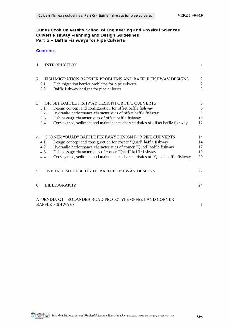
Box G1.1: Baffle fishway facilities for pipe culverts established at the Solander Road crossing of University Creek in Townsville (Source: Ross Kapitzke)
Glass perch moving through offset baffle fishway – schooling at downstream end within prototype fishway support cradle
(28/01/06)
Plotosid catfish moving through corner “Quad” baffle fishway – resting between
prototype fishway baffles at downstream end (09/04/06)
VER2.0 -/04/10
School of Engineering and Physical Sciences • Ross Kapitzke • fishways\G_baffle fishways for pipe culverts -/4/10 G-2
Culvert fishway guidelines: Part G – Baffle fishways for pipe culverts
2 FISH MIGRATION BARRIER PROBLEMS AND BAFFLE FISHWAY DESIGNS
Pipe culverts are used extensively for waterway drainage crossings in Australia, most commonly for small streams. Single or multiple barrel culverts of from 1.2 m to 3 m diameter are often used at roads ranging from narrow tracks with culvert lengths of less than 4 m, to multiple carriageway highways with culvert lengths of up to 60 m. Pipe culverts are sometimes built into causeway structures, which overtop during stream flows in excess of pipe full capacity. Fish migration barrier problems commonly occur at pipe culvert crossings, as they are conventionally designed with a focus on drainage, transport and utility functions, and commonly experience high velocity and other adverse hydraulic conditions that impact on fish movement.
Fish migration barrier problems at pipe culvert crossings can be addressed through use of baffle fishway devices in conjunction with other fishway components to mitigate impacts for new developments or remediate barrier effects through retrofit at existing structures. Many of the principles for use of baffle fishways at pipe culverts are common to the principles applying for baffle fishways in box culverts. In addition to specific information on baffle fishway designs for pipe culverts presented in this Guideline Part G – Baffle Fishways for Pipe Culverts, general information on design concepts and background, configuration aspects and hydraulic and fish passage performance characteristics of baffle fishways for box culvert and pipe culvert waterway crossings are outlined in Guidelines Part F – Baffle Fishways for Box Culverts.
This chapter briefly outlines common fish migration barrier problems at pipe culvert structures and introduces the general aspects of baffle fishway designs to overcome these barriers. Illustrations of fish migration barriers and mitigation / remediation design using baffle fishway devices are provided in this chapter and in subsequent chapters for the Solander Road pipe culvert crossing of University Creek in Townsville (Box G2.1), where the offset baffle and corner “Quad” baffle prototype fishway designs have been implemented as retrofits (Kapitzke 2007c).
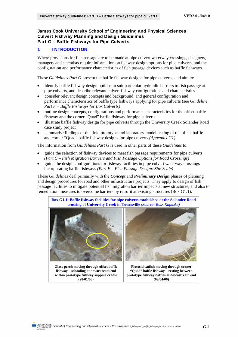
Box G2.1: Solander Road pipe culvert crossing of University Creek (Source: Ross Kapitzke)
Pipe culvert in relatively steep gradient stream reach - erosion downstream (24/03/05)
Fish migration barrier problems at pipe barrel and culvert outlet (-/02/02)
2.1 Fish migration barrier problems for pipe culverts
Fish migration barriers at a pipe culvert waterway crossing may be associated with adverse hydraulic conditions within a number of zones of the culvert structure, including the downstream channel, culvert outlet, culvert barrel and culvert inlet (see Guidelines Part C – Fish Migration Barriers and Fish Passage Options for Road Crossings). Migration barriers may also be associated with overtopping of a causeway section during higher flows at the crossing. The nature of the stream, the location of the waterway crossing on the stream, and the configuration of the culvert / causeway structure at the site determine the extent to which a pipe culvert crossing presents a barrier to upstream fish migration.
VER2.0 -/04/10
School of Engineering and Physical Sciences • Ross Kapitzke • fishways\G_baffle fishways for pipe culverts -/4/10 G-3
Culvert fishway guidelines: Part G – Baffle fishways for pipe culverts
High velocities within the culvert barrel are common features of pipe culvert crossings due to the regular smooth sided nature of the pipe, the relatively steep slopes that are often used for pipe culverts, and the concentrated flow that occurs through the culvert barrel. The setting of the culvert structure at the site and within the stream reach may also contribute to a water surface drop at the culvert outlet, which is another major factor that may present a barrier to fish migration. A perched culvert outlet and associated water surface drop, where the pipe invert or downstream culvert apron is raised above the stream channel bed, are common in pipe culverts installed in relatively steep gradient (upland) stream reaches and at riffle (high point) locations. Although less common than for box culverts, pipe culverts installed at flatter gradient (lowland) sites may have submerged pipe inverts, which as a result of downstream ponding in the waterway, do not produce water surface drops that represent fish migration barriers.
Pipe culvert designs are commonly configured so that the culvert invert initially coincides with the nominal stream bed level at the crossing site, but the pipe outlet and culvert outlet apron may become perched over time as a result of downstream bed erosion. A pipe invert gradient of up to 3 % is commonly used in Australian culvert crossing structures, and although this may be set to initially coincide with the nominal stream gradient at the site, erosion as a result of the high culvert velocities and erodible stream reaches may lead to a perched outlet with locally steeper gradients at the erosion hole. These erosion processes contribute to adverse hydraulic conditions that are to be overcome to provide for fish passage at the waterway structure.
For example, the Solander Road pipe culvert / causeway crossing, which is located at a local high point in a relatively steep gradient (1 in 100) reach of University Creek, produces high velocity flows through the culvert and over the causeway that cause severe hydraulic conditions for fish. These high energy flows, in combination with low tailwater levels, have contributed to bed and bank erosion at the culvert outlet, undermining the culvert structure and contributing further to adverse hydraulic conditions for fish passage through the crossing (Box G2.1).
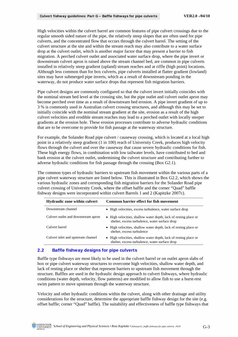
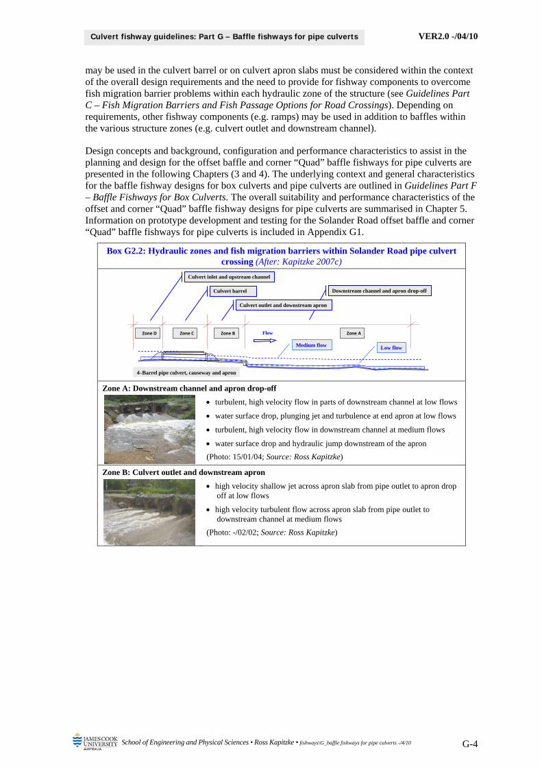
The common types of hydraulic barriers to upstream fish movement within the various parts of a pipe culvert waterway structure are listed below. This is illustrated in Box G2.2, which shows the various hydraulic zones and corresponding fish migration barriers for the Solander Road pipe culvert crossing of University Creek, where the offset baffle and the corner “Quad” baffle fishway designs were incorporated within culvert Barrels 1 and 2 (Kapitzke 2007c).
Hydraulic zone within culvert Common barrier effect for fish movement
Downstream channel High velocities, excess turbulence, water surface drop
Culvert outlet and downstream apron High velocities, shallow water depth, lack of resting place or shelter, excess turbulence, water surface drop
Culvert barrel High velocities, shallow water depth, lack of resting place or shelter, excess turbulence
Culvert inlet and upstream channel High velocities, shallow water depth, lack of resting place or shelter, excess turbulence, water surface drop
2.2 Baffle fishway designs for pipe culverts
Baffle type fishways are most likely to be used in the culvert barrel or on outlet apron slabs of box or pipe culvert waterway structures to overcome high velocities, shallow water depth, and lack of resting place or shelter that represent barriers to upstream fish movement through the structure. Baffles are used in the hydraulic design approach to culvert fishways, where hydraulic conditions (water depth, velocity, flow patterns) are modified to allow fish to use a burst-rest swim pattern to move upstream through the waterway structure.
Velocity and other hydraulic conditions within the culvert, along with other drainage and utility considerations for the structure, determine the appropriate baffle fishway design for the site (e.g. offset baffle; corner “Quad” baffle). The suitability and effectiveness of baffle type fishways that
VER2.0 -/04/10
School of Engineering and Physical Sciences • Ross Kapitzke • fishways\G_baffle fishways for pipe culverts -/4/10 G-4
Culvert fishway guidelines: Part G – Baffle fishways for pipe culverts
may be used in the culvert barrel or on culvert apron slabs must be considered within the context of the overall design requirements and the need to provide for fishway components to overcome fish migration barrier problems within each hydraulic zone of the structure (see Guidelines Part C – Fish Migration Barriers and Fish Passage Options for Road Crossings). Depending on requirements, other fishway components (e.g. ramps) may be used in addition to baffles within the various structure zones (e.g. culvert outlet and downstream channel).
Design concepts and background, configuration and performance characteristics to assist in the planning and design for the offset baffle and corner “Quad” baffle fishways for pipe culverts are presented in the following Chapters (3 and 4). The underlying context and general characteristics for the baffle fishway designs for box culverts and pipe culverts are outlined in Guidelines Part F – Baffle Fishways for Box Culverts. The overall suitability and performance characteristics of the offset and corner “Quad” baffle fishway designs for pipe culverts are summarised in Chapter 5. Information on prototype development and testing for the Solander Road offset baffle and corner “Quad” baffle fishways for pipe culverts is included in Appendix G1.
Box G2.2: Hydraulic zones and fish migration barriers within Solander Road pipe culvert crossing (After: Kapitzke 2007c)
Zone A: Downstream channel and apron drop-off
turbulent, high velocity flow in parts of downstream channel at low flows
water surface drop, plunging jet and turbulence at end apron at low flows
turbulent, high velocity flow in downstream channel at medium flows
water surface drop and hydraulic jump downstream of the apron
(Photo: 15/01/04; Source: Ross Kapitzke)
Zone B: Culvert outlet and downstream apron
high velocity shallow jet across apron slab from pipe outlet to apron drop off at low flows
high velocity turbulent flow across apron slab from pipe outlet to downstream channel at medium flows
(Photo: -/02/02; Source: Ross Kapitzke)
Culvert inlet and upstream channel
Culvert barrel Downstream channel and apron drop-off
Culvert outlet and downstream apron
Zone D Zone C Zone B Zone A
4–Barrel pipe culvert, causeway and apron
Flow
Low flow Medium flow

VER2.0 -/04/10
School of Engineering and Physical Sciences • Ross Kapitzke • fishways\G_baffle fishways for pipe culverts -/4/10 G-5
Culvert fishway guidelines: Part G – Baffle fishways for pipe culverts
Box G2.2: Hydraulic zones and fish migration barriers within Solander Road pipe culvert crossing (After: Kapitzke 2007c)
Zone C: Culvert barrel
high velocity jet with excess turbulence and no resting points within the culvert barrel for low flows
high velocity jet with excess turbulence and no resting points within the culvert barrel for medium flows
(Photo: -/02/02; Source: Ross Kapitzke)
Zone D: Culvert inlet and upstream channel
turbulent, high velocity flow at pipe and upstream channel for low flows
lack of shelter zones upstream of culvert and constricted flow tending to sweep fish back into pipe at low flows
ponded but constricted flow upstream of culvert with high velocity zones at pipe inlet tending to sweep fish back into pipe at medium flows
(Photo: 15/01/04; Source: Ross Kapitzke)
VER2.0 -/04/10
School of Engineering and Physical Sciences • Ross Kapitzke • fishways\G_baffle fishways for pipe culverts -/4/10 G-6
Culvert fishway guidelines: Part G – Baffle fishways for pipe culverts
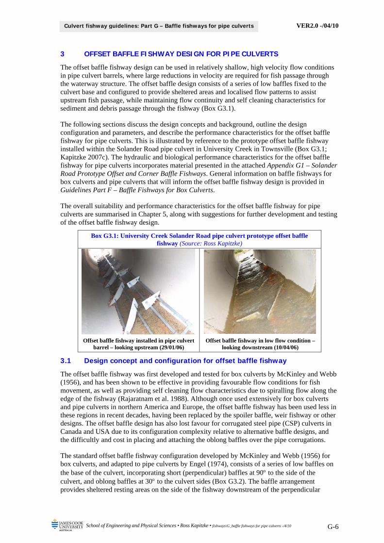
3 OFFSET BAFFLE FISHWAY DESIGN FOR PIPE CULVERTS
The offset baffle fishway design can be used in relatively shallow, high velocity flow conditions in pipe culvert barrels, where large reductions in velocity are required for fish passage through the waterway structure. The offset baffle design consists of a series of low baffles fixed to the culvert base and configured to provide sheltered areas and localised flow patterns to assist upstream fish passage, while maintaining flow continuity and self cleaning characteristics for sediment and debris passage through the fishway (Box G3.1).
The following sections discuss the design concepts and background, outline the design configuration and parameters, and describe the performance characteristics for the offset baffle fishway for pipe culverts. This is illustrated by reference to the prototype offset baffle fishway installed within the Solander Road pipe culvert in University Creek in Townsville (Box G3.1; Kapitzke 2007c). The hydraulic and biological performance characteristics for the offset baffle fishway for pipe culverts incorporates material presented in the attached Appendix G1 – Solander Road Prototype Offset and Corner Baffle Fishways. General information on baffle fishways for box culverts and pipe culverts that will inform the offset baffle fishway design is provided in Guidelines Part F – Baffle Fishways for Box Culverts.
The overall suitability and performance characteristics for the offset baffle fishway for pipe culverts are summarised in Chapter 5, along with suggestions for further development and testing of the offset baffle fishway design.
Box G3.1: University Creek Solander Road pipe culvert prototype offset baffle fishway (Source: Ross Kapitzke)
Offset baffle fishway installed in pipe culvert barrel – looking upstream (29/01/06)
Offset baffle fishway in low flow condition – looking downstream (10/04/06)
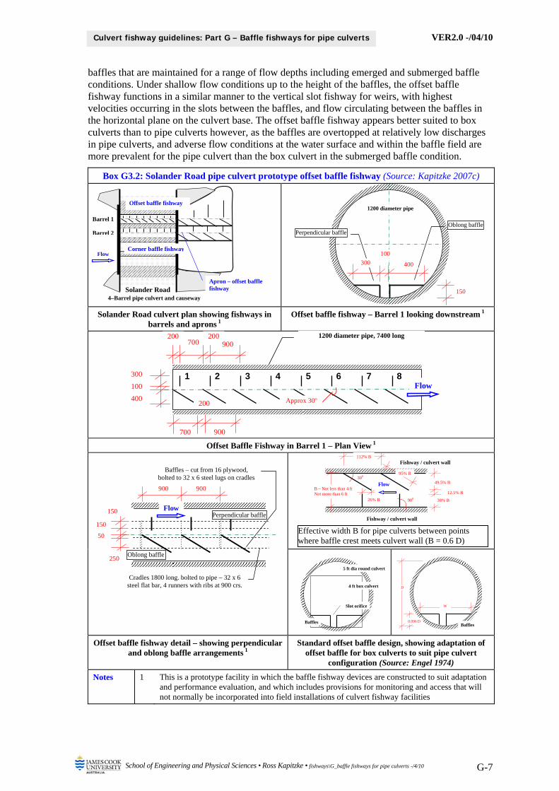
3.1 Design concept and configuration for offset baffle fishway
The offset baffle fishway was first developed and tested for box culverts by McKinley and Webb (1956), and has been shown to be effective in providing favourable flow conditions for fish movement, as well as providing self cleaning flow characteristics due to spiralling flow along the edge of the fishway (Rajaratnam et al. 1988). Although once used extensively for box culverts and pipe culverts in northern America and Europe, the offset baffle fishway has been used less in these regions in recent decades, having been replaced by the spoiler baffle, weir fishway or other designs. The offset baffle design has also lost favour for corrugated steel pipe (CSP) culverts in Canada and USA due to its configuration complexity relative to alternative baffle designs, and the difficultly and cost in placing and attaching the oblong baffles over the pipe corrugations.
The standard offset baffle fishway configuration developed by McKinley and Webb (1956) for box culverts, and adapted to pipe culverts by Engel (1974), consists of a series of low baffles on the base of the culvert, incorporating short (perpendicular) baffles at 90 to the side of the culvert, and oblong baffles at 30 to the culvert sides (Box G3.2). The baffle arrangement provides sheltered resting areas on the side of the fishway downstream of the perpendicular
VER2.0 -/04/10
School of Engineering and Physical Sciences • Ross Kapitzke • fishways\G_baffle fishways for pipe culverts -/4/10 G-7
Culvert fishway guidelines: Part G – Baffle fishways for pipe culverts
baffles that are maintained for a range of flow depths including emerged and submerged baffle conditions. Under shallow flow conditions up to the height of the baffles, the offset baffle fishway functions in a similar manner to the vertical slot fishway for weirs, with highest velocities occurring in the slots between the baffles, and flow circulating between the baffles in the horizontal plane on the culvert base. The offset baffle fishway appears better suited to box culverts than to pipe culverts however, as the baffles are overtopped at relatively low discharges in pipe culverts, and adverse flow conditions at the water surface and within the baffle field are more prevalent for the pipe culvert than the box culvert in the submerged baffle condition.
Box G3.2: Solander Road pipe culvert prototype offset baffle fishway (Source: Kapitzke 2007c)
Solander Road culvert plan showing fishways in barrels and aprons 1
Offset baffle fishway – Barrel 1 looking downstream 1
Offset Baffle Fishway in Barrel 1 – Plan View 1
Offset baffle fishway detail – showing perpendicular and oblong baffle arrangements 1
Standard offset baffle design, showing adaptation of offset baffle for box culverts to suit pipe culvert
configuration (Source: Engel 1974)
Notes 1 This is a prototype facility in which the baffle fishway devices are constructed to suit adaptation and performance evaluation, and which includes provisions for monitoring and access that will not normally be incorporated into field installations of culvert fishway facilities
Solander Road4–Barrel pipe culvert and causeway
Corner baffle fishway
Offset baffle fishway
Apron – offset baffle fishway
Barrel 1
Barrel 2
Flow
Oblong bafflePerpendicular baffle
150
400
100
300
1200 diameter pipe
1 2 3 4 5 6 7 8
700 200 200
Flow
400
100
300
900
700
200
900
1200 diameter pipe, 7400 long
Approx 30
900
250
150
150
900
50
Perpendicular baffle
Oblong baffle
Baffles – cut from 16 plywood, bolted to 32 x 6 steel lugs on cradles
Cradles 1800 long. bolted to pipe – 32 x 6 steel flat bar, 4 runners with ribs at 900 crs.
Flow
Effective width B for pipe culverts between points where baffle crest meets culvert wall (B = 0.6 D)
Flow 49.5% B
Fishway / culvert wall
300
900
12.5% B
38% B 26% B
112% B
B – Not less than 4 ft Not more than 6 ft
95% B
Fishway / culvert wall
W
Baffles 0.096 D
D
5 ft dia round culvert
4 ft box culvert
Baffles
Slot orifice
VER2.0 -/04/10
School of Engineering and Physical Sciences • Ross Kapitzke • fishways\G_baffle fishways for pipe culverts -/4/10 G-8
Culvert fishway guidelines: Part G – Baffle fishways for pipe culverts
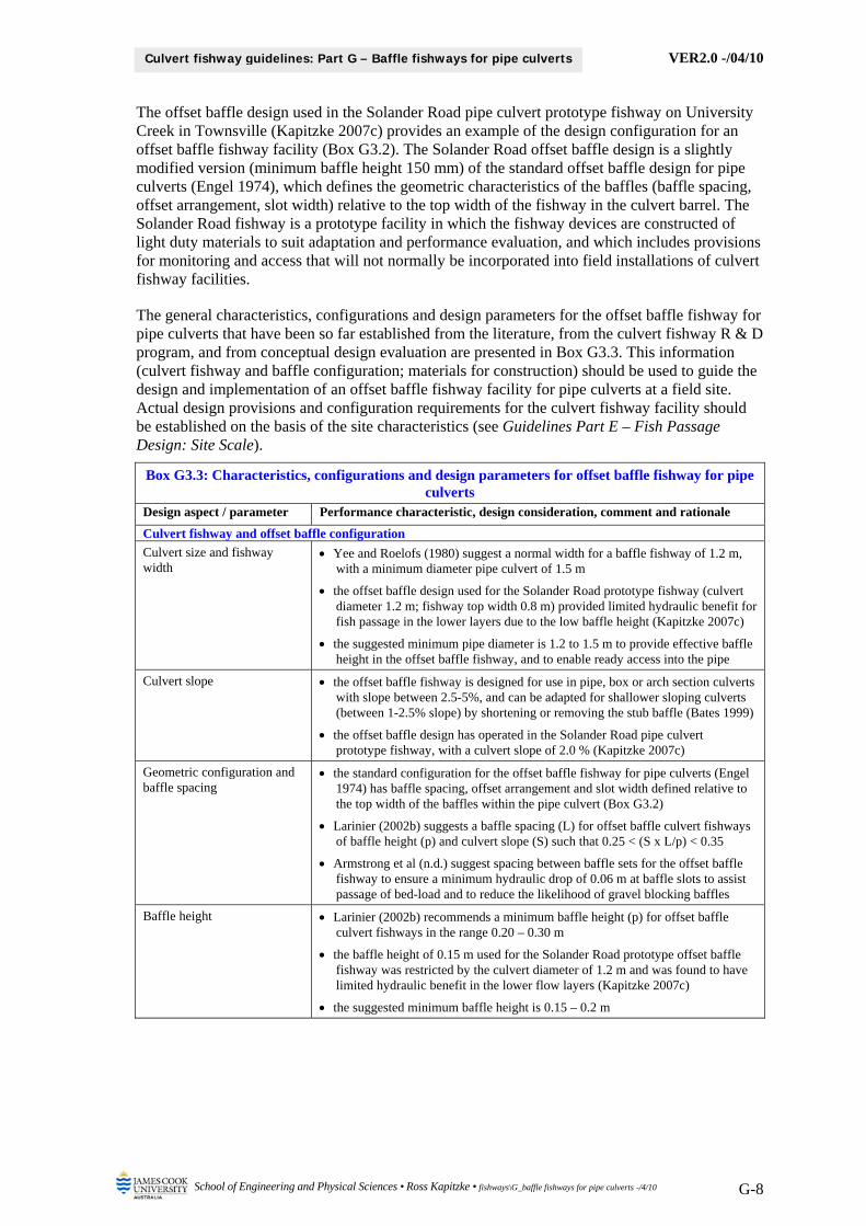
The offset baffle design used in the Solander Road pipe culvert prototype fishway on University Creek in Townsville (Kapitzke 2007c) provides an example of the design configuration for an offset baffle fishway facility (Box G3.2). The Solander Road offset baffle design is a slightly modified version (minimum baffle height 150 mm) of the standard offset baffle design for pipe culverts (Engel 1974), which defines the geometric characteristics of the baffles (baffle spacing, offset arrangement, slot width) relative to the top width of the fishway in the culvert barrel. The Solander Road fishway is a prototype facility in which the fishway devices are constructed of light duty materials to suit adaptation and performance evaluation, and which includes provisions for monitoring and access that will not normally be incorporated into field installations of culvert fishway facilities.
The general characteristics, configurations and design parameters for the offset baffle fishway for pipe culverts that have been so far established from the literature, from the culvert fishway R & D program, and from conceptual design evaluation are presented in Box G3.3. This information (culvert fishway and baffle configuration; materials for construction) should be used to guide the design and implementation of an offset baffle fishway facility for pipe culverts at a field site. Actual design provisions and configuration requirements for the culvert fishway facility should be established on the basis of the site characteristics (see Guidelines Part E – Fish Passage Design: Site Scale).
Box G3.3: Characteristics, configurations and design parameters for offset baffle fishway for pipe culverts
Design aspect / parameter Performance characteristic, design consideration, comment and rationale
Culvert fishway and offset baffle configuration
Culvert size and fishway width
Yee and Roelofs (1980) suggest a normal width for a baffle fishway of 1.2 m, with a minimum diameter pipe culvert of 1.5 m
the offset baffle design used for the Solander Road prototype fishway (culvert diameter 1.2 m; fishway top width 0.8 m) provided limited hydraulic benefit for fish passage in the lower layers due to the low baffle height (Kapitzke 2007c)
the suggested minimum pipe diameter is 1.2 to 1.5 m to provide effective baffle height in the offset baffle fishway, and to enable ready access into the pipe
Culvert slope the offset baffle fishway is designed for use in pipe, box or arch section culverts with slope between 2.5-5%, and can be adapted for shallower sloping culverts (between 1-2.5% slope) by shortening or removing the stub baffle (Bates 1999)
the offset baffle design has operated in the Solander Road pipe culvert prototype fishway, with a culvert slope of 2.0 % (Kapitzke 2007c)
Geometric configuration and baffle spacing
the standard configuration for the offset baffle fishway for pipe culverts (Engel 1974) has baffle spacing, offset arrangement and slot width defined relative to the top width of the baffles within the pipe culvert (Box G3.2)
Larinier (2002b) suggests a baffle spacing (L) for offset baffle culvert fishways of baffle height (p) and culvert slope (S) such that 0.25 < (S x L/p) < 0.35
Armstrong et al (n.d.) suggest spacing between baffle sets for the offset baffle fishway to ensure a minimum hydraulic drop of 0.06 m at baffle slots to assist passage of bed-load and to reduce the likelihood of gravel blocking baffles
Baffle height Larinier (2002b) recommends a minimum baffle height (p) for offset baffle culvert fishways in the range 0.20 – 0.30 m
the baffle height of 0.15 m used for the Solander Road prototype offset baffle fishway was restricted by the culvert diameter of 1.2 m and was found to have limited hydraulic benefit in the lower flow layers (Kapitzke 2007c)
the suggested minimum baffle height is 0.15 – 0.2 m
VER2.0 -/04/10
School of Engineering and Physical Sciences • Ross Kapitzke • fishways\G_baffle fishways for pipe culverts -/4/10 G-9
Culvert fishway guidelines: Part G – Baffle fishways for pipe culverts
Box G3.3: Characteristics, configurations and design parameters for offset baffle fishway for pipe culverts
Design aspect / parameter Performance characteristic, design consideration, comment and rationale
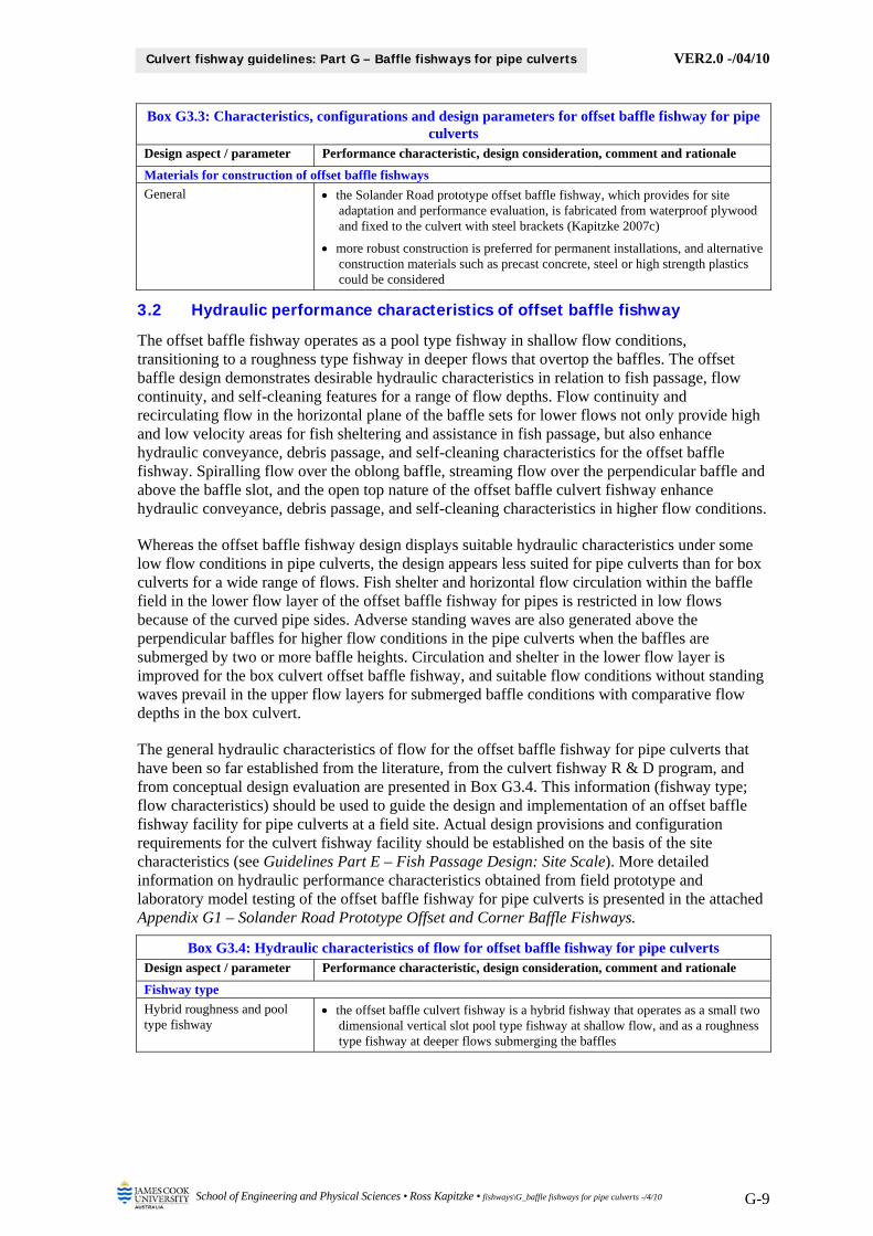
Materials for construction of offset baffle fishways
General the Solander Road prototype offset baffle fishway, which provides for site adaptation and performance evaluation, is fabricated from waterproof plywood and fixed to the culvert with steel brackets (Kapitzke 2007c)
more robust construction is preferred for permanent installations, and alternative construction materials such as precast concrete, steel or high strength plastics could be considered
3.2 Hydraulic performance characteristics of offset baffle fishway
The offset baffle fishway operates as a pool type fishway in shallow flow conditions, transitioning to a roughness type fishway in deeper flows that overtop the baffles. The offset baffle design demonstrates desirable hydraulic characteristics in relation to fish passage, flow continuity, and self-cleaning features for a range of flow depths. Flow continuity and recirculating flow in the horizontal plane of the baffle sets for lower flows not only provide high and low velocity areas for fish sheltering and assistance in fish passage, but also enhance hydraulic conveyance, debris passage, and self-cleaning characteristics for the offset baffle fishway. Spiralling flow over the oblong baffle, streaming flow over the perpendicular baffle and above the baffle slot, and the open top nature of the offset baffle culvert fishway enhance hydraulic conveyance, debris passage, and self-cleaning characteristics in higher flow conditions.
Whereas the offset baffle fishway design displays suitable hydraulic characteristics under some low flow conditions in pipe culverts, the design appears less suited for pipe culverts than for box culverts for a wide range of flows. Fish shelter and horizontal flow circulation within the baffle field in the lower flow layer of the offset baffle fishway for pipes is restricted in low flows because of the curved pipe sides. Adverse standing waves are also generated above the perpendicular baffles for higher flow conditions in the pipe culverts when the baffles are submerged by two or more baffle heights. Circulation and shelter in the lower flow layer is improved for the box culvert offset baffle fishway, and suitable flow conditions without standing waves prevail in the upper flow layers for submerged baffle conditions with comparative flow depths in the box culvert.
The general hydraulic characteristics of flow for the offset baffle fishway for pipe culverts that have been so far established from the literature, from the culvert fishway R & D program, and from conceptual design evaluation are presented in Box G3.4. This information (fishway type; flow characteristics) should be used to guide the design and implementation of an offset baffle fishway facility for pipe culverts at a field site. Actual design provisions and configuration requirements for the culvert fishway facility should be established on the basis of the site characteristics (see Guidelines Part E – Fish Passage Design: Site Scale). More detailed information on hydraulic performance characteristics obtained from field prototype and laboratory model testing of the offset baffle fishway for pipe culverts is presented in the attached Appendix G1 – Solander Road Prototype Offset and Corner Baffle Fishways.
Box G3.4: Hydraulic characteristics of flow for offset baffle fishway for pipe culverts Design aspect / parameter Performance characteristic, design consideration, comment and rationale
Fishway type
Hybrid roughness and pool type fishway
the offset baffle culvert fishway is a hybrid fishway that operates as a small two dimensional vertical slot pool type fishway at shallow flow, and as a roughness type fishway at deeper flows submerging the baffles
VER2.0 -/04/10
School of Engineering and Physical Sciences • Ross Kapitzke • fishways\G_baffle fishways for pipe culverts -/4/10 G-10
Culvert fishway guidelines: Part G – Baffle fishways for pipe culverts
Box G3.4: Hydraulic characteristics of flow for offset baffle fishway for pipe culverts Design aspect / parameter Performance characteristic, design consideration, comment and rationale
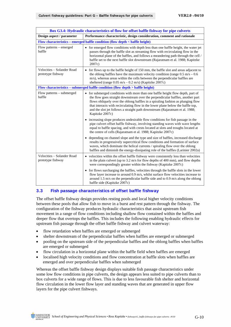
Flow characteristics – emerged baffle condition (flow depth < baffle height)
Flow patterns – emerged baffle
for emerged flow conditions with depth less than one baffle height, the water jet passes through the baffle slot as streaming flow with recirculating flow in the horizontal plane of the baffles, and follows a meandering path through the cell / baffle set to the next baffle slot downstream (Rajaratnam et al. 1988; Kapitzke 2007c)
Velocities – Solander Road prototype fishway
for flows up to the baffle height of 150 mm, the baffle slot and areas adjacent to the oblong baffles have the maximum velocity condition (range 0.5 m/s – 0.6 m/s), whereas areas within the cells between the perpendicular baffles are sheltered (range 0.05 m/s – 0.2 m/s) (Kapitzke 2007c)
Flow characteristics – submerged baffle condition (flow depth > baffle height)
Flow patterns – submerged baffle
for submerged conditions with more than one baffle height flow depth, part of the flow goes straight downstream over the perpendicular baffles, another part flows obliquely over the oblong baffles in a spiraling fashion as plunging flow that interacts with recirculating flow in the lower plane below the baffle top, and the slot jet follows a straight path downstream (Rajaratnam et al. 1988; Kapitzke 2007c)
increasing slope produces undesirable flow conditions for fish passage in the pipe culvert offset baffle fishway, involving standing waves with wave lengths equal to baffle spacing, and with crests located at slots and troughs located at the centre of cells (Rajaratnam et al. 1988; Kapitzke 2007c)
depending on channel slope and the type and size of baffles, increased discharge results in progressively supercritical flow conditions and formation of surface waves, which dominate the helical currents / spiraling flow over the oblong baffles and diminish the energy-dissipating role of the baffles (Larinier 2002a)
Velocities – Solander Road prototype fishway
velocities within the offset baffle fishway were consistently less than velocities in the plain culvert (up to 3.2 m/s for flow depths of 400 mm), and flow depths were correspondingly greater within the fishway (Kapitzke 2007c)
for flows surcharging the baffles, velocities through the baffle slots in the lower flow layer increase to around 0.9 m/s, whilst surface flow velocities increase to around 1.5 m/s on the perpendicular baffle side and to 0.9 m/s along the oblong baffle side (Kapitzke 2007c)
3.3 Fish passage characteristics of offset baffle fishway
The offset baffle fishway design provides resting pools and local higher velocity conditions between these pools that allow fish to move in a burst and rest pattern through the fishway. The configuration of the fishway produces hydraulic characteristics that assist upstream fish movement in a range of flow conditions including shallow flow contained within the baffles and deeper flow that overtops the baffles. This includes the following enabling hydraulic effects for upstream fish passage through the offset baffle fishway and culvert waterway:
flow retardation when baffles are emerged or submerged shelter downstream of the perpendicular baffles when baffles are emerged or submerged pooling on the upstream side of the perpendicular baffles and the oblong baffles when baffles
are emerged or submerged flow circulation in a horizontal plane within the baffle field when baffles are emerged localised high velocity conditions and flow concentration at baffle slots when baffles are
emerged and over perpendicular baffles when submerged
Whereas the offset baffle fishway design displays suitable fish passage characteristics under some low flow conditions in pipe culverts, the design appears less suited to pipe culverts than to box culverts for a wide range of flows. This is due to less favourable fish shelter and horizontal flow circulation in the lower flow layer and standing waves that are generated in upper flow layers for the pipe culvert fishways.
VER2.0 -/04/10
School of Engineering and Physical Sciences • Ross Kapitzke • fishways\G_baffle fishways for pipe culverts -/4/10 G-11
Culvert fishway guidelines: Part G – Baffle fishways for pipe culverts
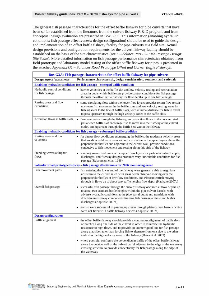
The general fish passage characteristics for the offset baffle fishway for pipe culverts that have been so far established from the literature, from the culvert fishway R & D program, and from conceptual design evaluation are presented in Box G3.5. This information (enabling hydraulic conditions; fish passage effectiveness; design configuration) should be used to guide the design and implementation of an offset baffle fishway facility for pipe culverts at a field site. Actual design provisions and configuration requirements for the culvert fishway facility should be established on the basis of the site characteristics (see Guidelines Part E – Fish Passage Design: Site Scale). More detailed information on fish passage performance characteristics obtained from field prototype and laboratory model testing of the offset baffle fishway for pipes is presented in the attached Appendix G1 – Solander Road Prototype Offset and Corner Baffle Fishways.
Box G3.5: Fish passage characteristics for offset baffle fishway for pipe culverts Design aspect / parameter Performance characteristic, design consideration, comment and rationale
Enabling hydraulic conditions for fish passage – emerged baffle condition
Hydraulic control conditions for fish passage
barrier velocities at the baffle slot and low velocity resting and recirculation areas in pools within baffle sets provide control conditions for fish passage through the offset baffle fishway for flow depths up to one baffle height
Resting areas and flow circulation
some circulating flow within the lower flow layers provides return flow to suit upstream fish movement in the baffle zone and low velocity resting areas for fish adjacent to the line of baffle slots, with minimal distance for fish to travel to pass upstream through the high velocity zones at the baffle slots
Attraction flows at baffle slots flow continuity through the fishway, and attraction flows in the concentrated jets at each baffle slot encourage fish to move into the fishway at the culvert outlet, and upstream through the baffle sets within the fishway
Enabling hydraulic conditions for fish passage – submerged baffle condition
Resting areas and low velocities
for deeper flow conditions submerging the baffles, the moderate velocity areas that are directed downstream without circulation in the upper layers above the perpendicular baffles and adjacent to the culvert wall, provide conditions conducive to fish movement and resting along this side of the fishway
Standing waves at higher flows
standing wave conditions in the upper flow layers for particular culvert slopes, discharges, and fishway designs produced very undesirable conditions for fish passage (Rajaratnam et al. 1988)
Solander Road prototype fishway – fish passage effectiveness for 2006 monitoring event
Fish movement paths fish entering the lower end of the fishway were generally able to negotiate upstream to the culvert inlet, with glass perch observed moving over the perpendicular baffles at low flow conditions, and Plotosid catfish moving through in flows up to about two baffle heights flow depth (Kapitzke 2007c)
Overall fish passage successful fish passage through the culvert fishway occurred at flow depths up to about two standard baffle heights within the pipe culvert barrels, with adverse hydraulic conditions at the pipe barrel outlet and transitions with downstream fishway components limiting fish passage at these and higher discharges (Kapitzke 2007c)
no fish were successful in passing upstream through plain culvert barrels, which were not fitted with baffle fishway devices (Kapitzke 2007c)
Design configuration
Baffle alignment the offset baffle fishway should provide a continuous alignment of baffle slots or notches along one side of the culvert in order to minimise the hydraulic resistance to high flows, and to provide an uninterrupted line for fish passage along that side rather than forcing fish to alternate from one side to the other and cross the high velocity zone of the fishway (Bates et al. 2003)
where possible, configure the perpendicular baffle of the offset baffle fishway along the outside wall of the culvert barrel adjacent to the edge of the waterway crossing structure to provide connectivitiy for fish passage along the edge of the waterway
VER2.0 -/04/10
School of Engineering and Physical Sciences • Ross Kapitzke • fishways\G_baffle fishways for pipe culverts -/4/10 G-12
Culvert fishway guidelines: Part G – Baffle fishways for pipe culverts
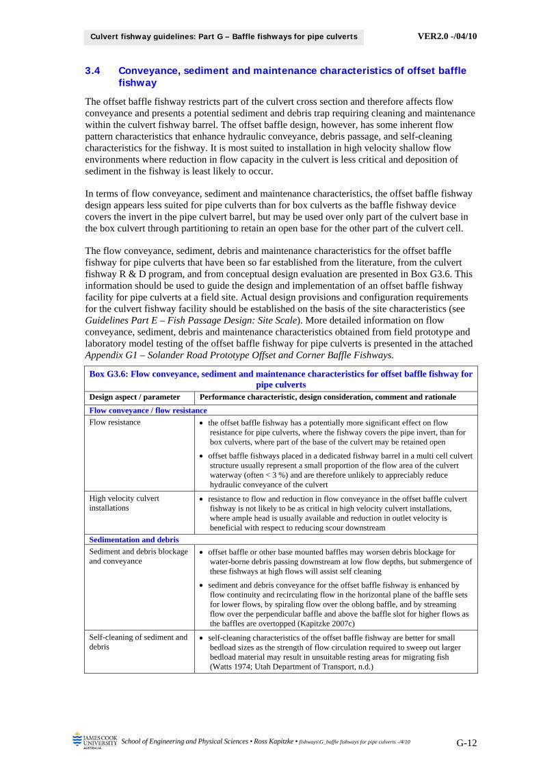
3.4 Conveyance, sediment and maintenance characteristics of offset baffle fishway
The offset baffle fishway restricts part of the culvert cross section and therefore affects flow conveyance and presents a potential sediment and debris trap requiring cleaning and maintenance within the culvert fishway barrel. The offset baffle design, however, has some inherent flow pattern characteristics that enhance hydraulic conveyance, debris passage, and self-cleaning characteristics for the fishway. It is most suited to installation in high velocity shallow flow environments where reduction in flow capacity in the culvert is less critical and deposition of sediment in the fishway is least likely to occur.
In terms of flow conveyance, sediment and maintenance characteristics, the offset baffle fishway design appears less suited for pipe culverts than for box culverts as the baffle fishway device covers the invert in the pipe culvert barrel, but may be used over only part of the culvert base in the box culvert through partitioning to retain an open base for the other part of the culvert cell.
The flow conveyance, sediment, debris and maintenance characteristics for the offset baffle fishway for pipe culverts that have been so far established from the literature, from the culvert fishway R & D program, and from conceptual design evaluation are presented in Box G3.6. This information should be used to guide the design and implementation of an offset baffle fishway facility for pipe culverts at a field site. Actual design provisions and configuration requirements for the culvert fishway facility should be established on the basis of the site characteristics (see Guidelines Part E – Fish Passage Design: Site Scale). More detailed information on flow conveyance, sediment, debris and maintenance characteristics obtained from field prototype and laboratory model testing of the offset baffle fishway for pipe culverts is presented in the attached Appendix G1 – Solander Road Prototype Offset and Corner Baffle Fishways.
Box G3.6: Flow conveyance, sediment and maintenance characteristics for offset baffle fishway for pipe culverts
Design aspect / parameter Performance characteristic, design consideration, comment and rationale
Flow conveyance / flow resistance
Flow resistance the offset baffle fishway has a potentially more significant effect on flow resistance for pipe culverts, where the fishway covers the pipe invert, than for box culverts, where part of the base of the culvert may be retained open
offset baffle fishways placed in a dedicated fishway barrel in a multi cell culvert structure usually represent a small proportion of the flow area of the culvert waterway (often < 3 %) and are therefore unlikely to appreciably reduce hydraulic conveyance of the culvert
High velocity culvert installations
resistance to flow and reduction in flow conveyance in the offset baffle culvert fishway is not likely to be as critical in high velocity culvert installations, where ample head is usually available and reduction in outlet velocity is beneficial with respect to reducing scour downstream
Sedimentation and debris
Sediment and debris blockage and conveyance
offset baffle or other base mounted baffles may worsen debris blockage for water-borne debris passing downstream at low flow depths, but submergence of these fishways at high flows will assist self cleaning
sediment and debris conveyance for the offset baffle fishway is enhanced by flow continuity and recirculating flow in the horizontal plane of the baffle sets for lower flows, by spiraling flow over the oblong baffle, and by streaming flow over the perpendicular baffle and above the baffle slot for higher flows as the baffles are overtopped (Kapitzke 2007c)
Self-cleaning of sediment and debris
self-cleaning characteristics of the offset baffle fishway are better for small bedload sizes as the strength of flow circulation required to sweep out larger bedload material may result in unsuitable resting areas for migrating fish (Watts 1974; Utah Department of Transport, n.d.)
VER2.0 -/04/10
School of Engineering and Physical Sciences • Ross Kapitzke • fishways\G_baffle fishways for pipe culverts -/4/10 G-13
Culvert fishway guidelines: Part G – Baffle fishways for pipe culverts
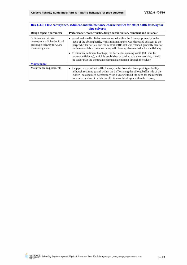
Box G3.6: Flow conveyance, sediment and maintenance characteristics for offset baffle fishway for pipe culverts
Design aspect / parameter Performance characteristic, design consideration, comment and rationale
Sediment and debris conveyance – Solander Road prototype fishway for 2006 monitoring event
gravel and small cobbles were deposited within the fishway, primarily in the apex of the oblong baffle, whilst minimal gravel was deposited adjacent to the perpendicular baffles, and the central baffle slot was retained generally clear of sediment or debris, demonstrating self cleaning characteristics for the fishway
to minimise sediment blockage, the baffle slot opening width (100 mm for prototype fishway), which is established according to the culvert size, should be wider than the dominant sediment size passing through the culvert
Maintenance
Maintenance requirements the pipe culvert offset baffle fishway in the Solander Road prototype facility, although retaining gravel within the baffles along the oblong baffle side of the culvert, has operated successfully for 2 years without the need for maintenance to remove sediment or debris collections or blockages within the fishway
VER2.0 -/04/10
School of Engineering and Physical Sciences • Ross Kapitzke • fishways\G_baffle fishways for pipe culverts -/4/10 G-14
Culvert fishway guidelines: Part G – Baffle fishways for pipe culverts
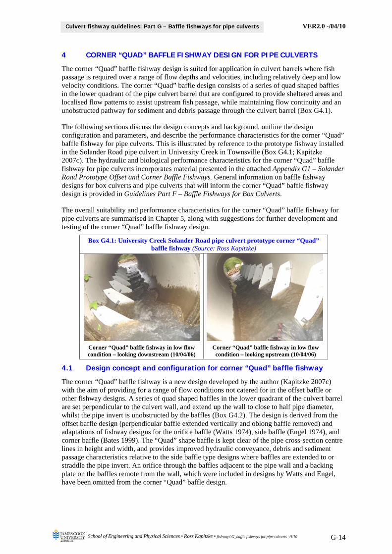
4 CORNER “QUAD” BAFFLE FISHWAY DESIGN FOR PIPE CULVERTS
The corner “Quad” baffle fishway design is suited for application in culvert barrels where fish passage is required over a range of flow depths and velocities, including relatively deep and low velocity conditions. The corner “Quad” baffle design consists of a series of quad shaped baffles in the lower quadrant of the pipe culvert barrel that are configured to provide sheltered areas and localised flow patterns to assist upstream fish passage, while maintaining flow continuity and an unobstructed pathway for sediment and debris passage through the culvert barrel (Box G4.1).
The following sections discuss the design concepts and background, outline the design configuration and parameters, and describe the performance characteristics for the corner “Quad” baffle fishway for pipe culverts. This is illustrated by reference to the prototype fishway installed in the Solander Road pipe culvert in University Creek in Townsville (Box G4.1; Kapitzke 2007c). The hydraulic and biological performance characteristics for the corner “Quad” baffle fishway for pipe culverts incorporates material presented in the attached Appendix G1 – Solander Road Prototype Offset and Corner Baffle Fishways. General information on baffle fishway designs for box culverts and pipe culverts that will inform the corner “Quad” baffle fishway design is provided in Guidelines Part F – Baffle Fishways for Box Culverts.
The overall suitability and performance characteristics for the corner “Quad” baffle fishway for pipe culverts are summarised in Chapter 5, along with suggestions for further development and testing of the corner “Quad” baffle fishway design.
Box G4.1: University Creek Solander Road pipe culvert prototype corner “Quad” baffle fishway (Source: Ross Kapitzke)
Corner “Quad” baffle fishway in low flow condition – looking downstream (10/04/06)
Corner “Quad” baffle fishway in low flow condition – looking upstream (10/04/06)
4.1 Design concept and configuration for corner “Quad” baffle fishway
The corner “Quad” baffle fishway is a new design developed by the author (Kapitzke 2007c) with the aim of providing for a range of flow conditions not catered for in the offset baffle or other fishway designs. A series of quad shaped baffles in the lower quadrant of the culvert barrel are set perpendicular to the culvert wall, and extend up the wall to close to half pipe diameter, whilst the pipe invert is unobstructed by the baffles (Box G4.2). The design is derived from the offset baffle design (perpendicular baffle extended vertically and oblong baffle removed) and adaptations of fishway designs for the orifice baffle (Watts 1974), side baffle (Engel 1974), and corner baffle (Bates 1999). The “Quad” shape baffle is kept clear of the pipe cross-section centre lines in height and width, and provides improved hydraulic conveyance, debris and sediment passage characteristics relative to the side baffle type designs where baffles are extended to or straddle the pipe invert. An orifice through the baffles adjacent to the pipe wall and a backing plate on the baffles remote from the wall, which were included in designs by Watts and Engel, have been omitted from the corner “Quad” baffle design.
VER2.0 -/04/10
School of Engineering and Physical Sciences • Ross Kapitzke • fishways\G_baffle fishways for pipe culverts -/4/10 G-15
Culvert fishway guidelines: Part G – Baffle fishways for pipe culverts
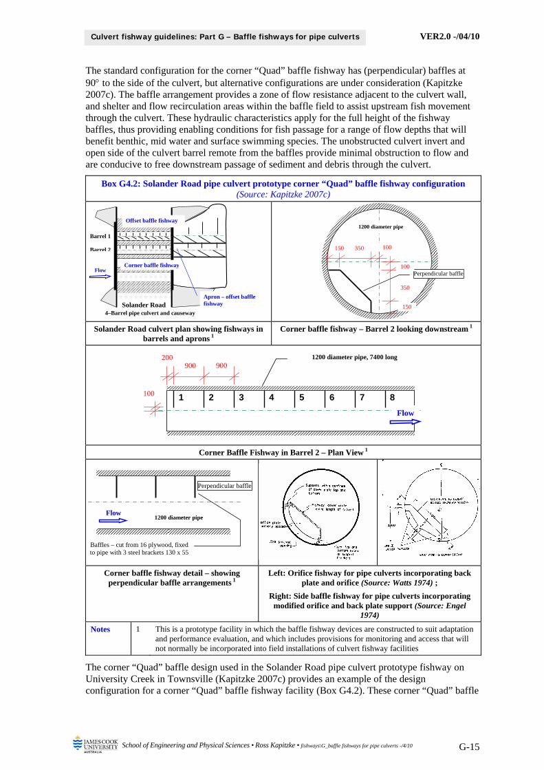
The standard configuration for the corner “Quad” baffle fishway has (perpendicular) baffles at 90 to the side of the culvert, but alternative configurations are under consideration (Kapitzke 2007c). The baffle arrangement provides a zone of flow resistance adjacent to the culvert wall, and shelter and flow recirculation areas within the baffle field to assist upstream fish movement through the culvert. These hydraulic characteristics apply for the full height of the fishway baffles, thus providing enabling conditions for fish passage for a range of flow depths that will benefit benthic, mid water and surface swimming species. The unobstructed culvert invert and open side of the culvert barrel remote from the baffles provide minimal obstruction to flow and are conducive to free downstream passage of sediment and debris through the culvert.
Box G4.2: Solander Road pipe culvert prototype corner “Quad” baffle fishway configuration (Source: Kapitzke 2007c)
Solander Road culvert plan showing fishways in barrels and aprons 1
Corner baffle fishway – Barrel 2 looking downstream 1
Corner Baffle Fishway in Barrel 2 – Plan View 1
Corner baffle fishway detail – showing perpendicular baffle arrangements 1
Left: Orifice fishway for pipe culverts incorporating back plate and orifice (Source: Watts 1974) ;
Right: Side baffle fishway for pipe culverts incorporating modified orifice and back plate support (Source: Engel
1974)
Notes 1 This is a prototype facility in which the baffle fishway devices are constructed to suit adaptation and performance evaluation, and which includes provisions for monitoring and access that will not normally be incorporated into field installations of culvert fishway facilities
The corner “Quad” baffle design used in the Solander Road pipe culvert prototype fishway on University Creek in Townsville (Kapitzke 2007c) provides an example of the design configuration for a corner “Quad” baffle fishway facility (Box G4.2). These corner “Quad” baffle
Solander Road4–Barrel pipe culvert and causeway
Corner baffle fishway
Offset baffle fishway
Apron – offset baffle fishway
Barrel 1
Barrel 2
Flow
1 2 3 4 5 6 7 8
900 200
Flow
100
900 1200 diameter pipe, 7400 long
Perpendicular baffle
150
100 350 150
1200 diameter pipe
100
350
Perpendicular baffle
Baffles – cut from 16 plywood, fixed to pipe with 3 steel brackets 130 x 55
1200 diameter pipe Flow
VER2.0 -/04/10
School of Engineering and Physical Sciences • Ross Kapitzke • fishways\G_baffle fishways for pipe culverts -/4/10 G-16
Culvert fishway guidelines: Part G – Baffle fishways for pipe culverts
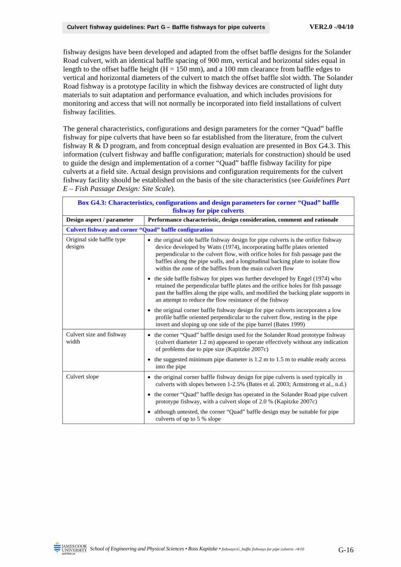
fishway designs have been developed and adapted from the offset baffle designs for the Solander Road culvert, with an identical baffle spacing of 900 mm, vertical and horizontal sides equal in length to the offset baffle height (H = 150 mm), and a 100 mm clearance from baffle edges to vertical and horizontal diameters of the culvert to match the offset baffle slot width. The Solander Road fishway is a prototype facility in which the fishway devices are constructed of light duty materials to suit adaptation and performance evaluation, and which includes provisions for monitoring and access that will not normally be incorporated into field installations of culvert fishway facilities.
The general characteristics, configurations and design parameters for the corner “Quad” baffle fishway for pipe culverts that have been so far established from the literature, from the culvert fishway R & D program, and from conceptual design evaluation are presented in Box G4.3. This information (culvert fishway and baffle configuration; materials for construction) should be used to guide the design and implementation of a corner “Quad” baffle fishway facility for pipe culverts at a field site. Actual design provisions and configuration requirements for the culvert fishway facility should be established on the basis of the site characteristics (see Guidelines Part E – Fish Passage Design: Site Scale).
Box G4.3: Characteristics, configurations and design parameters for corner “Quad” baffle fishway for pipe culverts
Design aspect / parameter Performance characteristic, design consideration, comment and rationale
Culvert fishway and corner “Quad” baffle configuration
Original side baffle type designs
the original side baffle fishway design for pipe culverts is the orifice fishway device developed by Watts (1974), incorporating baffle plates oriented perpendicular to the culvert flow, with orifice holes for fish passage past the baffles along the pipe walls, and a longitudinal backing plate to isolate flow within the zone of the baffles from the main culvert flow
the side baffle fishway for pipes was further developed by Engel (1974) who retained the perpendicular baffle plates and the orifice holes for fish passage past the baffles along the pipe walls, and modified the backing plate supports in an attempt to reduce the flow resistance of the fishway
the original corner baffle fishway design for pipe culverts incorporates a low profile baffle oriented perpendicular to the culvert flow, resting in the pipe invert and sloping up one side of the pipe barrel (Bates 1999)
Culvert size and fishway width
the corner “Quad” baffle design used for the Solander Road prototype fishway (culvert diameter 1.2 m) appeared to operate effectively without any indication of problems due to pipe size (Kapitzke 2007c)
the suggested minimum pipe diameter is 1.2 m to 1.5 m to enable ready access into the pipe
Culvert slope the original corner baffle fishway design for pipe culverts is used typically in culverts with slopes between 1-2.5% (Bates et al. 2003; Armstrong et al., n.d.)
the corner “Quad” baffle design has operated in the Solander Road pipe culvert prototype fishway, with a culvert slope of 2.0 % (Kapitzke 2007c)
although untested, the corner “Quad” baffle design may be suitable for pipe culverts of up to 5 % slope
VER2.0 -/04/10
School of Engineering and Physical Sciences • Ross Kapitzke • fishways\G_baffle fishways for pipe culverts -/4/10 G-17
Culvert fishway guidelines: Part G – Baffle fishways for pipe culverts
Box G4.3: Characteristics, configurations and design parameters for corner “Quad” baffle fishway for pipe culverts
Design aspect / parameter Performance characteristic, design consideration, comment and rationale
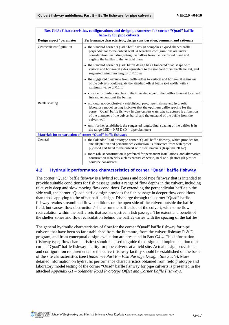
Geometric configuration the standard corner “Quad ” baffle design comprises a quad shaped baffle perpendicular to the culvert wall. Alternative configurations are under consideration, including tilting the baffles from the horizontal plane and angling the baffles to the vertical plane
the standard corner “Quad” baffle design has a truncated quad shape with vertical and horizontal sides equivalent to the standard offset baffle height, and suggested minimum lengths of 0.15 m
the suggested clearance from baffle edges to vertical and horizontal diameters of the culvert should equate the standard offset baffle slot width, with a minimum value of 0.1 m
consider providing notches in the truncated edge of the baffles to assist localised fish movement past the baffles
Baffle spacing although not conclusively established, prototype fishway and hydraulic laboratory model testing indicates that the optimum baffle spacing for the corner “Quad” baffle fishway in pipe culvert waterway structures is a function of the diameter of the culvert barrel and the outstand of the baffle from the culvert wall
until further established, the suggested longitudinal spacing of the baffles is in the range 0.5D – 0.75 D (D = pipe diameter)
Materials for construction of corner “Quad” baffle fishways
General the Solander Road prototype corner “Quad” baffle fishway, which provides for site adaptation and performance evaluation, is fabricated from waterproof plywood and fixed to the culvert with steel brackets (Kapitzke 2007c)
more robust construction is preferred for permanent installations, and alternative construction materials such as precast concrete, steel or high strength plastics could be considered
4.2 Hydraulic performance characteristics of corner “Quad” baffle fishway
The corner “Quad” baffle fishway is a hybrid roughness and pool type fishway that is intended to provide suitable conditions for fish passage under a range of flow depths in the culvert, including relatively deep and slow moving flow conditions. By extending the perpendicular baffle up the side wall, the corner “Quad” baffle design provides for fish passage in deeper flow conditions than those applying to the offset baffle design. Discharge through the corner “Quad” baffle fishway retains streamlined flow conditions on the open side of the culvert outside the baffle field, but causes flow obstruction / shelter on the baffle side of the culvert, with some flow recirculation within the baffle sets that assists upstream fish passage. The extent and benefit of the shelter zones and flow recirculation behind the baffles varies with the spacing of the baffles.
The general hydraulic characteristics of flow for the corner “Quad” baffle fishway for pipe culverts that have been so far established from the literature, from the culvert fishway R & D program, and from conceptual design evaluation are presented in Box G4.4. This information (fishway type; flow characteristics) should be used to guide the design and implementation of a corner “Quad” baffle fishway facility for pipe culverts at a field site. Actual design provisions and configuration requirements for the culvert fishway facility should be established on the basis of the site characteristics (see Guidelines Part E – Fish Passage Design: Site Scale). More detailed information on hydraulic performance characteristics obtained from field prototype and laboratory model testing of the corner “Quad” baffle fishway for pipe culverts is presented in the attached Appendix G1 – Solander Road Prototype Offset and Corner Baffle Fishways.
VER2.0 -/04/10
School of Engineering and Physical Sciences • Ross Kapitzke • fishways\G_baffle fishways for pipe culverts -/4/10 G-18
Culvert fishway guidelines: Part G – Baffle fishways for pipe culverts
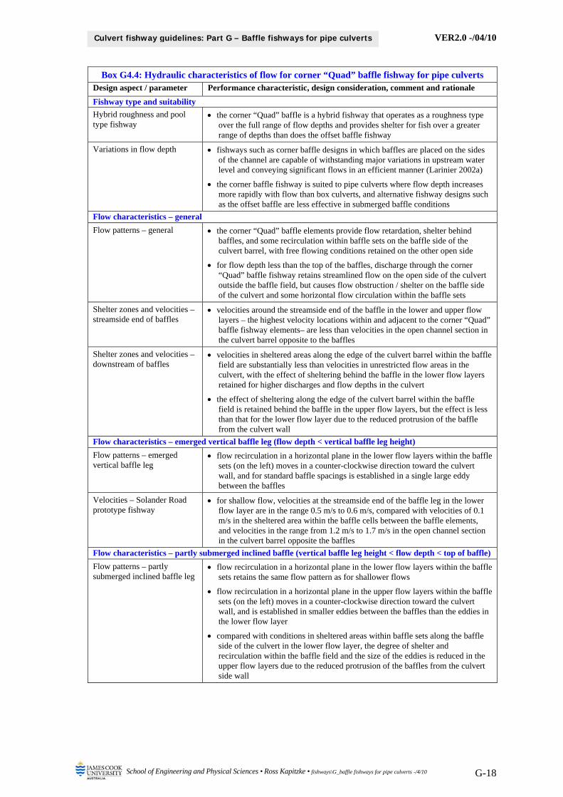
Box G4.4: Hydraulic characteristics of flow for corner “Quad” baffle fishway for pipe culverts Design aspect / parameter Performance characteristic, design consideration, comment and rationale
Fishway type and suitability
Hybrid roughness and pool type fishway
the corner “Quad” baffle is a hybrid fishway that operates as a roughness type over the full range of flow depths and provides shelter for fish over a greater range of depths than does the offset baffle fishway
Variations in flow depth fishways such as corner baffle designs in which baffles are placed on the sides of the channel are capable of withstanding major variations in upstream water level and conveying significant flows in an efficient manner (Larinier 2002a)
the corner baffle fishway is suited to pipe culverts where flow depth increases more rapidly with flow than box culverts, and alternative fishway designs such as the offset baffle are less effective in submerged baffle conditions
Flow characteristics – general
Flow patterns – general the corner “Quad” baffle elements provide flow retardation, shelter behind baffles, and some recirculation within baffle sets on the baffle side of the culvert barrel, with free flowing conditions retained on the other open side
for flow depth less than the top of the baffles, discharge through the corner “Quad” baffle fishway retains streamlined flow on the open side of the culvert outside the baffle field, but causes flow obstruction / shelter on the baffle side of the culvert and some horizontal flow circulation within the baffle sets
Shelter zones and velocities – streamside end of baffles
velocities around the streamside end of the baffle in the lower and upper flow layers – the highest velocity locations within and adjacent to the corner “Quad” baffle fishway elements– are less than velocities in the open channel section in the culvert barrel opposite to the baffles
Shelter zones and velocities – downstream of baffles
velocities in sheltered areas along the edge of the culvert barrel within the baffle field are substantially less than velocities in unrestricted flow areas in the culvert, with the effect of sheltering behind the baffle in the lower flow layers retained for higher discharges and flow depths in the culvert
the effect of sheltering along the edge of the culvert barrel within the baffle field is retained behind the baffle in the upper flow layers, but the effect is less than that for the lower flow layer due to the reduced protrusion of the baffle from the culvert wall
Flow characteristics – emerged vertical baffle leg (flow depth < vertical baffle leg height)
Flow patterns – emerged vertical baffle leg
flow recirculation in a horizontal plane in the lower flow layers within the baffle sets (on the left) moves in a counter-clockwise direction toward the culvert wall, and for standard baffle spacings is established in a single large eddy between the baffles
Velocities – Solander Road prototype fishway
for shallow flow, velocities at the streamside end of the baffle leg in the lower flow layer are in the range 0.5 m/s to 0.6 m/s, compared with velocities of 0.1 m/s in the sheltered area within the baffle cells between the baffle elements, and velocities in the range from 1.2 m/s to 1.7 m/s in the open channel section in the culvert barrel opposite the baffles
Flow characteristics – partly submerged inclined baffle (vertical baffle leg height < flow depth < top of baffle)
Flow patterns – partly submerged inclined baffle leg
flow recirculation in a horizontal plane in the lower flow layers within the baffle sets retains the same flow pattern as for shallower flows
flow recirculation in a horizontal plane in the upper flow layers within the baffle sets (on the left) moves in a counter-clockwise direction toward the culvert wall, and is established in smaller eddies between the baffles than the eddies in the lower flow layer
compared with conditions in sheltered areas within baffle sets along the baffle side of the culvert in the lower flow layer, the degree of shelter and recirculation within the baffle field and the size of the eddies is reduced in the upper flow layers due to the reduced protrusion of the baffles from the culvert side wall
VER2.0 -/04/10
School of Engineering and Physical Sciences • Ross Kapitzke • fishways\G_baffle fishways for pipe culverts -/4/10 G-19
Culvert fishway guidelines: Part G – Baffle fishways for pipe culverts
Box G4.4: Hydraulic characteristics of flow for corner “Quad” baffle fishway for pipe culverts Design aspect / parameter Performance characteristic, design consideration, comment and rationale
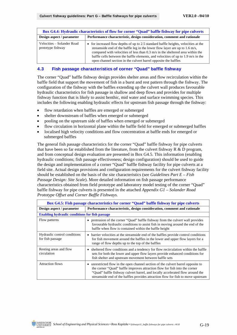
Velocities – Solander Road prototype fishway
for increased flow depths of up to 2.5 standard baffle heights, velocities at the streamside end of the baffle leg in the lower flow layer are up to 1.6 m/s, compared with velocities of less than 0.3 m/s in the sheltered area within the baffle cells between the baffle elements, and velocities of up to 1.9 m/s in the open channel section in the culvert barrel opposite the baffles
4.3 Fish passage characteristics of corner “Quad” baffle fishway
The corner “Quad” baffle fishway design provides shelter areas and flow recirculation within the baffle field that support the movement of fish in a burst and rest pattern through the fishway. The configuration of the fishway with the baffles extending up the culvert wall produces favourable hydraulic characteristics for fish passage in shallow and deep flows and provides for multiple fishway function that is likely to assist benthic, mid water and surface swimming species. This includes the following enabling hydraulic effects for upstream fish passage through the fishway:
flow retardation when baffles are emerged or submerged shelter downstream of baffles when emerged or submerged pooling on the upstream side of baffles when emerged or submerged flow circulation in horizontal plane within the baffle field for emerged or submerged baffles localised high velocity conditions and flow concentration at baffle ends for emerged or
submerged baffles
The general fish passage characteristics for the corner “Quad” baffle fishway for pipe culverts that have been so far established from the literature, from the culvert fishway R & D program, and from conceptual design evaluation are presented in Box G4.5. This information (enabling hydraulic conditions; fish passage effectiveness; design configuration) should be used to guide the design and implementation of a corner “Quad” baffle fishway facility for pipe culverts at a field site. Actual design provisions and configuration requirements for the culvert fishway facility should be established on the basis of the site characteristics (see Guidelines Part E – Fish Passage Design: Site Scale). More detailed information on fish passage performance characteristics obtained from field prototype and laboratory model testing of the corner “Quad” baffle fishway for pipe culverts is presented in the attached Appendix G1 – Solander Road Prototype Offset and Corner Baffle Fishways.
Box G4.5: Fish passage characteristics for corner “Quad” baffle fishway for pipe culverts Design aspect / parameter Performance characteristic, design consideration, comment and rationale
Enabling hydraulic conditions for fish passage
Flow patterns protrusion of the corner “Quad” baffle fishway from the culvert wall provides favourable hydraulic conditions to assist fish in moving around the end of the baffle when flow is contained within the baffle height
Hydraulic control conditions for fish passage
barrier velocities at the streamside end of the baffles provide control conditions for fish movement around the baffles in the lower and upper flow layers for a range of flow depths up to the top of the baffles
Resting areas and flow circulation
sheltered flow conditions and a tendency for flow recirculation within the baffle sets for both the lower and upper flow layers provide enhanced conditions for fish shelter and upstream movement between baffle sets
Attraction flows unrestricted flow in the open channel section of the culvert barrel opposite to the corner “Quad” baffle improves attraction flow for fish into the corner “Quad” baffle fishway culvert barrel, and locally accelerated flow around the streamside end of the baffles provides attraction flow for fish to move upstream
VER2.0 -/04/10
School of Engineering and Physical Sciences • Ross Kapitzke • fishways\G_baffle fishways for pipe culverts -/4/10 G-20
Culvert fishway guidelines: Part G – Baffle fishways for pipe culverts
Box G4.5: Fish passage characteristics for corner “Quad” baffle fishway for pipe culverts Design aspect / parameter Performance characteristic, design consideration, comment and rationale
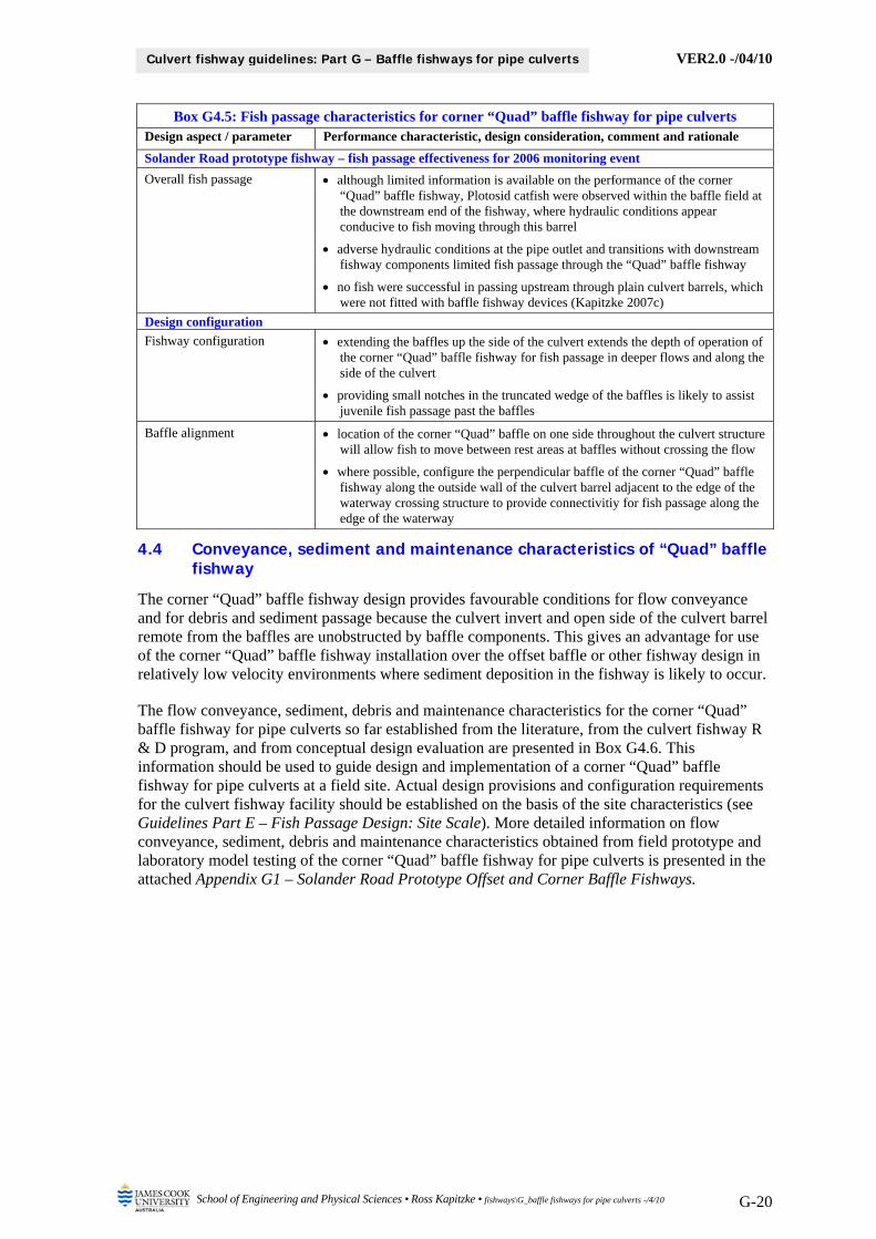
Solander Road prototype fishway – fish passage effectiveness for 2006 monitoring event
Overall fish passage although limited information is available on the performance of the corner “Quad” baffle fishway, Plotosid catfish were observed within the baffle field at the downstream end of the fishway, where hydraulic conditions appear conducive to fish moving through this barrel
adverse hydraulic conditions at the pipe outlet and transitions with downstream fishway components limited fish passage through the “Quad” baffle fishway
no fish were successful in passing upstream through plain culvert barrels, which were not fitted with baffle fishway devices (Kapitzke 2007c)
Design configuration
Fishway configuration extending the baffles up the side of the culvert extends the depth of operation of the corner “Quad” baffle fishway for fish passage in deeper flows and along the side of the culvert
providing small notches in the truncated wedge of the baffles is likely to assist juvenile fish passage past the baffles
Baffle alignment location of the corner “Quad” baffle on one side throughout the culvert structure will allow fish to move between rest areas at baffles without crossing the flow
where possible, configure the perpendicular baffle of the corner “Quad” baffle fishway along the outside wall of the culvert barrel adjacent to the edge of the waterway crossing structure to provide connectivitiy for fish passage along the edge of the waterway
4.4 Conveyance, sediment and maintenance characteristics of “Quad” baffle fishway
The corner “Quad” baffle fishway design provides favourable conditions for flow conveyance and for debris and sediment passage because the culvert invert and open side of the culvert barrel remote from the baffles are unobstructed by baffle components. This gives an advantage for use of the corner “Quad” baffle fishway installation over the offset baffle or other fishway design in relatively low velocity environments where sediment deposition in the fishway is likely to occur.
The flow conveyance, sediment, debris and maintenance characteristics for the corner “Quad” baffle fishway for pipe culverts so far established from the literature, from the culvert fishway R & D program, and from conceptual design evaluation are presented in Box G4.6. This information should be used to guide design and implementation of a corner “Quad” baffle fishway for pipe culverts at a field site. Actual design provisions and configuration requirements for the culvert fishway facility should be established on the basis of the site characteristics (see Guidelines Part E – Fish Passage Design: Site Scale). More detailed information on flow conveyance, sediment, debris and maintenance characteristics obtained from field prototype and laboratory model testing of the corner “Quad” baffle fishway for pipe culverts is presented in the attached Appendix G1 – Solander Road Prototype Offset and Corner Baffle Fishways.
VER2.0 -/04/10
School of Engineering and Physical Sciences • Ross Kapitzke • fishways\G_baffle fishways for pipe culverts -/4/10 G-21
Culvert fishway guidelines: Part G – Baffle fishways for pipe culverts
Box G4.6: Flow conveyance, sediment and maintenance characteristics for corner “Quad” baffle fishway for pipe culverts
Design aspect / parameter Performance characteristic, design consideration, comment and rationale
Flow conveyance / flow resistance
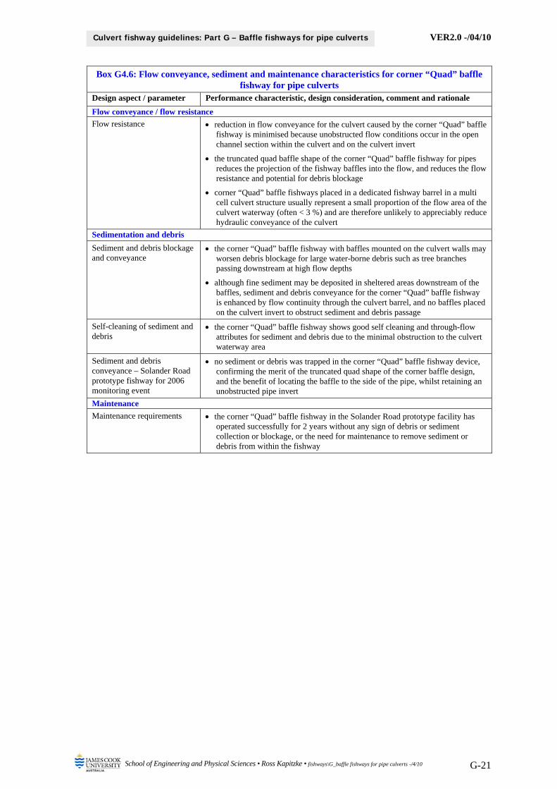
Flow resistance reduction in flow conveyance for the culvert caused by the corner “Quad” baffle fishway is minimised because unobstructed flow conditions occur in the open channel section within the culvert and on the culvert invert
the truncated quad baffle shape of the corner “Quad” baffle fishway for pipes reduces the projection of the fishway baffles into the flow, and reduces the flow resistance and potential for debris blockage
corner “Quad” baffle fishways placed in a dedicated fishway barrel in a multi cell culvert structure usually represent a small proportion of the flow area of the culvert waterway (often < 3 %) and are therefore unlikely to appreciably reduce hydraulic conveyance of the culvert
Sedimentation and debris
Sediment and debris blockage and conveyance
the corner “Quad” baffle fishway with baffles mounted on the culvert walls may worsen debris blockage for large water-borne debris such as tree branches passing downstream at high flow depths
although fine sediment may be deposited in sheltered areas downstream of the baffles, sediment and debris conveyance for the corner “Quad” baffle fishway is enhanced by flow continuity through the culvert barrel, and no baffles placed on the culvert invert to obstruct sediment and debris passage
Self-cleaning of sediment and debris
the corner “Quad” baffle fishway shows good self cleaning and through-flow attributes for sediment and debris due to the minimal obstruction to the culvert waterway area
Sediment and debris conveyance – Solander Road prototype fishway for 2006 monitoring event
no sediment or debris was trapped in the corner “Quad” baffle fishway device, confirming the merit of the truncated quad shape of the corner baffle design, and the benefit of locating the baffle to the side of the pipe, whilst retaining an unobstructed pipe invert
Maintenance
Maintenance requirements the corner “Quad” baffle fishway in the Solander Road prototype facility has operated successfully for 2 years without any sign of debris or sediment collection or blockage, or the need for maintenance to remove sediment or debris from within the fishway
VER2.0 -/04/10
School of Engineering and Physical Sciences • Ross Kapitzke • fishways\G_baffle fishways for pipe culverts -/4/10 G-22
Culvert fishway guidelines: Part G – Baffle fishways for pipe culverts
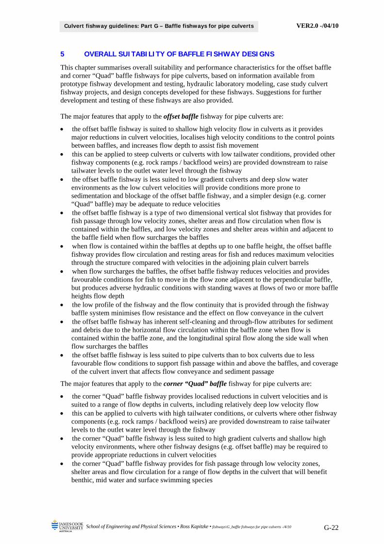
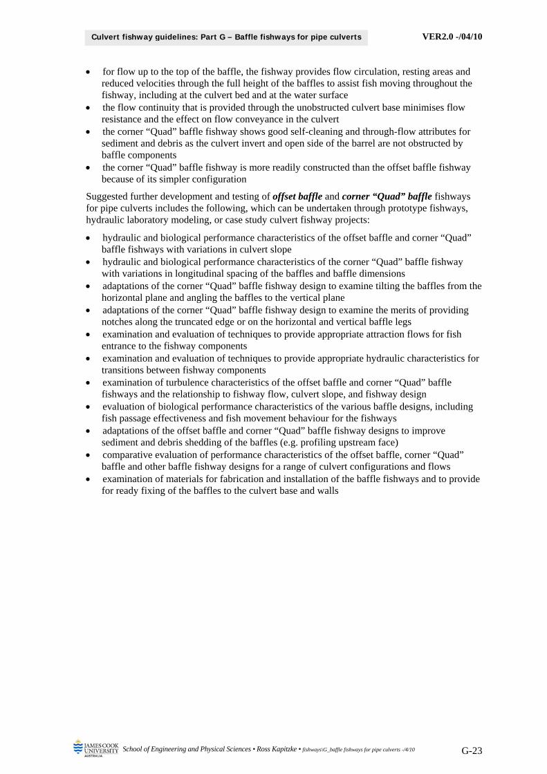
5 OVERALL SUITABILITY OF BAFFLE FISHWAY DESIGNS
This chapter summarises overall suitability and performance characteristics for the offset baffle and corner “Quad” baffle fishways for pipe culverts, based on information available from prototype fishway development and testing, hydraulic laboratory modeling, case study culvert fishway projects, and design concepts developed for these fishways. Suggestions for further development and testing of these fishways are also provided.
The major features that apply to the offset baffle fishway for pipe culverts are:
the offset baffle fishway is suited to shallow high velocity flow in culverts as it provides major reductions in culvert velocities, localises high velocity conditions to the control points between baffles, and increases flow depth to assist fish movement
this can be applied to steep culverts or culverts with low tailwater conditions, provided other fishway components (e.g. rock ramps / backflood weirs) are provided downstream to raise tailwater levels to the outlet water level through the fishway
the offset baffle fishway is less suited to low gradient culverts and deep slow water environments as the low culvert velocities will provide conditions more prone to sedimentation and blockage of the offset baffle fishway, and a simpler design (e.g. corner “Quad” baffle) may be adequate to reduce velocities
the offset baffle fishway is a type of two dimensional vertical slot fishway that provides for fish passage through low velocity zones, shelter areas and flow circulation when flow is contained within the baffles, and low velocity zones and shelter areas within and adjacent to the baffle field when flow surcharges the baffles
when flow is contained within the baffles at depths up to one baffle height, the offset baffle fishway provides flow circulation and resting areas for fish and reduces maximum velocities through the structure compared with velocities in the adjoining plain culvert barrels
when flow surcharges the baffles, the offset baffle fishway reduces velocities and provides favourable conditions for fish to move in the flow zone adjacent to the perpendicular baffle, but produces adverse hydraulic conditions with standing waves at flows of two or more baffle heights flow depth
the low profile of the fishway and the flow continuity that is provided through the fishway baffle system minimises flow resistance and the effect on flow conveyance in the culvert
the offset baffle fishway has inherent self-cleaning and through-flow attributes for sediment and debris due to the horizontal flow circulation within the baffle zone when flow is contained within the baffle zone, and the longitudinal spiral flow along the side wall when flow surcharges the baffles
the offset baffle fishway is less suited to pipe culverts than to box culverts due to less favourable flow conditions to support fish passage within and above the baffles, and coverage of the culvert invert that affects flow conveyance and sediment passage
The major features that apply to the corner “Quad” baffle fishway for pipe culverts are:
the corner “Quad” baffle fishway provides localised reductions in culvert velocities and is suited to a range of flow depths in culverts, including relatively deep low velocity flow
this can be applied to culverts with high tailwater conditions, or culverts where other fishway components (e.g. rock ramps / backflood weirs) are provided downstream to raise tailwater levels to the outlet water level through the fishway
the corner “Quad” baffle fishway is less suited to high gradient culverts and shallow high velocity environments, where other fishway designs (e.g. offset baffle) may be required to provide appropriate reductions in culvert velocities
the corner “Quad” baffle fishway provides for fish passage through low velocity zones, shelter areas and flow circulation for a range of flow depths in the culvert that will benefit benthic, mid water and surface swimming species
VER2.0 -/04/10
School of Engineering and Physical Sciences • Ross Kapitzke • fishways\G_baffle fishways for pipe culverts -/4/10 G-23
Culvert fishway guidelines: Part G – Baffle fishways for pipe culverts
for flow up to the top of the baffle, the fishway provides flow circulation, resting areas and reduced velocities through the full height of the baffles to assist fish moving throughout the fishway, including at the culvert bed and at the water surface
the flow continuity that is provided through the unobstructed culvert base minimises flow resistance and the effect on flow conveyance in the culvert
the corner “Quad” baffle fishway shows good self-cleaning and through-flow attributes for sediment and debris as the culvert invert and open side of the barrel are not obstructed by baffle components
the corner “Quad” baffle fishway is more readily constructed than the offset baffle fishway because of its simpler configuration
Suggested further development and testing of offset baffle and corner “Quad” baffle fishways for pipe culverts includes the following, which can be undertaken through prototype fishways, hydraulic laboratory modeling, or case study culvert fishway projects:
hydraulic and biological performance characteristics of the offset baffle and corner “Quad” baffle fishways with variations in culvert slope
hydraulic and biological performance characteristics of the corner “Quad” baffle fishway with variations in longitudinal spacing of the baffles and baffle dimensions
adaptations of the corner “Quad” baffle fishway design to examine tilting the baffles from the horizontal plane and angling the baffles to the vertical plane
adaptations of the corner “Quad” baffle fishway design to examine the merits of providing notches along the truncated edge or on the horizontal and vertical baffle legs
examination and evaluation of techniques to provide appropriate attraction flows for fish entrance to the fishway components
examination and evaluation of techniques to provide appropriate hydraulic characteristics for transitions between fishway components
examination of turbulence characteristics of the offset baffle and corner “Quad” baffle fishways and the relationship to fishway flow, culvert slope, and fishway design
evaluation of biological performance characteristics of the various baffle designs, including fish passage effectiveness and fish movement behaviour for the fishways
adaptations of the offset baffle and corner “Quad” baffle fishway designs to improve sediment and debris shedding of the baffles (e.g. profiling upstream face)
comparative evaluation of performance characteristics of the offset baffle, corner “Quad” baffle and other baffle fishway designs for a range of culvert configurations and flows
examination of materials for fabrication and installation of the baffle fishways and to provide for ready fixing of the baffles to the culvert base and walls
VER2.0 -/04/10
School of Engineering and Physical Sciences • Ross Kapitzke • fishways\G_baffle fishways for pipe culverts -/4/10 G-24
Culvert fishway guidelines: Part G – Baffle fishways for pipe culverts
6 BIBLIOGRAPHY Armstrong, G., Aprahamian, M., Fewings, A., Gough, P., Reader, N., and Varallo, P., n.d., Fish passes,
Guidance notes on the legislation, selection and approval of fish passes in England and Wales. Bates, K. 1999, Fish passage at road culverts, Washington Department of Fish and Wildlife, 49 p. Bates, K., Barnard, R., Heiner, B., Klavas, J.P., and Powers, P.D., 2003, Design of road culverts for fish
passage, Washington Department of Fish and Wildlife. Engel, P. 1974, Fish facilities for culverts of the McKenzie Highway, National Water Research Institute,
Burlington Ontario 33p. Kapitzke, I.R. 2006a, Bruce Highway Corduroy Creek to Tully planning study Provisions for fish passage
– Road corridor scale Assessment Task 1A, report to Maunsell Australia and Department of Main Roads. Kapitzke, I.R. 2006b, Discovery Drive offset baffle fishway for box culverts (Prototype Fishway # 1): Case
study project design and prototype monitoring report to April 2005, report to Dept of Main Roads. Kapitzke, I.R. 2006c, Douglas Arterial Project rock ramp fishway for open channels (Prototype Fishway #
2): Case study project design and prototype monitoring report to April 2005, report to Dept Main Roads. Kapitzke, I.R. 2007a, Bruce Highway Corduroy Creek to Tully High School Provisions for fish passage –
Preliminary Design Assessment Tasks 1B and 2, report to Maunsell Australia and Dept of Main Roads. Kapitzke, I.R. 2007b, Discovery Drive corner baffle fishway for box culverts (Prototype Fishway # 4):
Case study project design and prototype monitoring report to April 2006, report to Dept of Main Roads. Kapitzke, I.R. 2007c, Solander Road pipe culvert fishway (Prototype Fishway # 3): Case study project
design and prototype monitoring report to April 2006, report to Department of Main Roads. Larinier, M. 2002a, “Baffle fishways”, Chapter 6 in Vineux, E. and Larinier, M. (Eds), Fishways:
Biological basis, design criteria and monitoring, Supplement No 364 to Bulletin Francais de la Peche et de la Pisciculture, p 83 – 101, United Nations FAO.
Larinier, M. 2002b, “Fish passage through culverts, rock weirs and estuarine obstructions”, Chapter 8 in Vineux, E. and Larinier, M. (Eds), Fishways: Biological basis, design criteria and monitoring, Supplement No 364 to Bulletin Francais de la Peche et de la Pisciculture, p 119 – 134, United Nations FAO.
McKinley, W.R. and R.D. Webb. 1956. "A proposed correction of migratory fish problems at box culverts". Washington Department of Fisheries Fish Research Papers 1(4): 33-45, Olympia, WA.
Rajaratnam, N., Katopodis, C. and Lodewyk, S. 1988, “Hydraulics of offset baffle culvert fishways”, Canadian Journal of Civil Engineering, 15(6): 1043-1051.
Utah Department of Transport, n.d., Manual of instruction – Roadway drainage, surface water environment, available at: www.udot.utah.gov/dl.php/tid=826/save/Chapter%2015.pdf
Watts, F. J. 1974, Design of culvert fishways, Water Resources Research Institute, University of Idaho, Moscow, ID.
Yee, C.S. Roelofs, T.D. 1980, “Planning forest roads to protect salmonid habitat”, Meehan, W.R. ed, Influence of forest and rangeland management on anadromous fish habitat in western north America, General Technical Report PNW-109, US Department of Agriculture Forest Service Pacific Northwest Forest and Range Experiment Station, available at: http://www.fs.fed.us/pnw/pubs/pnw_gtr109.pdf#xml=http://www.fs.fed.us/cgi-bin/texis/searchallsites/search.allsites/xml.txt?query=fish+passage+culvert+baffle&db=allsites&id=41c0cbcb0
Ross Kapitzke James Cook University School of Engineering and Physical Sciences April 2010 – VER2.0
VER2.0 -/04/10
School of Engineering and Physical Sciences • Ross Kapitzke • fishways\G_baffle fishways for pipe culverts -/4/10
Culvert fishway guidelines: Part G – Baffle fishways for pipe culverts
APPENDIX G1 – SOLANDER ROAD PROTOTYPE OFFSET AND CORNER BAFFLE FISHWAYS
VER2.0 -/04/10
School of Engineering and Physical Sciences • Ross Kapitzke • fishways\Appendix G1_solander road pipe culvert baffles -/4/10 G1-i
Culvert fishway guidelines: Appendix G1 – Solander Road pipe baffles
James Cook University School of Engineering and Physical Sciences Culvert Fishway Design Guidelines: Part G – Baffle Fishways for Pipe Culverts Appendix G1 – Solander Road Prototype Offset and Corner Baffle Fishways Contents
1 SOLANDER ROAD BAFFLE FISHWAYS FOR PIPE CULVERTS 1
2 PROTOTYPE PIPE BAFFLE FISHWAYS HYDRAULIC MONITORING 3 2.1 Hydraulic monitoring equipment and methods 3 2.2 Hydraulic monitoring results for 2006 4 2.3 Summary of findings – physical monitoring of prototype baffle fishways 8
3 PROTOTYPE PIPE BAFFLE FISHWAY BIOLOGICAL MONITORING 9 3.1 Biological monitoring equipment and methods 9 3.2 Biological monitoring results for 2006 10 3.3 Summary of findings – biological monitoring of prototype baffle fishways 10
4 HYDRAULIC LABORATORY MODELLING 13 4.1 Hydraulic laboratory modelling equipment and methods 13 4.2 Results from hydraulic laboratory modelling 13 4.3 Summary of findings – hydraulic laboratory modelling of baffle fishways for pipes 16
5 BIBLIOGRAPHY 18
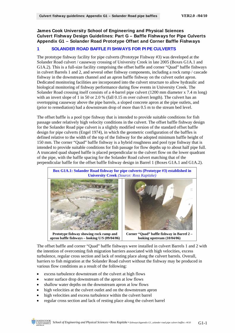
VER2.0 -/04/10
School of Engineering and Physical Sciences • Ross Kapitzke • fishways\Appendix G1_solander road pipe culvert baffles -/4/10 G1-1
Culvert fishway guidelines: Appendix G1 – Solander Road pipe baffles
James Cook University School of Engineering and Physical Sciences Culvert Fishway Design Guidelines: Part G – Baffle Fishways for Pipe Culverts Appendix G1 – Solander Road Prototype Offset and Corner Baffle Fishways
1 SOLANDER ROAD BAFFLE FISHWAYS FOR PIPE CULVERTS
The prototype fishway facility for pipe culverts (Prototype Fishway #3) was developed at the Solander Road culvert / causeway crossing of University Creek in late 2005 (Boxes G1A.1 and G1A.2). This is a full-size facility comprising the offset baffle and corner “Quad” baffle fishways in culvert Barrels 1 and 2, and several other fishway components, including a rock ramp / cascade fishway in the downstream channel and an apron baffle fishway on the culvert outlet apron. Dedicated monitoring facilities are incorporated into the culvert structure to allow hydraulic and biological monitoring of fishway performance during flow events in University Creek. The Solander Road crossing itself consists of a 4-barrel pipe culvert (1200 mm diameter x 7.4 m long) with an invert slope of 1 in 50 or 2.0 % (fall 0.15 m over culvert length). The culvert has an overtopping causeway above the pipe barrels, a sloped concrete apron at the pipe outlets, and (prior to remediation) had a downstream drop of more than 0.5 m to the stream bed level.
The offset baffle is a pool type fishway that is intended to provide suitable conditions for fish passage under relatively high velocity conditions in the culvert. The offset baffle fishway design for the Solander Road pipe culvert is a slightly modified version of the standard offset baffle design for pipe culverts (Engel 1974), in which the geometric configuration of the baffles is defined relative to the width of the top of the fishway for the adopted minimum baffle height of 150 mm. The corner “Quad” baffle fishway is a hybrid roughness and pool type fishway that is intended to provide suitable conditions for fish passage for flow depths up to about half pipe full. A truncated quad shaped baffle is placed perpendicular to the culvert flow on the lower quadrant of the pipe, with the baffle spacing for the Solander Road culvert matching that of the perpendicular baffle for the offset baffle fishway design in Barrel 1 (Boxes G1A.1 and G1A.2).
Box G1A.1: Solander Road fishway for pipe culverts (Prototype #3) established in University Creek (Source: Ross Kapitzke)
Prototype fishway showing rock ramp and apron baffle fishways – looking U/S (09/04/06)
Corner “Quad” baffle fishway in Barrel 2 – looking upstream (10/04/06)
The offset baffle and corner “Quad” baffle fishways were installed in culvert Barrels 1 and 2 with the intention of overcoming fish migration barriers associated with high velocities, excess turbulence, regular cross section and lack of resting place along the culvert barrels. Overall, barriers to fish migration at the Solander Road culvert without the fishway may be produced in various flow conditions as a result of the following:
excess turbulence downstream of the culvert at high flows water surface drop downstream of the apron at low flows shallow water depths on the downstream apron at low flows high velocities at the culvert outlet and on the downstream apron high velocities and excess turbulence within the culvert barrel regular cross section and lack of resting place along the culvert barrel
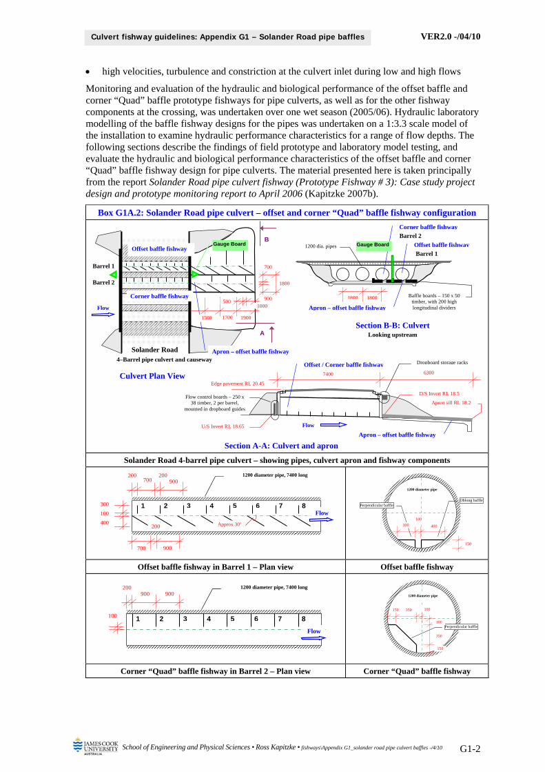
VER2.0 -/04/10
School of Engineering and Physical Sciences • Ross Kapitzke • fishways\Appendix G1_solander road pipe culvert baffles -/4/10 G1-2
Culvert fishway guidelines: Appendix G1 – Solander Road pipe baffles
high velocities, turbulence and constriction at the culvert inlet during low and high flows
Monitoring and evaluation of the hydraulic and biological performance of the offset baffle and corner “Quad” baffle prototype fishways for pipe culverts, as well as for the other fishway components at the crossing, was undertaken over one wet season (2005/06). Hydraulic laboratory modelling of the baffle fishway designs for the pipes was undertaken on a 1:3.3 scale model of the installation to examine hydraulic performance characteristics for a range of flow depths. The following sections describe the findings of field prototype and laboratory model testing, and evaluate the hydraulic and biological performance characteristics of the offset baffle and corner “Quad” baffle fishway design for pipe culverts. The material presented here is taken principally from the report Solander Road pipe culvert fishway (Prototype Fishway # 3): Case study project design and prototype monitoring report to April 2006 (Kapitzke 2007b).
Box G1A.2: Solander Road pipe culvert – offset and corner “Quad” baffle fishway configuration
Solander Road 4-barrel pipe culvert – showing pipes, culvert apron and fishway components
Offset baffle fishway in Barrel 1 – Plan view Offset baffle fishway
Corner “Quad” baffle fishway in Barrel 2 – Plan view Corner “Quad” baffle fishway
Culvert Plan View
Section B-B: Culvert Looking upstream
Section A-A: Culvert and apron
Apron – offset baffle fishway
7400 6300
D/S Invert RL 18.5
Apron sill RL 18.2
Flow
Edge pavement RL 20.45
U/S Invert RL 18.65
Dropboard storage racks
Flow control boards – 250 x 38 timber, 2 per barrel,
mounted in dropboard guides
Offset / Corner baffle fishway
Solander Road 4–Barrel pipe culvert and causeway
Apron – offset baffle fishway
Barrel 1
Barrel 2
B
A
1800
Gauge Board
Corner baffle fishway
Offset baffle fishway
Flow
1700 19001500
1000500
700
900
Offset baffle fishway
Corner baffle fishway
Apron – offset baffle fishway
1200 dia. pipes
Barrel 1
Barrel 2
1800 1800
Gauge Board
Baffle boards – 150 x 50 timber, with 200 high longitudinal dividers
Oblong bafflePerpendicular baffle
150
400
100
300
1200 diameter pipe
1 2 3 4 5 6 7 8
700 200 200
Flow
400
100
300
900
700
200
900
1200 diameter pipe, 7400 long
Approx 30
Perpendicular baffle
150
100 350 150
1200 diameter pipe
100
350
1 2 3 4 5 6 7 8
900 200
Flow
100
900 1200 diameter pipe, 7400 long

VER2.0 -/04/10
School of Engineering and Physical Sciences • Ross Kapitzke • fishways\Appendix G1_solander road pipe culvert baffles -/4/10 G1-3
Culvert fishway guidelines: Appendix G1 – Solander Road pipe baffles
2 PROTOTYPE PIPE BAFFLE FISHWAYS HYDRAULIC MONITORING
An integrated monitoring, modelling and evaluation plan was developed for the fishway in order to evaluate performance in accordance with the design objectives for the facility. This included hydraulic and biological monitoring of the prototype fishway components, hydraulic laboratory modelling of fishway designs, and field studies of University Creek to confirm stream hydrology, culvert hydraulics, fish passage behaviour and the effects of culvert remediation works.
Physical and biological monitoring of the Solander Road prototype fishway examined the hydraulic characteristics of the offset baffle and corner “Quad” baffle fishway devices, their effects on fish migration and behaviour, and the overall effectiveness of these and the other fishway components in the facility. Comparative observations of flow characteristics and fish passage performance were made of the fishway devices, the plain culvert barrels, and adjoining stream sections upstream and downstream of the structure. Field measurements and observations were made during periods of relevant flow to correlate with theoretical data obtained from the desk top studies. This included manipulation of flow and fish barrier conditions through the culvert in order to study hydraulic characteristics and fish behaviour under varying conditions.
The hydraulic monitoring used a flow meter to determine velocity measurements, and direct measurements, observations, photographs and video to examine water depths and flow profiles associated with the fishway and the culvert during periods of relevant flow. The effect of the fishway devices on flow velocities in the culvert was determined, and flow velocity patterns and profiles compiled to allow correlation with the theoretical and laboratory data obtained from desktop studies and hydraulic modelling.
The aims of physical / hydraulic field monitoring of the prototype and in the stream were to:
examine and measure flow depth, velocity, flow pattern and discharge at various locations within the prototype fishway for a range of flow conditions and discharges
examine the potential for sediment / debris obstruction in the fishway and erosion and sedimentation effects in the stream associated with the fishway
integrate hydraulic prototype monitoring with hydraulic field monitoring in adjoining stream reaches, hydraulic laboratory modelling, and associated desktop studies
integrate hydraulic monitoring and evaluation with biological monitoring and other studies contribute to evaluation of the prototype culvert fishway and to determination of design
parameters for other culvert fishway facilities. follow operational and safety procedures for access and monitoring of the prototype facility
2.1 Hydraulic monitoring equipment and methods
Flow observations (flow patterns and fishway performance) at the Solander Road prototype fishway were undertaken for a range of flow conditions, mainly with flow depths less than 0.5 m deep through the fishway. Velocity and flow depth measurements were restricted to periods of shallow flow (typically less than 0.3 m deep) when safe access was available onto the culvert structure and adjoining stream reach. Nib wall flow control boards at the culvert inlet were used to manipulate flow depths through the fishway zones in Barrels 1 and 2, and velocity measurements and observations were obtained within the culvert pipes for the offset baffle fishway, corner “Quad” baffle fishway and the plain culvert barrel, and in other fishway zones.
Observational data were recorded with still and video photography and sketches, and velocity measurements were taken using the Swoffer Instruments Model 3000 data logging flow meter (Box G1A.3). Velocity measurements were taken within lower, mid and upper flow layers in order to record variations in flow conditions with depth in the fishway. Flow depths were measured at each velocity point with a graduated rod, and gauge board readings of water depth were obtained at culvert inlet and outlet headwalls wherever possible. For access and safety reasons, the velocity and depth data could not be obtained throughout the length of the offset and
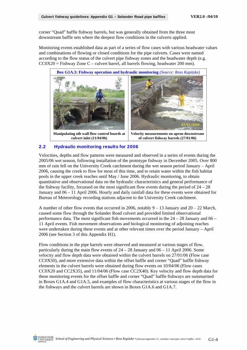
VER2.0 -/04/10
School of Engineering and Physical Sciences • Ross Kapitzke • fishways\Appendix G1_solander road pipe culvert baffles -/4/10 G1-4
Culvert fishway guidelines: Appendix G1 – Solander Road pipe baffles
corner “Quad” baffle fishway barrels, but was generally obtained from the three most downstream baffle sets where the deepest flow conditions in the culverts applied.
Monitoring events established data as part of a series of flow cases with various headwater values and combinations of flowing or closed conditions for the pipe culverts. Cases were named according to the flow status of the culvert pipe fishway zones and the headwater depth (e.g. CC0X20 = Fishway Zone C – culvert barrel, all barrels flowing, headwater 200 mm).
Box G1A.3: Fishway operation and hydraulic monitoring (Source: Ross Kapitzke)
Manipulating nib wall flow control boards at culvert inlet (11/04/06)
Velocity measurements on apron downstream of culvert fishway barrels (27/01/06)
2.2 Hydraulic monitoring results for 2006
Velocities, depths and flow patterns were measured and observed in a series of events during the 2005/06 wet season, following installation of the prototype fishway in December 2005. Over 800 mm of rain fell on the University Creek catchment during the wet season period January – April 2006, causing the creek to flow for most of this time, and to retain water within the fish habitat pools in the upper creek reaches until May / June 2006. Hydraulic monitoring, to obtain quantitative and observational data on the hydraulic characteristics and general performance of the fishway facility, focussed on the most significant flow events during the period of 24 – 28 January and 06 – 11 April 2006. Hourly and daily rainfall data for these events were obtained for Bureau of Meteorology recording stations adjacent to the University Creek catchment.
A number of other flow events that occurred in 2006, notably 9 – 13 January and 20 – 22 March, caused some flow through the Solander Road culvert and provided limited observational performance data. The most significant fish movements occurred in the 24 – 28 January and 06 – 11 April events. Fish movement observations and biological monitoring of adjoining reaches were undertaken during these events and at other relevant times over the period January – April 2006 (see Section 3 of this Appendix H1).
Flow conditions in the pipe barrels were observed and measured at various stages of flow, particularly during the main flow events of 24 – 28 January and 06 – 11 April 2006. Some velocity and flow depth data were obtained within the culvert barrels on 27/01/06 (Flow case CC0X50), and more extensive data within the offset baffle and corner “Quad” baffle fishway elements in the culvert barrels were obtained during flow events on 10/04/06 (Flow cases CC0X20 and CC2X35), and 11/04/06 (Flow case CC2X40). Key velocity and flow depth data for these monitoring events for the offset baffle and corner “Quad” baffle fishways are summarised in Boxes G1A.4 and G1A.5, and examples of flow characteristics at various stages of the flow in the fishways and the culvert barrels are shown in Boxes G1A.6 and G1A.7.

VER2.0 -/04/10
School of Engineering and Physical Sciences • Ross Kapitzke • fishways\Appendix G1_solander road pipe culvert baffles -/4/10 G1-5
Culvert fishway guidelines: Appendix G1 – Solander Road pipe baffles
Box G1A.4: Solander Road prototype fishway velocities and flow depths for 2005/06 field monitoring events – Barrel 1 offset baffle fishway
U/S Baffle Set 1-2 Baffle Set 2-3 Baffle Set D/S
Flow event
Flow case US A B C D E F A B C D E F A B C D E F DS
January 2006 27/01/06
2.30 pm
CC0X50 – all barrels open; HW = 500 mm
Upper flow layer (3)
1.02
360
(Inlet)
0.93
(B3)
1.67
330
(A3)
1.79
(D3)
1.01
390
(A3)
1.28
(E3)
0.64
(F3)
2.08
280
(Outlet)
Baffle Set 6-7 Baffle Set 7-8 Baffle Set D/S
April 2006 10/04/06
12.00 pm
CC0X20 – all barrels open; HW = 200 mm
Lower flow layer
0.57
190
0.04 0.16 0.21 0.51
180
0.49 0.51 0.03
CC2X35 – all barrels open; HW = 350 mm
Upper flow layer (2)
0.81
300
(A2)
0.97
(E2)
0.57
(F2)
0.73
280
(A2)
0.96
(E2)
0.94
(F2)
Lower flow layer (1) 0.76 0.83 0.66 0.43 0.59 0.12 0.40 0.68
11/04/06
6.00 pm
CC2X40 – barrels 3 & 4 blocked; HW = 400 mm
Upper flow layer (3)
0.87
350
(A3)
1.45
(E3)
0.67
(F3)
0.90
360
(A3)
1.49
(E3)
0.57
(F3)
Lower flow layer (1) 0.93 0.66 0.84 0.23 0.84 0.67 0.70 0.64
Legend Upstream & Downstream Baffle Sets – lower flow layer Baffle Sets – upper flow layers Velocities and flow depths
US – mid channel upstream A – Baffle slot E – Over perpendicular baffle – Not applicable: No flow
DS – mid channel downstream B – Oblong baffle side F – Over oblong baffle 1.10 Velocity in m/s
C – Cross flow A2, B2, C2, D2 – layer 2 240 Flow depth in mm
D – Perpendicular baffle side A3, B3, C3, D3 – layer 3 Note - ive velocities opposite direction
F
E
A D
B C
Flow
US DS
D A B
1 2
3
E/D A/C F/B
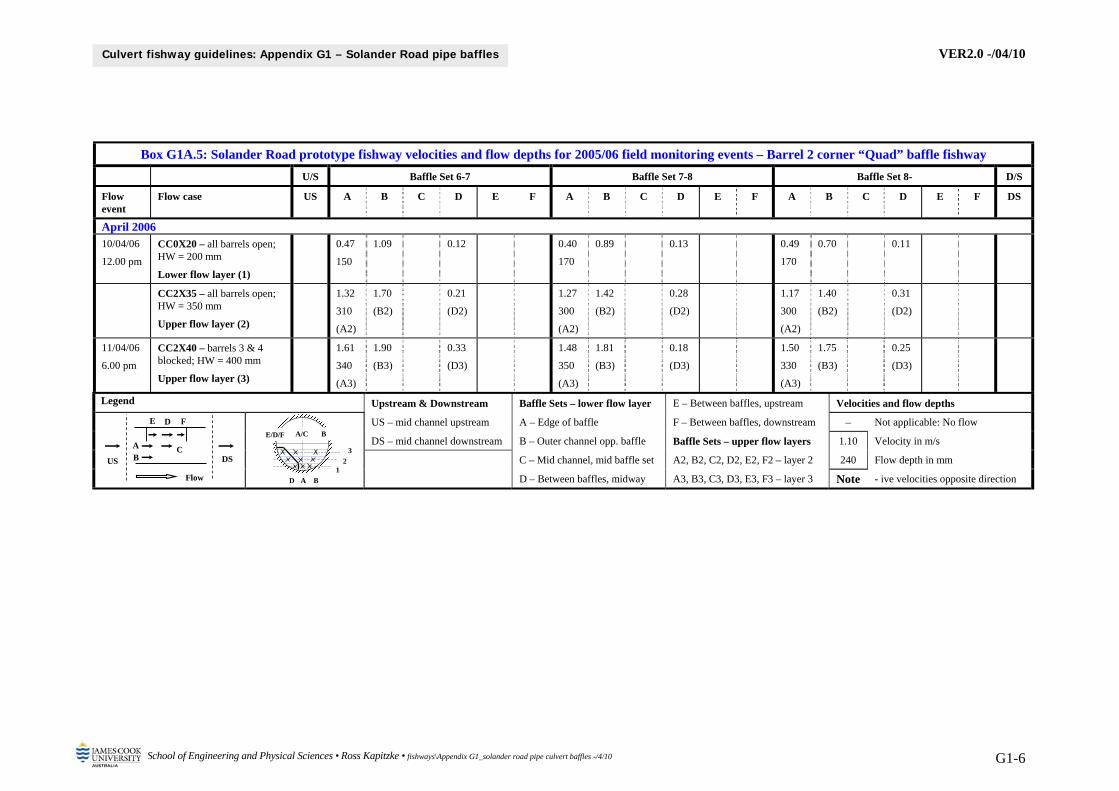
VER2.0 -/04/10
School of Engineering and Physical Sciences • Ross Kapitzke • fishways\Appendix G1_solander road pipe culvert baffles -/4/10 G1-6
Culvert fishway guidelines: Appendix G1 – Solander Road pipe baffles
Box G1A.5: Solander Road prototype fishway velocities and flow depths for 2005/06 field monitoring events – Barrel 2 corner “Quad” baffle fishway
U/S Baffle Set 6-7 Baffle Set 7-8 Baffle Set 8- D/S
Flow event
Flow case US A B C D E F A B C D E F A B C D E F DS
April 2006 10/04/06
12.00 pm
CC0X20 – all barrels open; HW = 200 mm
Lower flow layer (1)
0.47
150
1.09 0.12 0.40
170
0.89 0.13 0.49
170
0.70 0.11
CC2X35 – all barrels open; HW = 350 mm
Upper flow layer (2)
1.32
310
(A2)
1.70
(B2)
0.21
(D2)
1.27
300
(A2)
1.42
(B2)
0.28
(D2)
1.17
300
(A2)
1.40
(B2)
0.31
(D2)
11/04/06
6.00 pm
CC2X40 – barrels 3 & 4 blocked; HW = 400 mm
Upper flow layer (3)
1.61
340
(A3)
1.90
(B3)
0.33
(D3)
1.48
350
(A3)
1.81
(B3)
0.18
(D3)
1.50
330
(A3)
1.75
(B3)
0.25
(D3)
Legend Upstream & Downstream Baffle Sets – lower flow layer E – Between baffles, upstream Velocities and flow depths
US – mid channel upstream A – Edge of baffle F – Between baffles, downstream – Not applicable: No flow
DS – mid channel downstream B – Outer channel opp. baffle Baffle Sets – upper flow layers 1.10 Velocity in m/s
C – Mid channel, mid baffle set A2, B2, C2, D2, E2, F2 – layer 2 240 Flow depth in mm
D – Between baffles, midway A3, B3, C3, D3, E3, F3 – layer 3 Note - ive velocities opposite direction
D A B
1 2
3
E/D/F A/C B
F E
A
D
B C
Flow
US DS

VER2.0 -/04/10
School of Engineering and Physical Sciences • Ross Kapitzke • fishways\Appendix G1_solander road pipe culvert baffles -/4/10 G1-7
Culvert fishway guidelines: Appendix G1 – Solander Road pipe baffles
Box G1A.6: Flow characteristics in offset baffle fishway (Source: Ross Kapitzke)
One standard baffle height flow depth – looking D/S (11/04/06)
One standard baffle height flow depth – looking U/S (11/04/06)
Two and one half standard baffle heights flow depth – looking D/S (11/04/06)
Two and one half standard baffle heights flow depth – looking U/S (11/04/06)
Box G1A.7: Flow characteristics in corner “Quad” baffle fishway (Source: Ross
Kapitzke)
One standard baffle height flow depth – looking D/S (11/04/06)
One standard baffle height flow depth – looking U/S (11/04/06)
Two and one half standard baffle heights flow depth – looking D/S (11/04/06)
Two and one half standard baffle heights flow depth – looking U/S (11/04/06)
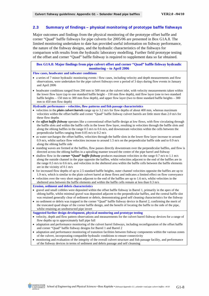
VER2.0 -/04/10
School of Engineering and Physical Sciences • Ross Kapitzke • fishways\Appendix G1_solander road pipe culvert baffles -/4/10 G1-8
Culvert fishway guidelines: Appendix G1 – Solander Road pipe baffles
2.3 Summary of findings – physical monitoring of prototype baffle fishways
Major outcomes and findings from the physical monitoring of the prototype offset baffle and corner “Quad” baffle fishways for pipe culverts for 2005/06 are presented in Box G1A.8. The limited monitoring undertaken to date has provided useful information on fishway performance, the nature of the fishway designs, and the hydraulic characteristics of the fishways for comparison with results from the hydraulic laboratory modelling. Further field prototype testing of the offset and corner “Quad” baffle fishway is required to supplement data so far obtained.
Box G1A.8: Major findings from pipe culvert offset and corner “Quad” baffle fishway hydraulic monitoring – to April 2006
Flow cases, headwater and tailwater conditions
a series of 7 minor hydraulic monitoring events / flow cases, including velocity and depth measurements and flow observations, were undertaken for the pipe culvert fishways over a period of 3 days during flow events in January and April 2006
headwater conditions ranged from 200 mm to 500 mm at the culvert inlet, with velocity measurements taken within the lower flow layer (up to one standard baffle height – 150 mm flow depth), mid flow layer (one to two standard baffle heights – 150 mm to 300 mm flow depth), and upper flow layer (two to three standard baffle heights – 300 mm to 450 mm flow depth)
Hydraulic performance – velocities, flow patterns and fish passage characteristics velocities in the plain culvert barrels range up to 3.2 m/s for flow depths of about 400 mm, whereas maximum
velocities within the offset baffle and corner “Quad” baffle fishway culvert barrels are little more than 2.0 m/s for these flow depths
the offset baffle fishway operates like a conventional offset baffle design at low flows, with flow circulating through the baffle slots and within the baffle cells in the lower flow layer, resulting in velocities through the baffle slots and along the oblong baffles in the range 0.5 m/s to 0.6 m/s, and downstream velocities within the cells between the perpendicular baffles ranging from 0.05 m/s to 0.2 m/s
as water surcharges the offset baffles, velocities through the baffle slots in the lower flow layer increase to around 0.9 m/s, whilst surface flow velocities increase to around 1.5 m/s on the perpendicular baffle side and to 0.9 m/s along the oblong baffle side
standing waves are formed at the baffles, flow passes directly downstream over the perpendicular baffles, and flow is directed across the oblong baffles in a spiralling manner toward the centre of the pipe barrel and fishway
shallow flow in the corner “Quad” baffle fishway produces maximum velocities in the range 0.7 m/s to 1.1 m/s along the outside channel in the pipe opposite the baffles, whilst velocities adjacent to the end of the baffles are in the range 0.5 m/s to 0.6 m/s, and velocities in the sheltered area within the baffle cells between the baffle elements are in the vicinity of 0.1 m/s
for increased flow depths of up to 2.5 standard baffle heights, outer channel velocities opposite the baffles are up to 1.9 m/s, which is similar to the plain culvert barrel at these flows and indicates a limited effect on flow conveyance
velocities over the very short region adjacent to the end of the baffles are up to 1.6 m/s, whilst velocities in the sheltered area between the baffle elements and within the baffle cells remain at less than 0.3 m/s
Erosion, sediment and debris characteristics gravel and small cobbles were deposited within the offset baffle fishway in Barrel 1, primarily in the apex of the
oblong baffle, whilst minimal gravel was deposited adjacent to the perpendicular baffles, and the central baffle slot was retained generally clear of sediment or debris, demonstrating good self cleaning characteristics for the fishway
no sediment or debris was trapped in the corner “Quad” baffle fishway device in Barrel 2, confirming the merit of the truncated quad shape of the corner baffle design, and the benefit of locating the baffle to the side of the pipe, whilst retaining an unobstructed pipe invert
Suggested further design development, physical monitoring and prototype testing velocity, depth and flow pattern observations and measurements for the culvert barrel fishway devices for a range of
flow depths up to approximately half pipe full adaptation and performance monitoring of the culvert barrel fishways, including reconfiguration of the offset baffle
and corner “Quad” baffle fishway designs for Barrel 1 and Barrel 2 adaptation and performance monitoring of transition facilities between fishway components within the various zones
of the culvert, incorporating compatible hydraulic conditions to ensure connectivity monitoring and evaluation of the integrity of the overall culvert structure and fish passage facility, and performance
of the fishway devices in terms of sediment and debris passage and self cleansing
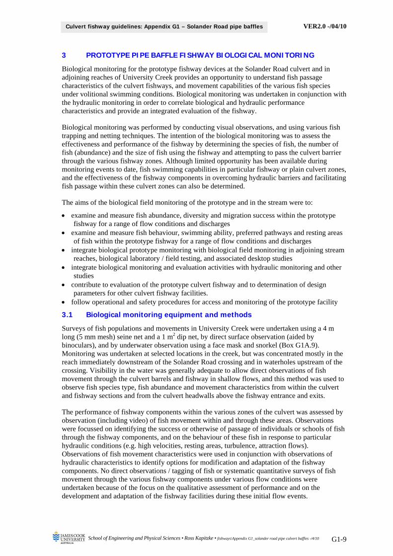
VER2.0 -/04/10
School of Engineering and Physical Sciences • Ross Kapitzke • fishways\Appendix G1_solander road pipe culvert baffles -/4/10 G1-9
Culvert fishway guidelines: Appendix G1 – Solander Road pipe baffles
3 PROTOTYPE PIPE BAFFLE FISHWAY BIOLOGICAL MONITORING
Biological monitoring for the prototype fishway devices at the Solander Road culvert and in adjoining reaches of University Creek provides an opportunity to understand fish passage characteristics of the culvert fishways, and movement capabilities of the various fish species under volitional swimming conditions. Biological monitoring was undertaken in conjunction with the hydraulic monitoring in order to correlate biological and hydraulic performance characteristics and provide an integrated evaluation of the fishway.
Biological monitoring was performed by conducting visual observations, and using various fish trapping and netting techniques. The intention of the biological monitoring was to assess the effectiveness and performance of the fishway by determining the species of fish, the number of fish (abundance) and the size of fish using the fishway and attempting to pass the culvert barrier through the various fishway zones. Although limited opportunity has been available during monitoring events to date, fish swimming capabilities in particular fishway or plain culvert zones, and the effectiveness of the fishway components in overcoming hydraulic barriers and facilitating fish passage within these culvert zones can also be determined.
The aims of the biological field monitoring of the prototype and in the stream were to:
examine and measure fish abundance, diversity and migration success within the prototype fishway for a range of flow conditions and discharges
examine and measure fish behaviour, swimming ability, preferred pathways and resting areas of fish within the prototype fishway for a range of flow conditions and discharges
integrate biological prototype monitoring with biological field monitoring in adjoining stream reaches, biological laboratory / field testing, and associated desktop studies
integrate biological monitoring and evaluation activities with hydraulic monitoring and other studies
contribute to evaluation of the prototype culvert fishway and to determination of design parameters for other culvert fishway facilities.
follow operational and safety procedures for access and monitoring of the prototype facility
3.1 Biological monitoring equipment and methods
Surveys of fish populations and movements in University Creek were undertaken using a 4 m long (5 mm mesh) seine net and a 1 m2 dip net, by direct surface observation (aided by binoculars), and by underwater observation using a face mask and snorkel (Box G1A.9). Monitoring was undertaken at selected locations in the creek, but was concentrated mostly in the reach immediately downstream of the Solander Road crossing and in waterholes upstream of the crossing. Visibility in the water was generally adequate to allow direct observations of fish movement through the culvert barrels and fishway in shallow flows, and this method was used to observe fish species type, fish abundance and movement characteristics from within the culvert and fishway sections and from the culvert headwalls above the fishway entrance and exits.
The performance of fishway components within the various zones of the culvert was assessed by observation (including video) of fish movement within and through these areas. Observations were focussed on identifying the success or otherwise of passage of individuals or schools of fish through the fishway components, and on the behaviour of these fish in response to particular hydraulic conditions (e.g. high velocities, resting areas, turbulence, attraction flows). Observations of fish movement characteristics were used in conjunction with observations of hydraulic characteristics to identify options for modification and adaptation of the fishway components. No direct observations / tagging of fish or systematic quantitative surveys of fish movement through the various fishway components under various flow conditions were undertaken because of the focus on the qualitative assessment of performance and on the development and adaptation of the fishway facilities during these initial flow events.
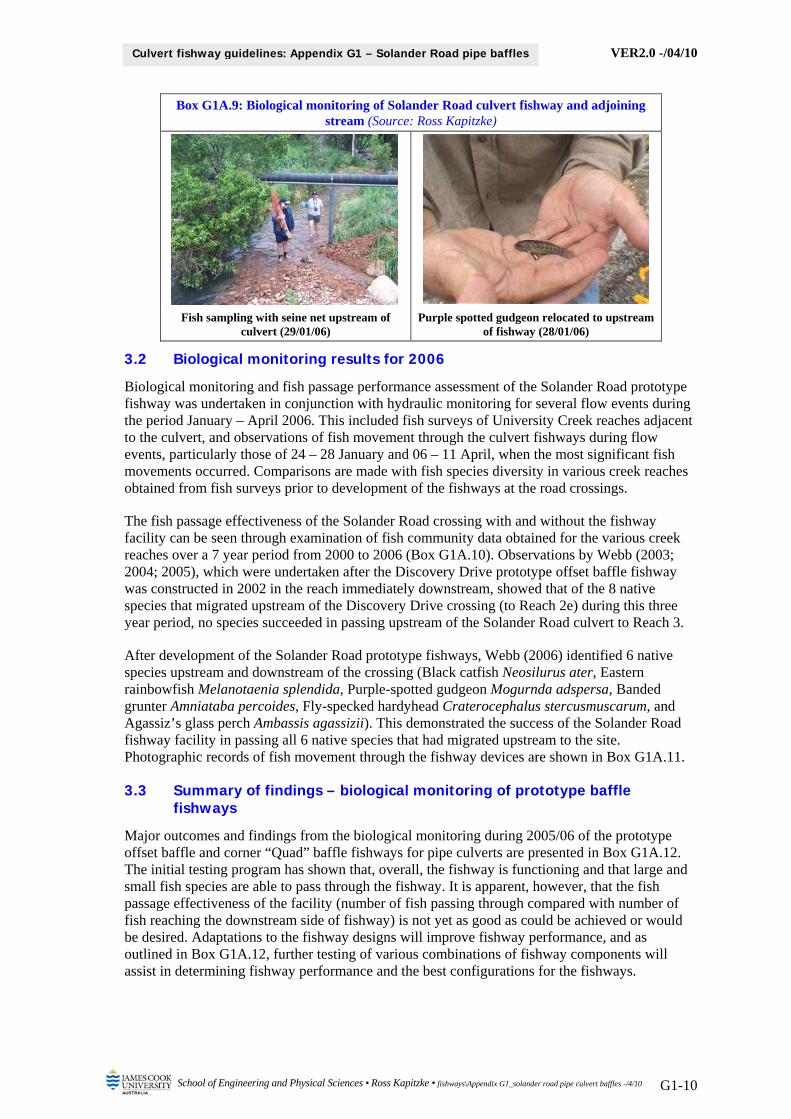
VER2.0 -/04/10
School of Engineering and Physical Sciences • Ross Kapitzke • fishways\Appendix G1_solander road pipe culvert baffles -/4/10 G1-10
Culvert fishway guidelines: Appendix G1 – Solander Road pipe baffles
Box G1A.9: Biological monitoring of Solander Road culvert fishway and adjoining stream (Source: Ross Kapitzke)
Fish sampling with seine net upstream of culvert (29/01/06)
Purple spotted gudgeon relocated to upstream of fishway (28/01/06)
3.2 Biological monitoring results for 2006
Biological monitoring and fish passage performance assessment of the Solander Road prototype fishway was undertaken in conjunction with hydraulic monitoring for several flow events during the period January – April 2006. This included fish surveys of University Creek reaches adjacent to the culvert, and observations of fish movement through the culvert fishways during flow events, particularly those of 24 – 28 January and 06 – 11 April, when the most significant fish movements occurred. Comparisons are made with fish species diversity in various creek reaches obtained from fish surveys prior to development of the fishways at the road crossings.
The fish passage effectiveness of the Solander Road crossing with and without the fishway facility can be seen through examination of fish community data obtained for the various creek reaches over a 7 year period from 2000 to 2006 (Box G1A.10). Observations by Webb (2003; 2004; 2005), which were undertaken after the Discovery Drive prototype offset baffle fishway was constructed in 2002 in the reach immediately downstream, showed that of the 8 native species that migrated upstream of the Discovery Drive crossing (to Reach 2e) during this three year period, no species succeeded in passing upstream of the Solander Road culvert to Reach 3.
After development of the Solander Road prototype fishways, Webb (2006) identified 6 native species upstream and downstream of the crossing (Black catfish Neosilurus ater, Eastern rainbowfish Melanotaenia splendida, Purple-spotted gudgeon Mogurnda adspersa, Banded grunter Amniataba percoides, Fly-specked hardyhead Craterocephalus stercusmuscarum, and Agassiz’s glass perch Ambassis agassizii). This demonstrated the success of the Solander Road fishway facility in passing all 6 native species that had migrated upstream to the site. Photographic records of fish movement through the fishway devices are shown in Box G1A.11.
3.3 Summary of findings – biological monitoring of prototype baffle fishways
Major outcomes and findings from the biological monitoring during 2005/06 of the prototype offset baffle and corner “Quad” baffle fishways for pipe culverts are presented in Box G1A.12. The initial testing program has shown that, overall, the fishway is functioning and that large and small fish species are able to pass through the fishway. It is apparent, however, that the fish passage effectiveness of the facility (number of fish passing through compared with number of fish reaching the downstream side of fishway) is not yet as good as could be achieved or would be desired. Adaptations to the fishway designs will improve fishway performance, and as outlined in Box G1A.12, further testing of various combinations of fishway components will assist in determining fishway performance and the best configurations for the fishways.
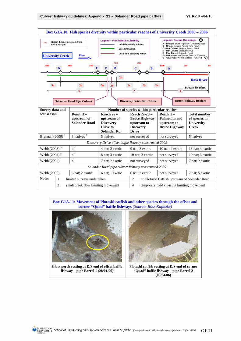
VER2.0 -/04/10
School of Engineering and Physical Sciences • Ross Kapitzke • fishways\Appendix G1_solander road pipe culvert baffles -/4/10 G1-11
Culvert fishway guidelines: Appendix G1 – Solander Road pipe baffles
Box G1A.10: Fish species diversity within particular reaches of University Creek 2000 – 2006
Survey data and wet season
Number of species within particular reaches Reach 3 – upstream of Solander Road
Reach 2e – upstream of Discovery Drive to Solander Rd
Reach 2a-2d – Bruce Highway upstream to Discovery Drive
Reach 1 – Palmetum and upstream to Bruce Highway
Total number of species in University Creek
Brennan (2000) 1 3 natives 2 5 natives not surveyed not surveyed 5 natives
Discovery Drive offset baffle fishway constructed 2002
Webb (2003) 3 nil 4 nat; 2 exotic 9 nat; 3 exotic 10 nat; 4 exotic 13 nat; 4 exotic
Webb (2004) 4 nil 8 nat; 3 exotic 10 nat; 3 exotic not surveyed 10 nat; 3 exotic
Webb (2005) nil 7 nat; ? exotic not surveyed not surveyed 7 nat; ? exotic
Solander Road pipe culvert fishway constructed 2005
Webb (2006) 6 nat; 2 exotic 6 nat; 1 exotic 6 nat; 3 exotic not surveyed 7 nat; 5 exotic
Notes 1 limited surveys undertaken 2 no Plotosid Catfish upstream of Solander Road
3 small creek flow limiting movement 4 temporary road crossing limiting movement
Box G1A.11: Movement of Plotosid catfish and other species through the offset and corner “Quad” baffle fishways (Source: Ross Kapitzke)
Glass perch resting at D/S end of offset baffle fishway – pipe Barrel 1 (28/01/06)
Plotosid catfish resting at D/S end of corner “Quad” baffle fishway – pipe Barrel 2
(09/04/06)
Flow University Creek
Ross River
00 500 1000
1500 Stream distance upstream from Ross River (m)
15002000250030003500
AF E D C BG
Stream Reaches3 1 2
2c 2b 2a3a3b 3c
2d
Legend – Fish habitat suitability Habitat generally suitable Excellent habitat Unsuitable spawning habitat
Legend - Stream Crossings A – Bridges: Bruce Highway – University Road B – Bridge: Douglas Arterial Ring Road C – Box Culvert: Hospital Access Road D – Box Culvert: Discovery Drive E – Pipe Culvert: Solander Road F – Footbridge: Vet/Biomed Science Walkway G – Causeway: Workshop Road - removed
Discovery Drive Box Culvert Solander Road Pipe Culvert Bruce Highway Bridges
2e
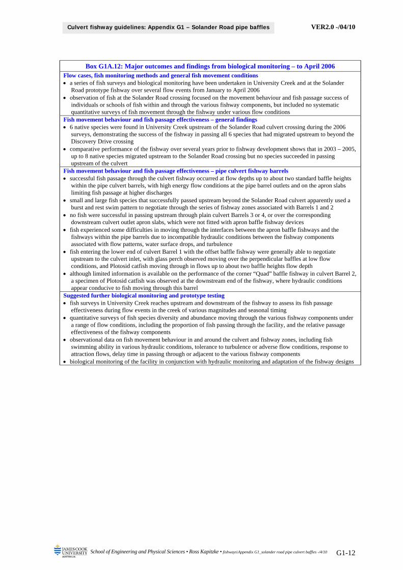
VER2.0 -/04/10
School of Engineering and Physical Sciences • Ross Kapitzke • fishways\Appendix G1_solander road pipe culvert baffles -/4/10 G1-12
Culvert fishway guidelines: Appendix G1 – Solander Road pipe baffles
Box G1A.12: Major outcomes and findings from biological monitoring – to April 2006 Flow cases, fish monitoring methods and general fish movement conditions a series of fish surveys and biological monitoring have been undertaken in University Creek and at the Solander
Road prototype fishway over several flow events from January to April 2006 observation of fish at the Solander Road crossing focused on the movement behaviour and fish passage success of
individuals or schools of fish within and through the various fishway components, but included no systematic quantitative surveys of fish movement through the fishway under various flow conditions
Fish movement behaviour and fish passage effectiveness – general findings 6 native species were found in University Creek upstream of the Solander Road culvert crossing during the 2006
surveys, demonstrating the success of the fishway in passing all 6 species that had migrated upstream to beyond the Discovery Drive crossing
comparative performance of the fishway over several years prior to fishway development shows that in 2003 – 2005, up to 8 native species migrated upstream to the Solander Road crossing but no species succeeded in passing upstream of the culvert
Fish movement behaviour and fish passage effectiveness – pipe culvert fishway barrels successful fish passage through the culvert fishway occurred at flow depths up to about two standard baffle heights
within the pipe culvert barrels, with high energy flow conditions at the pipe barrel outlets and on the apron slabs limiting fish passage at higher discharges
small and large fish species that successfully passed upstream beyond the Solander Road culvert apparently used a burst and rest swim pattern to negotiate through the series of fishway zones associated with Barrels 1 and 2
no fish were successful in passing upstream through plain culvert Barrels 3 or 4, or over the corresponding downstream culvert outlet apron slabs, which were not fitted with apron baffle fishway devices
fish experienced some difficulties in moving through the interfaces between the apron baffle fishways and the fishways within the pipe barrels due to incompatible hydraulic conditions between the fishway components associated with flow patterns, water surface drops, and turbulence
fish entering the lower end of culvert Barrel 1 with the offset baffle fishway were generally able to negotiate upstream to the culvert inlet, with glass perch observed moving over the perpendicular baffles at low flow conditions, and Plotosid catfish moving through in flows up to about two baffle heights flow depth
although limited information is available on the performance of the corner “Quad” baffle fishway in culvert Barrel 2, a specimen of Plotosid catfish was observed at the downstream end of the fishway, where hydraulic conditions appear conducive to fish moving through this barrel
Suggested further biological monitoring and prototype testing fish surveys in University Creek reaches upstream and downstream of the fishway to assess its fish passage
effectiveness during flow events in the creek of various magnitudes and seasonal timing quantitative surveys of fish species diversity and abundance moving through the various fishway components under
a range of flow conditions, including the proportion of fish passing through the facility, and the relative passage effectiveness of the fishway components
observational data on fish movement behaviour in and around the culvert and fishway zones, including fish swimming ability in various hydraulic conditions, tolerance to turbulence or adverse flow conditions, response to attraction flows, delay time in passing through or adjacent to the various fishway components
biological monitoring of the facility in conjunction with hydraulic monitoring and adaptation of the fishway designs
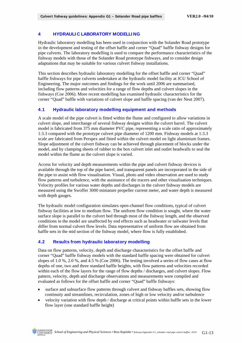
VER2.0 -/04/10
School of Engineering and Physical Sciences • Ross Kapitzke • fishways\Appendix G1_solander road pipe culvert baffles -/4/10 G1-13
Culvert fishway guidelines: Appendix G1 – Solander Road pipe baffles
4 HYDRAULIC LABORATORY MODELLING
Hydraulic laboratory modelling has been used in conjunction with the Solander Road prototype in the development and testing of the offset baffle and corner “Quad” baffle fishway designs for pipe culverts. The laboratory modelling is used to compare the performance characteristics of the fishway models with those of the Solander Road prototype fishways, and to consider design adaptations that may be suitable for various culvert fishway installations.
This section describes hydraulic laboratory modelling for the offset baffle and corner “Quad” baffle fishways for pipe culverts undertaken at the hydraulic model facility at JCU School of Engineering. The major outcomes and findings for the work until 2006 are summarised, including flow patterns and velocities for a range of flow depths and culvert slopes in the fishways (Coe 2006). More recent modelling has examined hydraulic characteristics for the corner “Quad” baffle with variations of culvert slope and baffle spacing (van der Neut 2007).
4.1 Hydraulic laboratory modelling equipment and methods
A scale model of the pipe culvert is fitted within the flume and configured to allow variations in culvert slope, and interchange of several fishway designs within the culvert barrel. The culvert model is fabricated from 375 mm diameter PVC pipe, representing a scale ratio of approximately 1:3.3 compared with the prototype culvert pipe diameter of 1200 mm. Fishway models at 1:3.3 scale are fabricated from Perspex and fitted within the culvert model on light aluminium frames. Slope adjustment of the culvert fishway can be achieved through placement of blocks under the model, and by clamping sheets of rubber to the box culvert inlet and outlet headwalls to seal the model within the flume as the culvert slope is varied.
Access for velocity and depth measurements within the pipe and culvert fishway devices is available through the top of the pipe barrel, and transparent panels are incorporated in the side of the pipe to assist with flow visualisation. Visual, photo and video observation are used to study flow patterns and turbulence, with the assistance of die tracers and other visualisation techniques. Velocity profiles for various water depths and discharges in the culvert fishway models are measured using the Swoffer 3000 miniature propeller current meter, and water depth is measured with depth gauges.
The hydraulic model configuration simulates open-channel flow conditions, typical of culvert fishway facilities at low to medium flow. The uniform flow condition is sought, where the water surface slope is parallel to the culvert bed through most of the fishway length, and the observed conditions in the model are unaffected by end effects such as headwater or tailwater levels that differ from normal culvert flow levels. Data representative of uniform flow are obtained from baffle sets in the mid section of the fishway model, where flow is fully established.
4.2 Results from hydraulic laboratory modelling
Data on flow patterns, velocity, depth and discharge characteristics for the offset baffle and corner “Quad” baffle fishway models with the standard baffle spacing were obtained for culvert slopes of 1.0 %, 2.0 %, and 4.5 % (Coe 2006). The testing involved a series of flow cases at flow depths of one, two and three standard baffle heights, with flow patterns and velocities recorded within each of the flow layers for the range of flow depths / discharges, and culvert slopes. Flow pattern, velocity, depth and discharge observations and measurements were compiled and evaluated as follows for the offset baffle and corner “Quad” baffle fishways:
surface and subsurface flow patterns through culvert and fishway baffles sets, showing flow continuity and streamlines, recirculation, zones of high or low velocity and/or turbulence
velocity variation with flow depth / discharge at critical points within baffle sets in the lower flow layer (one standard baffle height)
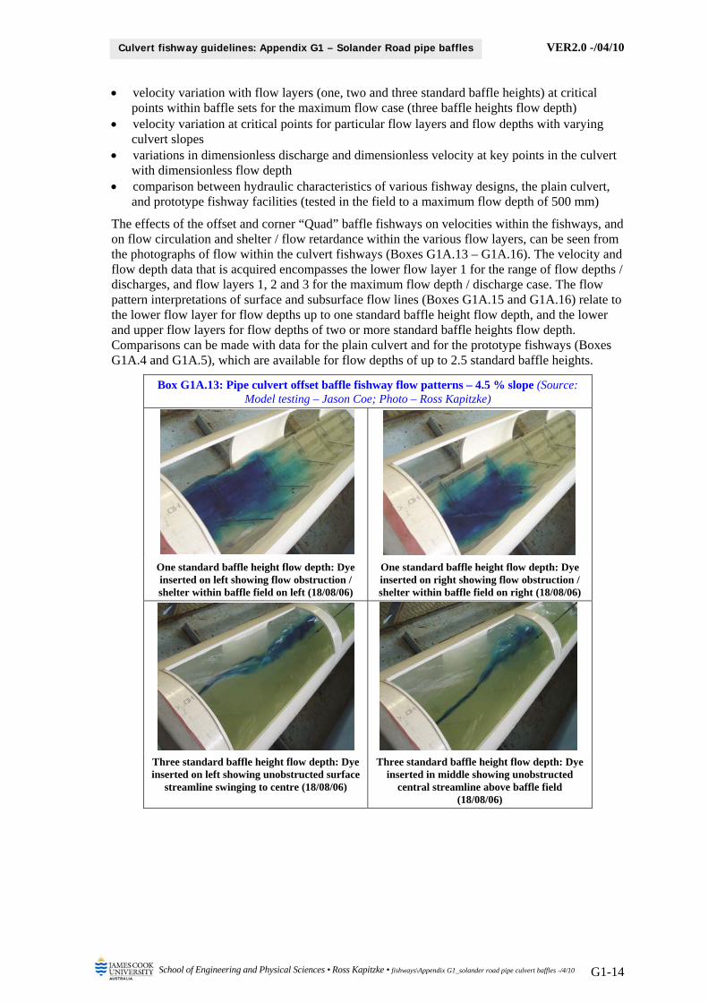
VER2.0 -/04/10
School of Engineering and Physical Sciences • Ross Kapitzke • fishways\Appendix G1_solander road pipe culvert baffles -/4/10 G1-14
Culvert fishway guidelines: Appendix G1 – Solander Road pipe baffles
velocity variation with flow layers (one, two and three standard baffle heights) at critical points within baffle sets for the maximum flow case (three baffle heights flow depth)
velocity variation at critical points for particular flow layers and flow depths with varying culvert slopes
variations in dimensionless discharge and dimensionless velocity at key points in the culvert with dimensionless flow depth
comparison between hydraulic characteristics of various fishway designs, the plain culvert, and prototype fishway facilities (tested in the field to a maximum flow depth of 500 mm)
The effects of the offset and corner “Quad” baffle fishways on velocities within the fishways, and on flow circulation and shelter / flow retardance within the various flow layers, can be seen from the photographs of flow within the culvert fishways (Boxes G1A.13 – G1A.16). The velocity and flow depth data that is acquired encompasses the lower flow layer 1 for the range of flow depths / discharges, and flow layers 1, 2 and 3 for the maximum flow depth / discharge case. The flow pattern interpretations of surface and subsurface flow lines (Boxes G1A.15 and G1A.16) relate to the lower flow layer for flow depths up to one standard baffle height flow depth, and the lower and upper flow layers for flow depths of two or more standard baffle heights flow depth. Comparisons can be made with data for the plain culvert and for the prototype fishways (Boxes G1A.4 and G1A.5), which are available for flow depths of up to 2.5 standard baffle heights.
Box G1A.13: Pipe culvert offset baffle fishway flow patterns – 4.5 % slope (Source: Model testing – Jason Coe; Photo – Ross Kapitzke)
One standard baffle height flow depth: Dye inserted on left showing flow obstruction / shelter within baffle field on left (18/08/06)
One standard baffle height flow depth: Dye inserted on right showing flow obstruction / shelter within baffle field on right (18/08/06)
Three standard baffle height flow depth: Dye inserted on left showing unobstructed surface
streamline swinging to centre (18/08/06)
Three standard baffle height flow depth: Dye inserted in middle showing unobstructed
central streamline above baffle field (18/08/06)
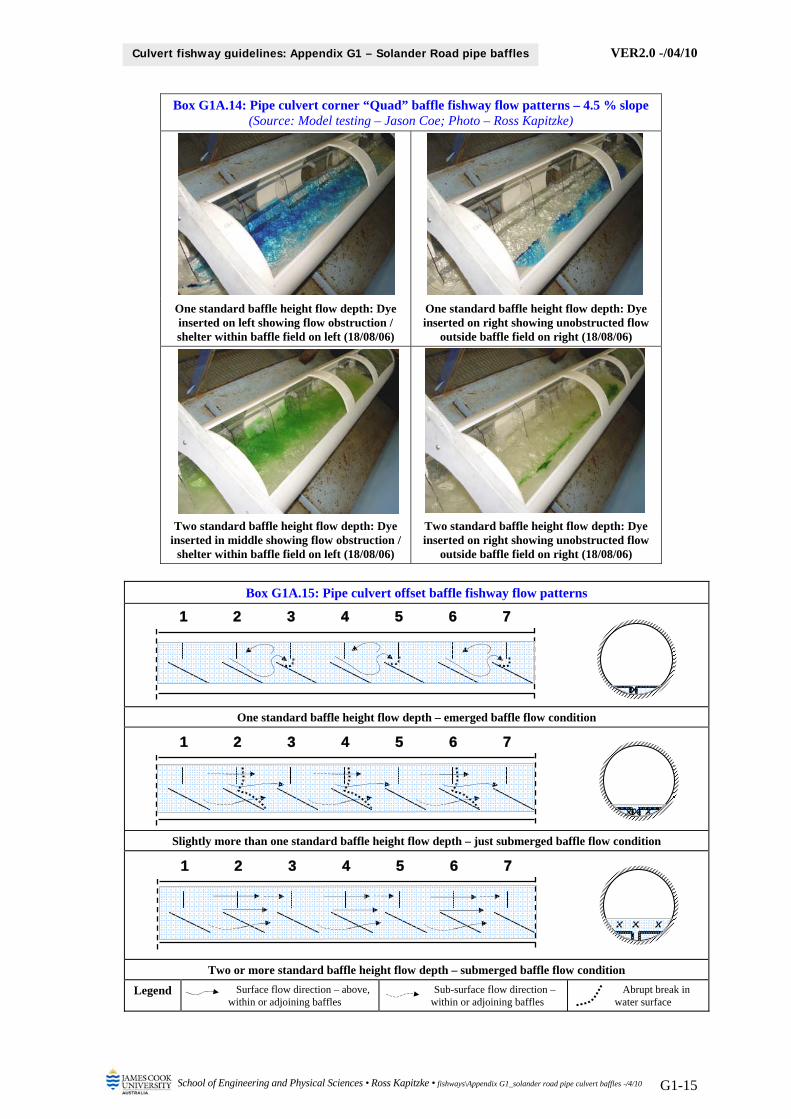
VER2.0 -/04/10
School of Engineering and Physical Sciences • Ross Kapitzke • fishways\Appendix G1_solander road pipe culvert baffles -/4/10 G1-15
Culvert fishway guidelines: Appendix G1 – Solander Road pipe baffles
Box G1A.14: Pipe culvert corner “Quad” baffle fishway flow patterns – 4.5 % slope (Source: Model testing – Jason Coe; Photo – Ross Kapitzke)
One standard baffle height flow depth: Dye inserted on left showing flow obstruction / shelter within baffle field on left (18/08/06)
One standard baffle height flow depth: Dye inserted on right showing unobstructed flow
outside baffle field on right (18/08/06)
Two standard baffle height flow depth: Dye inserted in middle showing flow obstruction /
shelter within baffle field on left (18/08/06)
Two standard baffle height flow depth: Dye inserted on right showing unobstructed flow
outside baffle field on right (18/08/06)
Box G1A.15: Pipe culvert offset baffle fishway flow patterns
One standard baffle height flow depth – emerged baffle flow condition
Slightly more than one standard baffle height flow depth – just submerged baffle flow condition
Two or more standard baffle height flow depth – submerged baffle flow condition
Legend Surface flow direction – above, within or adjoining baffles
Sub-surface flow direction – within or adjoining baffles
Abrupt break in water surface
1 2 3 4 5 6 7
1 2 3 4 5 6 7
1 2 3 4 5 6 7
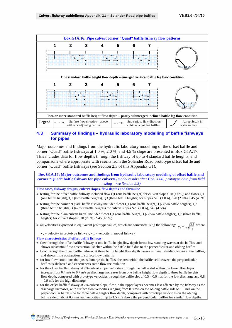
VER2.0 -/04/10
School of Engineering and Physical Sciences • Ross Kapitzke • fishways\Appendix G1_solander road pipe culvert baffles -/4/10 G1-16
Culvert fishway guidelines: Appendix G1 – Solander Road pipe baffles
Box G1A.16: Pipe culvert corner “Quad” baffle fishway flow patterns
One standard baffle height flow depth – emerged vertical baffle leg flow condition
Two or more standard baffle height flow depth – partly submerged inclined baffle leg flow condition
Legend Surface flow direction – above, within or adjoining baffles
Sub-surface flow direction – within or adjoining baffles
Abrupt break in water surface
4.3 Summary of findings – hydraulic laboratory modelling of baffle fishways for pipes
Major outcomes and findings from the hydraulic laboratory modelling of the offset baffle and corner “Quad” baffle fishways at 1.0 %, 2.0 %, and 4.5 % slope are presented in Box G1A.17. This includes data for flow depths through the fishway of up to 4 standard baffle heights, and comparisons where appropriate with results from the Solander Road prototype offset baffle and corner “Quad” baffle fishways (see Section 2.3 of this Appendix G1).
Box G1A.17: Major outcomes and findings from hydraulic laboratory modeling of offset baffle and corner “Quad” baffle fishway for pipe culverts (model results after Coe 2006; prototype data from field
testing – see Section 2.3) Flow cases, fishway designs, culvert slopes, flow depths and formulae
testing for the offset baffle fishway included flow Q1 (one baffle height) for culvert slope S10 (1.0%); and flows Q1 (one baffle height), Q2 (two baffle heights), Q3 (three baffle heights) for slopes S10 (1.0%), S20 (2.0%), S45 (4.5%)
testing for the corner “Quad” baffle fishway included flows Q1 (one baffle height), Q2 (two baffle heights), Q3 (three baffle heights), Q4 (four baffle heights) for culvert slopes S20 (2.0%), S45 (4.5%)
testing for the plain culvert barrel included flows Q1 (one baffle height), Q2 (two baffle heights), Q3 (three baffle heights) for culvert slopes S20 (2.0%), S45 (4.5%)
all velocities expressed in equivalent prototype values, which are converted using the following: 1
3.3mp vv where
vp = velocity in prototype fishway; vm = velocity in model fishway
Flow characteristics of offset baffle fishway flow through the offset baffle fishway at one baffle height flow depth forms low standing waves at the baffles, and
shows substantial flow obstruction / shelter within the baffle field due to the perpendicular and oblong baffles flow through the offset baffle fishway at three baffle height flow depth causes minimal standing waves at the baffles,
and shows little obstruction to surface flow patterns for low flow conditions that just submerge the baffles, the area within the baffle cell between the perpendicular
baffles is sheltered and experiences some flow recirculation for the offset baffle fishway at 2% culvert slope, velocities through the baffle slot within the lower flow layer
increase from 0.4 m/s to 0.7 m/s as discharge increases from one baffle height flow depth to three baffle heights flow depth, compared with prototype velocities through the baffle slot of 0.5 – 0.6 m/s for the low discharge and 0.8 – 0.9 m/s for the high discharge
for the offset baffle fishway at 2% culvert slope, flow in the upper layers becomes less affected by the fishway as the discharge increases, with surface flow velocities ranging from 0.8 m/s on the oblong baffle side to 1.0 m/s on the perpendicular baffle side for three baffle heights flow depth, compared with prototype velocities on the oblong baffle side of about 0.7 m/s and velocities of up to 1.5 m/s above the perpendicular baffles for similar flow depths
1 2 3 4 5 6 7
1 2 3 4 5 6 7
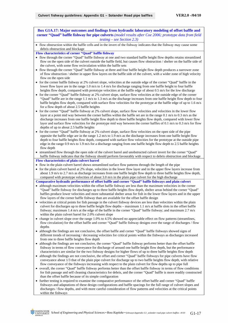
VER2.0 -/04/10
School of Engineering and Physical Sciences • Ross Kapitzke • fishways\Appendix G1_solander road pipe culvert baffles -/4/10 G1-17
Culvert fishway guidelines: Appendix G1 – Solander Road pipe baffles
Box G1A.17: Major outcomes and findings from hydraulic laboratory modeling of offset baffle and corner “Quad” baffle fishway for pipe culverts (model results after Coe 2006; prototype data from field
testing – see Section 2.3) flow obstruction within the baffle cells and in the invert of the fishway indicates that the fishway may cause some
debris obstruction and blockage Flow characteristics of corner “Quad” baffle fishway flow through the corner “Quad” baffle fishway at one and two standard baffle height flow depths retains streamlined
flow on the open side of the culvert outside the baffle field, but causes flow obstruction / shelter on the baffle side of the culvert, with some flow recirculation within the baffle sets
flow through the corner “Quad” baffle fishway at three and four baffle height flow depth produces a narrower zone of flow obstruction / shelter in upper flow layers on the baffle side of the culvert, with a wider zone of high velocity flow on the open side
for the corner baffle fishway at 2% culvert slope, velocities at the outside edge of the corner “Quad” baffle in the lower flow layer are in the range 1.0 m/s to 1.4 m/s for discharge ranging from one baffle height to four baffle heights flow depth, compared with prototype velocities at the baffle edge of about 0.5 m/s for the low discharge
for the corner “Quad” baffle fishway at 2% culvert slope, surface flow velocities at the outside edge of the corner “Quad” baffle are in the range 1.1 m/s to 1.3 m/s as the discharge increases from one baffle height flow depth to four baffle heights flow depth, compared with surface flow velocities for the prototype at the baffle edge of up to 1.6 m/s for a flow depth of about 2.5 baffle heights
for the corner “Quad” baffle fishway at 2% culvert slope, surface flow velocities and velocities in the lower flow layer at a point mid way between the corner baffles within the baffle set are in the range 0.1 m/s to 0.3 m/s as the discharge increases from one baffle height flow depth to three baffle heights flow depth, compared with lower flow layer and surface flow velocities for the prototype mid way between the corner baffles of 0.1 m/s to 0.3 m/s for flow depths of up to about 2.5 baffle heights
for the corner “Quad” baffle fishway at 2% culvert slope, surface flow velocities on the open side of the pipe opposite the baffle edge are in the range 1.2 m/s to 1.9 m/s as the discharge increases from one baffle height flow depth to four baffle heights flow depth, compared with surface flow velocities for the prototype at the outside pipe edge in the range 0.9 m/s to 1.9 m/s for a discharge ranging from one baffle height flow depth to 2.5 baffle heights flow depth
streamlined flow through the open side of the culvert barrel and unobstructed culvert invert for the corner “Quad” baffle fishway indicates that the fishway should perform favourably with respect to debris obstruction and blockage
Flow characteristics of plain culvert barrel flow in the plain culvert barrel shows streamlined surface flow patterns through the length of the pipe for the plain culvert barrel at 2% slope, velocities in the lower flow layer and in the upper flow layers increase from
about 1.9 m/s to 2.7 m/s as discharge increases from one baffle height flow depth to three baffle heights flow depth, compared with prototype velocities of about 3.0 m/s in the plain pipe culvert for the high discharge
Comparative hydraulic performance of offset baffle and corner “Quad” baffle fishways and plain culvert although maximum velocities within the offset baffle fishway are less than the maximum velocities in the corner
“Quad” baffle fishway for discharges up to three baffle heights flow depth, shelter areas behind the corner “Quad” baffles produce lower velocities and more substantial shelter areas for fish in the lower flow layers and in the upper flow layers of the corner baffle fishway than are available for the offset baffle design
velocities at critical points for fish passage in the culvert fishway devices are less than velocities within the plain culvert for discharges up to three baffle height flow depths – maximum 1.1 m/s at baffle slots in the offset baffle fishway; maximum 1.4 m/s at the edge of the baffle in the corner “Quad” baffle fishway; and maximum 2.7 m/s within the plain culvert barrel for 2.0% culvert slope
change in culvert slope over the range 1.0% to 4.5% showed no appreciable effect on flow patterns (streamlines, flow circulation) for the offset baffle and corner “Quad” baffle fishway designs over the range of discharges / flow depths
although the findings are not conclusive, the offset baffle and corner “Quad” baffle fishways showed signs of different trends of increasing / decreasing velocities for critical points within the fishways as discharges increased from one to three baffle heights flow depth
although the findings are not conclusive, the corner “Quad” baffle fishway performs better than the offset baffle fishway in terms of flow conveyance for discharge of around one baffle height flow depth, but the performance characteristics are similar for the two fishway designs for higher flows of up to three baffle heights flow depth
although the findings are not conclusive, the offset and corner “Quad” baffle fishways for pipe culverts have flow conveyance about 1/3 that of the plain pipe culvert for discharge up to two baffle heights flow depth, with relative flow conveyance of the fishways increasing with respect to the plain culvert for flow depths up to pipe full
overall, the corner “Quad” baffle fishway performs better than the offset baffle fishway in terms of flow conditions for fish passage and self cleaning characteristics for debris, and the corner “Quad” baffle is more readily constructed than the offset baffle because of its simple configuration
further testing is required to examine the comparative performance of the offset baffle and corner “Quad” baffle fishways and adaptations of these design configurations and baffle spacings for the full range of culvert slopes and discharges / flow depths, and with more careful consideration of flow patterns and velocities at the critical points within the fishways

VER2.0 -/04/10
School of Engineering and Physical Sciences • Ross Kapitzke • fishways\Appendix G1_solander road pipe culvert baffles -/4/10 G1-18
Culvert fishway guidelines: Appendix G1 – Solander Road pipe baffles
5 BIBLIOGRAPHY Engel, P. 1974, Fish facilities for culverts of the McKenzie Highway, National Water Research Institute,
Burlington Ontario 33p. Coe, J. 2006, Performance characteristics of offset baffle and corner baffle fishways for pipe culverts,
Bachelor of Engineering Thesis, James Cook University School of Engineering. Kapitzke, I.R. 2006a, Bruce Highway Corduroy Creek to Tully planning study Provisions for fish passage
– Road corridor scale Assessment Task 1A, report to Maunsell Australia and Department of Main Roads. Kapitzke, I.R. 2006b, Discovery Drive offset baffle fishway for box culverts (Prototype Fishway # 1): Case
study project design and prototype monitoring report to April 2005, report to Dept of Main Roads. Kapitzke, I.R. 2006c, Douglas Arterial Project rock ramp fishway for open channels (Prototype Fishway #
2): Case study project design and prototype monitoring report to April 2005, report to Dept Main Roads. Kapitzke, I.R. 2007a, Bruce Highway Corduroy Creek to Tully High School Provisions for fish passage –
Preliminary Design Assessment Tasks 1B and 2, report to Maunsell Australia and Dept of Main Roads. Kapitzke, I.R. 2007b, Discovery Drive corner baffle fishway for box culverts (Prototype Fishway # 4):
Case study project design and prototype monitoring report to April 2006, report to Dept of Main Roads. Kapitzke, I.R. 2007c, Solander Road pipe culvert fishway (Prototype Fishway # 3): Case study project
design and prototype monitoring report to April 2006, report to Department of Main Roads. Van der Neut, C. 2007, Design adaptations for corner baffle fishways for pipe culverts, Bachelor of
Engineering Thesis, James Cook University School of Engineering. Webb, A.C. 2006, Fishway biomonitoring January – April 2006, report prepared by James Cook
University School of Tropical Biology.
Ross Kapitzke James Cook University School of Engineering and Physical Sciences April 2010 – VER2.0