first-principles prediction of spin-polarized multiple ... · pdf filefirst-principles...
TRANSCRIPT
First-Principles Prediction of Spin-Polarized Multiple Dirac Rings in Manganese Fluoride
Yalong Jiao,1 Fengxian Ma,1 Chunmei Zhang,1 John Bell,1 Stefano Sanvito,2 and Aijun Du1,*1School of Chemistry, Physics and Mechanical Engineering, Queensland University of Technology,
Gardens Point Campus, Brisbane, Queensland 4001, Australia2School of Physics, AMBER and CRANN Institute, Trinity College, Dublin 2, Ireland
(Received 7 February 2017; revised manuscript received 14 May 2017; published 7 July 2017)
Spin-polarized materials with Dirac features have sparked great scientific interest due to their potentialapplications in spintronics. But such a type of structure is very rare and none has been fabricated. Here, weinvestigate the already experimentally synthesizedmanganese fluoride (MnF3) as a novel spin-polarized Diracmaterial by using first-principles calculations. MnF3 exhibits multiple Dirac cones in one spin orientation,while it behaves like a large gap semiconductor in the other spin channel. The estimated Fermivelocity for eachcone is of the same order of magnitude as that in graphene. The 3D band structure further reveals that MnF3possesses rings of Dirac nodes in the Brillouin zone. Such a spin-polarized multiple Dirac ring feature isreported for the first time in an experimentally realizedmaterial.Moreover, similar band dispersions can be alsofound in other transition metal fluorides (e.g., CoF3, CrF3, and FeF3). Our results highlight a new interestingsingle-spin Dirac material with promising applications in spintronics and information technologies.
DOI: 10.1103/PhysRevLett.119.016403
Ever since the spin and charge of one electron have beenconsidered separately, it has been found that the spin currentdisplays superior properties to the classical charge current inthe field of information transmission such as high speed, lowpower consumption, and negligible energy dissipation [1].Thus, the corresponding spin current has drawn greatattention over the past few decades and the spin electronicsare rapidly expanding [2–11]. Up to now, a number ofspintronics materials have been proposed includingmagneticmetals, half-metallic ferromagnets, topological insulators,magnetic semiconductors, diluted magnetic semiconductors,etc. [12–16]. But to exploit the full potential of spintronicsin information transfer and storage, some basic issues stillremain, such as long distance spin transport, and the gen-eration and injection of spin polarized currents [4,17,18].In addition to them, the grand challenges for new generationspintronics are how tomake electrons transportwith ultrahighspeed and consume ultralow energy, which requires realizingmassless electrons by discovering the potential Dirac banddispersion, and achieve dissipationless spin transport viagenerating large spin polarization around theFermi level [19].It is necessary to emphasize that the well-studied materi-
als for spintronics such as half-metals, can meet the “basic”demand of spintronics applications [20,21]. In addition,Wang [22] proposed a new class of materials named spingapless semiconductors (SGS) that can generate 100% spinpolarized current and is promising in spintronics. The SGSwas then validated by Ouardi et al. in experiment [23].However, to overcome the “grand challenge,” the perfor-mances of half-metal and SGS are still limited as it justbehaves like a metal-semiconductor in one spin orientation,but lacks linear Dirac dispersion, which can hardly reach thegoal of ultrahigh speed spin transport. Therefore, it is ofgreat interest to explore new platforms with spin-polarized
linear energy dispersion (Dirac half-metal) and masslessDirac fermions, which will lead towards realistic appli-cations in high effieciency spintronics and quantum infor-mation technologies [19,24,25]. Dirac materials withspin-polarized band structures can effectively utilize spindegrees of freedom of electrons. They can also break theprotection of time-reversal symmetry (TRS) but maintain thelinear relation of energy-momentum dispersion at the Fermilevel, resulting in outstanding transport properties. Such atype of material was theoretically proposed in a triangularferrimagnet in recent years [24], but this novel class ofstructures is very rare and has only been predicted in a limitednumber of configurations such as CrO2=TiO2 heterostructure[26], Mn-intercalated graphene [13], and the NiCl3 mono-layer [27]. Yet no Dirac half-metal has been experimentallysynthesized [28]. Therefore, the search for spin-polarizedDirac materials with a high possibility of experimentalrealization is under the spotlight in spin electronics.The MnF3 crystal has been fabricated for many years, but
no theoretical work reveals its electronic band structurebefore. In this Letter, we present the experimentally syn-thesized spin-polarized Dirac material (MnF3) with promis-ing applications in spintronics. It displays Dirac features inone spin channel, while it possesses a large gap (7.8 eV) in theother spin orientation. This guarantees the generation of aspin-polarized current and spin transport with negligibledissipation. In addition, MnF3 displays multiple Dirac conesin the band structure instead of a single Dirac cone, and theestimated Fermi velocity of each cone is close to that found ingraphene. Strikingly, it exhibits novel rings of Dirac nodes(see Fig. 3) in the Brillouin zone (BZ), which has not beenreported in either spin-polarized or conventional Diracmaterials. This multiple Dirac ring band dispersion is ex-pected to have more intensive nonlinear electromagnetic
PRL 119, 016403 (2017) P HY S I CA L R EV I EW LE T T ER Sweek ending7 JULY 2017
0031-9007=17=119(1)=016403(6) 016403-1 © 2017 American Physical Society
responses [29] than Dirac materials with a single cone, andpossess a higher efficiency of carrier transport at the Fermilevel via the multiple Dirac channels. Moreover, as the spin-orbital coupling (SOC) is very low in MnF3, it can easilyrealize the long distance spin transport for spintronics.Furthermore, we have discovered that the unique electronicproperties of MnF3 are also present in other transition metalfluorides including CoF3, CrF3, and FeF3. The MnF3-typeconfiguration is expected to be a highly prospective class ofcandidates for spintronics and enrich the family of novelelectronics materials.All the calculations were performed using density func-
tional theory (DFT) within the Perdew-Burke-Ernzerhof(PBE) parametrization of the generalized gradient approxi-mation (GGA) [30], as implemented in the VASP code[31,32]. Dispersion corrections to the total energy [33]were used to incorporate the long-range van der Waalsinteraction. A plane-wave basis set with an energy cutoff of500 eV was employed. The structures were fully optimizeduntil the maximum energy and force were less than10−6 eV and 0.005 eV=Å, respectively. A Monkhorst-Pack k-point mesh of 6 × 6 × 2 was used for geometryoptimization. Spin polarization was included through allthe calculations and SOC was also considered. Theelectronic properties of MnF3 have also been examinedby using the DFTþ U method [34] and the state-of-the-artHeyd-Scuseria-Ernzerhof (HSE06) functional [35].The well-studied manganese fluorides [36] include
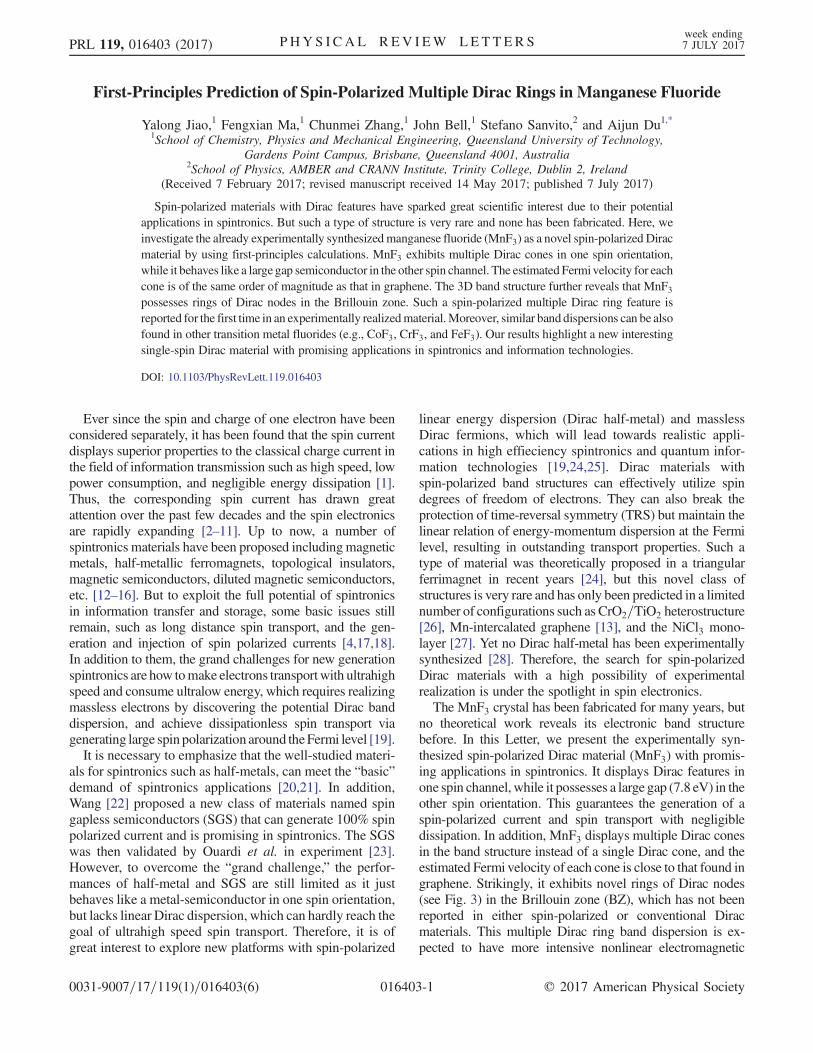
α-MnF4 (space group, I41=a, no. 88) and α-MnF3 (spacegroup,C2=c, No.15). However, little theoretical research hasfocused on another phase MnF3 (also named β-MnF4 inliterature) [37,38] despite its experimental synthesis manyyears ago. The crystal structure of MnF3 bulk in this workresembles the vanadium (III) fluoride (VF3) structure type inthe hexagonal R-3c space group (no. 167). It containsoctahedrally coordinated metal centers with the equal M-Fbond lengths of 1.930 Å [Fig. 1(a)]. The optimized latticeconstants for MnF3 are a ¼ b ¼ 5.20 Å and c ¼ 13.46 Å,respectively. These values are relatively larger than theexperimental lattice parameters with a ¼ b ¼ 4.892 Å andc ¼ 13.0 Å. The unit cell contains 6 Mn and 18 F atoms,respectively. The magnetic moment is found to be 4 μB performula unit, which ismainly attributed to the transitionmetalMn atoms. This can be further verified by plotting the 3Dmagnetic charge density as shown in Fig. 1(b). Clearly, allmagneticmoments are localized aroundMnatoms, indicatingthese atoms are responsible for the magnetic nature of MnF3.To determine themagnetic ground state ofMnF3, an energy
comparison was made among three different configurations:ferromagnetic (FM), antiferromagnetic (AFM) as well as thenonmagnetic (NM) system.Differentmagnetic configurationsin the 2 × 2 × 1 and 1 × 1 × 2 supercell, and 1 × 1 × 1 unitcell are presented in Figs. S1–S3 of the SupplementalMaterial[39]. We found the optimized FM state is most energeticallystable in all magnetic configurations and it has lower energythan that of the AFM andNM states, respectively. In addition,
the remarkable energy difference between FM and NM statesindicates very strong magnetism in MnF3.Having identified the magnetic ground state of MnF3, the
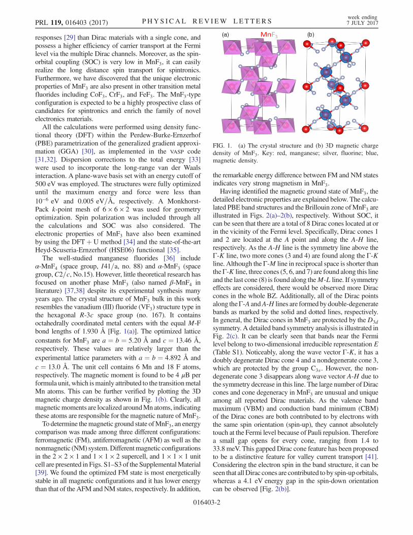
detailed electronic properties are explained below. The calcu-lated PBE band structures and the Brillouin zone ofMnF3 areillustrated in Figs. 2(a)–2(b), respectively. Without SOC, itcan be seen that there are a total of 8 Dirac cones located at orin the vicinity of the Fermi level. Specifically, Dirac cones 1and 2 are located at the A point and along the A-H line,respectively. As the A-H line is the symmetry line above theΓ-K line, two more cones (3 and 4) are found along the Γ-Kline. Although the Γ-M line in reciprocal space is shorter thantheΓ-K line, three cones (5, 6, and 7) are found along this lineand the last cone (8) is found along theM-L line. If symmetryeffects are considered, there would be observed more Diraccones in the whole BZ. Additionally, all of the Dirac pointsalong theΓ-A andA-H lines are formedbydouble-degeneratebands as marked by the solid and dotted lines, respectively.In general, the Dirac cones in MnF3 are protected by theD3dsymmetry. A detailed band symmetry analysis is illustrated inFig. 2(c). It can be clearly seen that bands near the Fermilevel belong to two-dimensional irreducible representation E(Table S1). Noticeably, along the wave vector Γ-K, it has adoubly degenerate Dirac cone 4 and a nondegenerate cone 3,which are protected by the group C3v. However, the non-degenerate cone 3 disappears along wave vector A-H due tothe symmetry decrease in this line. The large number of Diraccones and cone degeneracy in MnF3 are unusual and uniqueamong all reported Dirac materials. As the valence bandmaximum (VBM) and conduction band minimum (CBM)of the Dirac cones are both contributed to by electrons withthe same spin orientation (spin-up), they cannot absolutelytouch at the Fermi level because of Pauli repulsion. Thereforea small gap opens for every cone, ranging from 1.4 to33.8 meV. This gapped Dirac cone feature has been proposedto be a distinctive feature for valley current transport [41].Considering the electron spin in the band structure, it can beseen that allDirac cones are contributed to by spin-uporbitals,whereas a 4.1 eV energy gap in the spin-down orientationcan be observed [Fig. 2(b)].
FIG. 1. (a) The crystal structure and (b) 3D magnetic chargedensity of MnF3. Key: red, manganese; silver, fluorine; blue,magnetic density.
PRL 119, 016403 (2017) P HY S I CA L R EV I EW LE T T ER Sweek ending7 JULY 2017
016403-2
When SOC is switched on (Fig. S4 [39]), the lineardispersion of the Dirac cones is hardly affected, onlyleading to the slight value variation (2.0–15.0 meV) ofthe opened gaps. In addition, it is also interesting thatseveral Dirac-like crossing points [illustrated in Fig. 2(a)by black squares] are also found above or below the Fermilevel. These points are preserved when SOC is considered,which is similar to observations in ZrSiS [42]. As the SOCeffect is not significant in its impact on electronic structure,it is expected that MnF3 possesses a long spin coherencelength, and will be an ideal material for spin transport.It should be noted that the standard DFT is unable to accu-
rately describe the physics of the magnetic transition metal(Mn) with strong correlated d electrons. The DFTþ U me-thod is therefore used to examine the band structure ofMnF3.In the spin-up orientation, the DFTþ U band structure hasnegligible difference compared with the PBE bands (Fig. S5ain the Supplemental Material [39]). But for the spin-downchannel, the effect of strongcorrelationofd electrons push theVBM to lower energy and the CBM to higher energy(Fig. S5b [39]), resulting in a larger energy gap of 5.5 eV.In addition to the DFTþ U approach, the highly reliable
HSE06 hybrid functional was also employed to yield moreaccurate band dispersion for MnF3. As shown in Fig. 2(c),the HSE band curves in the spin-up direction are similar withthat of the PBE results, only leading to a slight gap opening ofsome cones (up to 53.5 meV). It also causes the extensionzof bands in energy. For example, the energy difference ofbandL1 andL2 at theΓ point is 3.2 eV by theHSE06method
[Fig. 2(c)] while it is only 2.4 eVaccording to the PBE result[Fig. 2(a)]. As for the spin-down channel, the HSE06calculation produces a larger energy gap (7.8 eV) comparedwith that of the PBE method. To the best of our knowledge,such a substantial energy difference between spin-up andspin-down states has not been reported before and it alsodemonstrates the spin-down electrons behave like a largegap semiconductor in MnF3, while in the spin-up orientationelectrons it acts as a Dirac material with massless Diracfermions. Therefore,MnF3 is expected to be an ideal platformto generate large spin polarization near the Fermi level andgreatly increase charge-carrier mobility. The Fermi velocityVf was calculated through the expression Vf ¼ ∂E=ħ∂k.The estimated Vf for cones 1–8 ranges from 1.79 × 10⁵ to3.96 × 105 m=s, which are close to that of graphene. It is alsobelieved the transport efficiency of the polarized electrons inMnF3 should be higher than the nonpolarized electrons ingraphene or other Dirac materials because the electronscattering would be significantly reduced in the single spinchannel, leading to a negligible energy loss when electronsare flowing. This is an important aspect that the spin-polarized Dirac cones possess more intriguing propertiesthan the conventional one (e.g., graphene).The 2D band structure is only capable of characterizing
electronic properties along some specific reciprocal spacedirections. To shed more light on the Dirac feature of thematerials in the whole BZ, it is necessary to plot 3Dband dispersion. In general, multiple Dirac cone materialsdisplay two different behaviors in BZ. The first behavior is
FIG. 2. Band structures of MnF3 calculated by the (a)–(b) PBE and (c)–(d) HSE06 methods. Dirac cones are distinguished by differentnumbers and Dirac-like crossings are presented by black squares in (a). Inset of (b) the corresponding Brillouin zone. The irreduciblerepresentations of selected bands at the high-symmetric k points are shown in (c) and two specific bands are labeled as Li (i ¼ 1, 2).The Fermi level is set to zero.
PRL 119, 016403 (2017) P HY S I CA L R EV I EW LE T T ER Sweek ending7 JULY 2017
016403-3
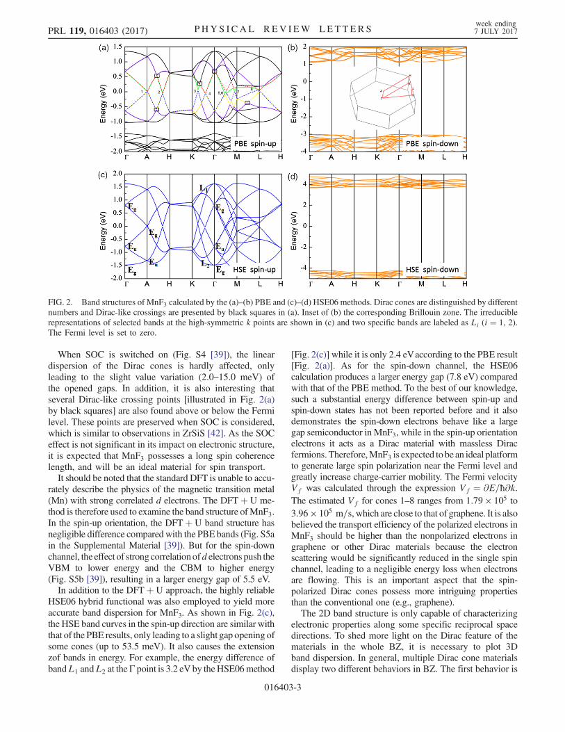
discontinuous Dirac cones; i.e., the number of cones iscountable and they are isolated in the BZ, e.g., the predictedP6=mmm boron sheet [43]. The second case is the con-tinuous Dirac cones, which means a high density of Diraccones exists and they form a ring of Dirac nodes [44] or aDirac loop as reported before. As a material with multiplecones, MnF3 is found to be different from both the above.From the 3D band plots in Fig. 3(a) and 3(b), we can clearlysee theMnF3 displays two rings ofDirac nodes in theM-K-Γplane of the BZ. Interestingly, if symmetry effect is consid-ered in this bulk material, it is expected to possess additionalDirac ring in the A-H-L plane. Such multiple Dirac ringmaterial is very rare and it differs from the known Diracmaterials such as graphene. If we compare the 3D plot with2D band dispersion in Fig. 2(a), we can find the Dirac conepair 3 and7 are responsible for ring 1, and cone 3 and5 are theorigins of ring 2. Furthermore, a ring of Dirac-like crossings[asmentioned in Fig. 2(a)] can also be found below the Fermilevel [black square in Fig. 3(a)], which indicates the highcarrier mobility of theMnF3 is not just confined to the Fermilevel, but also occurs above or below the Fermi level withinthe energy range of 0.75 eV. Such a unique multiple Diracring feature in MnF3 is expected to bring about morefascinating electronic properties and applications than otherDirac structures with the single cone or ring.To gainmore insight into the electronic properties ofMnF3
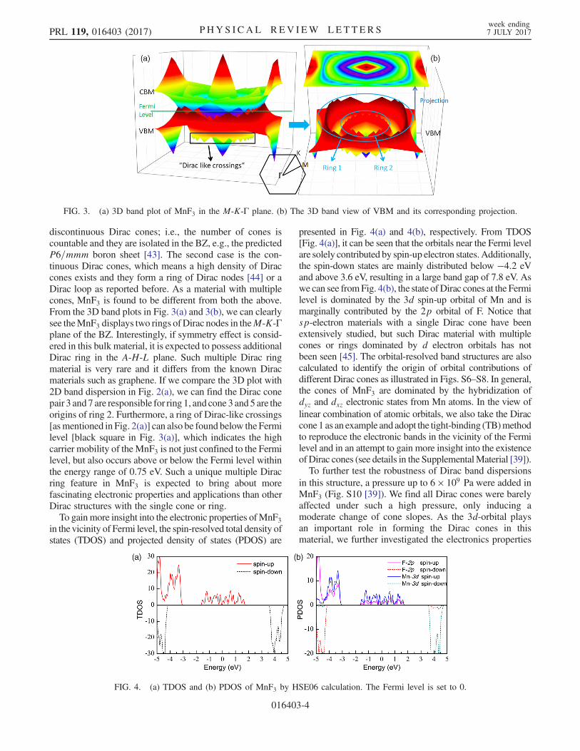
in the vicinity of Fermi level, the spin-resolved total density ofstates (TDOS) and projected density of states (PDOS) are
presented in Fig. 4(a) and 4(b), respectively. From TDOS[Fig. 4(a)], it can be seen that the orbitals near the Fermi levelare solely contributed by spin-up electron states.Additionally,the spin-down states are mainly distributed below −4.2 eVand above 3.6 eV, resulting in a large band gap of 7.8 eV. Aswe can see fromFig. 4(b), the state ofDirac cones at the Fermilevel is dominated by the 3d spin-up orbital of Mn and ismarginally contributed by the 2p orbital of F. Notice thatsp-electron materials with a single Dirac cone have beenextensively studied, but such Dirac material with multiplecones or rings dominated by d electron orbitals has notbeen seen [45]. The orbital-resolved band structures are alsocalculated to identify the origin of orbital contributions ofdifferent Dirac cones as illustrated in Figs. S6–S8. In general,the cones of MnF3 are dominated by the hybridization ofdyz and dxz electronic states from Mn atoms. In the view oflinear combination of atomic orbitals, we also take the Diraccone1 as an example and adopt the tight-binding (TB)methodto reproduce the electronic bands in the vicinity of the Fermilevel and in an attempt to gain more insight into the existenceof Dirac cones (see details in the SupplementalMaterial [39]).To further test the robustness of Dirac band dispersions
in this structure, a pressure up to 6 × 10⁹ Pa were added inMnF3 (Fig. S10 [39]). We find all Dirac cones were barelyaffected under such a high pressure, only inducing amoderate change of cone slopes. As the 3d-orbital playsan important role in forming the Dirac cones in thismaterial, we further investigated the electronics properties
FIG. 3. (a) 3D band plot of MnF3 in the M-K-Γ plane. (b) The 3D band view of VBM and its corresponding projection.
FIG. 4. (a) TDOS and (b) PDOS of MnF3 by HSE06 calculation. The Fermi level is set to 0.
PRL 119, 016403 (2017) P HY S I CA L R EV I EW LE T T ER Sweek ending7 JULY 2017
016403-4
of some other 3d-transition metal fluorides CoF3, CrF3, andFeF3 as shown in Fig. S11–S13. Large magnetic momentsof 3, 3, 5 μB per formula unit can be found in these threestructures, respectively. Interestingly, the spin-polarizedmultiple-Dirac cones are all seen, but they are shiftedupwards in energy with respect to the Fermi level.In conclusion, we report the first example of an exper-
imentally realized material which exhibits spin-polarizedmultiple Dirac cones or rings in the electronic structure.MnF3 bridges a gap between Dirac materials and spin-tronics and it exhibits many unique properties includingmultiple Dirac rings, large spin polarization, and highcarrier mobility. Furthermore, the properties in MnF3 areintrinsic and do not require any external conditions inexperiments such as electric field, pressure, doping, orelement substitution. The reported MnF3 structure meetsthe requirement of high-efficiency spintronics, and thespeed of spin-polarized electrons and holes in MnF3 shouldbe much faster than previously reported spintronics mate-rials such as spin gapless semiconductor PbPdO2 [22],Mn2CoAl [23], and diluted magnetic semiconductors. Thiswork is expected to enrich the diversity of spin-polarizedDirac materials and boost the development of spintronics.
The authors thank the grants of high-performance com-puter time from computing facility atQueenslandUniversityof Technology and Australian National Facility. A. D.greatly appreciates the Australian Research Council QEIIFellowship and financial support of the Australian ResearchCouncil under Discovery Project (DP130102420).
Y. J. and F. M. contributed equally to this work.
*Corresponding [email protected]
[1] C. Chappert, A. Fert, and F. N. Van Dau, Nat. Mater. 6, 813(2007).
[2] S. Wolf, D. Awschalom, R. Buhrman, J. Daughton, S. VonMolnar, M. Roukes, A. Y. Chtchelkanova, and D. Treger,Science 294, 1488 (2001).
[3] I. Žutić, J. Fabian, and S. D. Sarma, Rev. Mod. Phys. 76,323 (2004).
[4] D. D. Awschalom and M. E. Flatté, Nat. Phys. 3, 153(2007).
[5] K. Sato and H. Katayama-Yoshida, Semicond. Sci. Technol.17, 367 (2002).
[6] S. Crooker, M. Furis, X. Lou, C. Adelmann, D. Smith, C.Palmstrøm, and P. Crowell, Science 309, 2191 (2005).
[7] X. Jiang, R. Wang, R. M. Shelby, R. M. Macfarlane, S. R.Bank, J. S. Harris, and S. S. P. Parkin, Phys. Rev. Lett. 94,056601 (2005).
[8] R. Jansen, Nat. Mater. 11, 400 (2012).[9] W. Han, R. K. Kawakami, M. Gmitra, and J. Fabian, Nat.
Nanotechnol. 9, 794 (2014).[10] X. Li, X. Wu, and J. Yang, J. Am. Chem. Soc. 136, 11065
(2014).
[11] X. Li, X. Wu, and J. Yang, J. Am. Chem. Soc. 136, 5664(2014).
[12] X.-L. Wang, S. X. Dou, and C. Zhang, NPG Asia Mater. 2,31 (2010).
[13] Y. Li, D. West, H. Huang, J. Li, S. B. Zhang, and W. Duan,Phys. Rev. B 92, 201403 (2015).
[14] Y. Ma, Y. Dai, X. Li, Q. Sun, and B. Huang, Carbon 73, 382(2014).
[15] Y. Li, Z. Zhou, P. Shen, and Z. Chen, ACS Nano 3, 1952(2009).
[16] J. Guan, W. Chen, Y. Li, G. Yu, Z. Shi, X. Huang, C. Sun,and Z. Chen, Adv. Funct. Mater. 23, 1507 (2013).
[17] C. Felser, G. H. Fecher, and B. Balke, Angew. Chem. Int.Ed. 46, 668 (2007).
[18] X. Li and J. Yang, Natl. Sci. Rev. 3, 365 (2016).[19] X.-L. Wang, Natl. Sci. Rev. 4, 252 (2017).[20] A. Du, S. Sanvito, and S. C. Smith, Phys. Rev. Lett. 108,
197207 (2012).[21] F. Wu, C. Huang, H. Wu, C. Lee, K. Deng, E. Kan, and P.
Jena, Nano Lett. 15, 8277 (2015).[22] X. L. Wang, Phys. Rev. Lett. 100, 156404 (2008).[23] S. Ouardi, G. H. Fecher, C. Felser, and J. Kübler, Phys. Rev.
Lett. 110, 100401 (2013).[24] H. Ishizuka and Y. Motome, Phys. Rev. Lett. 109, 237207
(2012).[25] X. Zhang, A. Wang, and M. Zhao, Carbon 84, 1
(2015).[26] T. Cai, X. Li, F. Wang, S. Ju, J. Feng, and C.-D. Gong, Nano
Lett. 15, 6434 (2015).[27] J. He, X. Li, P. Lyu, and P. Nachtigall, Nanoscale 9, 2246
(2017).[28] Z. F. Wang, Z. Liu, and F. Liu, Phys. Rev. Lett. 110, 196801
(2013).[29] C. H. Lee, X. Zhang, and B. Guan, Sci. Rep. 5, 18008
(2015).[30] J. P. Perdew, K. Burke, and M. Ernzerhof, Phys. Rev. Lett.
77, 3865 (1996).[31] G. Kresse and J. Furthmüller, Phys. Rev. B 54, 11169
(1996).[32] G. Kresse and J. Furthmuller, Comput. Mater. Sci. 6, 15
(1996).[33] S. Grimme, J. Comput. Chem. 27, 1787 (2006).[34] V. I. Anisimov, J. Zaanen, and O. K. Andersen, Phys. Rev. B
44, 943 (1991).[35] J. Heyd, G. E. Scuseria, and M. Ernzerhof, J. Chem. Phys.
124, 219906 (2006).[36] P. V. Nhat, N. T. Cuong, P. K. Duy, and M. T. Nguyen,
Chem. Phys. 400, 185 (2012).[37] G. Müller Bernd and M. Serafin, Zeitschrift für Naturfor-
schung B 42, 1102 (1987).[38] Z. Mazej, J. Fluorine Chem. 114, 75 (2002).[39] See Supplemental Material at http://link.aps.org/
supplemental/10.1103/PhysRevLett.119.016403 for energycomparison of FM, AFM, and NM states and bandstructures calculated by PBEþ SOC, DFTþ U, and TBmethods as well as orbital-resolved band structures etc.,which includes Ref. [40].
[40] J. S. Lim, D. Saldana-Greco, and A. M. Rappe, Phys. Rev. B94, 165151 (2016).
PRL 119, 016403 (2017) P HY S I CA L R EV I EW LE T T ER Sweek ending7 JULY 2017
016403-5
[41] Y. D. Lensky, J. C. W. Song, P. Samutpraphoot, and L. S.Levitov, Phys. Rev. Lett. 114, 256601 (2015).
[42] L. M. Schoop et al., Nat. Commun. 7, 11696 (2016).[43] F. Ma, Y. Jiao, G. Gao, Y. Gu, A. Bilic, Z. Chen, and A. Du,
Nano Lett. 16, 3022 (2016).
[44] Y. Jiao, F. Ma, J. Bell, A. Bilic, and A. Du, Angew. Chem.128, 10448 (2016).
[45] K. Miyamoto, A. Kimura, K. Kuroda, T. Okuda, K.Shimada, H. Namatame, M. Taniguchi, and M. Donath,Phys. Rev. Lett. 108, 066808 (2012).
PRL 119, 016403 (2017) P HY S I CA L R EV I EW LE T T ER Sweek ending7 JULY 2017
016403-6