first hop redundancy protocols configuration guide, cisco...
TRANSCRIPT
First Hop Redundancy ProtocolsConfiguration Guide, Cisco IOS Release12.4
Americas HeadquartersCisco Systems, Inc.170 West Tasman DriveSan Jose, CA 95134-1706USAhttp://www.cisco.comTel: 408 526-4000 800 553-NETS (6387)Fax: 408 527-0883

THE SPECIFICATIONS AND INFORMATION REGARDING THE PRODUCTS IN THIS MANUAL ARE SUBJECT TO CHANGE WITHOUT NOTICE. ALL STATEMENTS,INFORMATION, AND RECOMMENDATIONS IN THIS MANUAL ARE BELIEVED TO BE ACCURATE BUT ARE PRESENTED WITHOUT WARRANTY OF ANY KIND,EXPRESS OR IMPLIED. USERS MUST TAKE FULL RESPONSIBILITY FOR THEIR APPLICATION OF ANY PRODUCTS.
THE SOFTWARE LICENSE AND LIMITED WARRANTY FOR THE ACCOMPANYING PRODUCT ARE SET FORTH IN THE INFORMATION PACKET THAT SHIPPEDWITH THE PRODUCT AND ARE INCORPORATED HEREIN BY THIS REFERENCE. IF YOU ARE UNABLE TO LOCATE THE SOFTWARE LICENSE OR LIMITEDWARRANTY, CONTACT YOUR CISCO REPRESENTATIVE FOR A COPY.
The Cisco implementation of TCP header compression is an adaptation of a program developed by the University of California, Berkeley (UCB) as part of UCB’s public domain versionof the UNIX operating system. All rights reserved. Copyright © 1981, Regents of the University of California.
NOTWITHSTANDING ANY OTHER WARRANTY HEREIN, ALL DOCUMENT FILES AND SOFTWARE OF THESE SUPPLIERS ARE PROVIDED “AS IS” WITH ALLFAULTS. CISCO AND THE ABOVE-NAMED SUPPLIERS DISCLAIM ALL WARRANTIES, EXPRESSED OR IMPLIED, INCLUDING, WITHOUT LIMITATION, THOSE OFMERCHANTABILITY, FITNESS FOR A PARTICULAR PURPOSE AND NONINFRINGEMENT OR ARISING FROM A COURSE OF DEALING, USAGE, OR TRADEPRACTICE.
IN NO EVENT SHALL CISCO OR ITS SUPPLIERS BE LIABLE FOR ANY INDIRECT, SPECIAL, CONSEQUENTIAL, OR INCIDENTAL DAMAGES, INCLUDING,WITHOUT LIMITATION, LOST PROFITS OR LOSS OR DAMAGE TO DATA ARISING OUT OF THE USE OR INABILITY TO USE THIS MANUAL, EVEN IF CISCO ORITS SUPPLIERS HAVE BEEN ADVISED OF THE POSSIBILITY OF SUCH DAMAGES.
Cisco and the Cisco logo are trademarks or registered trademarks of Cisco and/or its affiliates in the U.S. and other countries. To view a list of Cisco trademarks, go to this URL: www.cisco.com/go/trademarks. Third-party trademarks mentioned are the property of their respective owners. The use of the word partner does not imply a partnership relationshipbetween Cisco and any other company. (1110R)
Any Internet Protocol (IP) addresses and phone numbers used in this document are not intended to be actual addresses and phone numbers. Any examples, command display output,network topology diagrams, and other figures included in the document are shown for illustrative purposes only. Any use of actual IP addresses or phone numbers in illustrative contentis unintentional and coincidental.
© 2011 Cisco Systems, Inc. All rights reserved.
C O N T E N T S
Configuring GLBP 1
Finding Feature Information 1
Restrictions for GLBP 1
Prerequisites for GLBP 1
Information About GLBP 2
GLBP Overview 2
GLBP Active Virtual Gateway 2
GLBP Virtual MAC Address Assignment 3
GLBP Virtual Gateway Redundancy 4
GLBP Virtual Forwarder Redundancy 4
GLBP Gateway Priority 4
GLBP Gateway Weighting and Tracking 4
GLBP Client Cache 5
GLBP MD5 Authentication 6
ISSU--GLBP 6
GLBP SSO 6
GLBP Benefits 7
How to Configure GLBP 7
Enabling and Verifying GLBP 8
Customizing GLBP 9
Configuring GLBP MD5 Authentication Using a Key String 13
Configuring GLBP MD5 Authentication Using a Key Chain 14
Configuring GLBP Text Authentication 17
Configuring GLBP Weighting Values and Object Tracking 19
Troubleshooting GLBP 21
Configuration Examples for GLBP 23
Example: Customizing GLBP Configuration 23
Example: Configuring GLBP MD5 Authentication Using Key Strings 23
Example: Configuring GLBP MD5 Authentication Using Key Chains 24
First Hop Redundancy Protocols Configuration Guide, Cisco IOS Release 12.4 iii
Example: Configuring GLBP Text Authentication 24
Example: Configuring GLBP Weighting 24
Example: Enabling GLBP Configuration 24
Additional References 24
Feature Information for GLBP 26
Glossary 29
Configuring HSRP 31
Finding Feature Information 31
Restrictions for HSRP 31
Information About HSRP 32
HSRP Operation 33
HSRP Version 2 Design 34
HSRP Configuration Changes 35
HSRP Benefits 35
HSRP Groups and Group Attributes 36
HSRP Preemption 36
HSRP Priority and Preemption 36
How Object Tracking Affects the Priority of an HSRP Router 36
HSRP Addressing 37
HSRP Virtual MAC Addresses and BIA MAC Addresses 37
HSRP Timers 38
HSRP MAC Refresh Interval 38
HSRP Text Authentication 38
HSRP MD5 Authentication 38
HSRP Support for IPv6 39
HSRP Messages and States 39
HSRP Group Linking to IP Redundancy Clients 40
HSRP and ARP 40
HSRP Gratuitous ARP 40
HSRP Object Tracking 41
HSRP Group Shutdown 41
HSRP Support for ICMP Redirect Messages 41
ICMP Redirects to Active HSRP Routers 42
ICMP Redirects to Passive HSRP Routers 43
ICMP Redirects to Non-HSRP Routers 43
Contents
First Hop Redundancy Protocols Configuration Guide, Cisco IOS Release 12.4iv
Passive HSRP Router Advertisements 43
ICMP Redirects Not Sent 44
HSRP Support for MPLS VPNs 44
HSRP Multiple Group Optimization 45
HSRP--ISSU 45
SSO HSRP 45
SSO Dual-Route Processors and Cisco Nonstop Forwarding 46
HSRP and SSO Working Together 46
HSRP BFD Peering 46
HSRP MIB Traps 47
How to Configure HSRP 48
Enabling HSRP 48
Delaying the Initialization of HSRP on an Interface 50
Configuring HSRP Priority and Preemption 53
Configuring HSRP Object Tracking 54
Configuring HSRP MD5 Authentication Using a Key String 57
Configuring HSRP MD5 Authentication Using a Key Chain 59
Troubleshooting HSRP MD5 Authentication 62
Configuring HSRP Text Authentication 64
Configuring HSRP Timers 66
Configuring an HSRP MAC Refresh Interval 67
Configuring Multiple HSRP Groups for Load Balancing 68
Improving CPU and Network Performance with HSRP Multiple Group Optimization 70
Enabling HSRP Support for ICMP Redirect Messages 72
Configuring HSRP Virtual MAC Addresses or BIA MAC Addresses 74
Linking IP Redundancy Clients to HSRP Groups 75
Changing to HSRP Version 2 77
Enabling SSO Aware HSRP 79
Verifying SSO Aware HSRP 80
Enabling HSRP MIB Traps 81
Configuring BFD Session Parameters on the Interface 82
Configuring HSRP BFD Peering 83
Verifying HSRP BFD Peering 85
Configuring HSRP Gratuitous ARP 87
Configuration Examples for HSRP 88
Contents
First Hop Redundancy Protocols Configuration Guide, Cisco IOS Release 12.4 v
Example: Configuring HSRP Priority and Preemption 89
Example: Configuring HSRP Object Tracking 89
Example: Configuring HSRP Group Shutdown 90
Example: Configuring HSRP MD5 Authentication Using Key Strings 91
Example: Configuring HSRP MD5 Authentication Using Key Chains 91
Example: Configuring HSRP MD5 Authentication Using Key Strings and Key Chains 91
Example: Configuring HSRP Text Authentication 91
Example: Configuring Multiple HSRP Groups for Load Balancing 92
Example: Improving CPU and Network Performance with HSRP Multiple Group
Optimization 93
Example: Configuring HSRP Support for ICMP Redirect Messages 93
Example: Configuring HSRP Virtual MAC Addresses and BIA MAC Address 94
Example: Linking IP Redundancy Clients to HSRP Groups 94
Example: Configuring HSRP Version 2 95
Example: Enabling SSO-Aware HSRP 95
Example: Enabling HSRP MIB Traps 95
Example HSRP BFD Peering 96
Example: Configuring HSRP Gratuitous ARP 97
Additional References 97
Feature Information for HSRP 99
Glossary 103
Configuring IRDP 107
Finding Feature Information 107
Information About IRDP 107
IRDP Overview 107
How to Configure IRDP 108
Configuring IRDP 108
Configuration Examples for IRDP 110
Example: Configuring IRDP 110
Additional References 110
Feature Information for IRDP 111
Configuring VRRP 113
Finding Feature Information 113
Restrictions for VRRP 113
Information About VRRP 114
Contents
First Hop Redundancy Protocols Configuration Guide, Cisco IOS Release 12.4vi
VRRP Operation 114
VRRP Benefits 116
Multiple Virtual Router Support 117
VRRP Router Priority and Preemption 117
VRRP Advertisements 117
VRRP Object Tracking 118
How Object Tracking Affects the Priority of a VRRP Router 118
VRRP Authentication 118
In Service Software Upgrade--VRRP 119
VRRP Support for Stateful Switchover 119
How to Configure VRRP 119
Customizing VRRP 120
Enabling VRRP 122
Disabling a VRRP Group on an Interface 124
Configuring VRRP Object Tracking 125
Configuring VRRP MD5 Authentication Using a Key String 127
Configuring VRRP MD5 Authentication Using a Key Chain 129
Verifying the VRRP MD5 Authentication Configuration 132
Configuring VRRP Text Authentication 133
Enabling the Router to Send SNMP VRRP Notifications 135
Configuration Examples for VRRP 136
Example: Configuring VRRP 136
Example: VRRP Object Tracking 137
Example: VRRP Object Tracking Verification 137
Example: VRRP MD5 Authentication Configuration Using a Key String 138
Example: VRRP MD5 Authentication Configuration Using a Key Chain 138
Example: VRRP Text Authentication 138
Example: Disabling a VRRP Group on an Interface 138
Example: VRRP MIB Trap 138
Additional References 139
Feature Information for VRRP 140
Glossary 143
Contents
First Hop Redundancy Protocols Configuration Guide, Cisco IOS Release 12.4 vii

Contents
First Hop Redundancy Protocols Configuration Guide, Cisco IOS Release 12.4viii
Configuring GLBP
Gateway Load Balancing Protocol (GLBP) protects data traffic from a failed router or circuit, like HotStandby Router Protocol (HSRP) and Virtual Router Redundancy Protocol (VRRP), while allowingpacket load sharing between a group of redundant routers.
• Finding Feature Information, page 1• Restrictions for GLBP, page 1• Prerequisites for GLBP, page 1• Information About GLBP, page 2• How to Configure GLBP, page 7• Configuration Examples for GLBP, page 23• Additional References, page 24• Feature Information for GLBP, page 26• Glossary, page 29
Finding Feature InformationYour software release may not support all the features documented in this module. For the latest featureinformation and caveats, see the release notes for your platform and software release. To find informationabout the features documented in this module, and to see a list of the releases in which each feature issupported, see the Feature Information Table at the end of this document.
Use Cisco Feature Navigator to find information about platform support and Cisco software image support.To access Cisco Feature Navigator, go to www.cisco.com/go/cfn. An account on Cisco.com is not required.
Restrictions for GLBPEnhanced Object Tracking (EOT) is not stateful switchover (SSO)-aware and cannot be used with GLBP inSSO mode.
Prerequisites for GLBPBefore configuring GLBP, ensure that the routers can support multiple MAC addresses on the physicalinterfaces. For each GLBP forwarder to be configured, an additional MAC address is used.
First Hop Redundancy Protocols Configuration Guide, Cisco IOS Release 12.4 1
Information About GLBP• GLBP Overview, page 2
• GLBP Active Virtual Gateway, page 2
• GLBP Virtual MAC Address Assignment, page 3
• GLBP Virtual Gateway Redundancy, page 4
• GLBP Virtual Forwarder Redundancy, page 4
• GLBP Gateway Priority, page 4
• GLBP Gateway Weighting and Tracking, page 4
• GLBP Client Cache, page 5
• GLBP MD5 Authentication, page 6
• ISSU--GLBP, page 6
• GLBP SSO, page 6
• GLBP Benefits, page 7
GLBP OverviewGLBP provides automatic router backup for IP hosts configured with a single default gateway on an IEEE802.3 LAN. Multiple first-hop routers on the LAN combine to offer a single virtual first-hop IP routerwhile sharing the IP packet forwarding load. Other routers on the LAN may act as redundant GLBP routersthat will become active if any of the existing forwarding routers fail.
GLBP performs a similar function for the user as HSRP and VRRP. HSRP and VRRP allow multiplerouters to participate in a virtual router group configured with a virtual IP address. One member is electedto be the active router to forward packets sent to the virtual IP address for the group. The other routers inthe group are redundant until the active router fails. These standby routers have unused bandwidth that theprotocol is not using. Although multiple virtual router groups can be configured for the same set of routers,the hosts must be configured for different default gateways, which results in an extra administrative burden.The advantage of GLBP is that it additionally provides load balancing over multiple routers (gateways)using a single virtual IP address and multiple virtual MAC addresses. The forwarding load is shared amongall routers in a GLBP group rather than being handled by a single router while the other routers stand idle.Each host is configured with the same virtual IP address, and all routers in the virtual router groupparticipate in forwarding packets. GLBP members communicate between each other through hellomessages sent every 3 seconds to the multicast address 224.0.0.102, UDP port 3222 (source anddestination).
GLBP Active Virtual GatewayMembers of a GLBP group elect one gateway to be the active virtual gateway (AVG) for that group. Othergroup members provide backup for the AVG if the AVG becomes unavailable. The AVG assigns a virtualMAC address to each member of the GLBP group. Each gateway assumes responsibility for forwardingpackets sent to the virtual MAC address assigned to it by the AVG. These gateways are known as activevirtual forwarders (AVFs) for their virtual MAC address.
The AVG is also responsible for answering Address Resolution Protocol (ARP) requests for the virtual IPaddress. Load sharing is achieved by the AVG replying to the ARP requests with different virtual MACaddresses.
GLBP Overview Information About GLBP
First Hop Redundancy Protocols Configuration Guide, Cisco IOS Release 12.42
Prior to Cisco IOS Release 15.0(1)M1, 12.4(24)T2, 15.1(2)T, and later releases, when the no glbp load-balancing command is configured, the AVG always responds to ARP requests with the MAC address of itsAVF.
In Cisco IOS Release 15.0(1)M1, 12.4(24)T2, 15.1(2)T, and later releases, when the no glbp load-balancing command is configured, if the AVG does not have an AVF, it preferentially responds to ARPrequests with the MAC address of the first listening virtual forwarder (VF), which will causes traffic toroute via another gateway until that VF migrates back to being the current AVG.
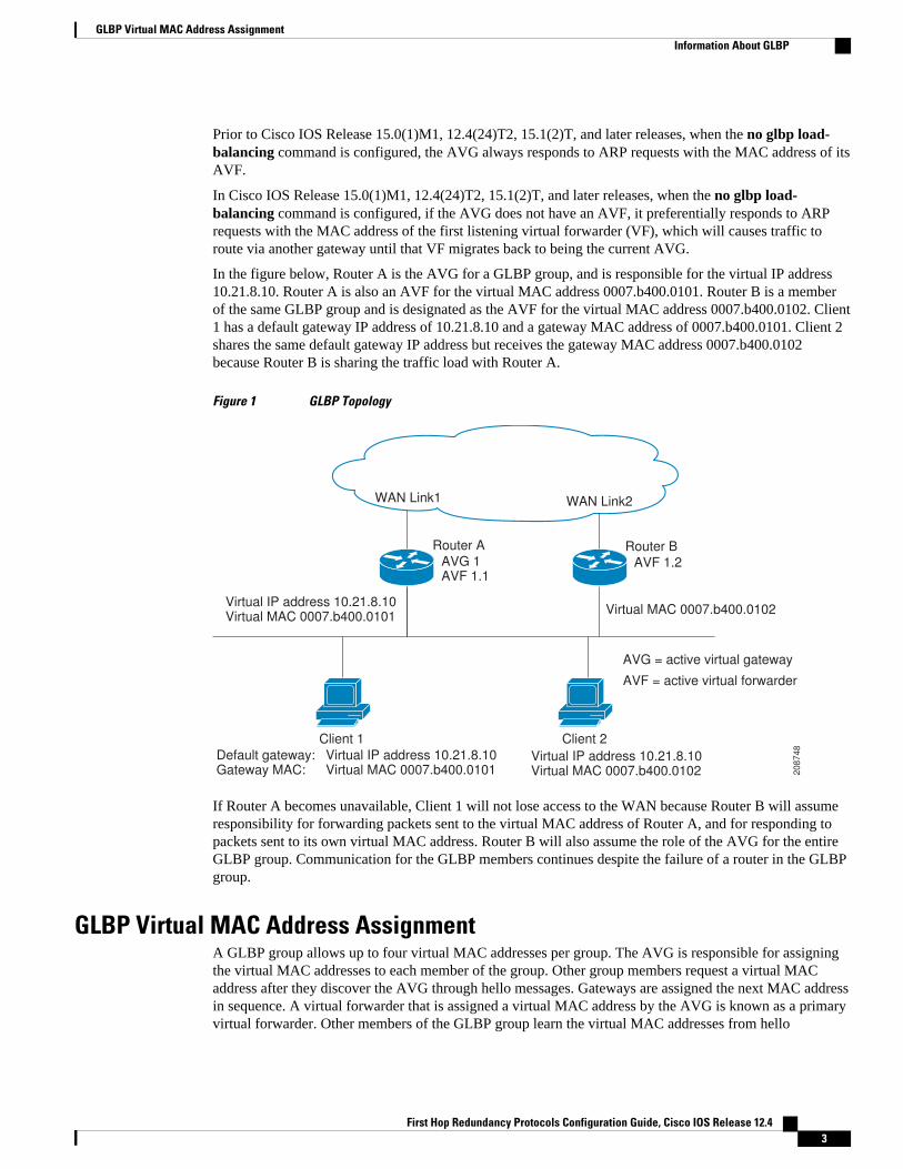
In the figure below, Router A is the AVG for a GLBP group, and is responsible for the virtual IP address10.21.8.10. Router A is also an AVF for the virtual MAC address 0007.b400.0101. Router B is a memberof the same GLBP group and is designated as the AVF for the virtual MAC address 0007.b400.0102. Client1 has a default gateway IP address of 10.21.8.10 and a gateway MAC address of 0007.b400.0101. Client 2shares the same default gateway IP address but receives the gateway MAC address 0007.b400.0102because Router B is sharing the traffic load with Router A.
Figure 1 GLBP Topology
Router A
AVG 1AVF 1.1
Router B
AVF 1.2
Virtual IP address 10.21.8.10Virtual MAC 0007.b400.0101
Virtual MAC 0007.b400.0102
Client 1
Default gateway: Virtual IP address 10.21.8.10Gateway MAC: Virtual MAC 0007.b400.0101
Virtual IP address 10.21.8.10Virtual MAC 0007.b400.0102
Client 2
AVG = active virtual gateway
AVF = active virtual forwarder
20
87
48
WAN Link1 WAN Link2
If Router A becomes unavailable, Client 1 will not lose access to the WAN because Router B will assumeresponsibility for forwarding packets sent to the virtual MAC address of Router A, and for responding topackets sent to its own virtual MAC address. Router B will also assume the role of the AVG for the entireGLBP group. Communication for the GLBP members continues despite the failure of a router in the GLBPgroup.
GLBP Virtual MAC Address AssignmentA GLBP group allows up to four virtual MAC addresses per group. The AVG is responsible for assigningthe virtual MAC addresses to each member of the group. Other group members request a virtual MACaddress after they discover the AVG through hello messages. Gateways are assigned the next MAC addressin sequence. A virtual forwarder that is assigned a virtual MAC address by the AVG is known as a primaryvirtual forwarder. Other members of the GLBP group learn the virtual MAC addresses from hello
GLBP Virtual MAC Address AssignmentInformation About GLBP
First Hop Redundancy Protocols Configuration Guide, Cisco IOS Release 12.4 3
messages. A virtual forwarder that has learned the virtual MAC address is referred to as a secondary virtualforwarder.
GLBP Virtual Gateway RedundancyGLBP operates virtual gateway redundancy in the same way as HSRP. One gateway is elected as the AVG,another gateway is elected as the standby virtual gateway, and the remaining gateways are placed in a listenstate.
If an AVG fails, the standby virtual gateway will assume responsibility for the virtual IP address. A newstandby virtual gateway is then elected from the gateways in the listen state.
GLBP Virtual Forwarder RedundancyVirtual forwarder redundancy is similar to virtual gateway redundancy with an AVF. If the AVF fails, oneof the secondary virtual forwarders in the listen state assumes responsibility for the virtual MAC address.
The new AVF is also a primary virtual forwarder for a different forwarder number. GLBP migrates hostsaway from the old forwarder number using two timers that start as soon as the gateway changes to theactive virtual forwarder state. GLBP uses the hello messages to communicate the current state of the timers.
The redirect time is the interval during which the AVG continues to redirect hosts to the old virtualforwarder MAC address. When the redirect time expires, the AVG stops using the old virtual forwarderMAC address in ARP replies, although the virtual forwarder will continue to forward packets that were sentto the old virtual forwarder MAC address.
The secondary holdtime is the interval during which the virtual forwarder is valid. When the secondaryholdtime expires, the virtual forwarder is removed from all gateways in the GLBP group. The expiredvirtual forwarder number becomes eligible for reassignment by the AVG.
GLBP Gateway PriorityGLBP gateway priority determines the role that each GLBP gateway plays and what happens if the AVGfails.
Priority also determines if a GLBP router functions as a backup virtual gateway and the order ofascendancy to becoming an AVG if the current AVG fails. You can configure the priority of each backupvirtual gateway with a value of 1 through 255 using the glbp priority command.
In the "GLBP Topology" figure, if Router A—the AVG in a LAN topology—fails, an election processtakes place to determine which backup virtual gateway should take over. In this example, Router B is theonly other member in the group so it will automatically become the new AVG. If another router existed inthe same GLBP group with a higher priority, then the router with the higher priority would be elected. Ifboth routers have the same priority, the backup virtual gateway with the higher IP address would be electedto become the active virtual gateway.
By default, the GLBP virtual gateway preemptive scheme is disabled. A backup virtual gateway canbecome the AVG only if the current AVG fails, regardless of the priorities assigned to the virtual gateways.You can enable the GLBP virtual gateway preemptive scheme using the glbp preempt command.Preemption allows a backup virtual gateway to become the AVG, if the backup virtual gateway is assigneda higher priority than the current AVG.
GLBP Gateway Weighting and TrackingGLBP uses a weighting scheme to determine the forwarding capacity of each router in the GLBP group.The weighting assigned to a router in the GLBP group can be used to determine whether it will forward
GLBP Virtual Gateway Redundancy Information About GLBP
First Hop Redundancy Protocols Configuration Guide, Cisco IOS Release 12.44
packets and, if so, the proportion of hosts in the LAN for which it will forward packets. Thresholds can beset to disable forwarding when the weighting for a GLBP group falls below a certain value, and when itrises above another threshold, forwarding is automatically reenabled.
The GLBP group weighting can be automatically adjusted by tracking the state of an interface within therouter. If a tracked interface goes down, the GLBP group weighting is reduced by a specified value.Different interfaces can be tracked to decrement the GLBP weighting by varying amounts.
By default, the GLBP virtual forwarder preemptive scheme is enabled with a delay of 30 seconds. Abackup virtual forwarder can become the AVF if the current AVF weighting falls below the low weightingthreshold for 30 seconds. You can disable the GLBP forwarder preemptive scheme using the no glbpforwarder preempt command or change the delay using the glbp forwarder preempt delay minimumcommand.
GLBP Client CacheThe GLBP client cache contains information about network hosts that are using a GLBP group as thedefault gateway.
When an IPv4 Address Resolution Protocol (ARP) request or an IPv6 Neighbor Discovery (ND) request fora GLBP virtual IP address is received from a network host by a GLBP group’s active virtual gateway(AVG), a new entry is created in the GLBP client cache. The cache entry contains information about thehost that sent the ARP or ND request and which forwarder the AVG has assigned to it.
The GLBP client cache stores the MAC address of each host that is using a particular GLBP group, thenumber of the GLBP forwarder that each network host has been assigned to and the total number ofnetwork hosts currently assigned to each forwarder in a GLBP group. The GLBP client cache also storesthe protocol address used by each network host and the time elapsed since the host-to-forwarder assignmentwas last updated.
The GLBP client cache can store information on up to 2000 network hosts for a GLBP group. The expectednormal maximum configuration is 1000 network hosts. You can configure a lower maximum number ofnetwork hosts that will be cached for each GLBP group independently based on the number of networkhosts that are using each GLBP group by using the glbp client-cache maximum command. This commandenables you to limit the amount of memory used by the cache per GLBP group. If the GLBP client cachehas reached the maximum configured number of clients and a new client is added, the least recentlyupdated client entry will be discarded. Reaching this condition indicates that the configured maximum limitis too small.
The amount of memory that is used by the GLBP client cache depends on the number of network hostsusing GLBP groups for which the client cache is enabled. For each host at least 20 bytes is required, withan additional 3200 bytes per GLBP group.
You can display the contents of the GLBP client cache using the show glbp detail command on the routerthat is currently the AVG for a GLBP group. If you issue the show glbp detail command on any otherrouter in a GLBP group, you will be directed to reissue the command on the AVG to view client cacheinformation. The show glbp detail command also displays statistics about the GLBP client cache usageand the distribution of clients among forwarders. These statistics are accurate as long as the cache timeoutand client limit parameters have been set appropriately. Appropriate values would be where the number ofend hosts on the network does not exceed the configured limit and where the maximum end host ARPcache timeout does not exceed the configured GLBP client cache timeout.
You can enable or disable the GLBP client cache independently for each GLBP group by using the glbpclient-cache command. The GLBP client cache is disabled by default. There is no limit on the number ofgroups for which the GLBP client cache can be enabled.
GLBP Client CacheInformation About GLBP
First Hop Redundancy Protocols Configuration Guide, Cisco IOS Release 12.4 5
You can configure GLBP cache entries to time out after a specified time by using the timeout keywordoption with the glbp client-cache maximum command.
GLBP MD5 AuthenticationGLBP MD5 authentication uses the industry-standard MD5 algorithm for improved reliability and security.MD5 authentication provides greater security than the alternative plain text authentication scheme andprotects against spoofing software.
MD5 authentication allows each GLBP group member to use a secret key to generate a keyed MD5 hashthat is part of the outgoing packet. A keyed hash of an incoming packet is generated and, if the hash withinthe incoming packet does not match the generated hash, the packet is ignored.
The key for the MD5 hash can either be given directly in the configuration using a key string or suppliedindirectly through a key chain. The key string cannot exceed 100 characters in length.
A router will ignore incoming GLBP packets from routers that do not have the same authenticationconfiguration for a GLBP group. GLBP has three authentication schemes:
• No authentication• Plain text authentication• MD5 authentication
GLBP packets will be rejected in any of the following cases:
• The authentication schemes differ on the router and in the incoming packet.• MD5 digests differ on the router and in the incoming packet.• Text authentication strings differ on the router and in the incoming packet.
ISSU--GLBPGLBP supports In Service Software Upgrade (ISSU). In Service Software Upgrade (ISSU) allows a high-availability (HA) system to run in Stateful Switchover (SSO) mode even when different versions of CiscoIOS software are running on the active and standby Route Processors (RPs) or line cards.
ISSU provides the ability to upgrade or downgrade from one supported Cisco IOS release to another whilecontinuing to forward packets and maintain sessions, thereby reducing planned outage time. The ability toupgrade or downgrade is achieved by running different software versions on the active RP and standby RPfor a short period of time to maintain state information between RPs. This feature allows the system toswitch over to a secondary RP running upgraded (or downgraded) software and continue forwardingpackets without session loss and with minimal or no packet loss. This feature is enabled by default.
For detailed information about ISSU, see the Cisco IOS In Service Software Upgrade Process in the CiscoIOS High Availability Configuration Guide
For detailed information about ISSU on the 7600 series routers, see the ISSU and eFSU on Cisco 7600Series Routers document at the following URL:
http://www.cisco.com/en/US/docs/routers/7600/ios/12.2SR/configuration/guide/efsuovrw.html
GLBP SSOWith the introduction of the GLBP SSO feature, GLBP is stateful switchover (SSO) aware. GLBP candetect when a router is failing over to the secondary router processor (RP) and continue in its current groupstate.
SSO functions in networking devices (usually edge devices) that support dua RPs. SSO provides RPredundancy by establishing one of the RPs as the active processor and the other RP as the standby
GLBP MD5 Authentication Information About GLBP
First Hop Redundancy Protocols Configuration Guide, Cisco IOS Release 12.46
processor. SSO also synchronizes critical state information between the RPs so that network stateinformation is dynamically maintained between RPs.
Without SSO-awareness, if GLBP is deployed on a router with redundant RPs, a switchover of rolesbetween the active RP and the standby RP results in the router relinquishing its activity as a GLBP groupmember and then rejoining the group as if it had been reloaded. The GLBP SSO feature enables GLBP tocontinue its activities as a group member during a switchover. GLBP state information between redundantRPs is maintained so that the standby RP can continue the router’s activities within the GLBP during andafter a switchover.
This feature is enabled by default. To disable this feature, use the no glbp sso command in globalconfiguration mode.
For more information, see the Stateful Swithover document in the Cisco IOS High AvailabilityConfiguration Guide.
GLBP Benefits
Load Sharing
You can configure GLBP in such a way that traffic from LAN clients can be shared by multiple routers,thereby sharing the traffic load more equitably among available routers.
Multiple Virtual Routers
GLBP supports up to 1024 virtual routers (GLBP groups) on each physical interface of a router and up tofour virtual forwarders per group.
Preemption
The redundancy scheme of GLBP enables you to preempt an active virtual gateway with a higher prioritybackup virtual gateway that has become available. Forwarder preemption works in a similar way, exceptthat forwarder preemption uses weighting instead of priority and is enabled by default.
Authentication
GLBP supports the industry-standard message digest 5 (MD5) algorithm for improved reliability, security,and protection against GLBP-spoofing software. A router within a GLBP group with a differentauthentication string than other routers will be ignored by other group members. You can alternatively usea simple text password authentication scheme between GLBP group members to detect configurationerrors.
How to Configure GLBP• Enabling and Verifying GLBP, page 8
• Customizing GLBP, page 9
• Configuring GLBP MD5 Authentication Using a Key String, page 13
• Configuring GLBP MD5 Authentication Using a Key Chain, page 14
• Configuring GLBP Text Authentication, page 17
• Configuring GLBP Weighting Values and Object Tracking, page 19
• Troubleshooting GLBP, page 21
GLBP BenefitsHow to Configure GLBP
First Hop Redundancy Protocols Configuration Guide, Cisco IOS Release 12.4 7
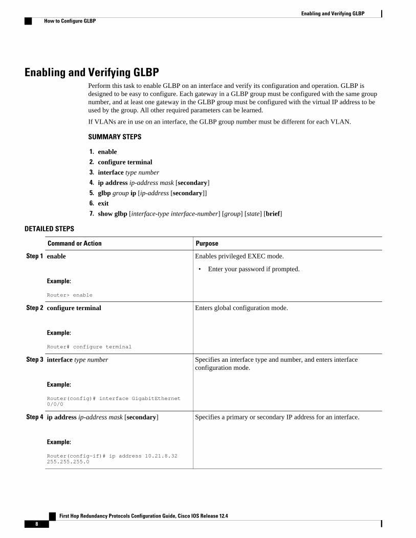
Enabling and Verifying GLBPPerform this task to enable GLBP on an interface and verify its configuration and operation. GLBP isdesigned to be easy to configure. Each gateway in a GLBP group must be configured with the same groupnumber, and at least one gateway in the GLBP group must be configured with the virtual IP address to beused by the group. All other required parameters can be learned.
If VLANs are in use on an interface, the GLBP group number must be different for each VLAN.
SUMMARY STEPS
1. enable
2. configure terminal
3. interface type number
4. ip address ip-address mask [secondary]
5. glbp group ip [ip-address [secondary]]
6. exit
7. show glbp [interface-type interface-number] [group] [state] [brief]
DETAILED STEPS
Command or Action Purpose
Step 1 enable
Example:
Router> enable
Enables privileged EXEC mode.
• Enter your password if prompted.
Step 2 configure terminal
Example:
Router# configure terminal
Enters global configuration mode.
Step 3 interface type number
Example:
Router(config)# interface GigabitEthernet 0/0/0
Specifies an interface type and number, and enters interfaceconfiguration mode.
Step 4 ip address ip-address mask [secondary]
Example:
Router(config-if)# ip address 10.21.8.32 255.255.255.0
Specifies a primary or secondary IP address for an interface.
Enabling and Verifying GLBP How to Configure GLBP
First Hop Redundancy Protocols Configuration Guide, Cisco IOS Release 12.48
Command or Action Purpose
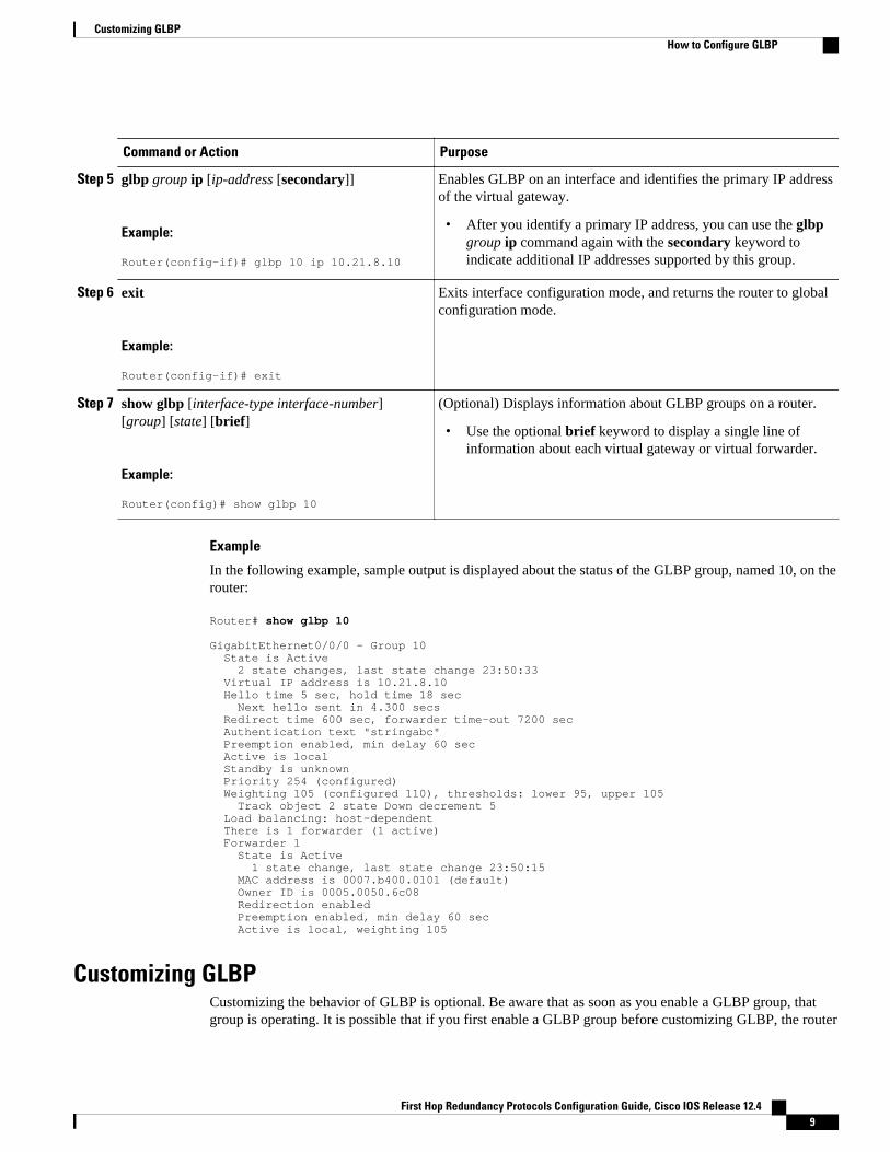
Step 5 glbp group ip [ip-address [secondary]]
Example:
Router(config-if)# glbp 10 ip 10.21.8.10
Enables GLBP on an interface and identifies the primary IP addressof the virtual gateway.
• After you identify a primary IP address, you can use the glbpgroup ip command again with the secondary keyword toindicate additional IP addresses supported by this group.
Step 6 exit
Example:
Router(config-if)# exit
Exits interface configuration mode, and returns the router to globalconfiguration mode.
Step 7 show glbp [interface-type interface-number][group] [state] [brief]
Example:
Router(config)# show glbp 10
(Optional) Displays information about GLBP groups on a router.
• Use the optional brief keyword to display a single line ofinformation about each virtual gateway or virtual forwarder.
Example
In the following example, sample output is displayed about the status of the GLBP group, named 10, on therouter:
Router# show glbp 10
GigabitEthernet0/0/0 - Group 10 State is Active 2 state changes, last state change 23:50:33 Virtual IP address is 10.21.8.10 Hello time 5 sec, hold time 18 sec Next hello sent in 4.300 secs Redirect time 600 sec, forwarder time-out 7200 sec Authentication text "stringabc" Preemption enabled, min delay 60 sec Active is local Standby is unknown Priority 254 (configured) Weighting 105 (configured 110), thresholds: lower 95, upper 105 Track object 2 state Down decrement 5 Load balancing: host-dependent There is 1 forwarder (1 active) Forwarder 1 State is Active 1 state change, last state change 23:50:15 MAC address is 0007.b400.0101 (default) Owner ID is 0005.0050.6c08 Redirection enabled Preemption enabled, min delay 60 sec Active is local, weighting 105
Customizing GLBPCustomizing the behavior of GLBP is optional. Be aware that as soon as you enable a GLBP group, thatgroup is operating. It is possible that if you first enable a GLBP group before customizing GLBP, the router
Customizing GLBPHow to Configure GLBP
First Hop Redundancy Protocols Configuration Guide, Cisco IOS Release 12.4 9
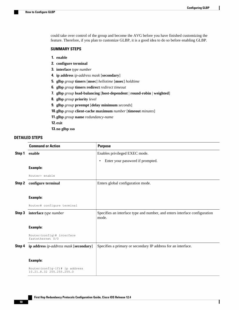
could take over control of the group and become the AVG before you have finished customizing thefeature. Therefore, if you plan to customize GLBP, it is a good idea to do so before enabling GLBP.
SUMMARY STEPS
1. enable
2. configure terminal
3. interface type number
4. ip address ip-address mask [secondary]
5. glbp group timers [msec] hellotime [msec] holdtime
6. glbp group timers redirect redirect timeout
7. glbp group load-balancing [host-dependent | round-robin | weighted]
8. glbp group priority level
9. glbp group preempt [delay minimum seconds]
10. glbp group client-cache maximum number [timeout minutes]
11. glbp group name redundancy-name
12. exit
13. no glbp sso
DETAILED STEPS
Command or Action Purpose
Step 1 enable
Example:
Router> enable
Enables privileged EXEC mode.
• Enter your password if prompted.
Step 2 configure terminal
Example:
Router# configure terminal
Enters global configuration mode.
Step 3 interface type number
Example:
Router(config)# interface fastethernet 0/0
Specifies an interface type and number, and enters interface configurationmode.
Step 4 ip address ip-address mask [secondary]
Example:
Router(config-if)# ip address 10.21.8.32 255.255.255.0
Specifies a primary or secondary IP address for an interface.
Configuring GLBP How to Configure GLBP
First Hop Redundancy Protocols Configuration Guide, Cisco IOS Release 12.410
Command or Action Purpose
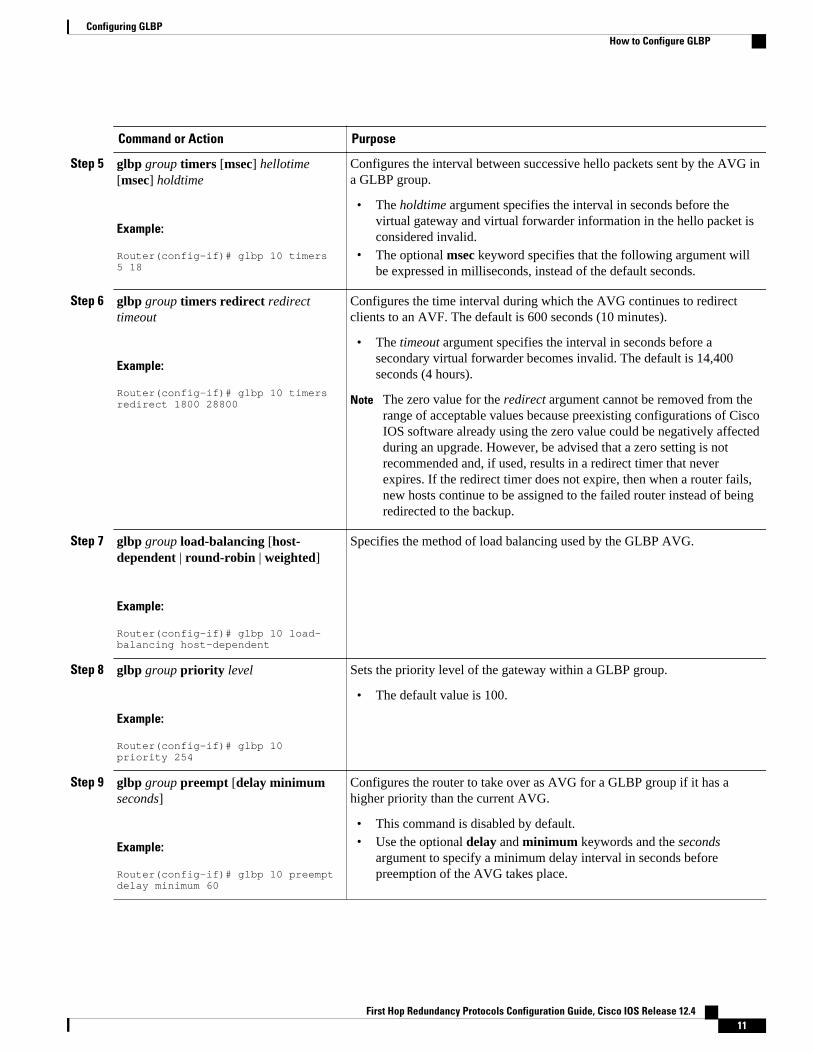
Step 5 glbp group timers [msec] hellotime[msec] holdtime
Example:
Router(config-if)# glbp 10 timers 5 18
Configures the interval between successive hello packets sent by the AVG ina GLBP group.
• The holdtime argument specifies the interval in seconds before thevirtual gateway and virtual forwarder information in the hello packet isconsidered invalid.
• The optional msec keyword specifies that the following argument willbe expressed in milliseconds, instead of the default seconds.
Step 6 glbp group timers redirect redirecttimeout
Example:
Router(config-if)# glbp 10 timers redirect 1800 28800
Configures the time interval during which the AVG continues to redirectclients to an AVF. The default is 600 seconds (10 minutes).
• The timeout argument specifies the interval in seconds before asecondary virtual forwarder becomes invalid. The default is 14,400seconds (4 hours).
Note The zero value for the redirect argument cannot be removed from therange of acceptable values because preexisting configurations of CiscoIOS software already using the zero value could be negatively affectedduring an upgrade. However, be advised that a zero setting is notrecommended and, if used, results in a redirect timer that neverexpires. If the redirect timer does not expire, then when a router fails,new hosts continue to be assigned to the failed router instead of beingredirected to the backup.
Step 7 glbp group load-balancing [host-dependent | round-robin | weighted]
Example:
Router(config-if)# glbp 10 load-balancing host-dependent
Specifies the method of load balancing used by the GLBP AVG.
Step 8 glbp group priority level
Example:
Router(config-if)# glbp 10 priority 254
Sets the priority level of the gateway within a GLBP group.
• The default value is 100.
Step 9 glbp group preempt [delay minimumseconds]
Example:
Router(config-if)# glbp 10 preempt delay minimum 60
Configures the router to take over as AVG for a GLBP group if it has ahigher priority than the current AVG.
• This command is disabled by default.• Use the optional delay and minimum keywords and the seconds
argument to specify a minimum delay interval in seconds beforepreemption of the AVG takes place.
Configuring GLBPHow to Configure GLBP
First Hop Redundancy Protocols Configuration Guide, Cisco IOS Release 12.4 11
Command or Action Purpose
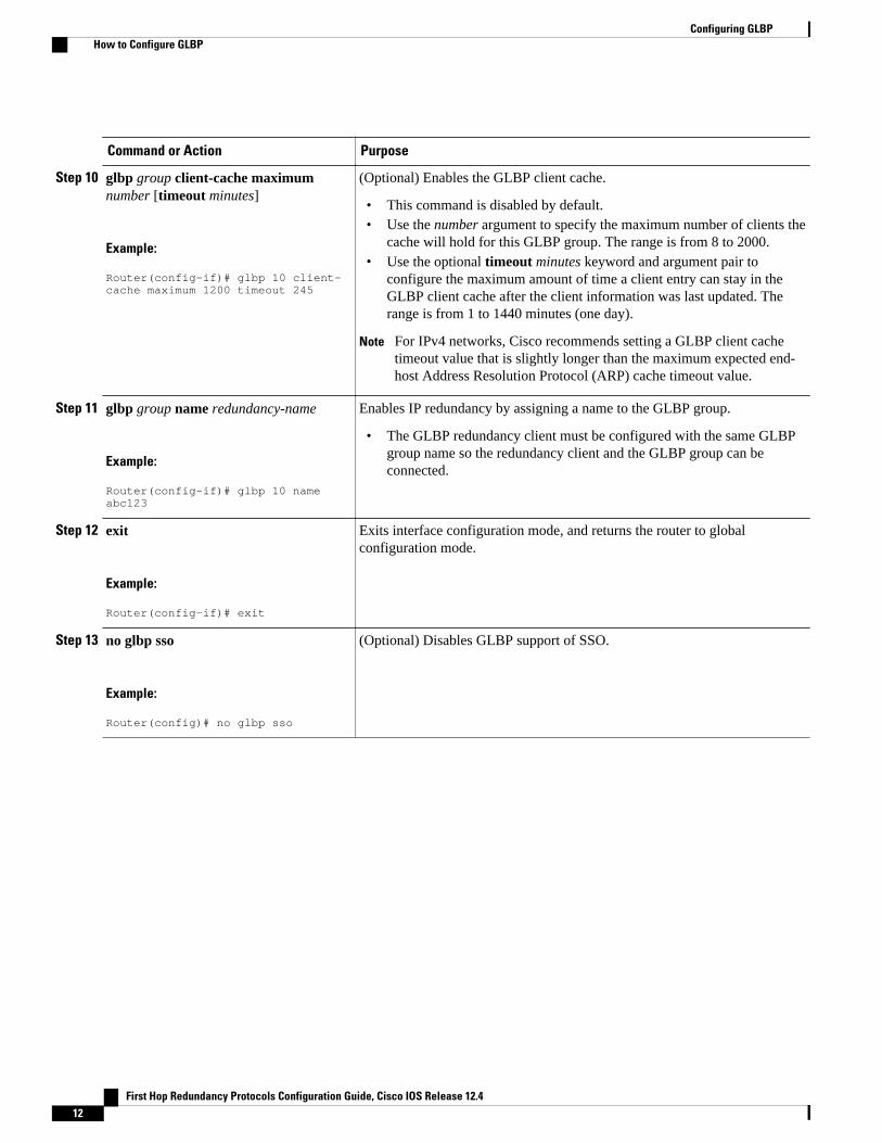
Step 10 glbp group client-cache maximumnumber [timeout minutes]
Example:
Router(config-if)# glbp 10 client-cache maximum 1200 timeout 245
(Optional) Enables the GLBP client cache.
• This command is disabled by default.• Use the number argument to specify the maximum number of clients the
cache will hold for this GLBP group. The range is from 8 to 2000.• Use the optional timeout minutes keyword and argument pair to
configure the maximum amount of time a client entry can stay in theGLBP client cache after the client information was last updated. Therange is from 1 to 1440 minutes (one day).
Note For IPv4 networks, Cisco recommends setting a GLBP client cachetimeout value that is slightly longer than the maximum expected end-host Address Resolution Protocol (ARP) cache timeout value.
Step 11 glbp group name redundancy-name
Example:
Router(config-if)# glbp 10 name abc123
Enables IP redundancy by assigning a name to the GLBP group.
• The GLBP redundancy client must be configured with the same GLBPgroup name so the redundancy client and the GLBP group can beconnected.
Step 12 exit
Example:
Router(config-if)# exit
Exits interface configuration mode, and returns the router to globalconfiguration mode.
Step 13 no glbp sso
Example:
Router(config)# no glbp sso
(Optional) Disables GLBP support of SSO.
Configuring GLBP How to Configure GLBP
First Hop Redundancy Protocols Configuration Guide, Cisco IOS Release 12.412
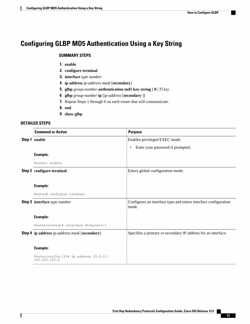
Configuring GLBP MD5 Authentication Using a Key String
SUMMARY STEPS
1. enable
2. configure terminal
3. interface type number
4. ip address ip-address mask [secondary]
5. glbp group-number authentication md5 key-string [ 0 | 7] key
6. glbp group-number ip [ip-address [secondary ]]
7. Repeat Steps 1 through 6 on each router that will communicate.
8. end
9. show glbp
DETAILED STEPS
Command or Action Purpose
Step 1 enable
Example:
Router> enable
Enables privileged EXEC mode.
• Enter your password if prompted.
Step 2 configure terminal
Example:
Router# configure terminal
Enters global configuration mode.
Step 3 interface type number
Example:
Router(config)# interface Ethernet0/1
Configures an interface type and enters interface configurationmode.
Step 4 ip address ip-address mask [secondary]
Example:
Router(config-if)# ip address 10.0.0.1 255.255.255.0
Specifies a primary or secondary IP address for an interface.
Configuring GLBP MD5 Authentication Using a Key StringHow to Configure GLBP
First Hop Redundancy Protocols Configuration Guide, Cisco IOS Release 12.4 13
Command or Action Purpose
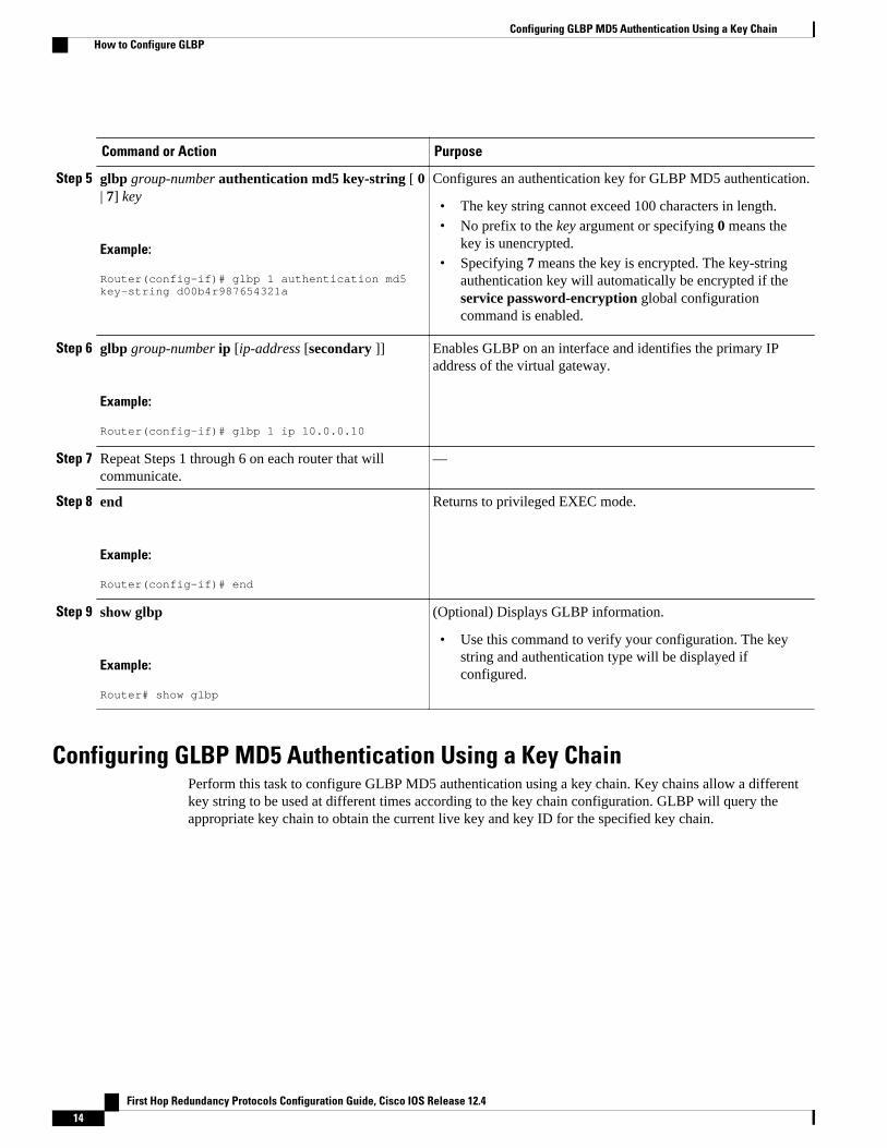
Step 5 glbp group-number authentication md5 key-string [ 0| 7] key
Example:
Router(config-if)# glbp 1 authentication md5 key-string d00b4r987654321a
Configures an authentication key for GLBP MD5 authentication.
• The key string cannot exceed 100 characters in length.• No prefix to the key argument or specifying 0 means the
key is unencrypted.• Specifying 7 means the key is encrypted. The key-string
authentication key will automatically be encrypted if theservice password-encryption global configurationcommand is enabled.
Step 6 glbp group-number ip [ip-address [secondary ]]
Example:
Router(config-if)# glbp 1 ip 10.0.0.10
Enables GLBP on an interface and identifies the primary IPaddress of the virtual gateway.
Step 7 Repeat Steps 1 through 6 on each router that willcommunicate.
—
Step 8 end
Example:
Router(config-if)# end
Returns to privileged EXEC mode.
Step 9 show glbp
Example:
Router# show glbp
(Optional) Displays GLBP information.
• Use this command to verify your configuration. The keystring and authentication type will be displayed ifconfigured.
Configuring GLBP MD5 Authentication Using a Key ChainPerform this task to configure GLBP MD5 authentication using a key chain. Key chains allow a differentkey string to be used at different times according to the key chain configuration. GLBP will query theappropriate key chain to obtain the current live key and key ID for the specified key chain.
Configuring GLBP MD5 Authentication Using a Key Chain How to Configure GLBP
First Hop Redundancy Protocols Configuration Guide, Cisco IOS Release 12.414
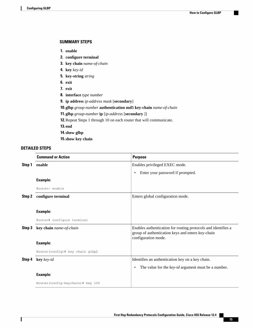
SUMMARY STEPS
1. enable
2. configure terminal
3. key chain name-of-chain
4. key key-id
5. key-string string
6. exit
7. exit
8. interface type number
9. ip address ip-address mask [secondary]
10. glbp group-number authentication md5 key-chain name-of-chain
11. glbp group-number ip [ip-address [secondary ]]
12. Repeat Steps 1 through 10 on each router that will communicate.
13. end
14. show glbp
15. show key chain
DETAILED STEPS
Command or Action Purpose
Step 1 enable
Example:
Router> enable
Enables privileged EXEC mode.
• Enter your password if prompted.
Step 2 configure terminal
Example:
Router# configure terminal
Enters global configuration mode.
Step 3 key chain name-of-chain
Example:
Router(config)# key chain glbp2
Enables authentication for routing protocols and identifies agroup of authentication keys and enters key-chainconfiguration mode.
Step 4 key key-id
Example:
Router(config-keychain)# key 100
Identifies an authentication key on a key chain.
• The value for the key-id argument must be a number.
Configuring GLBPHow to Configure GLBP
First Hop Redundancy Protocols Configuration Guide, Cisco IOS Release 12.4 15
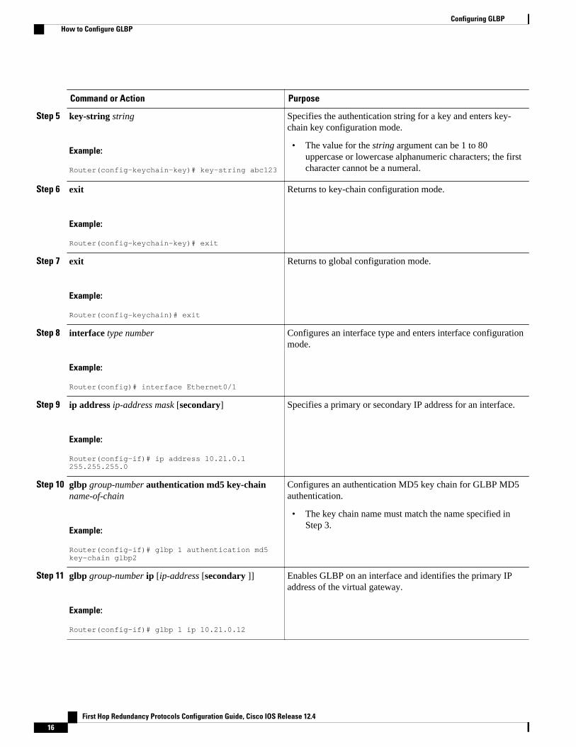
Command or Action Purpose
Step 5 key-string string
Example:
Router(config-keychain-key)# key-string abc123
Specifies the authentication string for a key and enters key-chain key configuration mode.
• The value for the string argument can be 1 to 80uppercase or lowercase alphanumeric characters; the firstcharacter cannot be a numeral.
Step 6 exit
Example:
Router(config-keychain-key)# exit
Returns to key-chain configuration mode.
Step 7 exit
Example:
Router(config-keychain)# exit
Returns to global configuration mode.
Step 8 interface type number
Example:
Router(config)# interface Ethernet0/1
Configures an interface type and enters interface configurationmode.
Step 9 ip address ip-address mask [secondary]
Example:
Router(config-if)# ip address 10.21.0.1 255.255.255.0
Specifies a primary or secondary IP address for an interface.
Step 10 glbp group-number authentication md5 key-chainname-of-chain
Example:
Router(config-if)# glbp 1 authentication md5 key-chain glbp2
Configures an authentication MD5 key chain for GLBP MD5authentication.
• The key chain name must match the name specified inStep 3.
Step 11 glbp group-number ip [ip-address [secondary ]]
Example:
Router(config-if)# glbp 1 ip 10.21.0.12
Enables GLBP on an interface and identifies the primary IPaddress of the virtual gateway.
Configuring GLBP How to Configure GLBP
First Hop Redundancy Protocols Configuration Guide, Cisco IOS Release 12.416
Command or Action Purpose
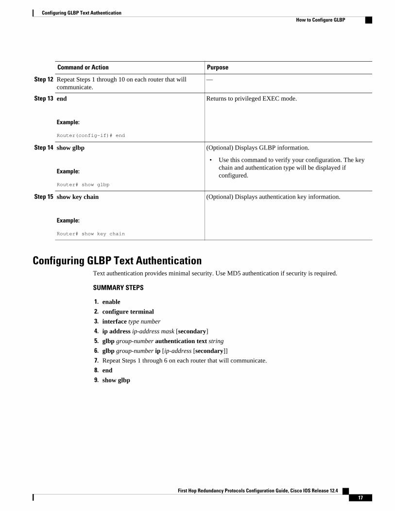
Step 12 Repeat Steps 1 through 10 on each router that willcommunicate.
—
Step 13 end
Example:
Router(config-if)# end
Returns to privileged EXEC mode.
Step 14 show glbp
Example:
Router# show glbp
(Optional) Displays GLBP information.
• Use this command to verify your configuration. The keychain and authentication type will be displayed ifconfigured.
Step 15 show key chain
Example:
Router# show key chain
(Optional) Displays authentication key information.
Configuring GLBP Text AuthenticationText authentication provides minimal security. Use MD5 authentication if security is required.
SUMMARY STEPS
1. enable
2. configure terminal
3. interface type number
4. ip address ip-address mask [secondary]
5. glbp group-number authentication text string
6. glbp group-number ip [ip-address [secondary]]
7. Repeat Steps 1 through 6 on each router that will communicate.
8. end
9. show glbp
Configuring GLBP Text AuthenticationHow to Configure GLBP
First Hop Redundancy Protocols Configuration Guide, Cisco IOS Release 12.4 17
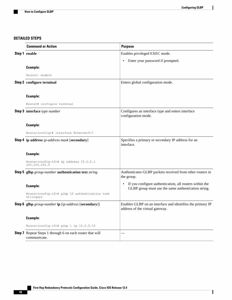
DETAILED STEPS
Command or Action Purpose
Step 1 enable
Example:
Router> enable
Enables privileged EXEC mode.
• Enter your password if prompted.
Step 2 configure terminal
Example:
Router# configure terminal
Enters global configuration mode.
Step 3 interface type number
Example:
Router(config)# interface Ethernet0/1
Configures an interface type and enters interfaceconfiguration mode.
Step 4 ip address ip-address mask [secondary]
Example:
Router(config-if)# ip address 10.0.0.1 255.255.255.0
Specifies a primary or secondary IP address for aninterface.
Step 5 glbp group-number authentication text string
Example:
Router(config-if)# glbp 10 authentication text stringxyz
Authenticates GLBP packets received from other routers inthe group.
• If you configure authentication, all routers within theGLBP group must use the same authentication string.
Step 6 glbp group-number ip [ip-address [secondary]]
Example:
Router(config-if)# glbp 1 ip 10.0.0.10
Enables GLBP on an interface and identifies the primary IPaddress of the virtual gateway.
Step 7 Repeat Steps 1 through 6 on each router that willcommunicate.
—
Configuring GLBP How to Configure GLBP
First Hop Redundancy Protocols Configuration Guide, Cisco IOS Release 12.418
Command or Action Purpose
Step 8 end
Example:
Router(config-if)# end
Returns to privileged EXEC mode.
Step 9 show glbp
Example:
Router# show glbp
(Optional) Displays GLBP information.
• Use this command to verify your configuration.
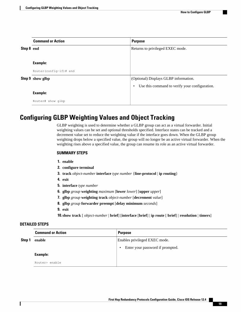
Configuring GLBP Weighting Values and Object TrackingGLBP weighting is used to determine whether a GLBP group can act as a virtual forwarder. Initialweighting values can be set and optional thresholds specified. Interface states can be tracked and adecrement value set to reduce the weighting value if the interface goes down. When the GLBP groupweighting drops below a specified value, the group will no longer be an active virtual forwarder. When theweighting rises above a specified value, the group can resume its role as an active virtual forwarder.
SUMMARY STEPS
1. enable
2. configure terminal
3. track object-number interface type number {line-protocol | ip routing}
4. exit
5. interface type number
6. glbp group weighting maximum [lower lower] [upper upper]
7. glbp group weighting track object-number [decrement value]
8. glbp group forwarder preempt [delay minimum seconds]
9. exit
10. show track [ object-number | brief] [interface [brief] | ip route [ brief] | resolution | timers]
DETAILED STEPS
Command or Action Purpose
Step 1 enable
Example:
Router> enable
Enables privileged EXEC mode.
• Enter your password if prompted.
Configuring GLBP Weighting Values and Object TrackingHow to Configure GLBP
First Hop Redundancy Protocols Configuration Guide, Cisco IOS Release 12.4 19
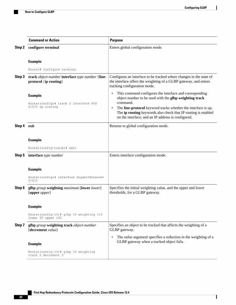
Command or Action Purpose
Step 2 configure terminal
Example:
Router# configure terminal
Enters global configuration mode.
Step 3 track object-number interface type number {line-protocol | ip routing}
Example:
Router(config)# track 2 interface POS 6/0/0 ip routing
Configures an interface to be tracked where changes in the state ofthe interface affect the weighting of a GLBP gateway, and enterstracking configuration mode.
• This command configures the interface and correspondingobject number to be used with the glbp weighting trackcommand.
• The line-protocol keyword tracks whether the interface is up.The ip routing keywords also check that IP routing is enabledon the interface, and an IP address is configured.
Step 4 exit
Example:
Router(config-track)# exit
Returns to global configuration mode.
Step 5 interface type number
Example:
Router(config)# interface GigabitEthernet 0/0/0
Enters interface configuration mode.
Step 6 glbp group weighting maximum [lower lower][upper upper]
Example:
Router(config-if)# glbp 10 weighting 110 lower 95 upper 105
Specifies the initial weighting value, and the upper and lowerthresholds, for a GLBP gateway.
Step 7 glbp group weighting track object-number[decrement value]
Example:
Router(config-if)# glbp 10 weighting track 2 decrement 5
Specifies an object to be tracked that affects the weighting of aGLBP gateway.
• The value argument specifies a reduction in the weighting of aGLBP gateway when a tracked object fails.
Configuring GLBP How to Configure GLBP
First Hop Redundancy Protocols Configuration Guide, Cisco IOS Release 12.420
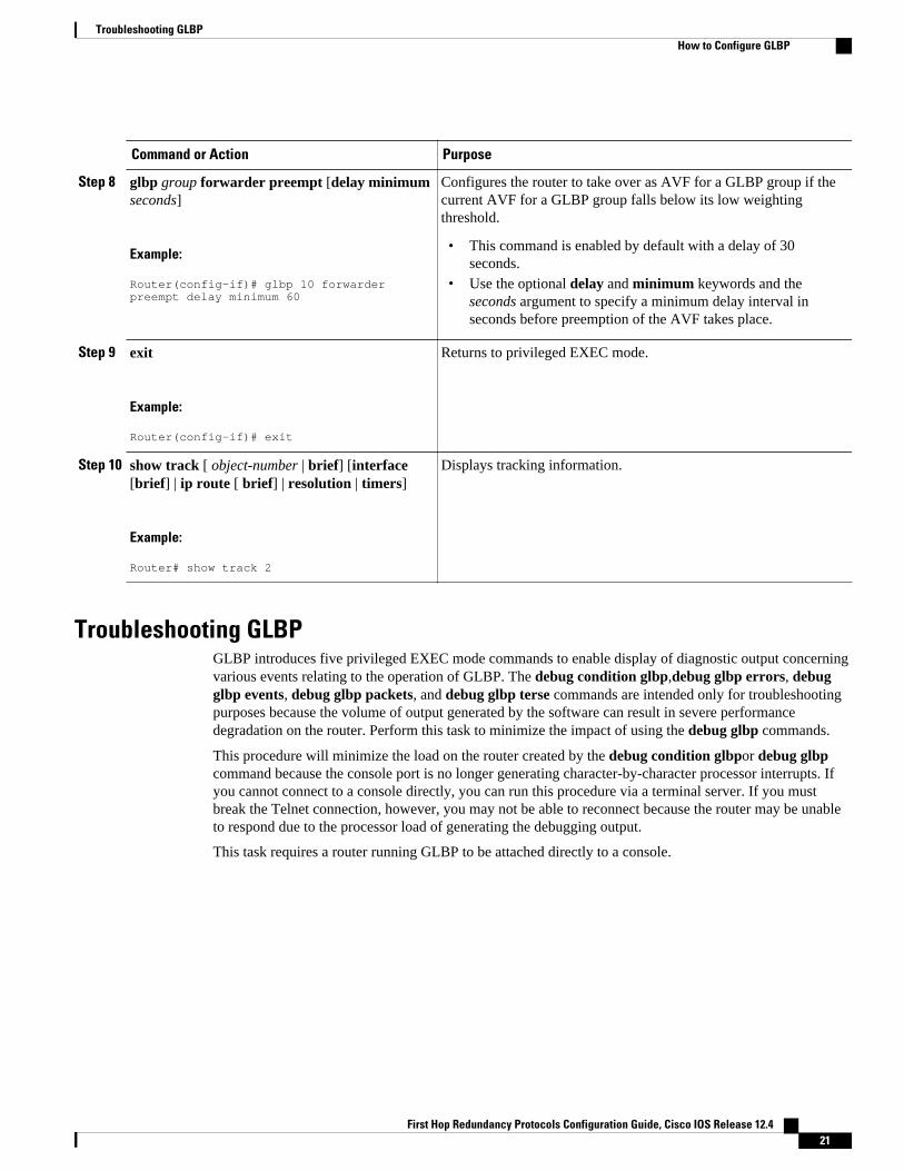
Command or Action Purpose
Step 8 glbp group forwarder preempt [delay minimumseconds]
Example:
Router(config-if)# glbp 10 forwarder preempt delay minimum 60
Configures the router to take over as AVF for a GLBP group if thecurrent AVF for a GLBP group falls below its low weightingthreshold.
• This command is enabled by default with a delay of 30seconds.
• Use the optional delay and minimum keywords and theseconds argument to specify a minimum delay interval inseconds before preemption of the AVF takes place.
Step 9 exit
Example:
Router(config-if)# exit
Returns to privileged EXEC mode.
Step 10 show track [ object-number | brief] [interface[brief] | ip route [ brief] | resolution | timers]
Example:
Router# show track 2
Displays tracking information.
Troubleshooting GLBPGLBP introduces five privileged EXEC mode commands to enable display of diagnostic output concerningvarious events relating to the operation of GLBP. The debug condition glbp,debug glbp errors, debugglbp events, debug glbp packets, and debug glbp terse commands are intended only for troubleshootingpurposes because the volume of output generated by the software can result in severe performancedegradation on the router. Perform this task to minimize the impact of using the debug glbp commands.
This procedure will minimize the load on the router created by the debug condition glbpor debug glbpcommand because the console port is no longer generating character-by-character processor interrupts. Ifyou cannot connect to a console directly, you can run this procedure via a terminal server. If you mustbreak the Telnet connection, however, you may not be able to reconnect because the router may be unableto respond due to the processor load of generating the debugging output.
This task requires a router running GLBP to be attached directly to a console.
Troubleshooting GLBPHow to Configure GLBP
First Hop Redundancy Protocols Configuration Guide, Cisco IOS Release 12.4 21
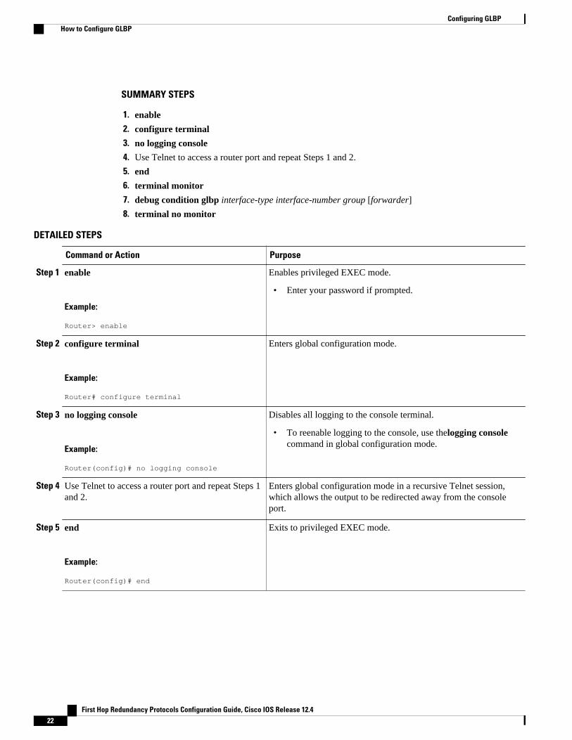
SUMMARY STEPS
1. enable
2. configure terminal
3. no logging console
4. Use Telnet to access a router port and repeat Steps 1 and 2.
5. end
6. terminal monitor
7. debug condition glbp interface-type interface-number group [forwarder]
8. terminal no monitor
DETAILED STEPS
Command or Action Purpose
Step 1 enable
Example:
Router> enable
Enables privileged EXEC mode.
• Enter your password if prompted.
Step 2 configure terminal
Example:
Router# configure terminal
Enters global configuration mode.
Step 3 no logging console
Example:
Router(config)# no logging console
Disables all logging to the console terminal.
• To reenable logging to the console, use thelogging consolecommand in global configuration mode.
Step 4 Use Telnet to access a router port and repeat Steps 1and 2.
Enters global configuration mode in a recursive Telnet session,which allows the output to be redirected away from the consoleport.
Step 5 end
Example:
Router(config)# end
Exits to privileged EXEC mode.
Configuring GLBP How to Configure GLBP
First Hop Redundancy Protocols Configuration Guide, Cisco IOS Release 12.422
Command or Action Purpose
Step 6 terminal monitor
Example:
Router# terminal monitor
Enables logging output on the virtual terminal.
Step 7 debug condition glbp interface-type interface-number group [forwarder]
Example:
Router# debug condition glbp GigabitEthernet0/0/0 1
Displays debugging messages about GLBP conditions.
• Try to enter only specific debug condition glbp or debugglbp commands to isolate the output to a certainsubcomponent and minimize the load on the processor. Useappropriate arguments and keywords to generate more detaileddebug information on specified subcomponents.
• Enter the specific no debug condition glbp or no debug glbpcommand when you are finished.
Step 8 terminal no monitor
Example:
Router# terminal no monitor
Disables logging on the virtual terminal.
Configuration Examples for GLBP• Example: Customizing GLBP Configuration, page 23• Example: Configuring GLBP MD5 Authentication Using Key Strings, page 23• Example: Configuring GLBP MD5 Authentication Using Key Chains, page 24• Example: Configuring GLBP Text Authentication, page 24• Example: Configuring GLBP Weighting, page 24• Example: Enabling GLBP Configuration, page 24
Example: Customizing GLBP ConfigurationRouter(config)# interface fastethernet 0/0Router(config-if)# ip address 10.21.8.32 255.255.255.0Router(config-if)# glbp 10 timers 5 18Router(config-if)# glbp 10 timers redirect 1800 28800Router(config-if)# glbp 10 load-balancing host-dependentRouter(config-if)# glbp 10 priority 254Router(config-if)# glbp 10 preempt delay minimum 60Router(config-if)# glbp 10 client-cache maximum 1200 timeout 245
Example: Configuring GLBP MD5 Authentication Using Key StringsThe following example shows how to configure GLBP MD5 authentication using a key string:
Router(config)# interface Ethernet 0/1
Example: Customizing GLBP ConfigurationConfiguration Examples for GLBP
First Hop Redundancy Protocols Configuration Guide, Cisco IOS Release 12.4 23

Router(config-if)# ip address 10.0.0.1 255.255.255.0Router(config-if)# glbp 2 authentication md5 key-string ThisStringIsTheSecretKeyRouter(config-if)# glbp 2 ip 10.0.0.10
Example: Configuring GLBP MD5 Authentication Using Key ChainsIn the following example, GLBP queries the key chain “AuthenticateGLBP” to obtain the current live keyand key ID for the specified key chain:
Router(config)# key chain AuthenticateGLBPRouter(config-keychain)# key 1Router(config-keychain-key)# key-string ThisIsASecretKeyRouter(config-keychain-key)# exitRouter(config-keychain)# exitRouter(config)# interface Ethernet 0/1Router(config-if)# ip address 10.0.0.1 255.255.255.0Router(config-if)# glbp 2 authentication md5 key-chain AuthenticateGLBPRouter(config-if)# glbp 2 ip 10.0.0.10
Example: Configuring GLBP Text AuthenticationRouter(config)# interface GigabitEthernet 0/0/0Router(config-if)# ip address 10.21.8.32 255.255.255.0Router(config-if)# glbp 10 authentication text stringxyzRouter(config-if)# glbp 10 ip 10.21.8.10
Example: Configuring GLBP WeightingIn the following example, Router A is configured to track the IP routing state of the POS interface 5/0/0and 6/0/0, an initial GLBP weighting with upper and lower thresholds is set, and a weighting decrementvalue of 10 is set. If POS interface 5/0/0 and 6/0/0 goes down, the weighting value of the router is reduced.
Router(config)# track 1 interface POS 5/0/0 ip routingRouter(config)# track 2 interface POS 6/0/0 ip routingRouter(config)# interface fastethernet 0/0/0Router(config-if)# glbp 10 weighting 110 lower 95 upper 105Router(config-if)# glbp 10 weighting track 1 decrement 10Router(config-if)# glbp 10 weighting track 2 decrement 10Router(config-if)# glbp 10 forwarder preempt delay minimum 60
Example: Enabling GLBP ConfigurationIn the following example, Router A is configured to enable GLBP, and the virtual IP address of 10.21.8.10is specified for GLBP group 10:
Router(config)# interface GigabitEthernet 0/0/0Router(config-if)# ip address 10.21.8.32 255.255.255.0Router(config-if)# glbp 10 ip 10.21.8.10
Additional References
Example: Configuring GLBP MD5 Authentication Using Key Chains Additional References
First Hop Redundancy Protocols Configuration Guide, Cisco IOS Release 12.424
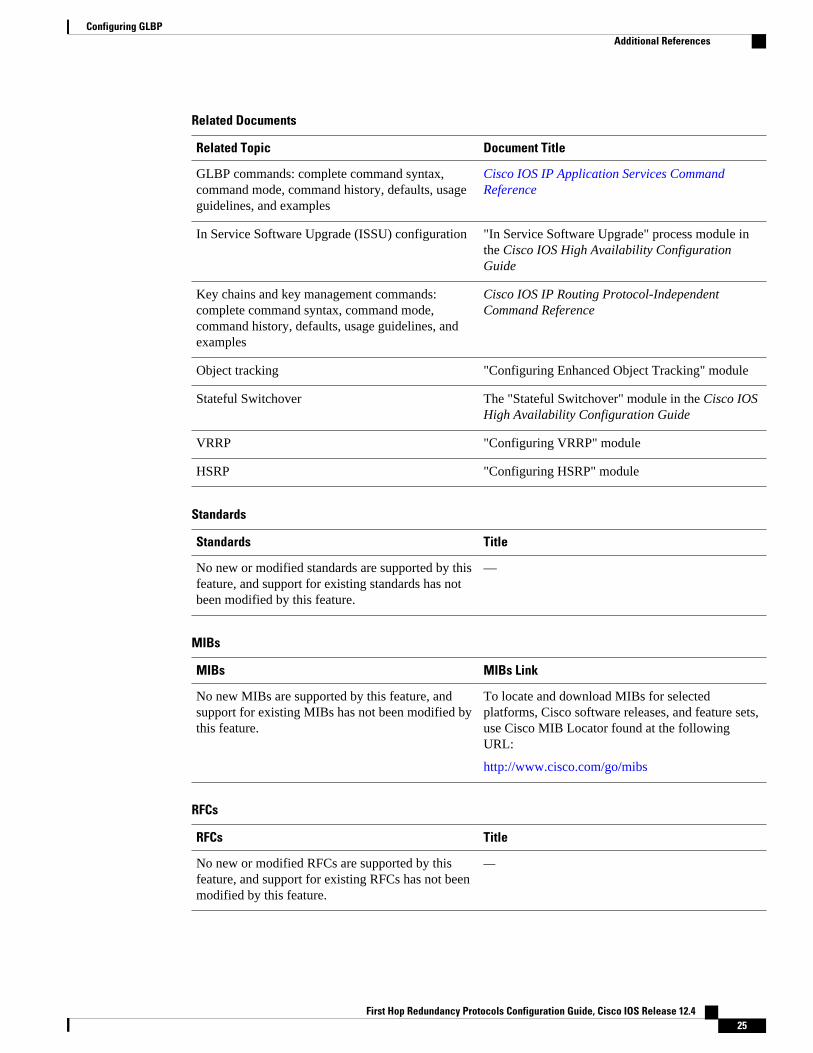
Related Documents
Related Topic Document Title
GLBP commands: complete command syntax,command mode, command history, defaults, usageguidelines, and examples
Cisco IOS IP Application Services CommandReference
In Service Software Upgrade (ISSU) configuration "In Service Software Upgrade" process module inthe Cisco IOS High Availability ConfigurationGuide
Key chains and key management commands:complete command syntax, command mode,command history, defaults, usage guidelines, andexamples
Cisco IOS IP Routing Protocol-IndependentCommand Reference
Object tracking "Configuring Enhanced Object Tracking" module
Stateful Switchover The "Stateful Switchover" module in the Cisco IOSHigh Availability Configuration Guide
VRRP "Configuring VRRP" module
HSRP "Configuring HSRP" module
Standards
Standards Title
No new or modified standards are supported by thisfeature, and support for existing standards has notbeen modified by this feature.
—
MIBs
MIBs MIBs Link
No new MIBs are supported by this feature, andsupport for existing MIBs has not been modified bythis feature.
To locate and download MIBs for selectedplatforms, Cisco software releases, and feature sets,use Cisco MIB Locator found at the followingURL:
http://www.cisco.com/go/mibs
RFCs
RFCs Title
No new or modified RFCs are supported by thisfeature, and support for existing RFCs has not beenmodified by this feature.
—
Configuring GLBPAdditional References
First Hop Redundancy Protocols Configuration Guide, Cisco IOS Release 12.4 25
Technical Assistance
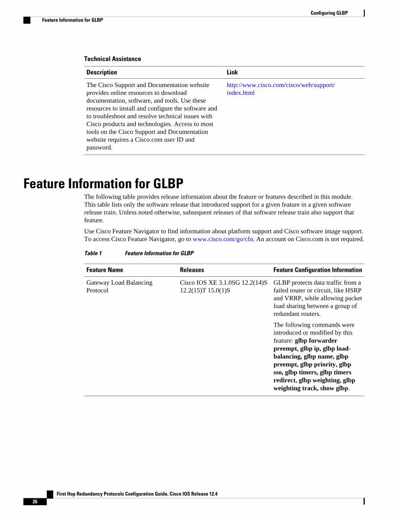
Description Link
The Cisco Support and Documentation websiteprovides online resources to downloaddocumentation, software, and tools. Use theseresources to install and configure the software andto troubleshoot and resolve technical issues withCisco products and technologies. Access to mosttools on the Cisco Support and Documentationwebsite requires a Cisco.com user ID andpassword.
http://www.cisco.com/cisco/web/support/index.html
Feature Information for GLBPThe following table provides release information about the feature or features described in this module.This table lists only the software release that introduced support for a given feature in a given softwarerelease train. Unless noted otherwise, subsequent releases of that software release train also support thatfeature.
Use Cisco Feature Navigator to find information about platform support and Cisco software image support.To access Cisco Feature Navigator, go to www.cisco.com/go/cfn. An account on Cisco.com is not required.
Table 1 Feature Information for GLBP
Feature Name Releases Feature Configuration Information
Gateway Load BalancingProtocol
Cisco IOS XE 3.1.0SG 12.2(14)S12.2(15)T 15.0(1)S
GLBP protects data traffic from afailed router or circuit, like HSRPand VRRP, while allowing packetload sharing between a group ofredundant routers.
The following commands wereintroduced or modified by thisfeature: glbp forwarderpreempt, glbp ip, glbp load-balancing, glbp name, glbppreempt, glbp priority, glbpsso, glbp timers, glbp timersredirect, glbp weighting, glbpweighting track, show glbp.
Configuring GLBP Feature Information for GLBP
First Hop Redundancy Protocols Configuration Guide, Cisco IOS Release 12.426
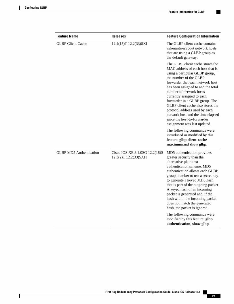
Feature Name Releases Feature Configuration Information
GLBP Client Cache 12.4(15)T 12.2(33)SXI The GLBP client cache containsinformation about network hoststhat are using a GLBP group asthe default gateway.
The GLBP client cache stores theMAC address of each host that isusing a particular GLBP group,the number of the GLBPforwarder that each network hosthas been assigned to and the totalnumber of network hostscurrently assigned to eachforwarder in a GLBP group. TheGLBP client cache also stores theprotocol address used by eachnetwork host and the time elapsedsince the host-to-forwarderassignment was last updated.
The following commands wereintroduced or modified by thisfeature: glbp client-cachemaximumand show glbp.
GLBP MD5 Authentication Cisco IOS XE 3.1.0SG 12.2(18)S12.3(2)T 12.2(33)SXH
MD5 authentication providesgreater security than thealternative plain textauthentication scheme. MD5authentication allows each GLBPgroup member to use a secret keyto generate a keyed MD5 hashthat is part of the outgoing packet.A keyed hash of an incomingpacket is generated and, if thehash within the incoming packetdoes not match the generatedhash, the packet is ignored.
The following commands weremodified by this feature: glbpauthentication, show glbp.
Configuring GLBPFeature Information for GLBP
First Hop Redundancy Protocols Configuration Guide, Cisco IOS Release 12.4 27
Feature Name Releases Feature Configuration Information
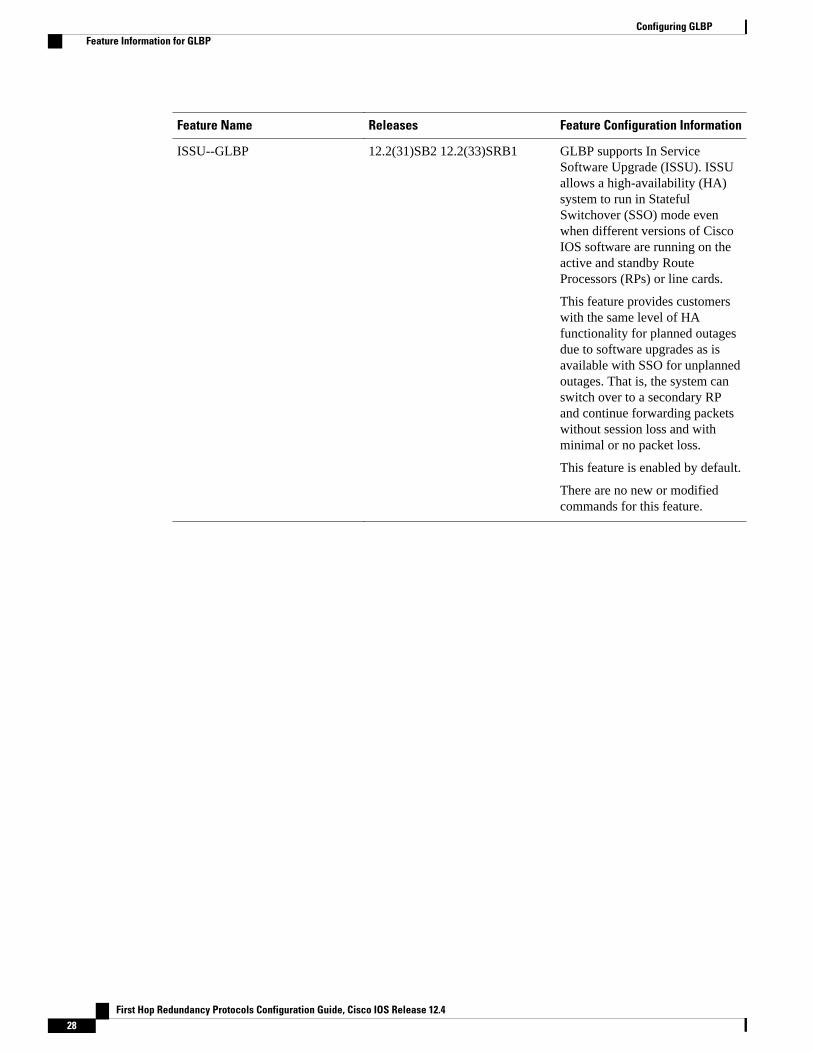
ISSU--GLBP 12.2(31)SB2 12.2(33)SRB1 GLBP supports In ServiceSoftware Upgrade (ISSU). ISSUallows a high-availability (HA)system to run in StatefulSwitchover (SSO) mode evenwhen different versions of CiscoIOS software are running on theactive and standby RouteProcessors (RPs) or line cards.
This feature provides customerswith the same level of HAfunctionality for planned outagesdue to software upgrades as isavailable with SSO for unplannedoutages. That is, the system canswitch over to a secondary RPand continue forwarding packetswithout session loss and withminimal or no packet loss.
This feature is enabled by default.
There are no new or modifiedcommands for this feature.
Configuring GLBP Feature Information for GLBP
First Hop Redundancy Protocols Configuration Guide, Cisco IOS Release 12.428
Feature Name Releases Feature Configuration Information
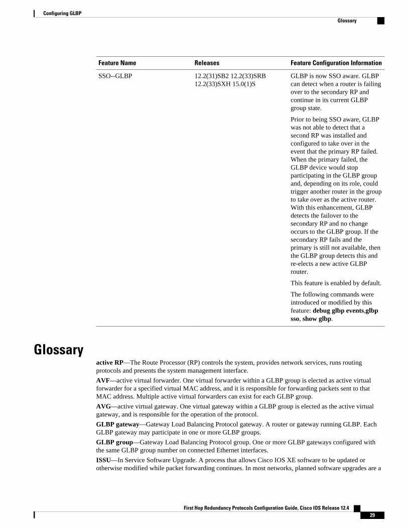
SSO--GLBP 12.2(31)SB2 12.2(33)SRB12.2(33)SXH 15.0(1)S
GLBP is now SSO aware. GLBPcan detect when a router is failingover to the secondary RP andcontinue in its current GLBPgroup state.
Prior to being SSO aware, GLBPwas not able to detect that asecond RP was installed andconfigured to take over in theevent that the primary RP failed.When the primary failed, theGLBP device would stopparticipating in the GLBP groupand, depending on its role, couldtrigger another router in the groupto take over as the active router.With this enhancement, GLBPdetects the failover to thesecondary RP and no changeoccurs to the GLBP group. If thesecondary RP fails and theprimary is still not available, thenthe GLBP group detects this andre-elects a new active GLBProuter.
This feature is enabled by default.
The following commands wereintroduced or modified by thisfeature: debug glbp events,glbpsso, show glbp.
Glossaryactive RP—The Route Processor (RP) controls the system, provides network services, runs routingprotocols and presents the system management interface.
AVF—active virtual forwarder. One virtual forwarder within a GLBP group is elected as active virtualforwarder for a specified virtual MAC address, and it is responsible for forwarding packets sent to thatMAC address. Multiple active virtual forwarders can exist for each GLBP group.
AVG—active virtual gateway. One virtual gateway within a GLBP group is elected as the active virtualgateway, and is responsible for the operation of the protocol.
GLBP gateway—Gateway Load Balancing Protocol gateway. A router or gateway running GLBP. EachGLBP gateway may participate in one or more GLBP groups.
GLBP group—Gateway Load Balancing Protocol group. One or more GLBP gateways configured withthe same GLBP group number on connected Ethernet interfaces.
ISSU—In Service Software Upgrade. A process that allows Cisco IOS XE software to be updated orotherwise modified while packet forwarding continues. In most networks, planned software upgrades are a
Configuring GLBPGlossary
First Hop Redundancy Protocols Configuration Guide, Cisco IOS Release 12.4 29
significant cause of downtime. ISSU allows Cisco IOS software to be modified while packet forwardingcontinues, which increases network availability and reduces downtime caused by planned softwareupgrades.
NSF—nonstop forwarding. The ability of a router to continue to forward traffic to a router that may berecovering from a failure. Also, the ability of a router recovering from a failure to continue to correctlyforward traffic sent to it by a peer.
RP—Route Processor. A generic term for the centralized control unit in a chassis. Platforms usually use aplatform-specific term, such as RSP on the Cisco 7500, the PRE on the Cisco 10000, or the SUP+MSFC onthe Cisco 7600.
RPR—Route Processor Redundancy. RPR provides an alternative to the High System Availability (HSA)feature. HSA enables a system to reset and use a standby Route Processor (RP) if the active RP fails. UsingRPR, you can reduce unplanned downtime because RPR enables a quicker switchover between an activeand standby RP if the active RP experiences a fatal error.
RPR+—An enhancement to RPR in which the standby RP is fully initialized.
SSO—Stateful Switchover. Enables applications and features to maintain state information between anactive and standby unit.
standby RP—An RP that has been fully initialized and is ready to assume control from the active RPshould a manual or fault-induced switchover occur.
switchover—An event in which system control and routing protocol execution are transferred from theactive RP to the standby RP. Switchover may be a manual operation or may be induced by a hardware orsoftware fault. Switchover may include transfer of the packet forwarding function in systems that combinesystem control and packet forwarding in an indivisible unit.
vIP—virtual IP address. An IPv4 address. There must be only one virtual IP address for each configuredGLBP group. The virtual IP address must be configured on at least one GLBP group member. Other GLBPgroup members can learn the virtual IP address from hello messages.
Cisco and the Cisco logo are trademarks or registered trademarks of Cisco and/or its affiliates in the U.S.and other countries. To view a list of Cisco trademarks, go to this URL: www.cisco.com/go/trademarks.Third-party trademarks mentioned are the property of their respective owners. The use of the word partnerdoes not imply a partnership relationship between Cisco and any other company. (1110R)
Any Internet Protocol (IP) addresses and phone numbers used in this document are not intended to beactual addresses and phone numbers. Any examples, command display output, network topology diagrams,and other figures included in the document are shown for illustrative purposes only. Any use of actual IPaddresses or phone numbers in illustrative content is unintentional and coincidental.
Configuring GLBP
First Hop Redundancy Protocols Configuration Guide, Cisco IOS Release 12.430
Configuring HSRP
The Hot Standby Router Protocol (HSRP) is a First Hop Redundancy Protocol (FHRP) designed to allowfor transparent failover of the first-hop IP router. HSRP provides high network availability by providingfirst-hop routing redundancy for IP hosts on networks configured with a default gateway IP address.HSRP is used in a group of routers for selecting an active router and a standby router. In a group of routerinterfaces, the active router is the router of choice for routing packets; the standby router is the router thattakes over when the active router fails or when preset conditions are met.
• Finding Feature Information, page 31• Restrictions for HSRP, page 31• Information About HSRP, page 32• How to Configure HSRP, page 48• Configuration Examples for HSRP, page 88• Additional References, page 97• Feature Information for HSRP, page 99• Glossary, page 103
Finding Feature InformationYour software release may not support all the features documented in this module. For the latest featureinformation and caveats, see the release notes for your platform and software release. To find informationabout the features documented in this module, and to see a list of the releases in which each feature issupported, see the Feature Information Table at the end of this document.
Use Cisco Feature Navigator to find information about platform support and Cisco software image support.To access Cisco Feature Navigator, go to www.cisco.com/go/cfn. An account on Cisco.com is not required.
Restrictions for HSRP• HSRP is designed for use over multiaccess, multicast, or broadcast capable Ethernet LANs. HSRP is
not intended as a replacement for existing dynamic protocols.• HSRP is configurable on Ethernet, FDDI, BVI, LANE, or Token Ring interfaces. Token Ring
interfaces allow up to three Hot Standby groups each, the group numbers being 0, 1, and 2.• The Cisco 2500 series, Cisco 3000 series, Cisco 4000 series, and Cisco 4500 routers that use Lance
Ethernet hardware do not support multiple Hot Standby groups on a single Ethernet interface. TheCisco 800 series and Cisco 1600 series that use PQUICC Ethernet hardware do not support multipleHot Standby groups on a single Ethernet interface. You can configure a workaround solution by using
First Hop Redundancy Protocols Configuration Guide, Cisco IOS Release 12.4 31
the standby use-bia interface configuration command, which uses the burned-in address of theinterface as its virtual MAC address, instead of the preassigned MAC address.
• HSRP support for Bidirectional Forwarding Detection (BFD) is not available for all platforms andinterfaces.
• The same HSRP group number or HSRP MAC address cannot be configured on different subinterfacesof the same major interface.
Note This restriction was removed in Cisco IOS Release 12.4(14), 12.4(15)T, 12.2(33)SRB,12.2(33)SXH, and later releases.
• Enhanced Object Tracking (EOT) is not stateful switchover (SSO)-aware and cannot be used withHSRP in SSO mode.
Information About HSRP• HSRP Operation, page 33
• HSRP Version 2 Design, page 34
• HSRP Configuration Changes, page 35
• HSRP Benefits, page 35
• HSRP Groups and Group Attributes, page 36
• HSRP Preemption, page 36
• HSRP Priority and Preemption, page 36
• How Object Tracking Affects the Priority of an HSRP Router, page 36
• HSRP Addressing, page 37
• HSRP Virtual MAC Addresses and BIA MAC Addresses, page 37
• HSRP Timers, page 38
• HSRP MAC Refresh Interval, page 38
• HSRP Text Authentication, page 38
• HSRP MD5 Authentication, page 38
• HSRP Support for IPv6, page 39
• HSRP Messages and States, page 39
• HSRP Group Linking to IP Redundancy Clients, page 40
• HSRP and ARP, page 40
• HSRP Gratuitous ARP, page 40
• HSRP Object Tracking, page 41
• HSRP Group Shutdown, page 41
• HSRP Support for ICMP Redirect Messages, page 41
• ICMP Redirects to Active HSRP Routers, page 42
• ICMP Redirects to Passive HSRP Routers, page 43
• ICMP Redirects to Non-HSRP Routers, page 43
• Passive HSRP Router Advertisements, page 43
• ICMP Redirects Not Sent, page 44
• HSRP Support for MPLS VPNs, page 44
• HSRP Multiple Group Optimization, page 45
Configuring HSRP Information About HSRP
First Hop Redundancy Protocols Configuration Guide, Cisco IOS Release 12.432
• HSRP--ISSU, page 45
• SSO HSRP, page 45
• HSRP BFD Peering, page 46
• HSRP MIB Traps, page 47
HSRP OperationMost IP hosts have an IP address of a single router configured as the default gateway. When HSRP is used,the HSRP virtual IP address is configured as the host’s default gateway instead of the IP address of therouter.
HSRP is useful for hosts that do not support a router discovery protocol (such as ICMP Router DiscoveryProtocol [IRDP]) and cannot switch to a new router when their selected router reloads or loses power.Because existing TCP sessions can survive the failover, this protocol also provides a more transparentrecovery for hosts that dynamically choose a next hop for routing IP traffic.
When HSRP is configured on a network segment, it provides a virtual MAC address and an IP address thatis shared among a group of routers running HSRP. The address of this HSRP group is referred to as thevirtual IP address. One of these devices is selected by the protocol to be the active router. The active routerreceives and routes packets destined for the MAC address of the group. For n routers running HSRP, n+ 1IP and MAC addresses are assigned.
HSRP detects when the designated active router fails, at which point a selected standby router assumescontrol of the MAC and IP addresses of the Hot Standby group. A new standby router is also selected atthat time.
HSRP uses a priority mechanism to determine which HSRP configured router is to be the default activerouter. To configure a router as the active router, you assign it a priority that is higher than the priority ofall the other HSRP-configured routers. The default priority is 100, so if you configure just one router tohave a higher priority, that router will be the default active router.
Devices that are running HSRP send and receive multicast UDP-based hello messages to detect routerfailure and to designate active and standby routers. When the active router fails to send a hello messagewithin a configurable period of time, the standby router with the highest priority becomes the active router.The transition of packet forwarding functions between routers is completely transparent to all hosts on thenetwork.
You can configure multiple Hot Standby groups on an interface, thereby making fuller use of redundantrouters and load sharing.
The figure below shows a network configured for HSRP. By sharing a virtual MAC address and IP address,two or more routers can act as a single virtual router. The virtual router does not physically exist butrepresents the common default gateway for routers that are configured to provide backup to each other.You do not need to configure the hosts on the LAN with the IP address of the active router. Instead, youconfigure them with the IP address (virtual IP address) of the virtual router as their default gateway. If the
HSRP OperationInformation About HSRP
First Hop Redundancy Protocols Configuration Guide, Cisco IOS Release 12.4 33
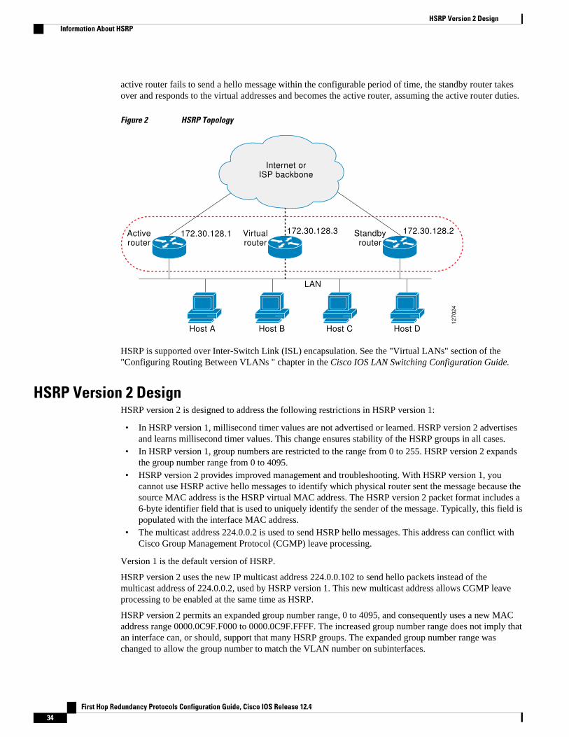
active router fails to send a hello message within the configurable period of time, the standby router takesover and responds to the virtual addresses and becomes the active router, assuming the active router duties.
Figure 2 HSRP Topology
172.30.128.1 172.30.128.3 172.30.128.2Active router
Virtual router
Standby router
127
02
4
Internet or ISP backbone
Host A Host B
LAN
Host C Host D
HSRP is supported over Inter-Switch Link (ISL) encapsulation. See the "Virtual LANs" section of the"Configuring Routing Between VLANs " chapter in the Cisco IOS LAN Switching Configuration Guide.
HSRP Version 2 DesignHSRP version 2 is designed to address the following restrictions in HSRP version 1:
• In HSRP version 1, millisecond timer values are not advertised or learned. HSRP version 2 advertisesand learns millisecond timer values. This change ensures stability of the HSRP groups in all cases.
• In HSRP version 1, group numbers are restricted to the range from 0 to 255. HSRP version 2 expandsthe group number range from 0 to 4095.
• HSRP version 2 provides improved management and troubleshooting. With HSRP version 1, youcannot use HSRP active hello messages to identify which physical router sent the message because thesource MAC address is the HSRP virtual MAC address. The HSRP version 2 packet format includes a6-byte identifier field that is used to uniquely identify the sender of the message. Typically, this field ispopulated with the interface MAC address.
• The multicast address 224.0.0.2 is used to send HSRP hello messages. This address can conflict withCisco Group Management Protocol (CGMP) leave processing.
Version 1 is the default version of HSRP.
HSRP version 2 uses the new IP multicast address 224.0.0.102 to send hello packets instead of themulticast address of 224.0.0.2, used by HSRP version 1. This new multicast address allows CGMP leaveprocessing to be enabled at the same time as HSRP.
HSRP version 2 permits an expanded group number range, 0 to 4095, and consequently uses a new MACaddress range 0000.0C9F.F000 to 0000.0C9F.FFFF. The increased group number range does not imply thatan interface can, or should, support that many HSRP groups. The expanded group number range waschanged to allow the group number to match the VLAN number on subinterfaces.
HSRP Version 2 Design Information About HSRP
First Hop Redundancy Protocols Configuration Guide, Cisco IOS Release 12.434
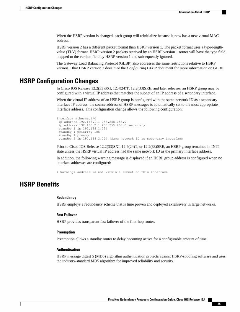
When the HSRP version is changed, each group will reinitialize because it now has a new virtual MACaddress.
HSRP version 2 has a different packet format than HSRP version 1. The packet format uses a type-length-value (TLV) format. HSRP version 2 packets received by an HSRP version 1 router will have the type fieldmapped to the version field by HSRP version 1 and subsequently ignored.
The Gateway Load Balancing Protocol (GLBP) also addresses the same restrictions relative to HSRPversion 1 that HSRP version 2 does. See the Configuring GLBP document for more information on GLBP.
HSRP Configuration ChangesIn Cisco IOS Release 12.2(33)SXI, 12.4(24)T, 12.2(33)SRE, and later releases, an HSRP group may beconfigured with a virtual IP address that matches the subnet of an IP address of a secondary interface.
When the virtual IP address of an HSRP group is configured with the same network ID as a secondaryinterface IP address, the source address of HSRP messages is automatically set to the most appropriateinterface address. This configuration change allows the following configuration:
interface Ethernet1/0 ip address 192.168.1.1 255.255.255.0 ip address 192.168.2.1 255.255.255.0 secondary standby 1 ip 192.168.1.254 standby 1 priority 105 standby 1 preempt standby 2 ip 192.168.2.254 !Same network ID as secondary interface
Prior to Cisco IOS Release 12.2(33)SXI, 12.4(24)T, or 12.2(33)SRE, an HSRP group remained in INITstate unless the HSRP virtual IP address had the same network ID as the primary interface address.
In addition, the following warning message is displayed if an HSRP group address is configured when nointerface addresses are configured:
% Warning: address is not within a subnet on this interface
HSRP Benefits
Redundancy
HSRP employs a redundancy scheme that is time proven and deployed extensively in large networks.
Fast Failover
HSRP provides transparent fast failover of the first-hop router.
Preemption
Preemption allows a standby router to delay becoming active for a configurable amount of time.
Authentication
HSRP message digest 5 (MD5) algorithm authentication protects against HSRP-spoofing software and usesthe industry-standard MD5 algorithm for improved reliability and security.
HSRP Configuration ChangesInformation About HSRP
First Hop Redundancy Protocols Configuration Guide, Cisco IOS Release 12.4 35
HSRP Groups and Group AttributesYou can use the CLI to apply group attributes to:
• A single HSRP group—performed in interface configuration mode and applies to a group.• All groups on the interface—performed in interface configuration mode and applies to all groups on
the interface.• All groups on all interfaces—performed in global configuration mode and applies to all groups on all
interfaces.
HSRP PreemptionWhen a newly reloaded router becomes HSRP active, and there is already an HSRP active router on thenetwork, HSRP preemption may appear to not function. HSRP preemption may appear not functioncorrectly because the new HSRP active router did not receive any hello packets from the current HSRPactive router, and the preemption configuration never factored into the new router's decision making.
HSRP may appear to not function on some larger hardware platforms where there can be a delay in aninterface receiving packets.
In general, we recommend that all HSRP routers have the following configuration:
standby delay minimum 30 reload 60
The standby delay minimum reload interface configuration command delays HSRP groups frominitializing for the specified time after the interface comes up.
This is a different command than the standby preempt delay interface configuration command, whichenables HSRP preemption delay.
HSRP Priority and PreemptionPreemption enables the HSRP router with the highest priority to immediately become the active router.Priority is determined first by the configured priority value, and then by the IP address. In case of ties, theprimary IP addresses are compared, and the higher IP address has priority. In each case, a higher value is ofgreater priority. If you do not use the standby preempt interface configuration command in theconfiguration for a router, that router will not become the active router, even if its priority is higher than allother routers.
A standby router with equal priority but a higher IP address will not preempt the active router.
When a router first comes up, it does not have a complete routing table. You can set a preemption delaythat allows preemption to be delayed for a configurable time period. This delay period allows the router topopulate its routing table before becoming the active router.
If preemption is not enabled, then a router may appear to preempt the active router if it does not receive anyHello messages from the active router.
How Object Tracking Affects the Priority of an HSRP RouterThe priority of a device can change dynamically if it has been configured for object tracking and the objectthat is being tracked goes down. The tracking process periodically polls the tracked objects and notes anychange of value. The changes in the tracked object are communicated to HSRP, either immediately or aftera specified delay. The object values are reported as either up or down. Examples of objects that can betracked are the line protocol state of an interface or the reachability of an IP route. If the specified object
HSRP Groups and Group Attributes Information About HSRP
First Hop Redundancy Protocols Configuration Guide, Cisco IOS Release 12.436
goes down, the HSRP priority is reduced. The HSRP router with the higher priority can become the activerouter if it has the standby preempt command configured.
HSRP AddressingHSRP routers communicate between each other by exchanging HSRP hello packets. These packets are sentto the destination IP multicast address 224.0.0.2 (reserved multicast address used to communicate to allrouters) on UDP port 1985. The active router sources hello packets from its configured IP address and theHSRP virtual MAC address while the standby router sources hellos from its configured IP address and theinterface MAC address, which may or may not be the burned-in MAC address.
Because hosts are configured with their default gateway as the HSRP virtual IP address, hosts mustcommunicate with the MAC address associated with the HSRP virtual IP address. This MAC address willbe a virtual MAC address in the format of 0000.0C07.ACxy, where xy is the HSRP group number inhexadecimal based on the respective interface. For example, HSRP group one will use the HSRP virtualMAC address of 0000.0C07.AC01. Hosts on the adjoining LAN segment use the normal AddressResolution Protocol (ARP) process to resolve the associated MAC addresses.
Token Ring interfaces use functional addresses for the HSRP MAC address. Functional addresses are theonly general multicast mechanism available. A limited number of Token Ring functional addresses areavailable, and many of them are reserved for other functions. The following are the only three addressesavailable for use with HSRP:
• c000.0001.0000 (group 0)• c000.0002.0000 (group 1)• c000.0004.0000 (group 2)
Thus, only three HSRP groups may be configured on Token Ring interfaces unless the standby use-biainterface configuration command is configured.
HSRP version 2 uses the new IP multicast address 224.0.0.102 to send hello packets instead of themulticast address of 224.0.0.2, which is used by version 1. This new multicast address allows Cisco GroupManagement Protocol (CGMP) leave processing to be enabled at the same time as HSRP.
HSRP version 2 permits an expanded group number range, 0 to 4095, and consequently uses a new MACaddress range 0000.0C9F.F000 to 0000.0C9F.FFFF.
HSRP Virtual MAC Addresses and BIA MAC AddressesA router automatically generates a virtual MAC address for each HSRP router. However, some networkimplementations, such as Advanced Peer-to-Peer Networking (APPN), use the MAC address to identify thefirst hop for routing purposes. In this case, specify the virtual MAC address by using the standby mac-address command in the group; the virtual IP address is unimportant for these protocols.
The standby use-bia command was implemented to overcome the limitations of using a functional addressfor the HSRP MAC address on Token Ring interfaces. This command allows HSRP groups to use theburned-in MAC address of an interface instead of the HSRP virtual MAC address. When HSRP runs on amultiple-ring, source-routed bridging environment and the HSRP routers reside on different rings,configuring the standby use-bia command can prevent confusion about the routing information field(RFI).
The standby use-bia command is used for an interface and the standby mac-address command is used foran HSRP group.
HSRP AddressingInformation About HSRP
First Hop Redundancy Protocols Configuration Guide, Cisco IOS Release 12.4 37
HSRP TimersEach HSRP router maintains three timers that are used for timing hello messages: an active timer, a standbytimer, and a hello timer. When a timer expires, the router changes to a new HSRP state. Routers or accessservers for which timer values are not configured can learn timer values from the active or standby router.The timers configured on the active router always override any other timer settings. All routers in a HotStandby group should use the same timer values.
For HSRP version 1, nonactive routers learn timer values from the active router, unless millisecond timervalues are being used. If millisecond timer values are being used, all routers must be configured with themillisecond timer values. This rule applies if either the hello time or the hold time is specified inmilliseconds. This configuration is necessary because the HSRP hello packets advertise the timer values inseconds. HSRP version 2 does not have this limitation; it advertises the timer values in milliseconds.
HSRP MAC Refresh IntervalWhen HSRP runs over FDDI, you can change the interval at which a packet is sent to refresh the MACcache on learning bridges and switches. HSRP hello packets on FDDI interfaces use the burned-in address(BIA) instead of the MAC virtual address. Refresh packets keep the MAC cache on switches and learningbridges current. Refresh packets are also used for HSRP groups configured as multigroup slaves becausethese do not send regular Hello messages.
You can change the refresh interval on FDDI rings to a longer or shorter interval, thereby using bandwidthmore efficiently. You can prevent the sending of any MAC refresh packets if you do not need them (if youhave FDDI but do not have a learning bridge or switch).
HSRP Text AuthenticationHSRP ignores unauthenticated HSRP protocol messages. The default authentication type is textauthentication.
HSRP authentication protects against false HSRP hello packets causing a denial-of-service attack. Forexample, Router A has a priority of 120 and is the active router. If a host sends spoof HSRP hello packetswith a priority of 130, then Router A stops being the active router. If Router A has authenticationconfigured such that the spoof HSRP hello packets are ignored, Router A will remain the active router.
HSRP packets will be rejected in any of the following cases:
• The authentication schemes differ on the router and in the incoming packets.• Text authentication strings differ on the router and in the incoming packet.
HSRP MD5 AuthenticationBefore the introduction of HSRP MD5 authentication, HSRP authenticated protocol packets with a simpleplain text string. HSRP MD5 authentication is an enhancement to generate an MD5 digest for the HSRPportion of the multicast HSRP protocol packet. This functionality provides added security and protectsagainst the threat from HSRP-spoofing software.
MD5 authentication provides greater security than the alternative plain text authentication scheme. MD5authentication allows each HSRP group member to use a secret key to generate a keyed MD5 hash that ispart of the outgoing packet. A keyed hash of an incoming packet is generated and if the hash within theincoming packet does not match the generated hash, the packet is ignored.
HSRP Timers Information About HSRP
First Hop Redundancy Protocols Configuration Guide, Cisco IOS Release 12.438
The key for the MD5 hash can be either given directly in the configuration using a key string or suppliedindirectly through a key chain.
HSRP has two authentication schemes:
• Plain text authentication• MD5 authentication
HSRP authentication protects against false HSRP hello packets causing a denial-of-service attack. Forexample, Router A has a priority of 120 and is the active router. If a host sends spoof HSRP hello packetswith a priority of 130, then Router A stops being the active router. If Router A has authenticationconfigured such that the spoof HSRP hello packets are ignored, Router A will remain the active router.
HSRP packets will be rejected in any of the following cases:
• The authentication schemes differ on the router and in the incoming packets.• MD5 digests differ on the router and in the incoming packet.• Text authentication strings differ on the router and in the incoming packet.
HSRP Support for IPv6Most IPv4 hosts have a single router’s IP address configured as the default gateway. When HSRP is used,then the HSRP virtual IP address is configured as the host’s default gateway instead of the router’s IPaddress. Simple load sharing may be achieved by using two HSRP groups and configuring half the hostswith one virtual IP address and half the hosts with the other virtual IP address.
In contrast, IPv6 hosts learn of available IPv6 routers through IPv6 neighbor discovery RouterAdvertisement (RA) messages. These are multicast periodically, or may be solicited by hosts. HSRP isdesigned to provide only a virtual first hop for IPv6 hosts.
An HSRP IPv6 group has a virtual MAC address that is derived from the HSRP group number, and avirtual IPv6 link-local address that is, by default, derived from the HSRP virtual MAC address. HSRP IPv6uses the MAC address range 0005.73A0.0000 to 0005.73A0.0FFF. Periodic RAs are sent for the HSRPvirtual IPv6 link-local address when the HSRP group is active. These RAs stop after a final RA is sentwhen the group leaves the active state.
Periodic RAs for the interface link-local address stop after a final RA is sent while at least one virtual IPv6link-local address is configured on the interface. No restrictions occur for the interface IPv6 link-localaddress other than that mentioned for the RAs. Other protocols continue to receive and send packets to thisaddress.
HSRP uses a priority mechanism to determine which HSRP configured router is to be the default activerouter. To configure a router as the active router, you assign it a priority that is higher than the priority ofall the other HSRP-configured routers. The default priority is 100, so if you configure just one router tohave a higher priority, that router will be the default active router.
For more information see the "Configuring First Hop Redundancy Protocols in IPv6" chapter of the CiscoIOS IPv6 Configuration Guide.
HSRP Messages and StatesRouters configured with HSRP exchange three types of multicast messages:
• Coup—When a standby router wants to assume the function of the active router, it sends a coupmessage.
• Hello—The hello message conveys to other HSRP routers the HSRP priority and state information ofthe router.
HSRP Support for IPv6Information About HSRP
First Hop Redundancy Protocols Configuration Guide, Cisco IOS Release 12.4 39
• Resign—A router that is the active router sends this message when it is about to shut down or when arouter that has a higher priority sends a hello or coup message.
At any time, a router configured with HSRP is in one of the following states:
• Active—The router is performing packet-transfer functions.• Init or Disabled—The router is not yet ready or able to participate in HSRP, possibly because the
associated interface is not up. HSRP groups configured on other routers on the network that arelearned via snooping are displayed as being in the Init state. Locally configured groups with aninterface that is down or groups without a specified interface IP address appear in the Init state.
• Learn—The router has not determined the virtual IP address and has not yet seen an authenticatedhello message from the active router. In this state, the router still waits to hear from the active router.
• Listen—The router is receiving hello messages.• Speak—The router is sending and receiving hello messages.• Standby—The router is prepared to assume packet-transfer functions if the active router fails.
In Cisco IOS Release 12.2(33)SXH, Cisco IOS Release 12.2(33)SRB, Cisco IOS Release 12.4(8), and laterreleases, HSRP uses logging Level 5 for syslog messages related to HSRP state changes to allow logging ofan event without filling up the syslog buffer on the router with low-priority Level 6 messaging.
Cisco IOS software prior to these releases uses logging Level 6 for syslog messages related to HSRP statechanges.
HSRP Group Linking to IP Redundancy ClientsHSRP provides stateless redundancy for IP routing. HSRP by itself is limited to maintaining its own state.Linking an IP redundancy client to an HSRP group provides a mechanism that allows HSRP to provide aservice to client applications so they can implement stateful failover.
IP redundancy clients are other Cisco IOS processes or applications that use HSRP to provide or withhold aservice or resource dependent upon the state of the group.
HSRP groups have a default name of hsrp-interface-group so specifying a group name is optional. Forexample, Group 1 on Ethernet0/0 has a default group name of "hsrp-Et0/0-1."
HSRP and ARPHSRP works when the hosts are configured for proxy ARP. When the active HSRP router receives an ARPrequest for a host that is not on the local LAN, the router replies with the MAC address of the virtual router.If the active router becomes unavailable or its connection to the remote LAN goes down, the router thatbecomes the active router receives packets addressed to the virtual router and transfers them accordingly. Ifthe Hot Standby state of the interface is not active, proxy ARP responses are suppressed.
HSRP Gratuitous ARPThe HSRP Gratuitous ARP feature configures HSRP to check that the entries in the ARP cache are correctand to send periodic gratuitous ARP packets from one or more HSRP active groups. By default, HSRPsends out three gratuitous ARP packets from an HSRP group when the group state changes to Active.HSRP sends the first gratuitous ARP packet when the group becomes active. The second two gratuitousARP packets are sent 2 and 4 seconds later.
The HSRP Gratuitous ARP feature enhances the capability of HSRP so that the number and frequency ofgratuitous ARP packets sent by an active HSRP group are configurable. Use the standby arp gratuitous
HSRP Group Linking to IP Redundancy Clients Information About HSRP
First Hop Redundancy Protocols Configuration Guide, Cisco IOS Release 12.440
command in interface configuration mode to configure a specific number of gratuitous ARP packets to besent at a specified interval.
Use the standby send arp command in EXEC mode to configure HSRP to send a single gratuitous ARPpacket for each active group. When the standby send arp command is configured, HSRP checks that theentries in the ARP cache are correct prior to sending a gratuitous ARP packet. If an ARP entry is incorrect,HSRP will try to readd it. Static or alias ARP entries cannot be overwritten by HSRP.
Configuring the standby send arp command ensures that a host ARP cache is updated prior to heavy CPU-usage processes or configurations are started.
When CPU usage is above 50 percent due to heavy ARP traffic combined with moderate software switchedIP traffic, ARP refresh requests could fail, causing some application servers to lose their default gatewayARP entries and fail to communicate with the rest of the network. In some scenarios, operations such asenabling a large access list can cause ARP requests from hosts to be delayed, causing the host to have nodefault gateway for a short time. A periodic gratuitous ARP packet sent from the HSRP active routerrefreshes the host ARP cache before it expires.
HSRP Object TrackingObject tracking separates the tracking mechanism from HSRP and creates a separate standalone trackingprocess that can be used by any other process as well as HSRP. The priority of a device can changedynamically when it has been configured for object tracking and the object that is being tracked goes down.Examples of objects that can be tracked are the line protocol state of an interface or the reachability of anIP route. If the specified object goes down, the HSRP priority is reduced.
A client process such as HSRP, Virtual Router Redundancy Protocol (VRRP), or Gateway Load BalancingProtocol (GLBP) can register its interest in tracking objects and then be notified when the tracked objectchanges state.
For more information about object tracking, see the "Configuring Enhanced Object Tracking" document.
HSRP Group ShutdownThe FHRP—HSRP Group Shutdown feature enables you to configure an HSRP group to become disabled(its state changed to Init) instead of having its priority decremented when a tracked object goes down. Usethe standby track command with the shutdown keyword to configure HSRP group shutdown.
If an object is already being tracked by an HSRP group, you cannot change the configuration to use theHSRP Group Shutdown feature. You must first remove the tracking configuration using the no standbytrack command and then reconfigure it using the standby track command with the shutdown keyword.
HSRP Support for ICMP Redirect MessagesBy default, HSRP filtering of Internet Control Message Protocol (ICMP) redirect messages is enabled onrouters running HSRP.
ICMP is a network layer Internet protocol that provides message packets to report errors and otherinformation relevant to IP processing. ICMP can send error packets to a host and can send redirect packetsto a host.
When HSRP is running, preventing hosts from discovering the interface (or real) IP addresses of routers inthe HSRP group is important. If a host is redirected by ICMP to the real IP address of a router, and thatrouter later fails, then packets from the host will be lost.
HSRP Object TrackingInformation About HSRP
First Hop Redundancy Protocols Configuration Guide, Cisco IOS Release 12.4 41
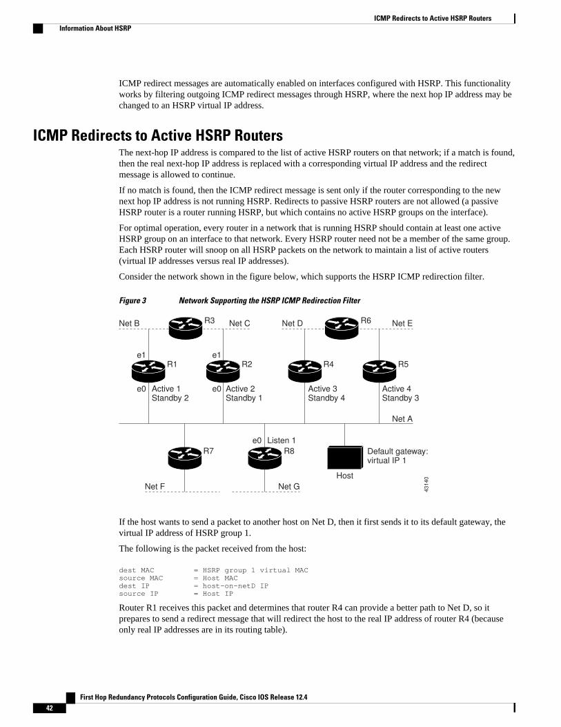
ICMP redirect messages are automatically enabled on interfaces configured with HSRP. This functionalityworks by filtering outgoing ICMP redirect messages through HSRP, where the next hop IP address may bechanged to an HSRP virtual IP address.
ICMP Redirects to Active HSRP RoutersThe next-hop IP address is compared to the list of active HSRP routers on that network; if a match is found,then the real next-hop IP address is replaced with a corresponding virtual IP address and the redirectmessage is allowed to continue.
If no match is found, then the ICMP redirect message is sent only if the router corresponding to the newnext hop IP address is not running HSRP. Redirects to passive HSRP routers are not allowed (a passiveHSRP router is a router running HSRP, but which contains no active HSRP groups on the interface).
For optimal operation, every router in a network that is running HSRP should contain at least one activeHSRP group on an interface to that network. Every HSRP router need not be a member of the same group.Each HSRP router will snoop on all HSRP packets on the network to maintain a list of active routers(virtual IP addresses versus real IP addresses).
Consider the network shown in the figure below, which supports the HSRP ICMP redirection filter.
Figure 3 Network Supporting the HSRP ICMP Redirection Filter
43
14
0
R3Net B
e1
e0
R1
Active 1 Standby 2
e1
e0
R2
Active 2 Standby 1
R7
e0
R8
Listen 1
Host
Net C R6Net D
R4
Active 3 Standby 4
R5
Active 4 Standby 3
Net E
Net A
Net F Net G
Default gateway: virtual IP 1
If the host wants to send a packet to another host on Net D, then it first sends it to its default gateway, thevirtual IP address of HSRP group 1.
The following is the packet received from the host:
dest MAC = HSRP group 1 virtual MACsource MAC = Host MACdest IP = host-on-netD IPsource IP = Host IP
Router R1 receives this packet and determines that router R4 can provide a better path to Net D, so itprepares to send a redirect message that will redirect the host to the real IP address of router R4 (becauseonly real IP addresses are in its routing table).
ICMP Redirects to Active HSRP Routers Information About HSRP
First Hop Redundancy Protocols Configuration Guide, Cisco IOS Release 12.442
The following is the initial ICMP redirect message sent by router R1:
dest MAC = Host MACsource MAC = router R1 MACdest IP = Host IPsource IP = router R1 IPgateway to use = router R4 IP
Before this redirect occurs, the HSRP process of router R1 determines that router R4 is the active HSRProuter for group 3, so it changes the next hop in the redirect message from the real IP address of router R4to the virtual IP address of group 3. Furthermore, it determines from the destination MAC address of thepacket that triggered the redirect message that the host used the virtual IP address of group 1 as its gateway,so it changes the source IP address of the redirect message to the virtual IP address of group 1.
The modified ICMP redirect message showing the two modified fields (*) is as follows:
dest MAC = Host MACsource MAC = router R1 MACdest IP = Host IPsource IP* = HSRP group 1 virtual IPgateway to use* = HSRP group 3 virtual IP
This second modification is necessary because hosts compare the source IP address of the ICMP redirectmessage with their default gateway. If these addresses do not match, the ICMP redirect message is ignored.The routing table of the host now consists of the default gateway, virtual IP address of group 1, and a routeto Net D through the virtual IP address of group 3.
ICMP Redirects to Passive HSRP RoutersICMP redirects to passive HSRP routers are not permitted. Redundancy may be lost if hosts learn the realIP addresses of HSRP routers.
In the "Network Supporting the HSRP ICMP Redirection Filter" figure, redirection to router R8 is notallowed because R8 is a passive HSRP router. In this case, packets from the host to Net D will first go torouter R1 and then be forwarded to router R4; that is, they will traverse the network twice.
A network configuration with passive HSRP routers is considered a misconfiguration. For HSRP ICMPredirection to operate optimally, every router on the network that is running HSRP should contain at leastone active HSRP group.
ICMP Redirects to Non-HSRP RoutersICMP redirects to routers not running HSRP on their local interface are permitted. No redundancy is lost ifhosts learn the real IP address of non-HSRP routers.
In the "Network Supporting the HSRP ICMP Redirection Filter" figure, redirection to router R7 is allowedbecause R7 is not running HSRP. In this case, the next hop IP address is unchanged. The source IP addressis changed dependent upon the destination MAC address of the original packet. You can specify the nostandby redirect unknown command to stop these redirects from being sent.
Passive HSRP Router AdvertisementsPassive HSRP routers send out HSRP advertisement messages both periodically and when entering orleaving the passive state. Thus, all HSRP routers can determine the HSRP group state of any HSRP routeron the network. These advertisements inform other HSRP routers on the network of the HSRP interfacestate, as follows:
ICMP Redirects to Passive HSRP RoutersInformation About HSRP
First Hop Redundancy Protocols Configuration Guide, Cisco IOS Release 12.4 43
• Active—Interface has at least one active group. A single advertisement is sent out when the first groupbecomes active.
• Dormant—Interface has no HSRP groups. A single advertisement is sent once when the last group isremoved.
• Passive—Interface has at least one nonactive group and no active groups. Advertisements are sent outperiodically.
You can adjust the advertisement interval and hold-down time using the standby redirect timerscommand.
ICMP Redirects Not SentIf the HSRP router cannot uniquely determine the IP address used by the host when it sends the packet thatcaused the redirect, the redirect message will not be sent. The router uses the destination MAC address inthe original packet to make this determination. In certain configurations, such as the use of the standbyuse-bia interface configuration command specified on an interface, redirects cannot be sent. In this case,the HSRP groups use the interface MAC address as their virtual MAC address. The router now cannotdetermine if the default gateway of the host is the real IP address or one of the HSRP virtual IP addressesthat are active on the interface.
Using HSRP with ICMP redirects is not possible in the Cisco 800 series, Cisco 1000 series, Cisco 1600series, Cisco 2500 series, Cisco 3000 series, and Cisco 4500 series routers because the Ethernet controllercan support only one MAC address.
The IP source address of an ICMP packet must match the gateway address used by the host in the packetthat triggered the ICMP packet, otherwise the host will reject the ICMP redirect packet. An HSRP routeruses the destination MAC address to determine the gateway IP address of the host. If the HSRP router isusing the same MAC address for multiple IP addresses, uniquely determining the gateway IP address of thehost is not possible, and the redirect message is not sent.
The following is sample output from the debug standby events icmp EXEC command if HSRP could notuniquely determine the gateway used by the host:
10:43:08: HSRP: ICMP redirect not sent to 10.0.0.4 for dest 10.0.1.210:43:08: HSRP: could not uniquely determine IP address for mac 00d0.bbd3.bc22
HSRP Support for MPLS VPNsHSRP support for a Multiprotocol Label Switching (MPLS) VPN interface is useful when an Ethernet LANis connected between two provider edge (PE) routers with either of the following conditions:
• A customer edge (CE) router with a default route to the HSRP virtual IP address• One or more hosts with the HSRP virtual IP address configured as the default gateway
Each VPN is associated with one or more VPN routing and forwarding (VRF) instances. A VRF consists ofthe following elements:
• IP routing table• Cisco Express Forwarding table• Set of interfaces that use the Cisco Express Forwarding forwarding table• Set of rules and routing protocol parameters to control the information in the routing tables
VPN routing information is stored in the IP routing table and the Cisco Express Forwarding table for eachVRF. A separate set of routing and Cisco Express Forwarding tables is maintained for each VRF. These
ICMP Redirects Not Sent Information About HSRP
First Hop Redundancy Protocols Configuration Guide, Cisco IOS Release 12.444
tables prevent information from being forwarded outside a VPN and also prevent packets that are outside aVPN from being forwarded to a router within the VPN.
HSRP adds ARP entries and IP hash table entries (aliases) using the default routing table instance.However, a different routing table instance is used when VRF forwarding is configured on an interface,causing ARP and ICMP echo requests for the HSRP virtual IP address to fail.
HSRP support for MPLS VPNs ensures that the HSRP virtual IP address is added to the correct IP routingtable and not to the default routing table.
HSRP Multiple Group OptimizationThe configuration of many hundreds of subinterfaces on the same physical interface, with each subinterfacehaving its own HSRP group, can cause the processes of negotiation and maintenance of multiple HSRPgroups to have a detrimental impact on network traffic and CPU utilization.
Only one HSRP group is required on a physical interface for the purposes of electing active and standbyrouters. This group is known as the master group. Other HSRP groups may be created on each subinterfaceand linked to the master group via the group name. These linked HSRP groups are known as client or slavegroups.
The HSRP group state of the client groups follows that of the master group. Client groups do not participatein any sort of router election mechanism.
Client groups send periodic messages in order to refresh their virtual MAC addresses in switches andlearning bridges. The refresh message may be sent at a much lower frequency compared with the protocolelection messages sent by the master group.
HSRP--ISSUThe In Service Software Upgrade (ISSU) process allows Cisco IOS software to be updated or otherwisemodified while packet forwarding continues. In most networks, planned software upgrades are a significantcause of downtime. ISSU allows Cisco IOS software to be modified while packet forwarding continues,which increases network availability and reduces downtime caused by planned software upgrades. Thisdocument provides information about ISSU concepts and describes the steps taken to perform ISSU in asystem.
For detailed information about ISSU, see the Cisco IOS In Service Software Upgrade Process document inthe Cisco IOS High Availability Configuration Guide
For detailed information about ISSU on the 7600 series routers, see the ISSU and eFSU on Cisco 7600Series Routers document at the following URL:
http://www.cisco.com/en/US/docs/routers/7600/ios/12.2SR/configuration/guide/efsuovrw.html
For detailed information about ISSU on Cisco Catalyst 4500 series switches, see the “Configuring theCisco IOS In Service Software Upgrade Process” chapter of the Catalyst 4500 Series Switch Cisco IOSSoftware Configuration Guide , Release 12.2(31)SGA at the following URL:
http://www.cisco.com/en/US/docs/switches/lan/catalyst4500/12.2/31sga/configuration/guide/issu.html
SSO HSRPSSO HSRP alters the behavior of HSRP when a router with redundant Route Processors (RPs) isconfigured for stateful switchover (SSO) redundancy mode. When an RP is active and the other RP isstandby, SSO enables the standby RP to take over if the active RP fails.
With this functionality, HSRP SSO information is synchronized to the standby RP, allowing traffic that issent using the HSRP virtual IP address to be continuously forwarded during a switchover without a loss of
HSRP Multiple Group OptimizationInformation About HSRP
First Hop Redundancy Protocols Configuration Guide, Cisco IOS Release 12.4 45
data or a path change. Additionally, if both RPs fail on the active HSRP router, then the standby HSRProuter takes over as the active HSRP router.
The feature is enabled by default when the redundancy mode of operation is set to SSO.
• SSO Dual-Route Processors and Cisco Nonstop Forwarding, page 46• HSRP and SSO Working Together, page 46
SSO Dual-Route Processors and Cisco Nonstop ForwardingSSO functions in networking devices (usually edge devices) that support dual RPs. SSO provides RPredundancy by establishing one of the RPs as the active processor and the other RP as the standbyprocessor. SSO also synchronizes critical state information between the RPs so that network stateinformation is dynamically maintained between RPs.
SSO is generally used with Cisco nonstop forwarding (NSF). Cisco NSF enables forwarding of datapackets to continue along known routes while the routing protocol information is being restored following aswitchover. With NSF, users are less likely to experience service outages.
HSRP and SSO Working TogetherThe SSO HSRP feature enables the Cisco IOS HSRP subsystem software to detect that a standby RP isinstalled and the system is configured in SSO redundancy mode. Further, if the active RP fails, no changeoccurs to the HSRP group itself and traffic continues to be forwarded through the current active gatewayrouter.
Prior to introduction of the SSO HSRP feature, when the primary RP of the active router failed, it wouldstop participating in the HSRP group and trigger another router in the group to take over as the activeHSRP router.
SSO HSRP is required to preserve the forwarding path for traffic destined to the HSRP virtual IP addressthrough an RP switchover.
Configuring SSO on the edge router enables the traffic on the Ethernet links to continue during an RPfailover without the Ethernet traffic switching over to an HSRP standby router (and then back, ifpreemption is enabled).
Note You may want to disable SSO HSRP by using the no standby sso command if you have LAN segmentsthat should switch HSRP traffic to a redundant device while SSO maintains traffic flow for otherconnections.
HSRP BFD PeeringThe HSRP BFD Peering feature introduces BFD in the HSRP group member health monitoring system.HSRP supports BFD as a part of the HSRP group member health monitoring system. Without BFD, HSRPruns as a process in a multiprocess system and cannot be guaranteed to be scheduled in time to service largenumbers of groups with millisecond hello and hold timers. BFD runs as a pseudo-preemptive process andcan therefore be guaranteed to run when required. Only one BFD session between two routers can provideearly failover notification for multiple HSRP groups.
This feature is enabled by default. The HSRP standby router learns the real IP address of the HSRP activerouter from the HSRP Hello messages. The standby router will register as a BFD client and ask to benotified if the active router becomes unavailable.
HSRP BFD Peering SSO Dual-Route Processors and Cisco Nonstop Forwarding
First Hop Redundancy Protocols Configuration Guide, Cisco IOS Release 12.446
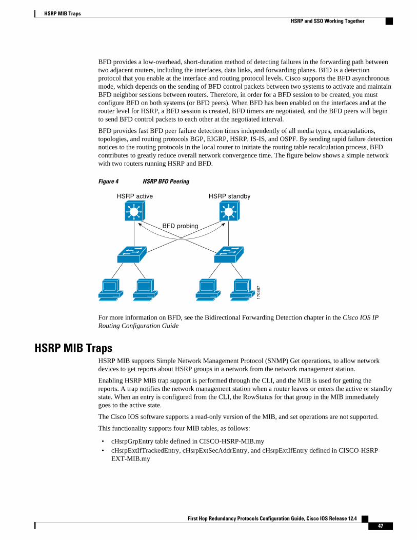
BFD provides a low-overhead, short-duration method of detecting failures in the forwarding path betweentwo adjacent routers, including the interfaces, data links, and forwarding planes. BFD is a detectionprotocol that you enable at the interface and routing protocol levels. Cisco supports the BFD asynchronousmode, which depends on the sending of BFD control packets between two systems to activate and maintainBFD neighbor sessions between routers. Therefore, in order for a BFD session to be created, you mustconfigure BFD on both systems (or BFD peers). When BFD has been enabled on the interfaces and at therouter level for HSRP, a BFD session is created, BFD timers are negotiated, and the BFD peers will beginto send BFD control packets to each other at the negotiated interval.
BFD provides fast BFD peer failure detection times independently of all media types, encapsulations,topologies, and routing protocols BGP, EIGRP, HSRP, IS-IS, and OSPF. By sending rapid failure detectionnotices to the routing protocols in the local router to initiate the routing table recalculation process, BFDcontributes to greatly reduce overall network convergence time. The figure below shows a simple networkwith two routers running HSRP and BFD.
Figure 4 HSRP BFD Peering
BFD probing
HSRP active HSRP standby
17
08
87
For more information on BFD, see the Bidirectional Forwarding Detection chapter in the Cisco IOS IPRouting Configuration Guide
HSRP MIB TrapsHSRP MIB supports Simple Network Management Protocol (SNMP) Get operations, to allow networkdevices to get reports about HSRP groups in a network from the network management station.
Enabling HSRP MIB trap support is performed through the CLI, and the MIB is used for getting thereports. A trap notifies the network management station when a router leaves or enters the active or standbystate. When an entry is configured from the CLI, the RowStatus for that group in the MIB immediatelygoes to the active state.
The Cisco IOS software supports a read-only version of the MIB, and set operations are not supported.
This functionality supports four MIB tables, as follows:
• cHsrpGrpEntry table defined in CISCO-HSRP-MIB.my• cHsrpExtIfTrackedEntry, cHsrpExtSecAddrEntry, and cHsrpExtIfEntry defined in CISCO-HSRP-
EXT-MIB.my
HSRP MIB TrapsHSRP and SSO Working Together
First Hop Redundancy Protocols Configuration Guide, Cisco IOS Release 12.4 47
The cHsrpGrpEntry table consists of all the group information defined in RFC 2281, Cisco Hot StandbyRouter Protocol; the other tables consist of the Cisco extensions to RFC 2281, which are defined inCISCO-HSRP-EXT-MIB.my.
How to Configure HSRP• Enabling HSRP, page 48
• Delaying the Initialization of HSRP on an Interface, page 50
• Configuring HSRP Priority and Preemption, page 53
• Configuring HSRP Object Tracking, page 54
• Configuring HSRP MD5 Authentication Using a Key String, page 57
• Configuring HSRP MD5 Authentication Using a Key Chain, page 59
• Troubleshooting HSRP MD5 Authentication, page 62
• Configuring HSRP Text Authentication, page 64
• Configuring HSRP Timers, page 66
• Configuring an HSRP MAC Refresh Interval, page 67
• Configuring Multiple HSRP Groups for Load Balancing, page 68
• Improving CPU and Network Performance with HSRP Multiple Group Optimization, page 70
• Enabling HSRP Support for ICMP Redirect Messages, page 72
• Configuring HSRP Virtual MAC Addresses or BIA MAC Addresses, page 74
• Linking IP Redundancy Clients to HSRP Groups, page 75
• Changing to HSRP Version 2, page 77
• Enabling SSO Aware HSRP, page 79
• Verifying SSO Aware HSRP, page 80
• Enabling HSRP MIB Traps, page 81
• Configuring BFD Session Parameters on the Interface, page 82
• Configuring HSRP BFD Peering, page 83
• Verifying HSRP BFD Peering, page 85
• Configuring HSRP Gratuitous ARP, page 87
Enabling HSRPPerform this task to enable HSRP.
The standby ip interface configuration command activates HSRP on the configured interface. If an IPaddress is specified, that address is used as the virtual IP address for the Hot Standby group. For HSRP toelect a designated router, you must configure the virtual IP address for at least one of the routers in thegroup; it can be learned on the other routers in the group.
You can configure many attributes in HSRP such as authentication, timers, priority, and preemption. Youshould configure the attributes before enabling the HSRP group. This practice avoids authentication errormessages and unexpected state changes in other routers that can occur if the group is enabled first and thenthere is a long enough delay (one or two hold times) before the other attribues are configured.
We recommend that you always specify an HSRP IP address.
Enabling HSRP How to Configure HSRP
First Hop Redundancy Protocols Configuration Guide, Cisco IOS Release 12.448
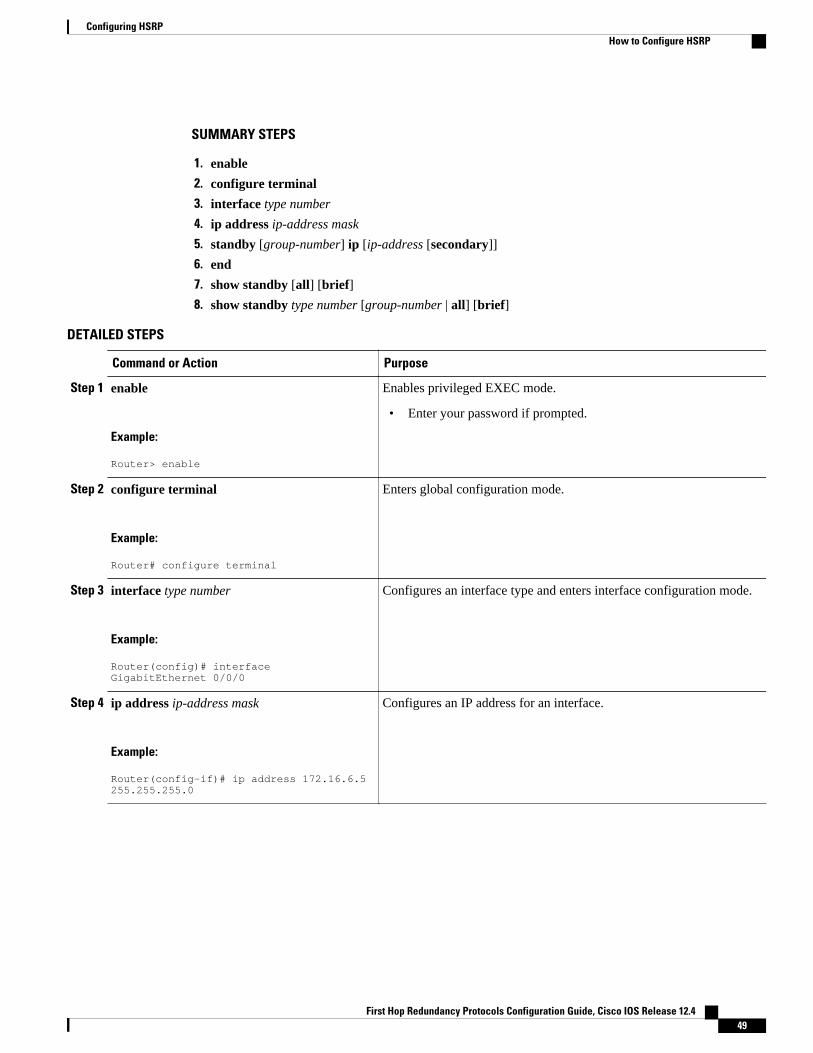
SUMMARY STEPS
1. enable
2. configure terminal
3. interface type number
4. ip address ip-address mask
5. standby [group-number] ip [ip-address [secondary]]
6. end
7. show standby [all] [brief]
8. show standby type number [group-number | all] [brief]
DETAILED STEPS
Command or Action Purpose
Step 1 enable
Example:
Router> enable
Enables privileged EXEC mode.
• Enter your password if prompted.
Step 2 configure terminal
Example:
Router# configure terminal
Enters global configuration mode.
Step 3 interface type number
Example:
Router(config)# interface GigabitEthernet 0/0/0
Configures an interface type and enters interface configuration mode.
Step 4 ip address ip-address mask
Example:
Router(config-if)# ip address 172.16.6.5 255.255.255.0
Configures an IP address for an interface.
Configuring HSRPHow to Configure HSRP
First Hop Redundancy Protocols Configuration Guide, Cisco IOS Release 12.4 49
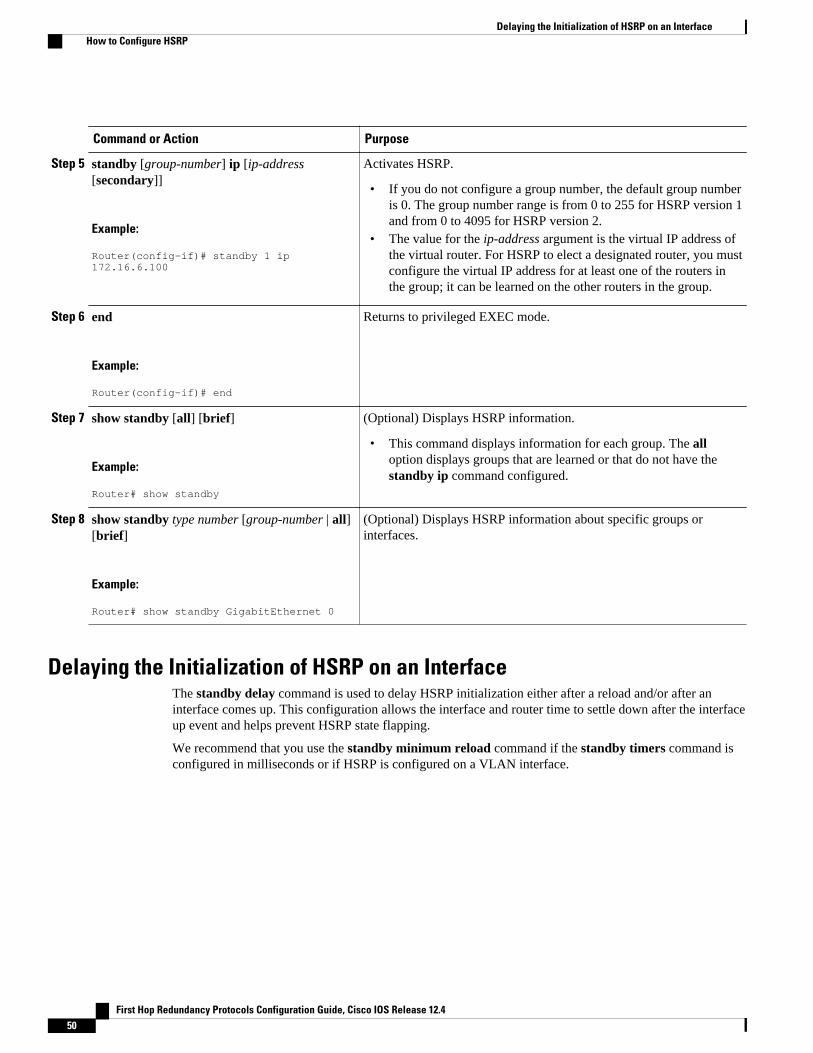
Command or Action Purpose
Step 5 standby [group-number] ip [ip-address[secondary]]
Example:
Router(config-if)# standby 1 ip 172.16.6.100
Activates HSRP.
• If you do not configure a group number, the default group numberis 0. The group number range is from 0 to 255 for HSRP version 1and from 0 to 4095 for HSRP version 2.
• The value for the ip-address argument is the virtual IP address ofthe virtual router. For HSRP to elect a designated router, you mustconfigure the virtual IP address for at least one of the routers inthe group; it can be learned on the other routers in the group.
Step 6 end
Example:
Router(config-if)# end
Returns to privileged EXEC mode.
Step 7 show standby [all] [brief]
Example:
Router# show standby
(Optional) Displays HSRP information.
• This command displays information for each group. The alloption displays groups that are learned or that do not have thestandby ip command configured.
Step 8 show standby type number [group-number | all][brief]
Example:
Router# show standby GigabitEthernet 0
(Optional) Displays HSRP information about specific groups orinterfaces.
Delaying the Initialization of HSRP on an InterfaceThe standby delay command is used to delay HSRP initialization either after a reload and/or after aninterface comes up. This configuration allows the interface and router time to settle down after the interfaceup event and helps prevent HSRP state flapping.
We recommend that you use the standby minimum reload command if the standby timers command isconfigured in milliseconds or if HSRP is configured on a VLAN interface.
Delaying the Initialization of HSRP on an Interface How to Configure HSRP
First Hop Redundancy Protocols Configuration Guide, Cisco IOS Release 12.450

SUMMARY STEPS
1. enable
2. configure terminal
3. interface type number
4. ip address ip-address mask
5. standby delay minimum min-seconds reload reload-seconds
6. standby [group-number ] ip [ip-address [secondary]]
7. end
8. show standby delay [typenumber]
DETAILED STEPS
Command or Action Purpose
Step 1 enable
Example:
Router> enable
Enables privileged EXEC mode.
• Enter your password if prompted.
Step 2 configure terminal
Example:
Router# configure terminal
Enters global configuration mode.
Step 3 interface type number
Example:
Router(config)# interface GigabitEthernet 1/0/0
Configures an interface type and enters interface configurationmode.
Step 4 ip address ip-address mask
Example:
Router(config-if)# ip address 10.0.0.1 255.255.255.0
Specifies an IP address for an interface.
Configuring HSRPHow to Configure HSRP
First Hop Redundancy Protocols Configuration Guide, Cisco IOS Release 12.4 51
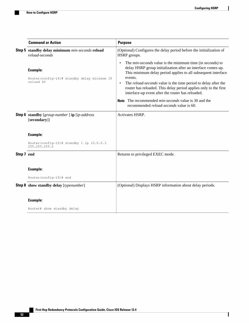
Command or Action Purpose
Step 5 standby delay minimum min-seconds reloadreload-seconds
Example:
Router(config-if)# standby delay minimum 30 reload 60
(Optional) Configures the delay period before the initialization ofHSRP groups.
• The min-seconds value is the minimum time (in seconds) todelay HSRP group initialization after an interface comes up.This minimum delay period applies to all subsequent interfaceevents.
• The reload-seconds value is the time period to delay after therouter has reloaded. This delay period applies only to the firstinterface-up event after the router has reloaded.
Note The recommended min-seconds value is 30 and therecommended reload-seconds value is 60.
Step 6 standby [group-number ] ip [ip-address[secondary]]
Example:
Router(config-if)# standby 1 ip 10.0.0.3 255.255.255.0
Activates HSRP.
Step 7 end
Example:
Router(config-if)# end
Returns to privileged EXEC mode.
Step 8 show standby delay [typenumber]
Example:
Router# show standby delay
(Optional) Displays HSRP information about delay periods.
Configuring HSRP How to Configure HSRP
First Hop Redundancy Protocols Configuration Guide, Cisco IOS Release 12.452
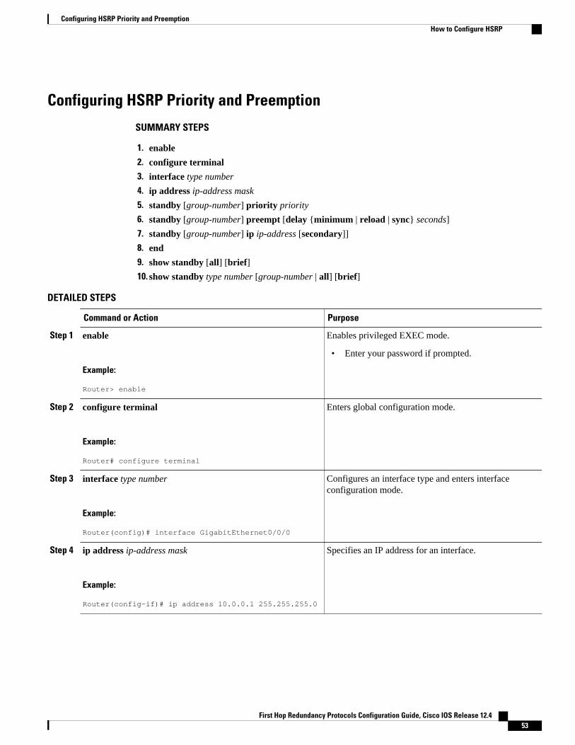
Configuring HSRP Priority and Preemption
SUMMARY STEPS
1. enable
2. configure terminal
3. interface type number
4. ip address ip-address mask
5. standby [group-number] priority priority
6. standby [group-number] preempt [delay {minimum | reload | sync} seconds]
7. standby [group-number] ip ip-address [secondary]]
8. end
9. show standby [all] [brief]
10. show standby type number [group-number | all] [brief]
DETAILED STEPS
Command or Action Purpose
Step 1 enable
Example:
Router> enable
Enables privileged EXEC mode.
• Enter your password if prompted.
Step 2 configure terminal
Example:
Router# configure terminal
Enters global configuration mode.
Step 3 interface type number
Example:
Router(config)# interface GigabitEthernet0/0/0
Configures an interface type and enters interfaceconfiguration mode.
Step 4 ip address ip-address mask
Example:
Router(config-if)# ip address 10.0.0.1 255.255.255.0
Specifies an IP address for an interface.
Configuring HSRP Priority and PreemptionHow to Configure HSRP
First Hop Redundancy Protocols Configuration Guide, Cisco IOS Release 12.4 53
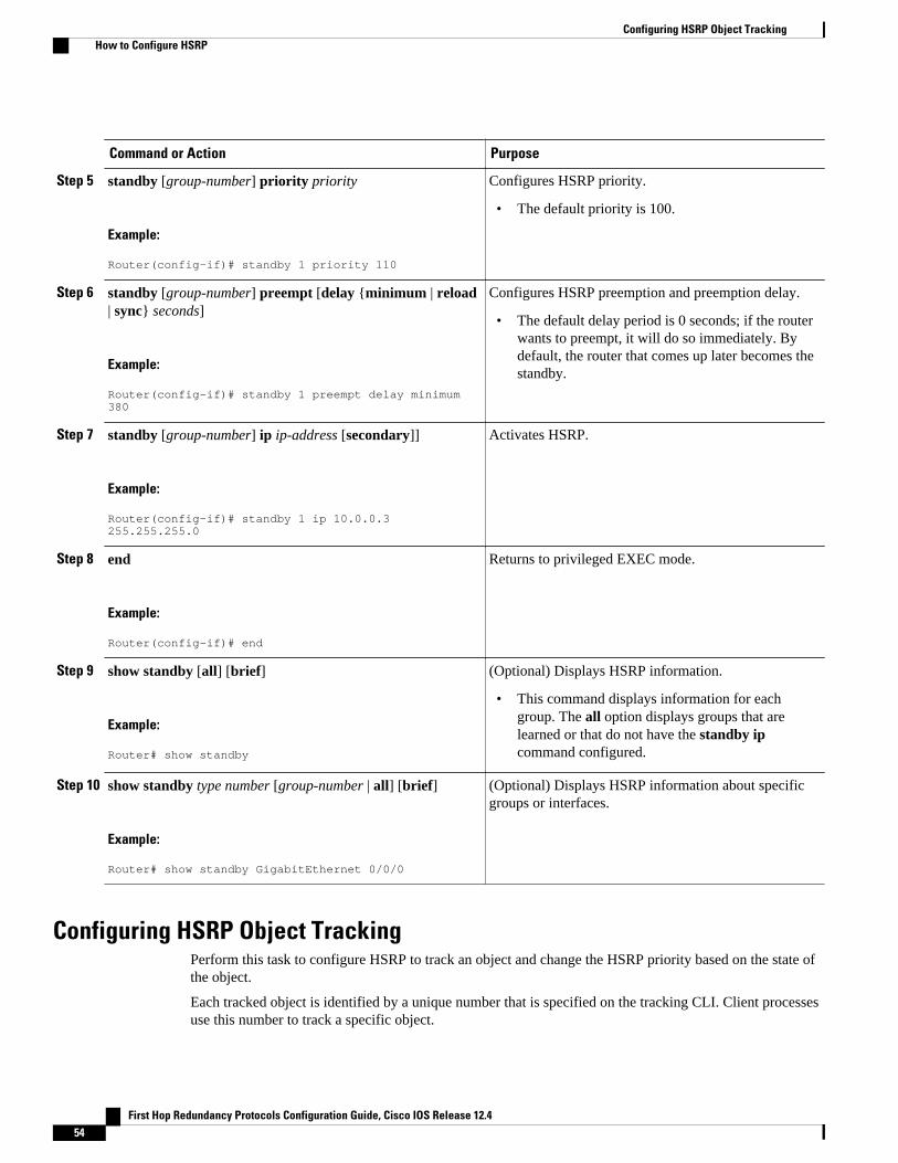
Command or Action Purpose
Step 5 standby [group-number] priority priority
Example:
Router(config-if)# standby 1 priority 110
Configures HSRP priority.
• The default priority is 100.
Step 6 standby [group-number] preempt [delay {minimum | reload| sync} seconds]
Example:
Router(config-if)# standby 1 preempt delay minimum 380
Configures HSRP preemption and preemption delay.
• The default delay period is 0 seconds; if the routerwants to preempt, it will do so immediately. Bydefault, the router that comes up later becomes thestandby.
Step 7 standby [group-number] ip ip-address [secondary]]
Example:
Router(config-if)# standby 1 ip 10.0.0.3 255.255.255.0
Activates HSRP.
Step 8 end
Example:
Router(config-if)# end
Returns to privileged EXEC mode.
Step 9 show standby [all] [brief]
Example:
Router# show standby
(Optional) Displays HSRP information.
• This command displays information for eachgroup. The all option displays groups that arelearned or that do not have the standby ipcommand configured.
Step 10 show standby type number [group-number | all] [brief]
Example:
Router# show standby GigabitEthernet 0/0/0
(Optional) Displays HSRP information about specificgroups or interfaces.
Configuring HSRP Object TrackingPerform this task to configure HSRP to track an object and change the HSRP priority based on the state ofthe object.
Each tracked object is identified by a unique number that is specified on the tracking CLI. Client processesuse this number to track a specific object.
Configuring HSRP Object Tracking How to Configure HSRP
First Hop Redundancy Protocols Configuration Guide, Cisco IOS Release 12.454

SUMMARY STEPS
1. enable
2. configure terminal
3. track object-number interface type number {line-protocol | ip routing}
4. exit
5. interface type number
6. standby [group-number] track object-number [decrement priority-decrement] [shutdown]
7. standby [group-number] ip [ip-address [secondary]]
8. end
9. show track [object-number | brief] [interface [brief] | ip route [brief] | resolution | timers]
DETAILED STEPS
Command or Action Purpose
Step 1 enable
Example:
Router> enable
Enables privileged EXEC mode.
• Enter your password if prompted.
Step 2 configure terminal
Example:
Router# configure terminal
Enters global configuration mode.
Step 3 track object-number interface type number {line-protocol | ip routing}
Example:
Router(config)# track 100 interface GigabitEthernet 0/0/0 line-protocol
Configures an interface to be tracked and enters trackingconfiguration mode.
Step 4 exit
Example:
Router(config-track)# exit
Returns to global configuration mode.
Configuring HSRPHow to Configure HSRP
First Hop Redundancy Protocols Configuration Guide, Cisco IOS Release 12.4 55
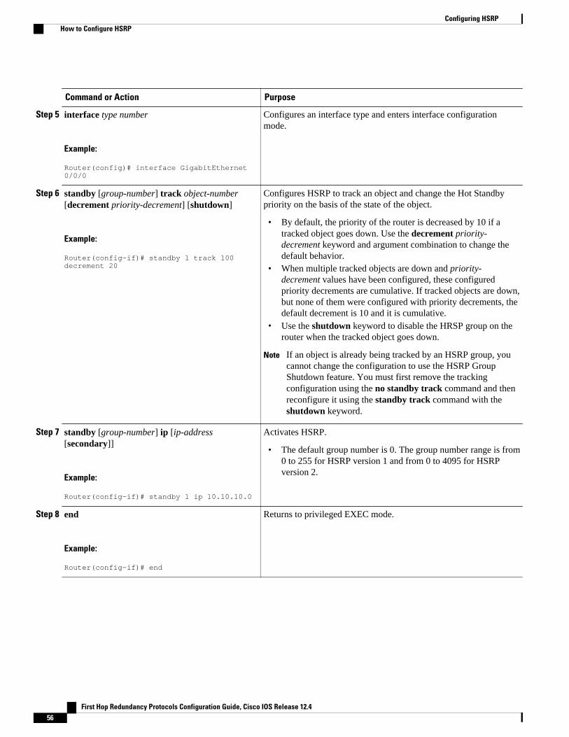
Command or Action Purpose
Step 5 interface type number
Example:
Router(config)# interface GigabitEthernet 0/0/0
Configures an interface type and enters interface configurationmode.
Step 6 standby [group-number] track object-number[decrement priority-decrement] [shutdown]
Example:
Router(config-if)# standby 1 track 100 decrement 20
Configures HSRP to track an object and change the Hot Standbypriority on the basis of the state of the object.
• By default, the priority of the router is decreased by 10 if atracked object goes down. Use the decrement priority-decrement keyword and argument combination to change thedefault behavior.
• When multiple tracked objects are down and priority-decrement values have been configured, these configuredpriority decrements are cumulative. If tracked objects are down,but none of them were configured with priority decrements, thedefault decrement is 10 and it is cumulative.
• Use the shutdown keyword to disable the HRSP group on therouter when the tracked object goes down.
Note If an object is already being tracked by an HSRP group, youcannot change the configuration to use the HSRP GroupShutdown feature. You must first remove the trackingconfiguration using the no standby track command and thenreconfigure it using the standby track command with theshutdown keyword.
Step 7 standby [group-number] ip [ip-address[secondary]]
Example:
Router(config-if)# standby 1 ip 10.10.10.0
Activates HSRP.
• The default group number is 0. The group number range is from0 to 255 for HSRP version 1 and from 0 to 4095 for HSRPversion 2.
Step 8 end
Example:
Router(config-if)# end
Returns to privileged EXEC mode.
Configuring HSRP How to Configure HSRP
First Hop Redundancy Protocols Configuration Guide, Cisco IOS Release 12.456
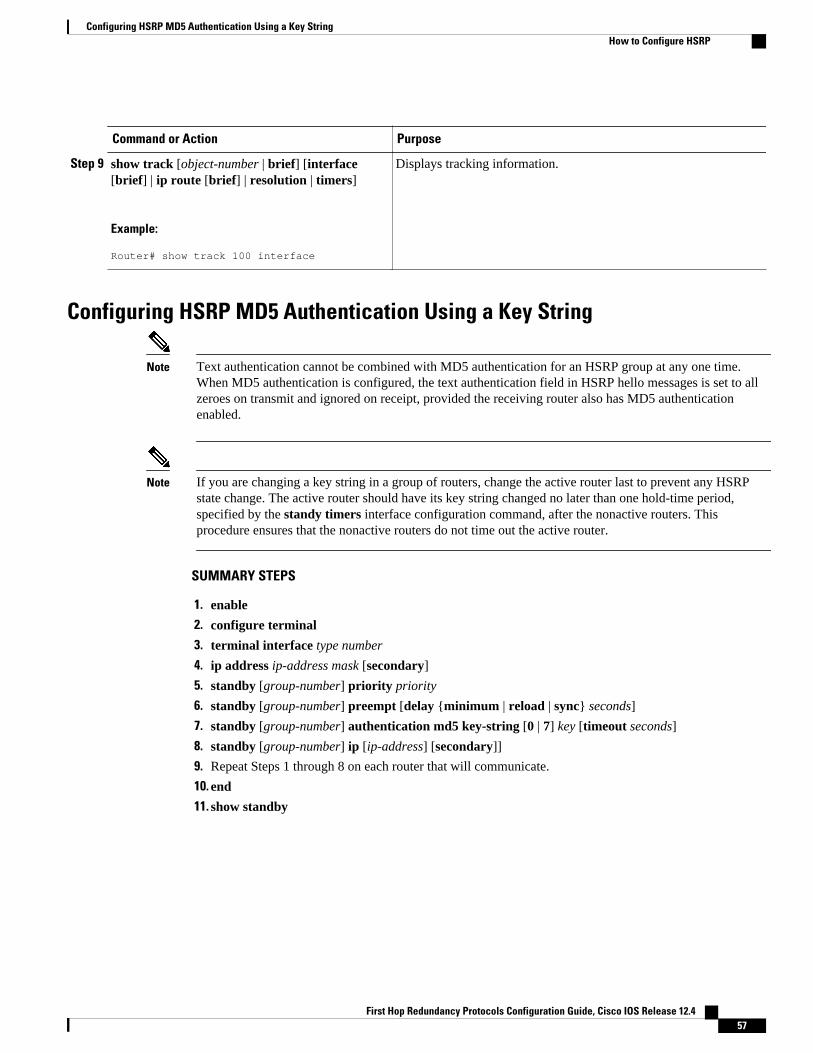
Command or Action Purpose
Step 9 show track [object-number | brief] [interface[brief] | ip route [brief] | resolution | timers]
Example:
Router# show track 100 interface
Displays tracking information.
Configuring HSRP MD5 Authentication Using a Key String
Note Text authentication cannot be combined with MD5 authentication for an HSRP group at any one time.When MD5 authentication is configured, the text authentication field in HSRP hello messages is set to allzeroes on transmit and ignored on receipt, provided the receiving router also has MD5 authenticationenabled.
Note If you are changing a key string in a group of routers, change the active router last to prevent any HSRPstate change. The active router should have its key string changed no later than one hold-time period,specified by the standy timers interface configuration command, after the nonactive routers. Thisprocedure ensures that the nonactive routers do not time out the active router.
SUMMARY STEPS
1. enable
2. configure terminal
3. terminal interface type number
4. ip address ip-address mask [secondary]
5. standby [group-number] priority priority
6. standby [group-number] preempt [delay {minimum | reload | sync} seconds]
7. standby [group-number] authentication md5 key-string [0 | 7] key [timeout seconds]
8. standby [group-number] ip [ip-address] [secondary]]
9. Repeat Steps 1 through 8 on each router that will communicate.
10. end
11. show standby
Configuring HSRP MD5 Authentication Using a Key StringHow to Configure HSRP
First Hop Redundancy Protocols Configuration Guide, Cisco IOS Release 12.4 57
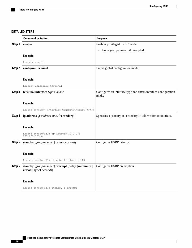
DETAILED STEPS
Command or Action Purpose
Step 1 enable
Example:
Router> enable
Enables privileged EXEC mode.
• Enter your password if prompted.
Step 2 configure terminal
Example:
Router# configure terminal
Enters global configuration mode.
Step 3 terminal interface type number
Example:
Router(config)# interface GigabitEthernet 0/0/0
Configures an interface type and enters interface configurationmode.
Step 4 ip address ip-address mask [secondary]
Example:
Router(config-if)# ip address 10.0.0.1 255.255.255.0
Specifies a primary or secondary IP address for an interface.
Step 5 standby [group-number] priority priority
Example:
Router(config-if)# standby 1 priority 110
Configures HSRP priority.
Step 6 standby [group-number] preempt [delay {minimum |reload | sync} seconds]
Example:
Router(config-if)# standby 1 preempt
Configures HSRP preemption.
Configuring HSRP How to Configure HSRP
First Hop Redundancy Protocols Configuration Guide, Cisco IOS Release 12.458
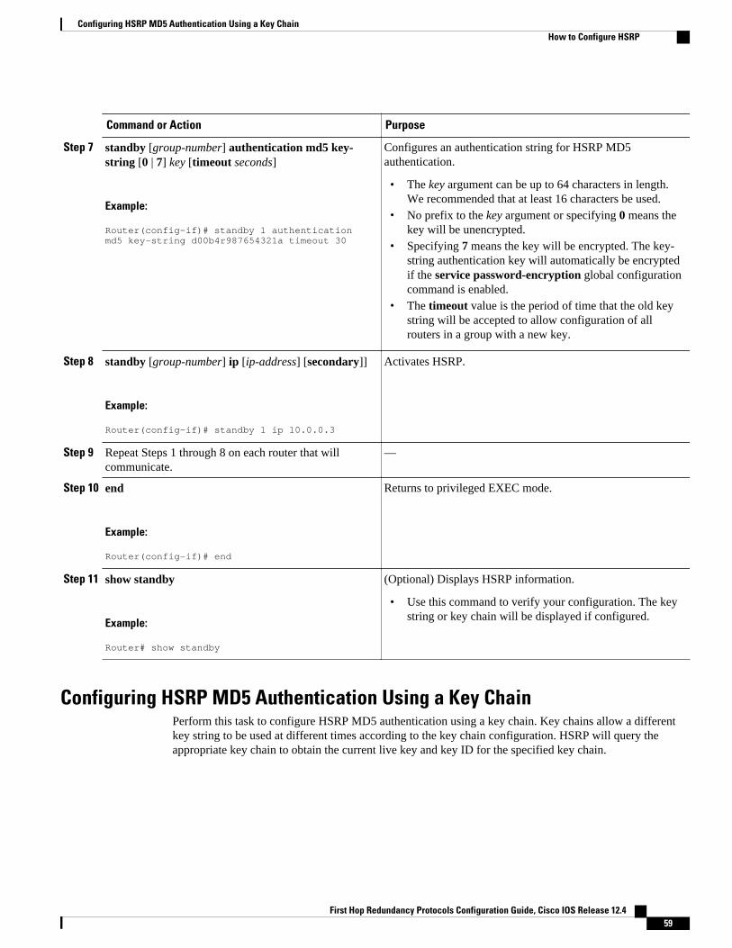
Command or Action Purpose
Step 7 standby [group-number] authentication md5 key-string [0 | 7] key [timeout seconds]
Example:
Router(config-if)# standby 1 authentication md5 key-string d00b4r987654321a timeout 30
Configures an authentication string for HSRP MD5authentication.
• The key argument can be up to 64 characters in length.We recommended that at least 16 characters be used.
• No prefix to the key argument or specifying 0 means thekey will be unencrypted.
• Specifying 7 means the key will be encrypted. The key-string authentication key will automatically be encryptedif the service password-encryption global configurationcommand is enabled.
• The timeout value is the period of time that the old keystring will be accepted to allow configuration of allrouters in a group with a new key.
Step 8 standby [group-number] ip [ip-address] [secondary]]
Example:
Router(config-if)# standby 1 ip 10.0.0.3
Activates HSRP.
Step 9 Repeat Steps 1 through 8 on each router that willcommunicate.
—
Step 10 end
Example:
Router(config-if)# end
Returns to privileged EXEC mode.
Step 11 show standby
Example:
Router# show standby
(Optional) Displays HSRP information.
• Use this command to verify your configuration. The keystring or key chain will be displayed if configured.
Configuring HSRP MD5 Authentication Using a Key ChainPerform this task to configure HSRP MD5 authentication using a key chain. Key chains allow a differentkey string to be used at different times according to the key chain configuration. HSRP will query theappropriate key chain to obtain the current live key and key ID for the specified key chain.
Configuring HSRP MD5 Authentication Using a Key ChainHow to Configure HSRP
First Hop Redundancy Protocols Configuration Guide, Cisco IOS Release 12.4 59
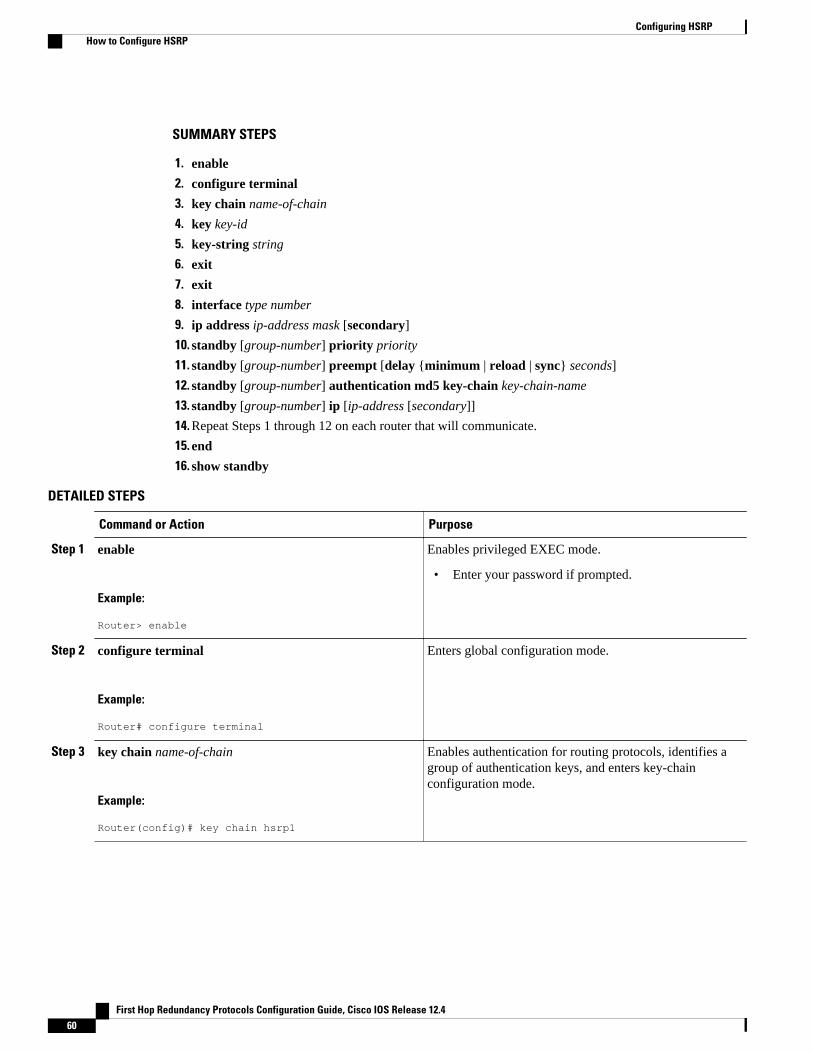
SUMMARY STEPS
1. enable
2. configure terminal
3. key chain name-of-chain
4. key key-id
5. key-string string
6. exit
7. exit
8. interface type number
9. ip address ip-address mask [secondary]
10. standby [group-number] priority priority
11. standby [group-number] preempt [delay {minimum | reload | sync} seconds]
12. standby [group-number] authentication md5 key-chain key-chain-name
13. standby [group-number] ip [ip-address [secondary]]
14. Repeat Steps 1 through 12 on each router that will communicate.
15. end
16. show standby
DETAILED STEPS
Command or Action Purpose
Step 1 enable
Example:
Router> enable
Enables privileged EXEC mode.
• Enter your password if prompted.
Step 2 configure terminal
Example:
Router# configure terminal
Enters global configuration mode.
Step 3 key chain name-of-chain
Example:
Router(config)# key chain hsrp1
Enables authentication for routing protocols, identifies agroup of authentication keys, and enters key-chainconfiguration mode.
Configuring HSRP How to Configure HSRP
First Hop Redundancy Protocols Configuration Guide, Cisco IOS Release 12.460
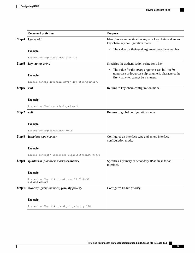
Command or Action Purpose
Step 4 key key-id
Example:
Router(config-keychain)# key 100
Identifies an authentication key on a key chain and enterskey-chain key configuration mode.
• The value for thekey-id argument must be a number.
Step 5 key-string string
Example:
Router(config-keychain-key)# key-string mno172
Specifies the authentication string for a key.
• The value for the string argument can be 1 to 80uppercase or lowercase alphanumeric characters; thefirst character cannot be a numeral
Step 6 exit
Example:
Router(config-keychain-key)# exit
Returns to key-chain configuration mode.
Step 7 exit
Example:
Router(config-keychain)# exit
Returns to global configuration mode.
Step 8 interface type number
Example:
Router(config)# interface GigabitEthernet 0/0/0
Configures an interface type and enters interfaceconfiguration mode.
Step 9 ip address ip-address mask [secondary]
Example:
Router(config-if)# ip address 10.21.8.32 255.255.255.0
Specifies a primary or secondary IP address for aninterface.
Step 10 standby [group-number] priority priority
Example:
Router(config-if)# standby 1 priority 110
Configures HSRP priority.
Configuring HSRPHow to Configure HSRP
First Hop Redundancy Protocols Configuration Guide, Cisco IOS Release 12.4 61
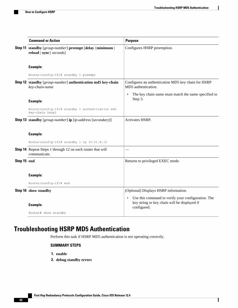
Command or Action Purpose
Step 11 standby [group-number] preempt [delay {minimum |reload | sync} seconds]
Example:
Router(config-if)# standby 1 preempt
Configures HSRP preemption.
Step 12 standby [group-number] authentication md5 key-chainkey-chain-name
Example:
Router(config-if)# standby 1 authentication md5 key-chain hsrp1
Configures an authentication MD5 key chain for HSRPMD5 authentication.
• The key chain name must match the name specified inStep 3.
Step 13 standby [group-number] ip [ip-address [secondary]]
Example:
Router(config-if)# standby 1 ip 10.21.8.12
Activates HSRP.
Step 14 Repeat Steps 1 through 12 on each router that willcommunicate.
—
Step 15 end
Example:
Router(config-if)# end
Returns to privileged EXEC mode.
Step 16 show standby
Example:
Router# show standby
(Optional) Displays HSRP information.
• Use this command to verify your configuration. Thekey string or key chain will be displayed ifconfigured.
Troubleshooting HSRP MD5 AuthenticationPerform this task if HSRP MD5 authentication is not operating correctly.
SUMMARY STEPS
1. enable
2. debug standby errors
Troubleshooting HSRP MD5 Authentication How to Configure HSRP
First Hop Redundancy Protocols Configuration Guide, Cisco IOS Release 12.462
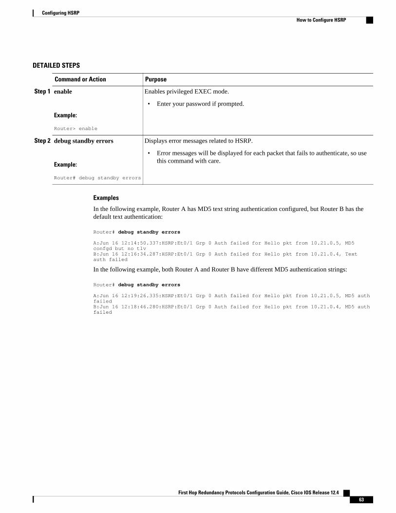
DETAILED STEPS
Command or Action Purpose
Step 1 enable
Example:
Router> enable
Enables privileged EXEC mode.
• Enter your password if prompted.
Step 2 debug standby errors
Example:
Router# debug standby errors
Displays error messages related to HSRP.
• Error messages will be displayed for each packet that fails to authenticate, so usethis command with care.
Examples
In the following example, Router A has MD5 text string authentication configured, but Router B has thedefault text authentication:
Router# debug standby errors
A:Jun 16 12:14:50.337:HSRP:Et0/1 Grp 0 Auth failed for Hello pkt from 10.21.0.5, MD5 confgd but no tlvB:Jun 16 12:16:34.287:HSRP:Et0/1 Grp 0 Auth failed for Hello pkt from 10.21.0.4, Text auth failed
In the following example, both Router A and Router B have different MD5 authentication strings:
Router# debug standby errors
A:Jun 16 12:19:26.335:HSRP:Et0/1 Grp 0 Auth failed for Hello pkt from 10.21.0.5, MD5 auth failedB:Jun 16 12:18:46.280:HSRP:Et0/1 Grp 0 Auth failed for Hello pkt from 10.21.0.4, MD5 auth failed
Configuring HSRPHow to Configure HSRP
First Hop Redundancy Protocols Configuration Guide, Cisco IOS Release 12.4 63
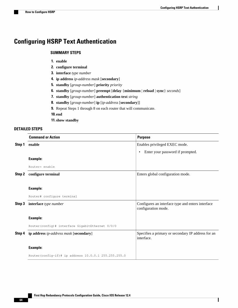
Configuring HSRP Text Authentication
SUMMARY STEPS
1. enable
2. configure terminal
3. interface type number
4. ip address ip-address mask [secondary]
5. standby [group-number] priority priority
6. standby [group-number] preempt [delay {minimum | reload | sync} seconds]
7. standby [group-number] authentication text string
8. standby [group-number] ip [ip-address [secondary]]
9. Repeat Steps 1 through 8 on each router that will communicate.
10. end
11. show standby
DETAILED STEPS
Command or Action Purpose
Step 1 enable
Example:
Router> enable
Enables privileged EXEC mode.
• Enter your password if prompted.
Step 2 configure terminal
Example:
Router# configure terminal
Enters global configuration mode.
Step 3 interface type number
Example:
Router(config)# interface GigabitEthernet 0/0/0
Configures an interface type and enters interfaceconfiguration mode.
Step 4 ip address ip-address mask [secondary]
Example:
Router(config-if)# ip address 10.0.0.1 255.255.255.0
Specifies a primary or secondary IP address for aninterface.
Configuring HSRP Text Authentication How to Configure HSRP
First Hop Redundancy Protocols Configuration Guide, Cisco IOS Release 12.464
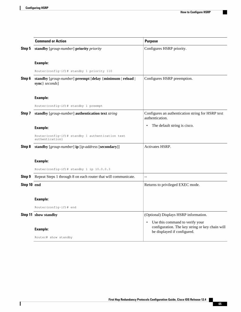
Command or Action Purpose
Step 5 standby [group-number] priority priority
Example:
Router(config-if)# standby 1 priority 110
Configures HSRP priority.
Step 6 standby [group-number] preempt [delay {minimum | reload |sync} seconds]
Example:
Router(config-if)# standby 1 preempt
Configures HSRP preemption.
Step 7 standby [group-number] authentication text string
Example:
Router(config-if)# standby 1 authentication text authentication1
Configures an authentication string for HSRP textauthentication.
• The default string is cisco.
Step 8 standby [group-number] ip [ip-address [secondary]]
Example:
Router(config-if)# standby 1 ip 10.0.0.3
Activates HSRP.
Step 9 Repeat Steps 1 through 8 on each router that will communicate. --
Step 10 end
Example:
Router(config-if)# end
Returns to privileged EXEC mode.
Step 11 show standby
Example:
Router# show standby
(Optional) Displays HSRP information.
• Use this command to verify yourconfiguration. The key string or key chain willbe displayed if configured.
Configuring HSRPHow to Configure HSRP
First Hop Redundancy Protocols Configuration Guide, Cisco IOS Release 12.4 65
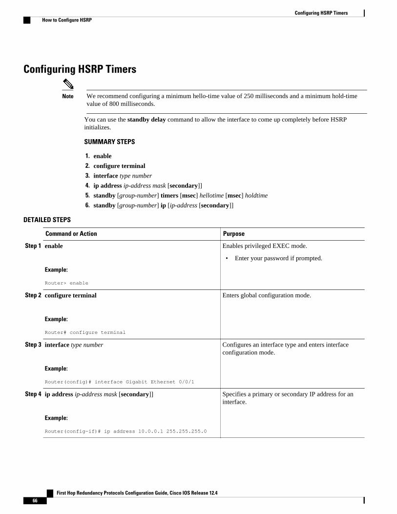
Configuring HSRP Timers
Note We recommend configuring a minimum hello-time value of 250 milliseconds and a minimum hold-timevalue of 800 milliseconds.
You can use the standby delay command to allow the interface to come up completely before HSRPinitializes.
SUMMARY STEPS
1. enable
2. configure terminal
3. interface type number
4. ip address ip-address mask [secondary]]
5. standby [group-number] timers [msec] hellotime [msec] holdtime
6. standby [group-number] ip [ip-address [secondary]]
DETAILED STEPS
Command or Action Purpose
Step 1 enable
Example:
Router> enable
Enables privileged EXEC mode.
• Enter your password if prompted.
Step 2 configure terminal
Example:
Router# configure terminal
Enters global configuration mode.
Step 3 interface type number
Example:
Router(config)# interface Gigabit Ethernet 0/0/1
Configures an interface type and enters interfaceconfiguration mode.
Step 4 ip address ip-address mask [secondary]]
Example:
Router(config-if)# ip address 10.0.0.1 255.255.255.0
Specifies a primary or secondary IP address for aninterface.
Configuring HSRP Timers How to Configure HSRP
First Hop Redundancy Protocols Configuration Guide, Cisco IOS Release 12.466
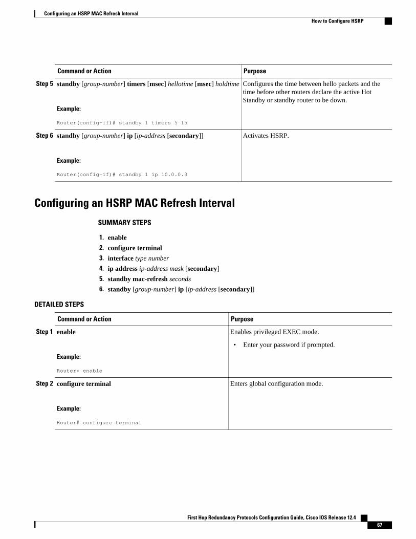
Command or Action Purpose
Step 5 standby [group-number] timers [msec] hellotime [msec] holdtime
Example:
Router(config-if)# standby 1 timers 5 15
Configures the time between hello packets and thetime before other routers declare the active HotStandby or standby router to be down.
Step 6 standby [group-number] ip [ip-address [secondary]]
Example:
Router(config-if)# standby 1 ip 10.0.0.3
Activates HSRP.
Configuring an HSRP MAC Refresh Interval
SUMMARY STEPS
1. enable
2. configure terminal
3. interface type number
4. ip address ip-address mask [secondary]
5. standby mac-refresh seconds
6. standby [group-number] ip [ip-address [secondary]]
DETAILED STEPS
Command or Action Purpose
Step 1 enable
Example:
Router> enable
Enables privileged EXEC mode.
• Enter your password if prompted.
Step 2 configure terminal
Example:
Router# configure terminal
Enters global configuration mode.
Configuring an HSRP MAC Refresh IntervalHow to Configure HSRP
First Hop Redundancy Protocols Configuration Guide, Cisco IOS Release 12.4 67
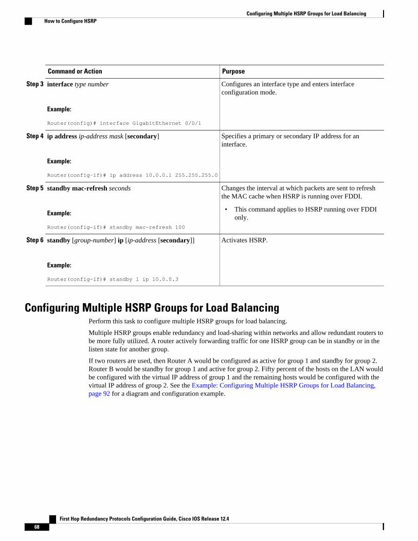
Command or Action Purpose
Step 3 interface type number
Example:
Router(config)# interface GigabitEthernet 0/0/1
Configures an interface type and enters interfaceconfiguration mode.
Step 4 ip address ip-address mask [secondary]
Example:
Router(config-if)# ip address 10.0.0.1 255.255.255.0
Specifies a primary or secondary IP address for aninterface.
Step 5 standby mac-refresh seconds
Example:
Router(config-if)# standby mac-refresh 100
Changes the interval at which packets are sent to refreshthe MAC cache when HSRP is running over FDDI.
• This command applies to HSRP running over FDDIonly.
Step 6 standby [group-number] ip [ip-address [secondary]]
Example:
Router(config-if)# standby 1 ip 10.0.0.3
Activates HSRP.
Configuring Multiple HSRP Groups for Load BalancingPerform this task to configure multiple HSRP groups for load balancing.
Multiple HSRP groups enable redundancy and load-sharing within networks and allow redundant routers tobe more fully utilized. A router actively forwarding traffic for one HSRP group can be in standby or in thelisten state for another group.
If two routers are used, then Router A would be configured as active for group 1 and standby for group 2.Router B would be standby for group 1 and active for group 2. Fifty percent of the hosts on the LAN wouldbe configured with the virtual IP address of group 1 and the remaining hosts would be configured with thevirtual IP address of group 2. See the Example: Configuring Multiple HSRP Groups for Load Balancing, page 92 for a diagram and configuration example.
Configuring Multiple HSRP Groups for Load Balancing How to Configure HSRP
First Hop Redundancy Protocols Configuration Guide, Cisco IOS Release 12.468
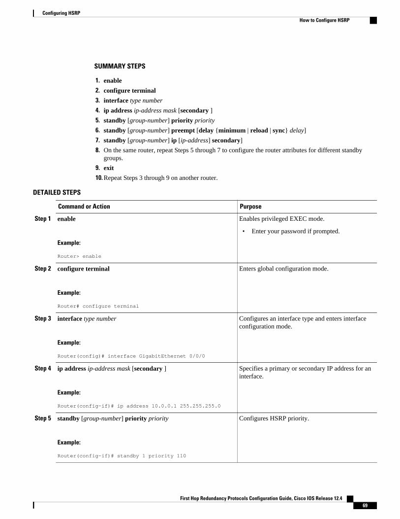
SUMMARY STEPS
1. enable
2. configure terminal
3. interface type number
4. ip address ip-address mask [secondary ]
5. standby [group-number] priority priority
6. standby [group-number] preempt [delay {minimum | reload | sync} delay]
7. standby [group-number] ip [ip-address] secondary]
8. On the same router, repeat Steps 5 through 7 to configure the router attributes for different standbygroups.
9. exit
10. Repeat Steps 3 through 9 on another router.
DETAILED STEPS
Command or Action Purpose
Step 1 enable
Example:
Router> enable
Enables privileged EXEC mode.
• Enter your password if prompted.
Step 2 configure terminal
Example:
Router# configure terminal
Enters global configuration mode.
Step 3 interface type number
Example:
Router(config)# interface GigabitEthernet 0/0/0
Configures an interface type and enters interfaceconfiguration mode.
Step 4 ip address ip-address mask [secondary ]
Example:
Router(config-if)# ip address 10.0.0.1 255.255.255.0
Specifies a primary or secondary IP address for aninterface.
Step 5 standby [group-number] priority priority
Example:
Router(config-if)# standby 1 priority 110
Configures HSRP priority.
Configuring HSRPHow to Configure HSRP
First Hop Redundancy Protocols Configuration Guide, Cisco IOS Release 12.4 69
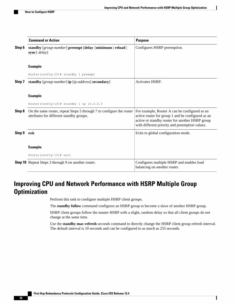
Command or Action Purpose
Step 6 standby [group-number] preempt [delay {minimum | reload |sync} delay]
Example:
Router(config-if)# standby 1 preempt
Configures HSRP preemption.
Step 7 standby [group-number] ip [ip-address] secondary]
Example:
Router(config-if)# standby 1 ip 10.0.0.3
Activates HSRP.
Step 8 On the same router, repeat Steps 5 through 7 to configure the routerattributes for different standby groups.
For example, Router A can be configured as anactive router for group 1 and be configured as anactive or standby router for another HSRP groupwith different priority and preemption values.
Step 9 exit
Example:
Router(config-if)# exit
Exits to global configuration mode.
Step 10 Repeat Steps 3 through 9 on another router. Configures multiple HSRP and enables loadbalancing on another router.
Improving CPU and Network Performance with HSRP Multiple GroupOptimization
Perform this task to configure multiple HSRP client groups.
The standby follow command configures an HSRP group to become a slave of another HSRP group.
HSRP client groups follow the master HSRP with a slight, random delay so that all client groups do notchange at the same time.
Use the standby mac-refresh seconds command to directly change the HSRP client group refresh interval.The default interval is 10 seconds and can be configured to as much as 255 seconds.
Improving CPU and Network Performance with HSRP Multiple Group Optimization How to Configure HSRP
First Hop Redundancy Protocols Configuration Guide, Cisco IOS Release 12.470
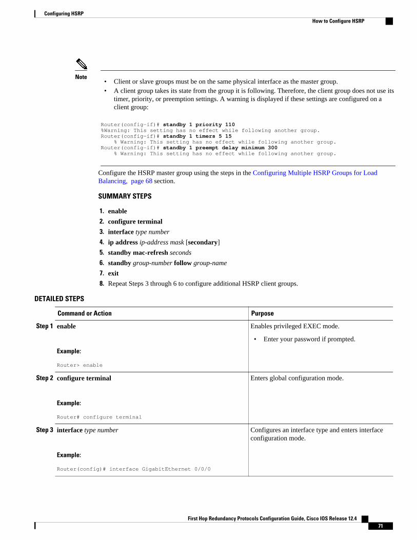
Note• Client or slave groups must be on the same physical interface as the master group.• A client group takes its state from the group it is following. Therefore, the client group does not use its
timer, priority, or preemption settings. A warning is displayed if these settings are configured on aclient group:
Router(config-if)# standby 1 priority 110%Warning: This setting has no effect while following another group.Router(config-if)# standby 1 timers 5 15 % Warning: This setting has no effect while following another group.Router(config-if)# standby 1 preempt delay minimum 300 % Warning: This setting has no effect while following another group.
Configure the HSRP master group using the steps in the Configuring Multiple HSRP Groups for LoadBalancing, page 68 section.
SUMMARY STEPS
1. enable
2. configure terminal
3. interface type number
4. ip address ip-address mask [secondary]
5. standby mac-refresh seconds
6. standby group-number follow group-name
7. exit
8. Repeat Steps 3 through 6 to configure additional HSRP client groups.
DETAILED STEPS
Command or Action Purpose
Step 1 enable
Example:
Router> enable
Enables privileged EXEC mode.
• Enter your password if prompted.
Step 2 configure terminal
Example:
Router# configure terminal
Enters global configuration mode.
Step 3 interface type number
Example:
Router(config)# interface GigabitEthernet 0/0/0
Configures an interface type and enters interfaceconfiguration mode.
Configuring HSRPHow to Configure HSRP
First Hop Redundancy Protocols Configuration Guide, Cisco IOS Release 12.4 71
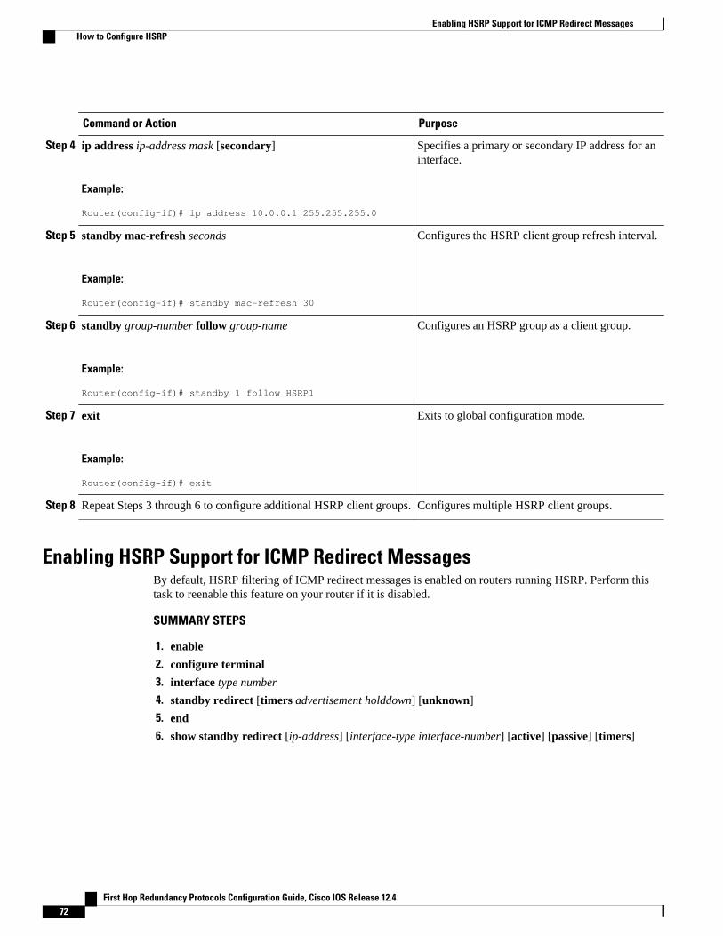
Command or Action Purpose
Step 4 ip address ip-address mask [secondary]
Example:
Router(config-if)# ip address 10.0.0.1 255.255.255.0
Specifies a primary or secondary IP address for aninterface.
Step 5 standby mac-refresh seconds
Example:
Router(config-if)# standby mac-refresh 30
Configures the HSRP client group refresh interval.
Step 6 standby group-number follow group-name
Example:
Router(config-if)# standby 1 follow HSRP1
Configures an HSRP group as a client group.
Step 7 exit
Example:
Router(config-if)# exit
Exits to global configuration mode.
Step 8 Repeat Steps 3 through 6 to configure additional HSRP client groups. Configures multiple HSRP client groups.
Enabling HSRP Support for ICMP Redirect MessagesBy default, HSRP filtering of ICMP redirect messages is enabled on routers running HSRP. Perform thistask to reenable this feature on your router if it is disabled.
SUMMARY STEPS
1. enable
2. configure terminal
3. interface type number
4. standby redirect [timers advertisement holddown] [unknown]
5. end
6. show standby redirect [ip-address] [interface-type interface-number] [active] [passive] [timers]
Enabling HSRP Support for ICMP Redirect Messages How to Configure HSRP
First Hop Redundancy Protocols Configuration Guide, Cisco IOS Release 12.472
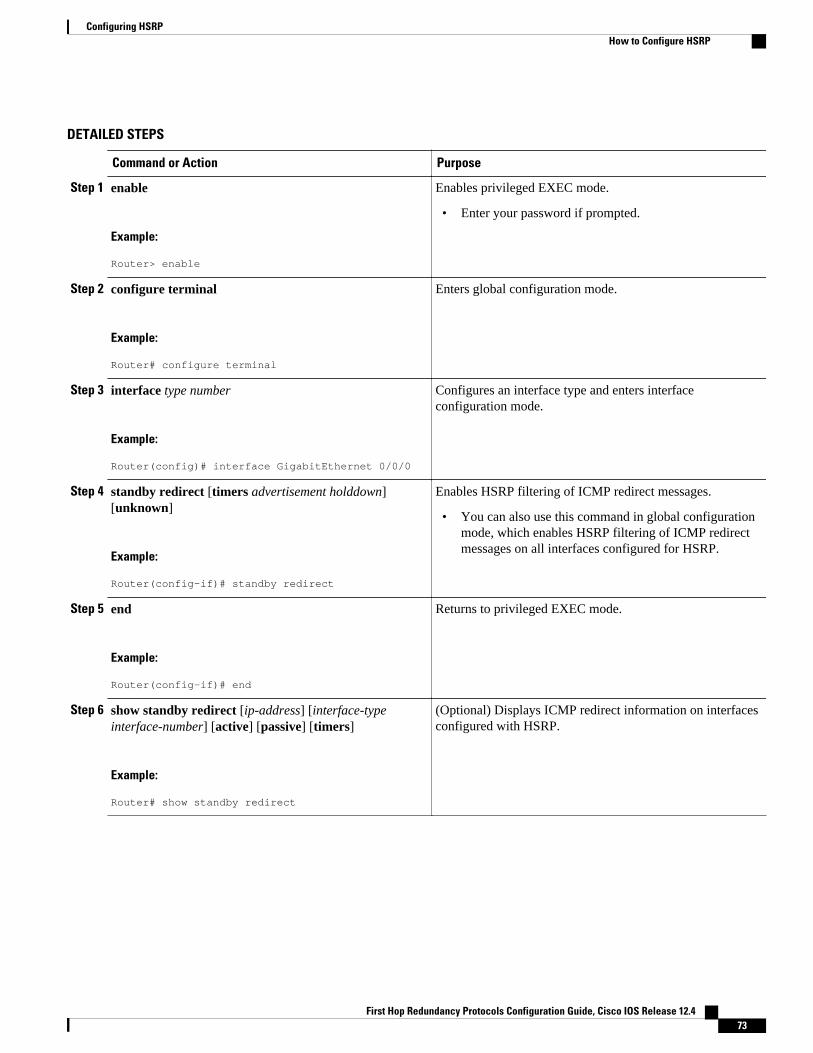
DETAILED STEPS
Command or Action Purpose
Step 1 enable
Example:
Router> enable
Enables privileged EXEC mode.
• Enter your password if prompted.
Step 2 configure terminal
Example:
Router# configure terminal
Enters global configuration mode.
Step 3 interface type number
Example:
Router(config)# interface GigabitEthernet 0/0/0
Configures an interface type and enters interfaceconfiguration mode.
Step 4 standby redirect [timers advertisement holddown][unknown]
Example:
Router(config-if)# standby redirect
Enables HSRP filtering of ICMP redirect messages.
• You can also use this command in global configurationmode, which enables HSRP filtering of ICMP redirectmessages on all interfaces configured for HSRP.
Step 5 end
Example:
Router(config-if)# end
Returns to privileged EXEC mode.
Step 6 show standby redirect [ip-address] [interface-typeinterface-number] [active] [passive] [timers]
Example:
Router# show standby redirect
(Optional) Displays ICMP redirect information on interfacesconfigured with HSRP.
Configuring HSRPHow to Configure HSRP
First Hop Redundancy Protocols Configuration Guide, Cisco IOS Release 12.4 73
Configuring HSRP Virtual MAC Addresses or BIA MAC Addresses
Note You cannot use the standby use-bia and standby mac-address commands in the same configuration; theyare mutually exclusive.
The standby use-bia command has the following disadvantages:
• When a router becomes active the virtual IP address is moved to a different MAC address. The newlyactive router sends a gratuitous ARP response, but not all host implementations handle the gratuitousARP correctly.
• Proxy ARP does not function when the standby use-bia command is configured. A standby routercannot cover for the lost proxy ARP database of the failed router.
SUMMARY STEPS
1. enable
2. configure terminal
3. interface type number
4. ip address ip-address mask [secondary]
5. Enter one of the following commands:
• standby [group-number] mac-address mac-address• or• standby use-bia [scope interface]
• or
6. standby [group-number] ip [ip-address [secondary]]
DETAILED STEPS
Command or Action Purpose
Step 1 enable
Example:
Router> enable
Enables privileged EXEC mode.
• Enter your password if prompted.
Step 2 configure terminal
Example:
Router# configure terminal
Enters global configuration mode.
Configuring HSRP Virtual MAC Addresses or BIA MAC Addresses How to Configure HSRP
First Hop Redundancy Protocols Configuration Guide, Cisco IOS Release 12.474
Command or Action Purpose
Step 3 interface type number
Example:
Router(config)# interface GigabitEthernet 0/0/0
Configures an interface type and enters interfaceconfiguration mode.
Step 4 ip address ip-address mask [secondary]
Example:
Router(config-if)# ip address 172.16.6.5 255.255.255.0
Configures an IP address for an interface.
Step 5 Enter one of the following commands:
• standby [group-number] mac-address mac-address• or• standby use-bia [scope interface]
• or
Example:
Router(config-if)# standby 1 mac-address 5000.1000.1060
Example:
Router(config-if)# standby use-bia
Specifies a virtual MAC address for HSRP.
• This command cannot be used on a Token Ringinterface.
or
Configures HSRP to use the burned-in address of theinterface as its virtual MAC address.
• The scope interface keywords specify that thecommand is configured just for the subinterface onwhich it was entered, instead of the major interface.
Step 6 standby [group-number] ip [ip-address [secondary]]
Example:
Router(config-if)# standby 1 ip 172.16.6.100
Activates HSRP.
Linking IP Redundancy Clients to HSRP GroupsWithin the client application, you must first specify the same name as configured in the standby namecommand.
Linking IP Redundancy Clients to HSRP GroupsHow to Configure HSRP
First Hop Redundancy Protocols Configuration Guide, Cisco IOS Release 12.4 75
SUMMARY STEPS
1. enable
2. configure terminal
3. interface type number
4. ip address ip-address mask
5. standby [group-number] name [redundancy-name]
6. standby [group-number] ip [ip-address [secondary]]
DETAILED STEPS
Command or Action Purpose
Step 1 enable
Example:
Router> enable
Enables privileged EXEC mode.
• Enter your password if prompted.
Step 2 configure terminal
Example:
Router# configure terminal
Enters global configuration mode.
Step 3 interface type number
Example:
Router(config)# interface Ethernet 0/1
Configures an interface type and enters interfaceconfiguration mode.
Step 4 ip address ip-address mask
Example:
Router(config-if)# ip address 10.0.0.1 255.255.255.0
Specifies an IP address for an interface.
Step 5 standby [group-number] name [redundancy-name]
Example:
Router(config-if)# standby 1 name HSRP-1
Configures the name of the standby group.
• HSRP groups have a default name of hsrp-interface-group so specifying a group name is optional.
Configuring HSRP How to Configure HSRP
First Hop Redundancy Protocols Configuration Guide, Cisco IOS Release 12.476
Command or Action Purpose
Step 6 standby [group-number] ip [ip-address [secondary]]
Example:
Router(config-if)# standby 1 ip 10.0.0.11
Activates HSRP.
Changing to HSRP Version 2HSRP version 2 was introduced to prepare for further enhancements and to expand the capabilities beyondwhat is possible with HSRP version 1. HSRP version 2 has a different packet format than HSRP version 1.
Note• HSRP version 2 is not available for ATM interfaces running LAN emulation.• HSRP version 2 will not interoperate with HSRP version 1. An interface cannot operate both version 1
and version 2 because both versions are mutually exclusive. However, the different versions can berun on different physical interfaces of the same router. You cannot change from version 2 to version 1if you have configured groups above the group number range allowed for version 1 (0 to 255).
SUMMARY STEPS
1. enable
2. configure terminal
3. interface type number
4. ip address ip-address mask
5. standby version {1 | 2}
6. standby [group-number] ip [ip-address [secondary]]
7. end
8. show standby
DETAILED STEPS
Command or Action Purpose
Step 1 enable
Example:
Router> enable
Enables privileged EXEC mode.
• Enter your password if prompted.
Changing to HSRP Version 2How to Configure HSRP
First Hop Redundancy Protocols Configuration Guide, Cisco IOS Release 12.4 77
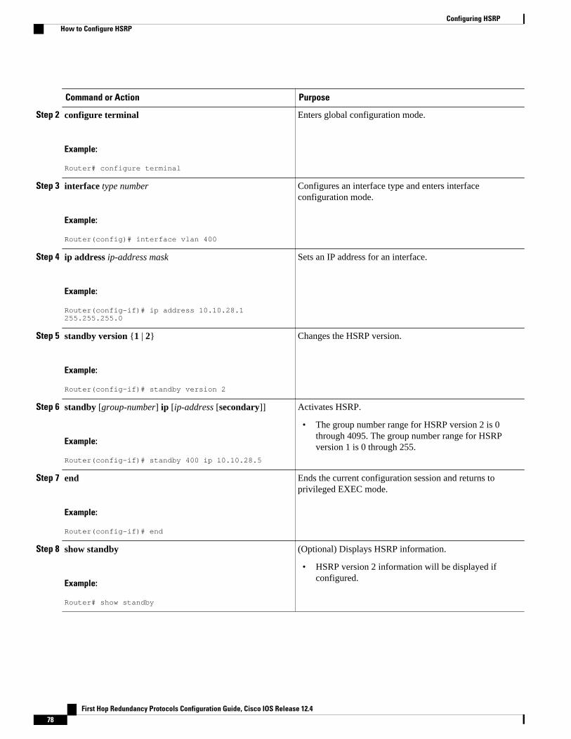
Command or Action Purpose
Step 2 configure terminal
Example:
Router# configure terminal
Enters global configuration mode.
Step 3 interface type number
Example:
Router(config)# interface vlan 400
Configures an interface type and enters interfaceconfiguration mode.
Step 4 ip address ip-address mask
Example:
Router(config-if)# ip address 10.10.28.1 255.255.255.0
Sets an IP address for an interface.
Step 5 standby version {1 | 2}
Example:
Router(config-if)# standby version 2
Changes the HSRP version.
Step 6 standby [group-number] ip [ip-address [secondary]]
Example:
Router(config-if)# standby 400 ip 10.10.28.5
Activates HSRP.
• The group number range for HSRP version 2 is 0through 4095. The group number range for HSRPversion 1 is 0 through 255.
Step 7 end
Example:
Router(config-if)# end
Ends the current configuration session and returns toprivileged EXEC mode.
Step 8 show standby
Example:
Router# show standby
(Optional) Displays HSRP information.
• HSRP version 2 information will be displayed ifconfigured.
Configuring HSRP How to Configure HSRP
First Hop Redundancy Protocols Configuration Guide, Cisco IOS Release 12.478
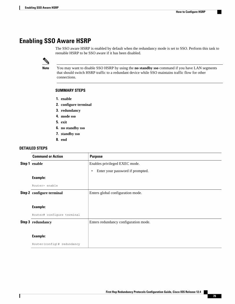
Enabling SSO Aware HSRPThe SSO aware HSRP is enabled by default when the redundancy mode is set to SSO. Perform this task toreenable HSRP to be SSO aware if it has been disabled.
Note You may want to disable SSO HSRP by using the no standby sso command if you have LAN segmentsthat should switch HSRP traffic to a redundant device while SSO maintains traffic flow for otherconnections.
SUMMARY STEPS
1. enable
2. configure terminal
3. redundancy
4. mode sso
5. exit
6. no standby sso
7. standby sso
8. end
DETAILED STEPS
Command or Action Purpose
Step 1 enable
Example:
Router> enable
Enables privileged EXEC mode.
• Enter your password if prompted.
Step 2 configure terminal
Example:
Router# configure terminal
Enters global configuration mode.
Step 3 redundancy
Example:
Router(config)# redundancy
Enters redundancy configuration mode.
Enabling SSO Aware HSRPHow to Configure HSRP
First Hop Redundancy Protocols Configuration Guide, Cisco IOS Release 12.4 79
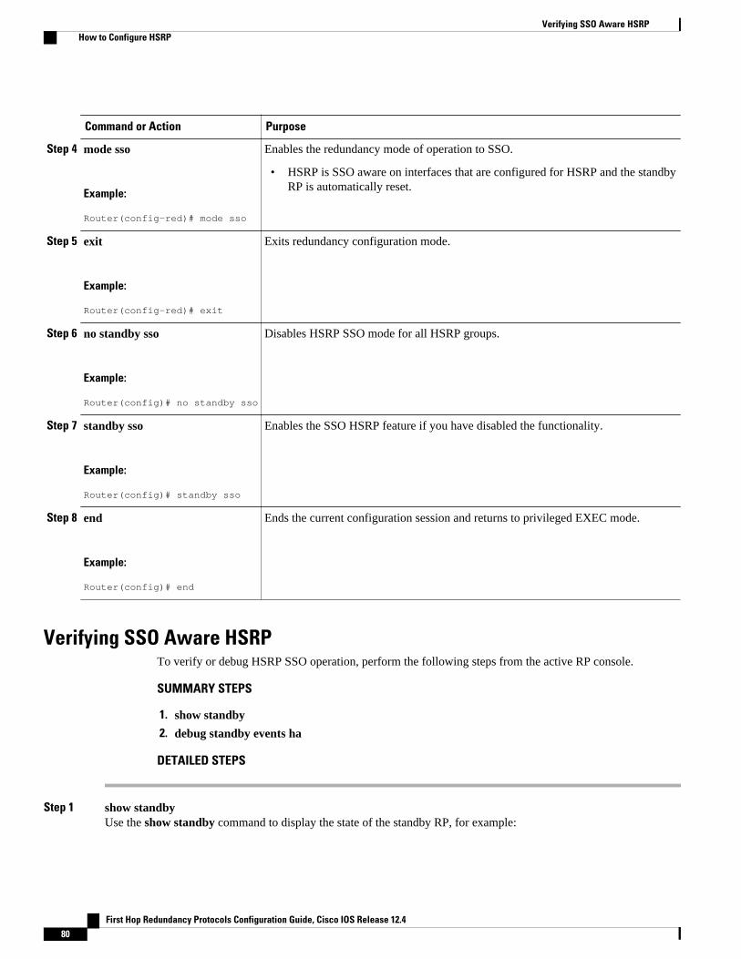
Command or Action Purpose
Step 4 mode sso
Example:
Router(config-red)# mode sso
Enables the redundancy mode of operation to SSO.
• HSRP is SSO aware on interfaces that are configured for HSRP and the standbyRP is automatically reset.
Step 5 exit
Example:
Router(config-red)# exit
Exits redundancy configuration mode.
Step 6 no standby sso
Example:
Router(config)# no standby sso
Disables HSRP SSO mode for all HSRP groups.
Step 7 standby sso
Example:
Router(config)# standby sso
Enables the SSO HSRP feature if you have disabled the functionality.
Step 8 end
Example:
Router(config)# end
Ends the current configuration session and returns to privileged EXEC mode.
Verifying SSO Aware HSRPTo verify or debug HSRP SSO operation, perform the following steps from the active RP console.
SUMMARY STEPS
1. show standby
2. debug standby events ha
DETAILED STEPS
Step 1 show standbyUse the show standby command to display the state of the standby RP, for example:
Verifying SSO Aware HSRP How to Configure HSRP
First Hop Redundancy Protocols Configuration Guide, Cisco IOS Release 12.480
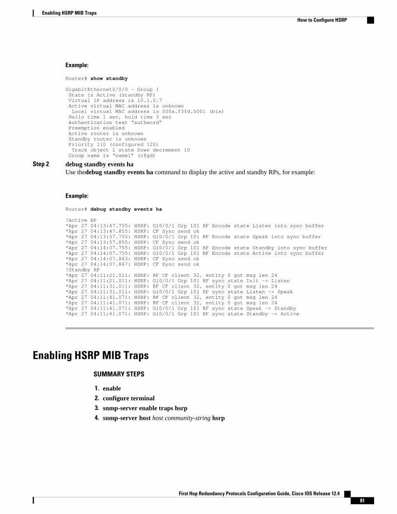
Example:
Router# show standby
GigabitEthernet0/0/0 - Group 1 State is Active (standby RP) Virtual IP address is 10.1.0.7 Active virtual MAC address is unknown Local virtual MAC address is 000a.f3fd.5001 (bia) Hello time 1 sec, hold time 3 sec Authentication text “authword” Preemption enabled Active router is unknown Standby router is unknown Priority 110 (configured 120) Track object 1 state Down decrement 10 Group name is “name1” (cfgd)
Step 2 debug standby events haUse thedebug standby events ha command to display the active and standby RPs, for example:
Example:
Router# debug standby events ha
!Active RP*Apr 27 04:13:47.755: HSRP: Gi0/0/1 Grp 101 RF Encode state Listen into sync buffer*Apr 27 04:13:47.855: HSRP: CF Sync send ok*Apr 27 04:13:57.755: HSRP: Gi0/0/1 Grp 101 RF Encode state Speak into sync buffer*Apr 27 04:13:57.855: HSRP: CF Sync send ok*Apr 27 04:14:07.755: HSRP: Gi0/0/1 Grp 101 RF Encode state Standby into sync buffer*Apr 27 04:14:07.755: HSRP: Gi0/0/1 Grp 101 RF Encode state Active into sync buffer*Apr 27 04:14:07.863: HSRP: CF Sync send ok*Apr 27 04:14:07.867: HSRP: CF Sync send ok!Standby RP*Apr 27 04:11:21.011: HSRP: RF CF client 32, entity 0 got msg len 24*Apr 27 04:11:21.011: HSRP: Gi0/0/1 Grp 101 RF sync state Init -> Listen*Apr 27 04:11:31.011: HSRP: RF CF client 32, entity 0 got msg len 24*Apr 27 04:11:31.011: HSRP: Gi0/0/1 Grp 101 RF sync state Listen -> Speak*Apr 27 04:11:41.071: HSRP: RF CF client 32, entity 0 got msg len 24*Apr 27 04:11:41.071: HSRP: RF CF client 32, entity 0 got msg len 24*Apr 27 04:11:41.071: HSRP: Gi0/0/1 Grp 101 RF sync state Speak -> Standby*Apr 27 04:11:41.071: HSRP: Gi0/0/1 Grp 101 RF sync state Standby -> Active
Enabling HSRP MIB Traps
SUMMARY STEPS
1. enable
2. configure terminal
3. snmp-server enable traps hsrp
4. snmp-server host host community-string hsrp
Enabling HSRP MIB TrapsHow to Configure HSRP
First Hop Redundancy Protocols Configuration Guide, Cisco IOS Release 12.4 81
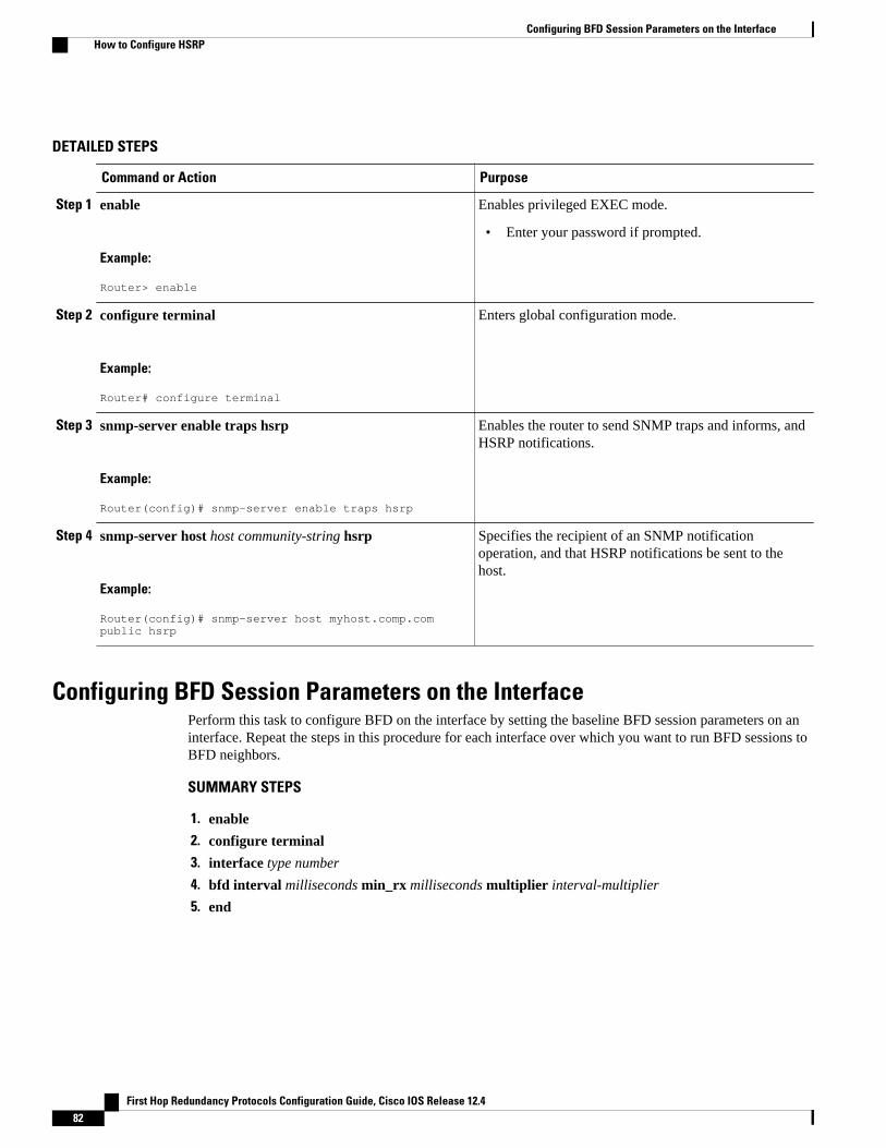
DETAILED STEPS
Command or Action Purpose
Step 1 enable
Example:
Router> enable
Enables privileged EXEC mode.
• Enter your password if prompted.
Step 2 configure terminal
Example:
Router# configure terminal
Enters global configuration mode.
Step 3 snmp-server enable traps hsrp
Example:
Router(config)# snmp-server enable traps hsrp
Enables the router to send SNMP traps and informs, andHSRP notifications.
Step 4 snmp-server host host community-string hsrp
Example:
Router(config)# snmp-server host myhost.comp.com public hsrp
Specifies the recipient of an SNMP notificationoperation, and that HSRP notifications be sent to thehost.
Configuring BFD Session Parameters on the InterfacePerform this task to configure BFD on the interface by setting the baseline BFD session parameters on aninterface. Repeat the steps in this procedure for each interface over which you want to run BFD sessions toBFD neighbors.
SUMMARY STEPS
1. enable
2. configure terminal
3. interface type number
4. bfd interval milliseconds min_rx milliseconds multiplier interval-multiplier
5. end
Configuring BFD Session Parameters on the Interface How to Configure HSRP
First Hop Redundancy Protocols Configuration Guide, Cisco IOS Release 12.482
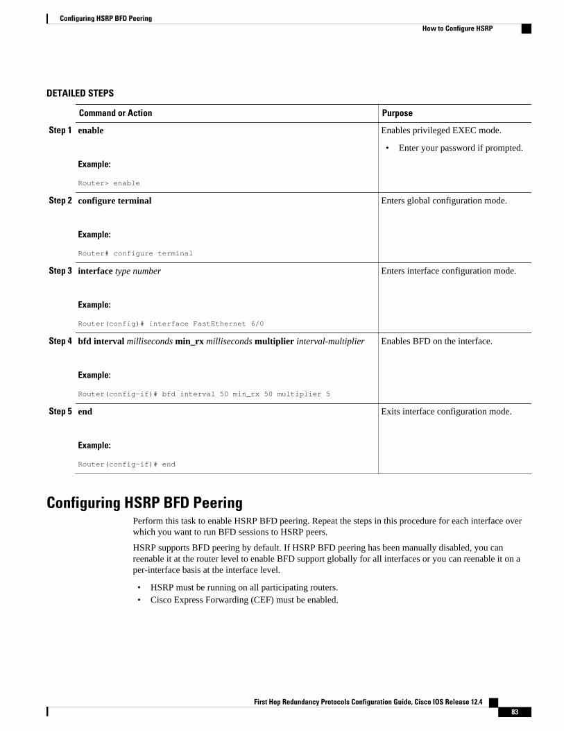
DETAILED STEPS
Command or Action Purpose
Step 1 enable
Example:
Router> enable
Enables privileged EXEC mode.
• Enter your password if prompted.
Step 2 configure terminal
Example:
Router# configure terminal
Enters global configuration mode.
Step 3 interface type number
Example:
Router(config)# interface FastEthernet 6/0
Enters interface configuration mode.
Step 4 bfd interval milliseconds min_rx milliseconds multiplier interval-multiplier
Example:
Router(config-if)# bfd interval 50 min_rx 50 multiplier 5
Enables BFD on the interface.
Step 5 end
Example:
Router(config-if)# end
Exits interface configuration mode.
Configuring HSRP BFD PeeringPerform this task to enable HSRP BFD peering. Repeat the steps in this procedure for each interface overwhich you want to run BFD sessions to HSRP peers.
HSRP supports BFD peering by default. If HSRP BFD peering has been manually disabled, you canreenable it at the router level to enable BFD support globally for all interfaces or you can reenable it on aper-interface basis at the interface level.
• HSRP must be running on all participating routers.• Cisco Express Forwarding (CEF) must be enabled.
Configuring HSRP BFD PeeringHow to Configure HSRP
First Hop Redundancy Protocols Configuration Guide, Cisco IOS Release 12.4 83
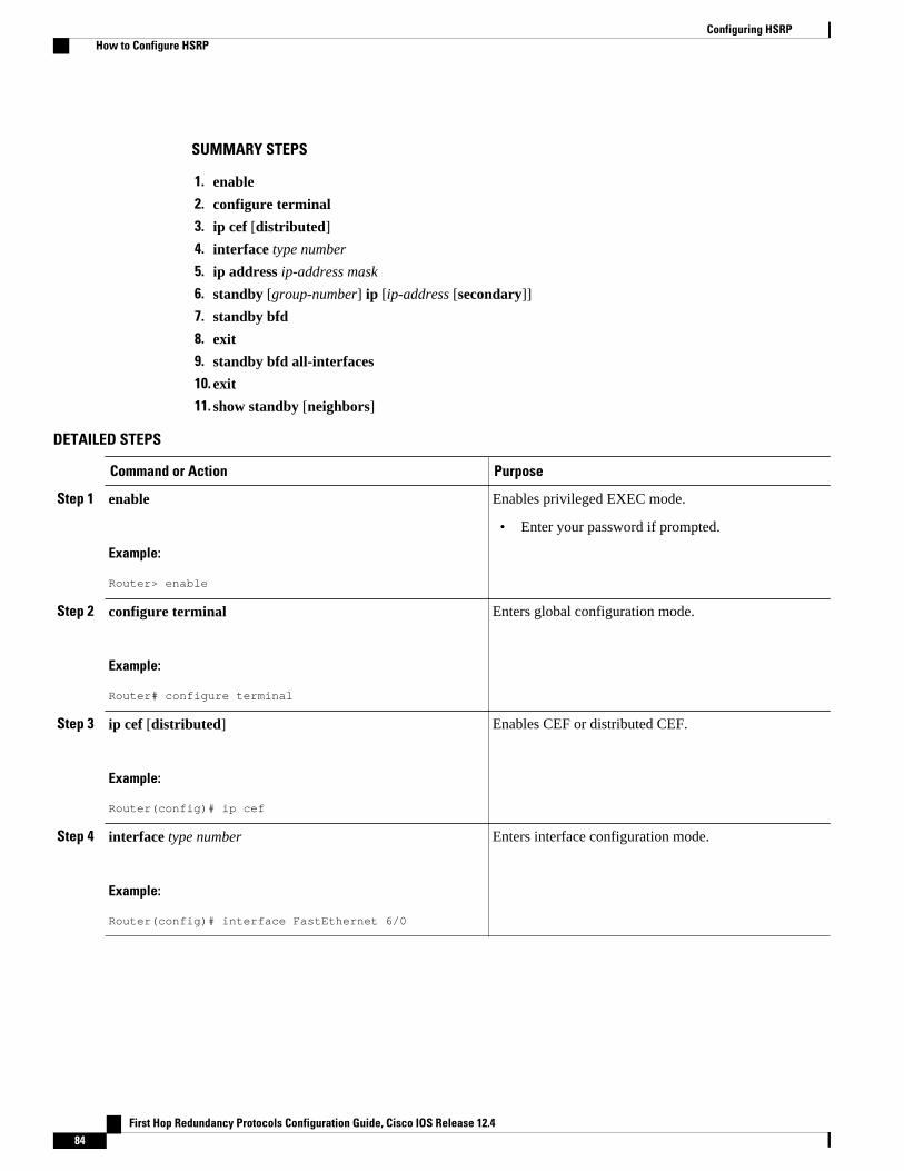
SUMMARY STEPS
1. enable
2. configure terminal
3. ip cef [distributed]
4. interface type number
5. ip address ip-address mask
6. standby [group-number] ip [ip-address [secondary]]
7. standby bfd
8. exit
9. standby bfd all-interfaces
10. exit
11. show standby [neighbors]
DETAILED STEPS
Command or Action Purpose
Step 1 enable
Example:
Router> enable
Enables privileged EXEC mode.
• Enter your password if prompted.
Step 2 configure terminal
Example:
Router# configure terminal
Enters global configuration mode.
Step 3 ip cef [distributed]
Example:
Router(config)# ip cef
Enables CEF or distributed CEF.
Step 4 interface type number
Example:
Router(config)# interface FastEthernet 6/0
Enters interface configuration mode.
Configuring HSRP How to Configure HSRP
First Hop Redundancy Protocols Configuration Guide, Cisco IOS Release 12.484
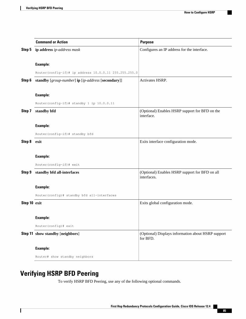
Command or Action Purpose
Step 5 ip address ip-address mask
Example:
Router(config-if)# ip address 10.0.0.11 255.255.255.0
Configures an IP address for the interface.
Step 6 standby [group-number] ip [ip-address [secondary]]
Example:
Router(config-if)# standby 1 ip 10.0.0.11
Activates HSRP.
Step 7 standby bfd
Example:
Router(config-if)# standby bfd
(Optional) Enables HSRP support for BFD on theinterface.
Step 8 exit
Example:
Router(config-if)# exit
Exits interface configuration mode.
Step 9 standby bfd all-interfaces
Example:
Router(config)# standby bfd all-interfaces
(Optional) Enables HSRP support for BFD on allinterfaces.
Step 10 exit
Example:
Router(config)# exit
Exits global configuration mode.
Step 11 show standby [neighbors]
Example:
Router# show standby neighbors
(Optional) Displays information about HSRP supportfor BFD.
Verifying HSRP BFD PeeringTo verify HSRP BFD Peering, use any of the following optional commands.
Verifying HSRP BFD PeeringHow to Configure HSRP
First Hop Redundancy Protocols Configuration Guide, Cisco IOS Release 12.4 85
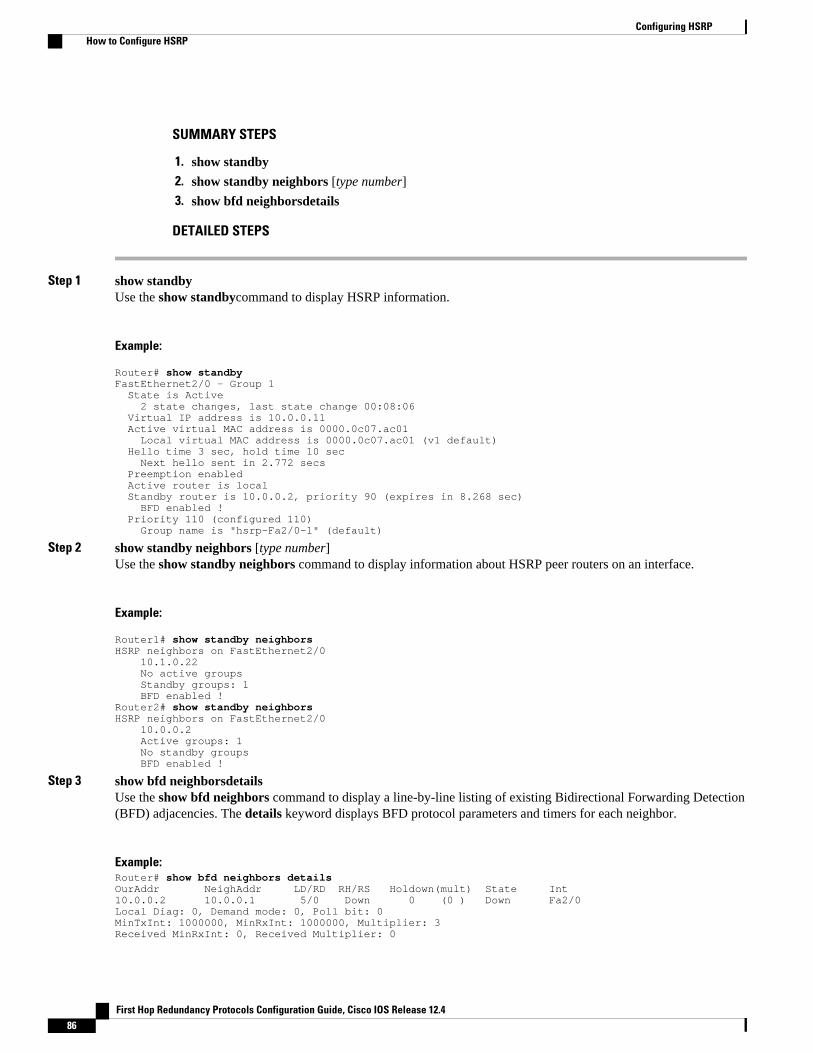
SUMMARY STEPS
1. show standby
2. show standby neighbors [type number]
3. show bfd neighborsdetails
DETAILED STEPS
Step 1 show standbyUse the show standbycommand to display HSRP information.
Example:
Router# show standbyFastEthernet2/0 - Group 1 State is Active 2 state changes, last state change 00:08:06 Virtual IP address is 10.0.0.11 Active virtual MAC address is 0000.0c07.ac01 Local virtual MAC address is 0000.0c07.ac01 (v1 default) Hello time 3 sec, hold time 10 sec Next hello sent in 2.772 secs Preemption enabled Active router is local Standby router is 10.0.0.2, priority 90 (expires in 8.268 sec) BFD enabled ! Priority 110 (configured 110) Group name is "hsrp-Fa2/0-1" (default)
Step 2 show standby neighbors [type number]Use the show standby neighbors command to display information about HSRP peer routers on an interface.
Example:
Router1# show standby neighborsHSRP neighbors on FastEthernet2/0 10.1.0.22 No active groups Standby groups: 1 BFD enabled !Router2# show standby neighborsHSRP neighbors on FastEthernet2/0 10.0.0.2 Active groups: 1 No standby groups BFD enabled !
Step 3 show bfd neighborsdetailsUse the show bfd neighbors command to display a line-by-line listing of existing Bidirectional Forwarding Detection(BFD) adjacencies. The details keyword displays BFD protocol parameters and timers for each neighbor.
Example:Router# show bfd neighbors detailsOurAddr NeighAddr LD/RD RH/RS Holdown(mult) State Int10.0.0.2 10.0.0.1 5/0 Down 0 (0 ) Down Fa2/0Local Diag: 0, Demand mode: 0, Poll bit: 0MinTxInt: 1000000, MinRxInt: 1000000, Multiplier: 3Received MinRxInt: 0, Received Multiplier: 0
Configuring HSRP How to Configure HSRP
First Hop Redundancy Protocols Configuration Guide, Cisco IOS Release 12.486
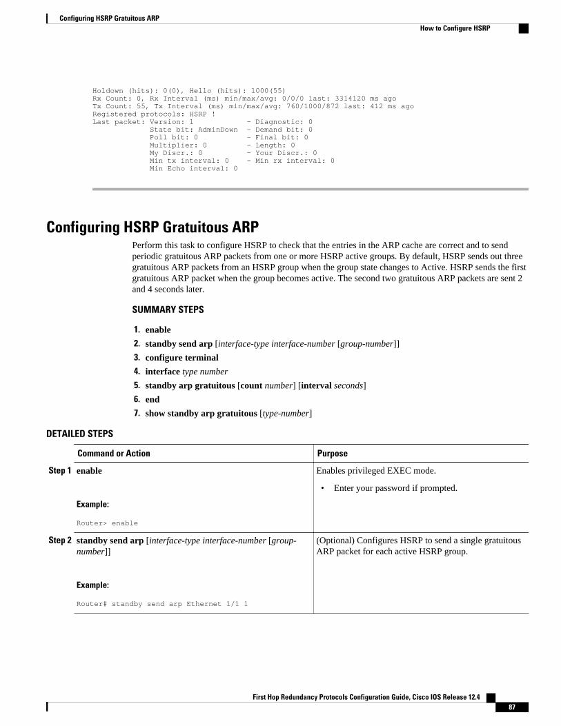
Holdown (hits): 0(0), Hello (hits): 1000(55)Rx Count: 0, Rx Interval (ms) min/max/avg: 0/0/0 last: 3314120 ms agoTx Count: 55, Tx Interval (ms) min/max/avg: 760/1000/872 last: 412 ms agoRegistered protocols: HSRP !Last packet: Version: 1 - Diagnostic: 0 State bit: AdminDown - Demand bit: 0 Poll bit: 0 - Final bit: 0 Multiplier: 0 - Length: 0 My Discr.: 0 - Your Discr.: 0 Min tx interval: 0 - Min rx interval: 0 Min Echo interval: 0
Configuring HSRP Gratuitous ARPPerform this task to configure HSRP to check that the entries in the ARP cache are correct and to sendperiodic gratuitous ARP packets from one or more HSRP active groups. By default, HSRP sends out threegratuitous ARP packets from an HSRP group when the group state changes to Active. HSRP sends the firstgratuitous ARP packet when the group becomes active. The second two gratuitous ARP packets are sent 2and 4 seconds later.
SUMMARY STEPS
1. enable
2. standby send arp [interface-type interface-number [group-number]]
3. configure terminal
4. interface type number
5. standby arp gratuitous [count number] [interval seconds]
6. end
7. show standby arp gratuitous [type-number]
DETAILED STEPS
Command or Action Purpose
Step 1 enable
Example:
Router> enable
Enables privileged EXEC mode.
• Enter your password if prompted.
Step 2 standby send arp [interface-type interface-number [group-number]]
Example:
Router# standby send arp Ethernet 1/1 1
(Optional) Configures HSRP to send a single gratuitousARP packet for each active HSRP group.
Configuring HSRP Gratuitous ARPHow to Configure HSRP
First Hop Redundancy Protocols Configuration Guide, Cisco IOS Release 12.4 87
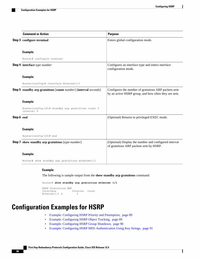
Command or Action Purpose
Step 3 configure terminal
Example:
Router# configure terminal
Enters global configuration mode.
Step 4 interface type number
Example:
Router(config)# interface Ethernet1/1
Configures an interface type and enters interfaceconfiguration mode.
Step 5 standby arp gratuitous [count number] [interval seconds]
Example:
Router(config-if)# standby arp gratuitous count 3 interval 4
Configures the number of gratuitous ARP packets sentby an active HSRP group, and how often they are sent.
Step 6 end
Example:
Router(config-if)# end
(Optional) Returns to privileged EXEC mode.
Step 7 show standby arp gratuitous [type-number]
Example:
Router# show standby arp gratuitous ethernet1/1
(Optional) Display the number and configured intervalof gratuitous ARP packets sent by HSRP.
Example
The following is sample output from the show standby arp gratuitous command:
Router# show standby arp gratuitous ethernet 1/1
HSRP Gratuitous ARPInterface Interval Count Ethernet1/1 4 3
Configuration Examples for HSRP• Example: Configuring HSRP Priority and Preemption, page 89• Example: Configuring HSRP Object Tracking, page 89• Example: Configuring HSRP Group Shutdown, page 90• Example: Configuring HSRP MD5 Authentication Using Key Strings, page 91
Configuring HSRP Configuration Examples for HSRP
First Hop Redundancy Protocols Configuration Guide, Cisco IOS Release 12.488
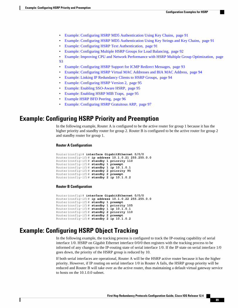
• Example: Configuring HSRP MD5 Authentication Using Key Chains, page 91• Example: Configuring HSRP MD5 Authentication Using Key Strings and Key Chains, page 91• Example: Configuring HSRP Text Authentication, page 91• Example: Configuring Multiple HSRP Groups for Load Balancing, page 92• Example: Improving CPU and Network Performance with HSRP Multiple Group Optimization, page93• Example: Configuring HSRP Support for ICMP Redirect Messages, page 93• Example: Configuring HSRP Virtual MAC Addresses and BIA MAC Address, page 94• Example: Linking IP Redundancy Clients to HSRP Groups, page 94• Example: Configuring HSRP Version 2, page 95• Example: Enabling SSO-Aware HSRP, page 95• Example: Enabling HSRP MIB Traps, page 95• Example HSRP BFD Peering, page 96• Example: Configuring HSRP Gratuitous ARP, page 97
Example: Configuring HSRP Priority and PreemptionIn the following example, Router A is configured to be the active router for group 1 because it has thehigher priority and standby router for group 2. Router B is configured to be the active router for group 2and standby router for group 1.
Router A Configuration
Router(config)# interface GigabitEthernet 0/0/0Router(config-if)# ip address 10.1.0.21 255.255.0.0Router(config-if)# standby 1 priority 110Router(config-if)# standby 1 preemptRouter(config-if)# standby 1 ip 10.1.0.1Router(config-if)# standby 2 priority 95Router(config-if)# standby 2 preemptRouter(config-if)# standby 2 ip 10.1.0.2
Router B Configuration
Router(config)# interface GigabitEthernet 0/0/0Router(config-if)# ip address 10.1.0.22 255.255.0.0Router(config-if)# standby 1 preemptRouter(config-if)# standby 1 priority 105Router(config-if)# standby 1 ip 10.1.0.1Router(config-if)# standby 2 priority 110Router(config-if)# standby 2 preemptRouter(config-if)# standby 2 ip 10.1.0.2
Example: Configuring HSRP Object TrackingIn the following example, the tracking process is configured to track the IP-routing capability of serialinterface 1/0. HSRP on Gigabit Ethernet interface 0/0/0 then registers with the tracking process to beinformed of any changes to the IP-routing state of serial interface 1/0. If the IP state on serial interface 1/0goes down, the priority of the HSRP group is reduced by 10.
If both serial interfaces are operational, Router A will be the HSRP active router because it has the higherpriority. However, if IP routing on serial interface 1/0 in Router A fails, the HSRP group priority will bereduced and Router B will take over as the active router, thus maintaining a default virtual gateway serviceto hosts on the 10.1.0.0 subnet.
Example: Configuring HSRP Priority and PreemptionConfiguration Examples for HSRP
First Hop Redundancy Protocols Configuration Guide, Cisco IOS Release 12.4 89
Router A Configuration
Router(config)# track 100 interface serial 1/0/0 ip routing!Router(config)# interface GigabitEthernet 0/0/0Router(config-if)# ip address 10.1.0.21 255.255.0.0Router(config-if)# standby 1 preemptRouter(config-if)# standby 1 priority 110Router(config-if)# standby 1 track 100 decrement 10Router(config-if)# standby 1 ip 10.1.0.1
Router B Configuration
Router(config)# track 100 interface serial 1/0/0 ip routing!Router(config)# interface GigabitEthernet 0/0/0Router(config-if)# ip address 10.1.0.22 255.255.0.0Router(config-if)# standby 1 preemptRouter(config-if)# standby 1 priority 105Router(config-if)# standby 1 track 100 decrement 10Router(config-if)# standby 1 ip 10.1.0.1
Example: Configuring HSRP Group ShutdownIn the following example, the tracking process is configured to track the IP-routing capability of GigabitEthernet interface 0/0/0. HSRP on Gigabit Ethernet interface 0/0/1 then registers with the tracking processto be informed of any changes to the IP-routing state of Gigabit Ethernet interface 0/0/0. If the IP state onGigabit Ethernet interface 0/0/0 goes down, the HSRP group is disabled.
If both Gigabit Ethernet interfaces are operational, Router A will be the HSRP active router because it hasthe higher priority. However, if IP routing on Gigabit Ethernet interface 0/0/0 in Router A fails, the HSRPgroup will be disabled and Router B will take over as the active router, thus maintaining a default virtualgateway service to hosts on the 10.1.0.0 subnet.
Router A Configuration
Router(config)# track 100 interface GigabitEthernet 0/0/0 ip routing !Router(config)# interface GigabitEthernet 0/0/1Router(config-if)# ip address 10.1.0.21 255.255.0.0Router(config-if)# standby 1 ip 10.1.0.1Router(config-if)# standby 1 preemptRouter(config-if)# standby 1 priority 110Router(config-if)# standby 1 track 100 shutdown
Router B Configuration
Router(config)# track 100 interface GigabitEthernet 0/0/0 ip routing !Router(config)# interface GigabitEthernet 0/0/1Router(config-if)# ip address 10.1.0.22 255.255.0.0Router(config-if)# standby 1 ip 10.1.0.1Router(config-if)# standby 1 preemptRouter(config-if)# standby 1 priority 105Router(config-if)# standby 1 track 100 shutdown
If an object is already being tracked by an HSRP group, you cannot change the configuration to use theHSRP Group Shutdown feature. You must first remove the tracking configuration using the no standbytrack command and then reconfigure it using the standby track command with the shutdown keyword.
Example: Configuring HSRP Group Shutdown Configuration Examples for HSRP
First Hop Redundancy Protocols Configuration Guide, Cisco IOS Release 12.490
The following example shows how to change the configuration of a tracked object to include the HSRPGroup Shutdown feature:
Router(config)# no standby 1 track 100 decrement 10Router(config)# standby 1 track 100 shutdown
Example: Configuring HSRP MD5 Authentication Using Key StringsRouter(config)# interface GigabitEthernet 0/0/0Router(config-if)# standby 1 priority 110Router(config-if)# standby 1 preemptRouter(config-if)# standby 1 authentication md5 key-string 54321098452103ab timeout 30Router(config-if)# standby 1 ip 10.21.0.10
Example: Configuring HSRP MD5 Authentication Using Key ChainsIn the following example, HSRP queries the key chain “hsrp1” to obtain the current live key and key ID forthe specified key chain:
Router(config)# key chain hsrp1Router(config-keychain)# key 1Router(config-keychain-key)# key-string 54321098452103abRouter(config-keychain-key)# exitRouter(config)# interface GigabitEthernet 0/0/0Router(config-if)# standby 1 priority 110Router(config-if)# standby 1 preemptRouter(config-if)# standby 1 authentication md5 key-chain hsrp1Router(config-if)# standby 1 ip 10.21.0.10
Example: Configuring HSRP MD5 Authentication Using Key Strings and KeyChains
The key ID for key-string authentication is always zero. If a key chain is configured with a key ID of zero,then the following configuration will work:
Router 1
Router(config)# key chain hsrp1Router(config-keychain)# key 0Router(config-keychain-key)# key-string 54321098452103abRouter(config-keychain-key)# exitRouter(config)# interface GigabitEthernet 0/0/0Router(config-if)# standby 1 authentication md5 key-chain hsrp1Router(config-if)# standby 1 ip 10.21.0.10
Router 2
Router(config)# interface GigabitEthernet 0/0/0Router(config-if)# standby 1 authentication md5 key-string 54321098452103abRouter(config-if)# standby 1 ip 10.21.0.10
Example: Configuring HSRP Text AuthenticationRouter(config)# interface GigabitEthernet 0/0/0Router(config-if)# standby 1 priority 110Router(config-if)# standby 1 preempt
Example: Configuring HSRP MD5 Authentication Using Key StringsConfiguration Examples for HSRP
First Hop Redundancy Protocols Configuration Guide, Cisco IOS Release 12.4 91
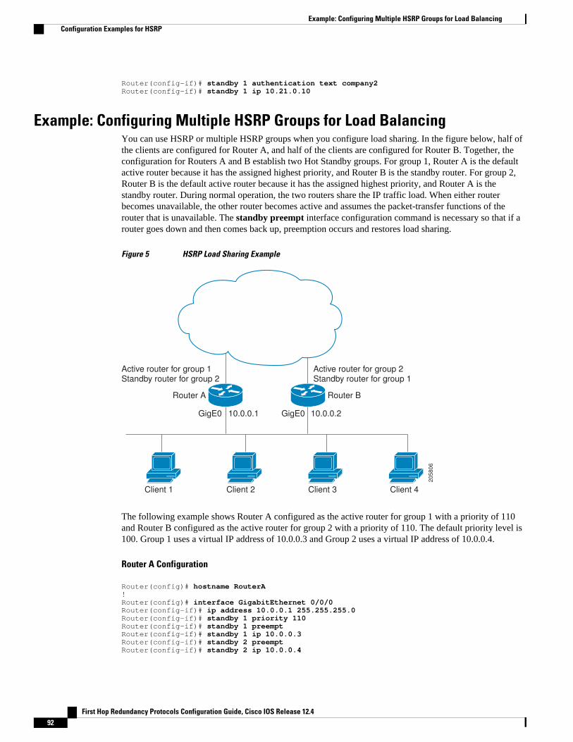
Router(config-if)# standby 1 authentication text company2Router(config-if)# standby 1 ip 10.21.0.10
Example: Configuring Multiple HSRP Groups for Load BalancingYou can use HSRP or multiple HSRP groups when you configure load sharing. In the figure below, half ofthe clients are configured for Router A, and half of the clients are configured for Router B. Together, theconfiguration for Routers A and B establish two Hot Standby groups. For group 1, Router A is the defaultactive router because it has the assigned highest priority, and Router B is the standby router. For group 2,Router B is the default active router because it has the assigned highest priority, and Router A is thestandby router. During normal operation, the two routers share the IP traffic load. When either routerbecomes unavailable, the other router becomes active and assumes the packet-transfer functions of therouter that is unavailable. The standby preempt interface configuration command is necessary so that if arouter goes down and then comes back up, preemption occurs and restores load sharing.
Figure 5 HSRP Load Sharing Example
205806
Active router for group 1Standby router for group 2
Client 1
GigE0
Router A Router B
10.0.0.1 GigE0 10.0.0.2
Active router for group 2Standby router for group 1
Client 2 Client 3 Client 4
The following example shows Router A configured as the active router for group 1 with a priority of 110and Router B configured as the active router for group 2 with a priority of 110. The default priority level is100. Group 1 uses a virtual IP address of 10.0.0.3 and Group 2 uses a virtual IP address of 10.0.0.4.
Router A Configuration
Router(config)# hostname RouterA!Router(config)# interface GigabitEthernet 0/0/0Router(config-if)# ip address 10.0.0.1 255.255.255.0Router(config-if)# standby 1 priority 110Router(config-if)# standby 1 preemptRouter(config-if)# standby 1 ip 10.0.0.3Router(config-if)# standby 2 preemptRouter(config-if)# standby 2 ip 10.0.0.4
Example: Configuring Multiple HSRP Groups for Load Balancing Configuration Examples for HSRP
First Hop Redundancy Protocols Configuration Guide, Cisco IOS Release 12.492
Router B Configuration
Router(config)# hostname RouterB!Router(config)# interface GigabitEthernet 0/0/0Router(config-if)# ip address 10.0.0.2 255.255.255.0Router(config-if)# standby 1 preemptRouter(config-if)# standby 1 ip 10.0.0.3Router(config-if)# standby 2 priority 110Router(config-if)# standby 2 preemptRouter(config-if)# standby 2 ip 10.0.0.4
Example: Improving CPU and Network Performance with HSRP MultipleGroup Optimization
The following example shows how to configure an HSRP client and master group:
Router(config)# interface GigabitEthernet 0/0/0Router(config-if)# no shutdownRouter(config-if)# standby mac-refresh 30 ! Client Hello message interval!Router(config)# interface GigabitEthernet 0/0/1Router(config-if)# no shutdownRouter(config-if)# ip vrf forwarding VRF2Router(config-if)# ip address 10.0.0.100 255.255.0.0Router(config-if)# standby 1 ip 10.0.0.254Router(config-if)# standby 1 priority 110Router(config-if)# standby 1 preemptRouter(config-if)# standby 1 name HSRP1 !Server group!Router(config)# interface GigabitEthernet 0/0/2Router(config-if)# no shutdownRouter(config-if)# ip vrf forwarding VRF3Router(config-if)# ip address 10.0.0.100 255.255.0.0Router(config-if)# standby 2 ip 10.0.0.254Router(config-if)# standby 2 follow HSRP1 ! Client group!Router(config)# interface GigabitEthernet 0/0/3Router(config-if)# no shutdownRouter(config-if)# ip vrf forwarding VRF4Router(config-if)# ip address 10.0.0.100 255.255.0.0Router(config-if)# standby 2 ip 10.0.0.254Router(config-if)# standby 2 follow HSRP1 ! Client group
Example: Configuring HSRP Support for ICMP Redirect Messages
Router A Configuration—Active for Group 1 and Standby for Group 2
Router(config)# interface GigabitEthernet 0/0/0Router(config-if)# ip address 10.0.0.10 255.0.0.0Router(config-if)# standby redirectRouter(config-if)# standby 1 priority 120 Router(config-if)# standby 1 preempt delay minimum 20Router(config-if)# standby 1 ip 10.0.0.1Router(config-if)# standby 2 priority 105 Router(config-if)# standby 2 preempt delay minimum 20Router(config-if)# standby 2 ip 10.0.0.2
Example: Improving CPU and Network Performance with HSRP Multiple Group OptimizationConfiguration Examples for HSRP
First Hop Redundancy Protocols Configuration Guide, Cisco IOS Release 12.4 93
Router B Configuration—Standby for Group 1 and Active for Group 2
Router(config)# interface GigabitEthernet 0/0/0Router(config-if)# ip address 10.0.0.11 255.0.0.0Router(config-if)# standby redirectRouter(config-if)# standby 1 priority 105 Router(config-if)# standby 1 preempt delay minimum 20Router(config-if)# standby 1 ip 10.0.0.1Router(config-if)# standby 2 priority 120 Router(config-if)# standby 2 preempt delay minimum 20Router(config-if)# standby 2 ip 10.0.0.2
Example: Configuring HSRP Virtual MAC Addresses and BIA MAC AddressIn an Advanced Peer-to-Peer Networking (APPN) network, an end node is typically configured with theMAC address of the adjacent network node. In the following example, if the end nodes are configured touse 4000.1000.1060, HSRP group 1 is configured to use the same MAC address:
Router(config)# interface GigabitEthernet 0/0/0Router(config-if)# ip address 10.0.0.1Router(config-if)# standby 1 mac-address 4000.1000.1060Router(config-if)# standby 1 ip 10.0.0.11
In the following example, the burned-in address of Token Ring interface 3/0 will be the virtual MACaddress mapped to the virtual IP address:
Router(config)# interface token 3/0Router(config-if)# standby use-bia
Note You cannot use the standby use-bia command and the standby mac-address command in the sameconfiguration.
Example: Linking IP Redundancy Clients to HSRP GroupsThe following example shows HSRP support for a static Network Address Translation (NAT)configuration. The NAT client application is linked to HSRP via the correlation between the namespecified by the standby name command. Two routers are acting as HSRP active and standby, and theNAT inside interfaces are HSRP enabled and configured to belong to the group named “group1.”
Active Router Configuration
Router(config)# interface BVI 10 Router(config-if)# ip address 192.168.5.54 255.255.255.255.0 Router(config-if)# no ip redirects Router(config-if)# ip nat inside Router(config-if)# standby 10 ip 192.168.5.30 Router(config-if)# standby 10 priority 110 Router(config-if)# standby 10 preempt Router(config-if)# standby 10 name group1 Router(config-if)# standby 10 track Ethernet 2/1 ! ! Router(config)# ip default-gateway 10.0.18.126 Router(config)# ip nat inside source static 192.168.5.33 10.10.10.5 redundancy group1 Router(config)# ip classless Router(config)# ip route 10.10.10.0 255.255.255.0 Ethernet 2/1 Router(config)# ip route 172.22.33.0 255.255.255.0 Ethernet 2/1 Router(config)# no ip http server
Example: Configuring HSRP Virtual MAC Addresses and BIA MAC Address Configuration Examples for HSRP
First Hop Redundancy Protocols Configuration Guide, Cisco IOS Release 12.494
Standby Router Configuration
Router(config)# interface BVI 10 Router(config-if)# ip address 192.168.5.56 255.255.255.255.0 Router(config-if)# no ip redirects Router(config-if)# ip nat inside Router(config-if)# standby 10 priority 95 Router(config-if)# standby 10 preempt Router(config-if)# standby 10 name group1 Router(config-if)# standby 10 ip 192.168.5.30 Router(config-if)# standby 10 track Ethernet 3/1 Router(config-if)# exit Router(config)# ip default-gateway 10.0.18.126 Router(config)# ip nat inside source static 192.168.5.33 3.3.3.5 redundancy group1Router(config)# ip classless Router(config)# ip route 10.0.32.231 255.255.255 Ethernet 3/1 Router(config)# ip route 10.10.10.0 255.255.255.0 Ethernet 3/1 Router(config)# no ip http server
Example: Configuring HSRP Version 2The following example shows how to configure HSRP version 2 on an interface with a group number of350:
Router(config)# interface vlan 350Router(config-if)# standby version 2Router(config-if)# standby 350 priority 110 Router(config-if)# standby 350 preempt Router(config-if)# standby 350 timers 5 15Router(config-if)# standby 350 ip 172.20.100.10
Example: Enabling SSO-Aware HSRPThe following example shows how to set the redundancy mode to SSO. HSRP is automatically SSO-awarewhen this mode is enabled.
Router(config)# redundancyRouter(config-red)# mode sso
If SSO HSRP is disabled using the no standby sso command, you can reenable it as shown in thefollowing example:
Router(config)# interface GigabitEthernet 1/0/0Router(config-if)# ip address 10.1.1.1 255.255.0.0Router(config-if)# standby priority 200 Router(config-if)# standby preemptRouter(config-if)# standby sso
Example: Enabling HSRP MIB TrapsThe following examples show how to configure HSRP on two routers and enable the HSRP MIB trapsupport functionality. As in many environments, one router is preferred as the active one. To configure arouter’s preference as the active router, configure the router at a higher priority level and enablepreemption. In the following example, the active router is referred to as the primary router. The secondrouter is referred to as the backup router:
Router A
Router(config)# interface GigabitEthernet 0/0/0Router(config-if)# ip address 10.1.1.1 255.255.0.0
Example: Configuring HSRP Version 2Configuration Examples for HSRP
First Hop Redundancy Protocols Configuration Guide, Cisco IOS Release 12.4 95
Router(config-if)# standby priority 200 Router(config-if)# standby preemptRouter(config-if)# standby ip 10.1.1.3Router(config-if)# exitRouter(config)# snmp-server enable traps hsrpRouter(config)# snmp-server host yourhost.cisco.com public hsrp
Router B
Router(config)#interface GigabitEthernet 1/0/0Router(config-if)# ip address 10.1.1.2 255.255.0.0Router(config-if)# standby priority 101Router(config-if)# standby ip 10.1.1.3Router(config-if)# exitRouter(config)# snmp-server enable traps hsrpRouter(config)# snmp-server host myhost.cisco.com public hsrp
Example HSRP BFD PeeringHSRP supports BFD as a part of the HSRP group member health monitoring system. Without BFD, HSRPruns as a process in a multiprocess system and cannot be guaranteed to be scheduled in time to service largenumbers of groups with millisecond hello and hold timers. BFD runs as a pseudo-preemptive process andcan therefore be guaranteed to run when required. Only one BFD session between two routers can provideearly failover notification for multiple HSRP groups.
In the following example, the standby bfd and the standby bfd all-interfaces commands are notdisplayed. HSRP support for BFD is enabled by default when BFD is configured on the router or interfaceusing the bfd interval command. The standby bfdand standby bfd all-interfaces commands are neededonly if BFD has been manually disabled on a router or interface.
Router A
RouterA(config)# ip cefRouterA(config)# interface FastEthernet2/0RouterA(config-if)# no shutdownRouterA(config-if)# ip address 10.0.0.2 255.0.0.0RouterA(config-if)# ip router-cache cefRouterA(config-if)# bfd interval 200 min_rx 200 multiplier 3RouterA(config-if)# standby 1 ip 10.0.0.11RouterA(config-if)# standby 1 preemptRouterA(config-if)# standby 1 priority 110RouterA(config-if)# standby 2 ip 10.0.0.12RouterA(config-if)# standby 2 preemptRouterA(config-if)# standby 2 priority 110
Router B
RouterB(config)# interface FastEthernet2/0RouterB(config-if)# ip address 10.1.0.22 255.255.0.0RouterB(config-if)# no shutdownRouterB(config-if)# bfd interval 200 min_rx 200 multiplier 3RouterB(config-if)# standby 1 ip 10.0.0.11RouterB(config-if)# standby 1 preemptRouterB(config-if)# standby 1 priority 90RouterB(config-if)# standby 2 ip 10.0.0.12RouterB(config-if)# standby 2 preemptRouterB(config-if)# standby 2 priority 80
Example HSRP BFD Peering Configuration Examples for HSRP
First Hop Redundancy Protocols Configuration Guide, Cisco IOS Release 12.496
Example: Configuring HSRP Gratuitous ARPThe following example shows how to configure HSRP to check that the entries in the ARP cache arecorrect and to send three gratuitous ARP packets at 4-second intervals when an HSRP group on theinterface changes to active state:
Router> enableRouter# standby send arp Ethernet 1/1 1Router# configure terminalRouter(config)# interface Ethernet 1/1Router(config-if)# standby arp gratuitous count 3 interval 4Router(config-if)# endRouter# show standby arp gratuitous ethernet 1/1HSRP Gratuitous ARP Interface Interval Count Ethernet1/1 4 3
Additional ReferencesRelated Documents
Related Topic Document Title
Cisco IOS commands Cisco IOS Master Commands List, All Releases
BFD "Bidirectional Forwarding Detection" module in theCisco IOS IP Routing:BFD Configuration Guide
GLBP "Configuring GLBP" module
HSRP commands: complete command syntax,command mode, command history, defaults, usageguidelines, and examples
Cisco IOS IP Application Services CommandReference
HSRP and IPSec "Hot Standby Routing Protocol and IPSec" sectionin the "IPSec VPN High AvailabilityEnhancements" module in the Cisco IOS Security:Secure Connectivity Configuration Guide
HSRP and IPv6 "Configuring First Hop Redundancy ProtocolsIPv6" module in the Cisco IOS IPv6 ConfigurationGuide
ISSU • "Cisco IOS In Service Software UpgradeProcess" module of the Cisco IOS HighAvailability Configuration Guide
• Configuring the Cisco IOS In Service SoftwareUpgrade Process module of the Catalyst 4500Series Switch Cisco IOS SoftwareConfiguration Guide, Release 12.2(31)SGA.
Object tracking "Configuring Enhanced Object Tracking" module
Example: Configuring HSRP Gratuitous ARPAdditional References
First Hop Redundancy Protocols Configuration Guide, Cisco IOS Release 12.4 97
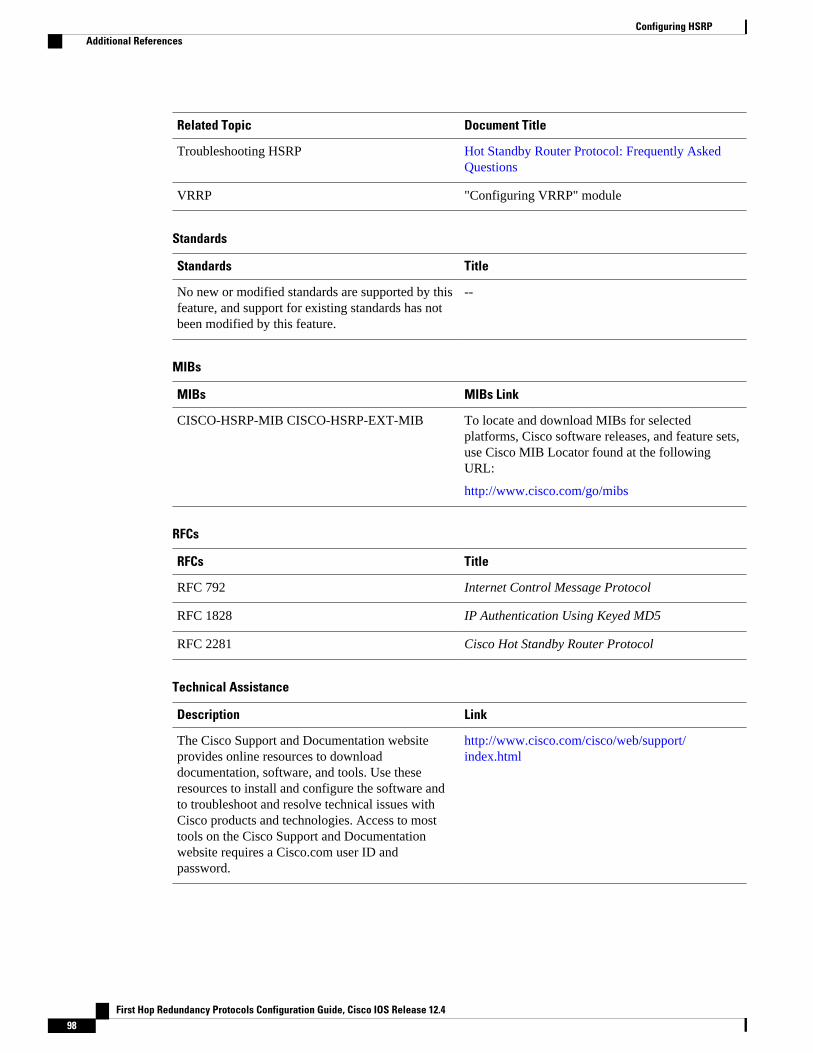
Related Topic Document Title
Troubleshooting HSRP Hot Standby Router Protocol: Frequently AskedQuestions
VRRP "Configuring VRRP" module
Standards
Standards Title
No new or modified standards are supported by thisfeature, and support for existing standards has notbeen modified by this feature.
--
MIBs
MIBs MIBs Link
CISCO-HSRP-MIB CISCO-HSRP-EXT-MIB To locate and download MIBs for selectedplatforms, Cisco software releases, and feature sets,use Cisco MIB Locator found at the followingURL:
http://www.cisco.com/go/mibs
RFCs
RFCs Title
RFC 792 Internet Control Message Protocol
RFC 1828 IP Authentication Using Keyed MD5
RFC 2281 Cisco Hot Standby Router Protocol
Technical Assistance
Description Link
The Cisco Support and Documentation websiteprovides online resources to downloaddocumentation, software, and tools. Use theseresources to install and configure the software andto troubleshoot and resolve technical issues withCisco products and technologies. Access to mosttools on the Cisco Support and Documentationwebsite requires a Cisco.com user ID andpassword.
http://www.cisco.com/cisco/web/support/index.html
Configuring HSRP Additional References
First Hop Redundancy Protocols Configuration Guide, Cisco IOS Release 12.498
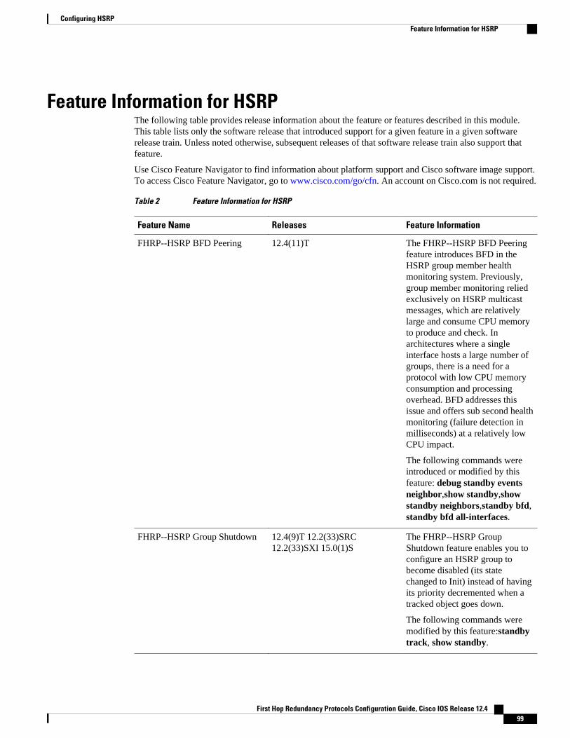
Feature Information for HSRPThe following table provides release information about the feature or features described in this module.This table lists only the software release that introduced support for a given feature in a given softwarerelease train. Unless noted otherwise, subsequent releases of that software release train also support thatfeature.
Use Cisco Feature Navigator to find information about platform support and Cisco software image support.To access Cisco Feature Navigator, go to www.cisco.com/go/cfn. An account on Cisco.com is not required.
Table 2 Feature Information for HSRP
Feature Name Releases Feature Information
FHRP--HSRP BFD Peering 12.4(11)T The FHRP--HSRP BFD Peeringfeature introduces BFD in theHSRP group member healthmonitoring system. Previously,group member monitoring reliedexclusively on HSRP multicastmessages, which are relativelylarge and consume CPU memoryto produce and check. Inarchitectures where a singleinterface hosts a large number ofgroups, there is a need for aprotocol with low CPU memoryconsumption and processingoverhead. BFD addresses thisissue and offers sub second healthmonitoring (failure detection inmilliseconds) at a relatively lowCPU impact.
The following commands wereintroduced or modified by thisfeature: debug standby eventsneighbor,show standby,showstandby neighbors,standby bfd,standby bfd all-interfaces.
FHRP--HSRP Group Shutdown 12.4(9)T 12.2(33)SRC12.2(33)SXI 15.0(1)S
The FHRP--HSRP GroupShutdown feature enables you toconfigure an HSRP group tobecome disabled (its statechanged to Init) instead of havingits priority decremented when atracked object goes down.
The following commands weremodified by this feature:standbytrack, show standby.
Configuring HSRPFeature Information for HSRP
First Hop Redundancy Protocols Configuration Guide, Cisco IOS Release 12.4 99
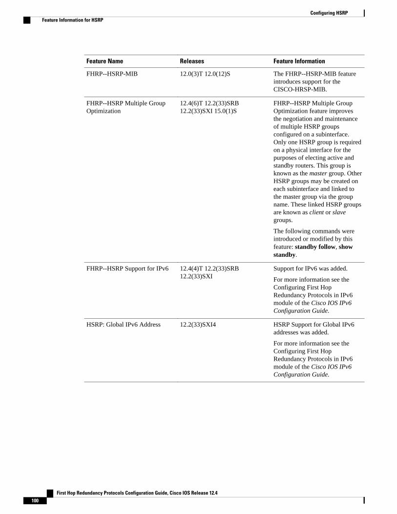
Feature Name Releases Feature Information
FHRP--HSRP-MIB 12.0(3)T 12.0(12)S The FHRP--HSRP-MIB featureintroduces support for theCISCO-HRSP-MIB.
FHRP--HSRP Multiple GroupOptimization
12.4(6)T 12.2(33)SRB12.2(33)SXI 15.0(1)S
FHRP--HSRP Multiple GroupOptimization feature improvesthe negotiation and maintenanceof multiple HSRP groupsconfigured on a subinterface.Only one HSRP group is requiredon a physical interface for thepurposes of electing active andstandby routers. This group isknown as the master group. OtherHSRP groups may be created oneach subinterface and linked tothe master group via the groupname. These linked HSRP groupsare known as client or slavegroups.
The following commands wereintroduced or modified by thisfeature: standby follow, showstandby.
FHRP--HSRP Support for IPv6 12.4(4)T 12.2(33)SRB12.2(33)SXI
Support for IPv6 was added.
For more information see theConfiguring First HopRedundancy Protocols in IPv6module of the Cisco IOS IPv6Configuration Guide.
HSRP: Global IPv6 Address 12.2(33)SXI4 HSRP Support for Global IPv6addresses was added.
For more information see theConfiguring First HopRedundancy Protocols in IPv6module of the Cisco IOS IPv6Configuration Guide.
Configuring HSRP Feature Information for HSRP
First Hop Redundancy Protocols Configuration Guide, Cisco IOS Release 12.4100
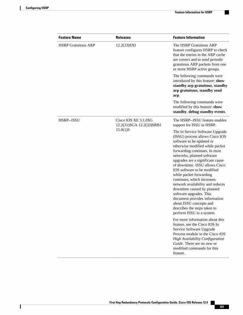
Feature Name Releases Feature Information
HSRP Gratuitous ARP 12.2(33)SXI The HSRP Gratuitous ARPfeature configures HSRP to checkthat the entries in the ARP cacheare correct and to send periodicgratuitous ARP packets from oneor more HSRP active groups.
The following commands wereintroduced by this feature: showstandby arp gratuitous, standbyarp gratuitous, standby sendarp.
The following commands weremodified by this feature: showstandby, debug standby events.
HSRP--ISSU Cisco IOS XE 3.1.0SG12.2(31)SGA 12.2(33)SRB115.0(1)S
The HSRP--ISSU feature enablessupport for ISSU in HSRP.
The In Service Software Upgrade(ISSU) process allows Cisco IOSsoftware to be updated orotherwise modified while packetforwarding continues. In mostnetworks, planned softwareupgrades are a significant causeof downtime. ISSU allows CiscoIOS software to be modifiedwhile packet forwardingcontinues, which increasesnetwork availability and reducesdowntime caused by plannedsoftware upgrades. Thisdocument provides informationabout ISSU concepts anddescribes the steps taken toperform ISSU in a system.
For more information about thisfeature, see the Cisco IOS InService Software UpgradeProcess module in the Cisco IOSHigh Availability ConfigurationGuide. There are no new ormodified commands for thisfeature.
Configuring HSRPFeature Information for HSRP
First Hop Redundancy Protocols Configuration Guide, Cisco IOS Release 12.4 101
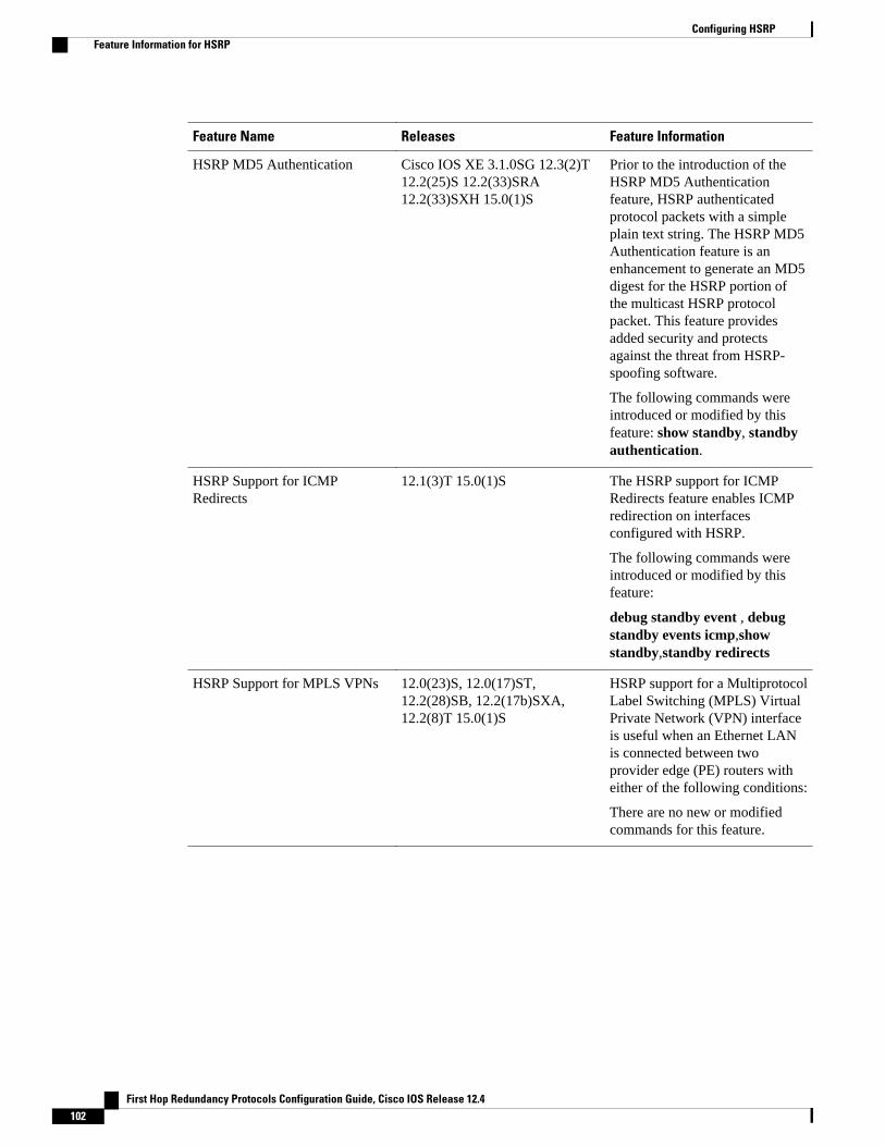
Feature Name Releases Feature Information
HSRP MD5 Authentication Cisco IOS XE 3.1.0SG 12.3(2)T12.2(25)S 12.2(33)SRA12.2(33)SXH 15.0(1)S
Prior to the introduction of theHSRP MD5 Authenticationfeature, HSRP authenticatedprotocol packets with a simpleplain text string. The HSRP MD5Authentication feature is anenhancement to generate an MD5digest for the HSRP portion ofthe multicast HSRP protocolpacket. This feature providesadded security and protectsagainst the threat from HSRP-spoofing software.
The following commands wereintroduced or modified by thisfeature: show standby, standbyauthentication.
HSRP Support for ICMPRedirects
12.1(3)T 15.0(1)S The HSRP support for ICMPRedirects feature enables ICMPredirection on interfacesconfigured with HSRP.
The following commands wereintroduced or modified by thisfeature:
debug standby event , debugstandby events icmp,showstandby,standby redirects
HSRP Support for MPLS VPNs 12.0(23)S, 12.0(17)ST,12.2(28)SB, 12.2(17b)SXA,12.2(8)T 15.0(1)S
HSRP support for a MultiprotocolLabel Switching (MPLS) VirtualPrivate Network (VPN) interfaceis useful when an Ethernet LANis connected between twoprovider edge (PE) routers witheither of the following conditions:
There are no new or modifiedcommands for this feature.
Configuring HSRP Feature Information for HSRP
First Hop Redundancy Protocols Configuration Guide, Cisco IOS Release 12.4102
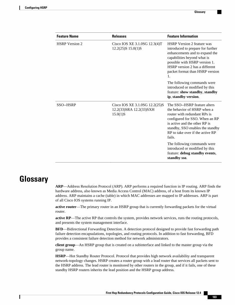
Feature Name Releases Feature Information
HSRP Version 2 Cisco IOS XE 3.1.0SG 12.3(4)T12.2(25)S 15.0(1)S
HSRP Version 2 feature wasintroduced to prepare for furtherenhancements and to expand thecapabilities beyond what ispossible with HSRP version 1.HSRP version 2 has a differentpacket format than HSRP version1.
The following commands wereintroduced or modified by thisfeature: show standby, standbyip, standby version.
SSO--HSRP Cisco IOS XE 3.1.0SG 12.2(25)S12.2(33)SRA 12.2(33)SXH15.0(1)S
The SSO--HSRP feature altersthe behavior of HSRP when arouter with redundant RPs isconfigured for SSO. When an RPis active and the other RP isstandby, SSO enables the standbyRP to take over if the active RPfails.
The following commands wereintroduced or modified by thisfeature: debug standby events,standby sso.
GlossaryARP—Address Resolution Protocol (ARP). ARP performs a required function in IP routing. ARP finds thehardware address, also known as Media Access Control (MAC) address, of a host from its known IPaddress. ARP maintains a cache (table) in which MAC addresses are mapped to IP addresses. ARP is partof all Cisco IOS systems running IP.
active router—The primary router in an HSRP group that is currently forwarding packets for the virtualrouter.
active RP—The active RP that controls the system, provides network services, runs the routing protocols,and presents the system management interface.
BFD—Bidirectional Forwarding Detection. A detection protocol designed to provide fast forwarding pathfailure detection encapsulations, topologies, and routing protocols. In addition to fast forwarding, BFDprovides a consistent failure detection method for network administrators.
client group—An HSRP group that is created on a subinterface and linked to the master group via thegroup name.
HSRP—Hot Standby Router Protocol. Protocol that provides high network availability and transparentnetwork-topology changes. HSRP creates a router group with a lead router that services all packets sent tothe HSRP address. The lead router is monitored by other routers in the group, and if it fails, one of thesestandby HSRP routers inherits the lead position and the HSRP group address.
Configuring HSRPGlossary
First Hop Redundancy Protocols Configuration Guide, Cisco IOS Release 12.4 103
ISSU—In Service Software Upgrade. A process that allows Cisco IOS software to be updated or otherwisemodified while packet forwarding continues. In most networks, planned software upgrades are a significantcause of downtime. ISSU allows Cisco IOS software to be modified while packet forwarding continues,which increases network availability and reduces downtime caused by planned software upgrades.
master group—An HSRP group that is required on a physical interface for the purposes of electing activeand standby routers.
NSF—nonstop forwarding. The ability of a router to continue to forward traffic to a router that may berecovering from a failure. Also, the ability of a router recovering from a failure to continue to correctlyforward traffic sent to it by a peer.
RF—Redundancy Facility. A structured, functional interface used to notify its clients of active and standbystate progressions and events.
RP—Route Processor. A generic term for the centralized control unit in a chassis. Platforms usually use aplatform-specific term, such as the RSP on the Cisco 7500, the PRE on the Cisco 10000, or the SUP+MSFC on the Cisco 7600.
RPR—Route Processor Redundancy. RPR provides an alternative to the High System Availability (HSA)feature. HSA enables a system to reset and use a standby Route Processor (RP) if the active RP fails. UsingRPR, you can reduce unplanned downtime because RPR enables a quicker switchover between an activeand standby RP if the active RP experiences a fatal error.
RPR+—An enhancement to RPR in which the standby RP is fully initialized.
SSO—stateful switchover. SSO refers to the implementation of Cisco IOS software that allowsapplications and features to maintain a defined state between an active and standby RP. When a switchoveroccurs, forwarding and sessions are maintained. Along with NSF, SSO makes an RP failure undetectable tothe network.
standby group—The set of routers participating in HSRP that jointly emulate a virtual router.
standby router—The backup router in an HSRP group.
standby RP—The backup RP.
switchover—An event in which system control and routing protocol execution are transferred from theactive RP to the standby RP. Switchover may be a manual operation or may be induced by a hardware orsoftware fault. Switchover may include transfer of the packet forwarding function in systems that combinesystem control and packet forwarding in an indivisible unit.
virtual IP address—The default gateway IP address configured for an HSRP group.
virtual MAC address—For Ethernet and FDDI, the automatically generated MAC address when HSRP isconfigured. The standard virtual MAC address used is: 0000.0C07.ACxy, where xy is the group number inhexadecimal. The functional address is used for Token Ring. The virtual MAC address is different forHSRP version 2.
Cisco and the Cisco logo are trademarks or registered trademarks of Cisco and/or its affiliates in the U.S.and other countries. To view a list of Cisco trademarks, go to this URL: www.cisco.com/go/trademarks.Third-party trademarks mentioned are the property of their respective owners. The use of the word partnerdoes not imply a partnership relationship between Cisco and any other company. (1110R)
Any Internet Protocol (IP) addresses and phone numbers used in this document are not intended to beactual addresses and phone numbers. Any examples, command display output, network topology diagrams,
Configuring HSRP
First Hop Redundancy Protocols Configuration Guide, Cisco IOS Release 12.4104

and other figures included in the document are shown for illustrative purposes only. Any use of actual IPaddresses or phone numbers in illustrative content is unintentional and coincidental.
Configuring HSRP
First Hop Redundancy Protocols Configuration Guide, Cisco IOS Release 12.4 105

Example: Configuring HSRP Gratuitous ARP
First Hop Redundancy Protocols Configuration Guide, Cisco IOS Release 12.4106
Configuring IRDP
The ICMP Router Discovery Protocol (IRDP) allows IPv4 hosts to locate routers that provide IPv4connectivity to other (nonlocal) IP networks. For a complete description of the IPv4 addressing commandsin this module, refer to the Cisco IOS IP Application Services Command Reference. To locatedocumentation of other commands that appear in this module, use the command reference master index,or search online.
This module explains the concepts related to IRDP and describes how to configure IRDP in a network.
• Finding Feature Information, page 107• Information About IRDP, page 107• How to Configure IRDP, page 108• Configuration Examples for IRDP, page 110• Additional References, page 110• Feature Information for IRDP, page 111
Finding Feature InformationYour software release may not support all the features documented in this module. For the latest featureinformation and caveats, see the release notes for your platform and software release. To find informationabout the features documented in this module, and to see a list of the releases in which each feature issupported, see the Feature Information Table at the end of this document.
Use Cisco Feature Navigator to find information about platform support and Cisco software image support.To access Cisco Feature Navigator, go to www.cisco.com/go/cfn. An account on Cisco.com is not required.
Information About IRDP• IRDP Overview, page 107
IRDP OverviewICMP Router Discovery Protocol (IRDP) allows hosts to locate routers that can be used as a gateway toreach IP-based devices on other networks. When the device running IRDP operates as a router, routerdiscovery packets are generated. When the device running IRDP operates as a host, router discoverypackets are received. The Cisco IRDP implementation fully conforms to the router discovery protocoloutlined in RFC 1256 ( http://www.ietf.org/rfc/rfc1256.txt ).
First Hop Redundancy Protocols Configuration Guide, Cisco IOS Release 12.4 107
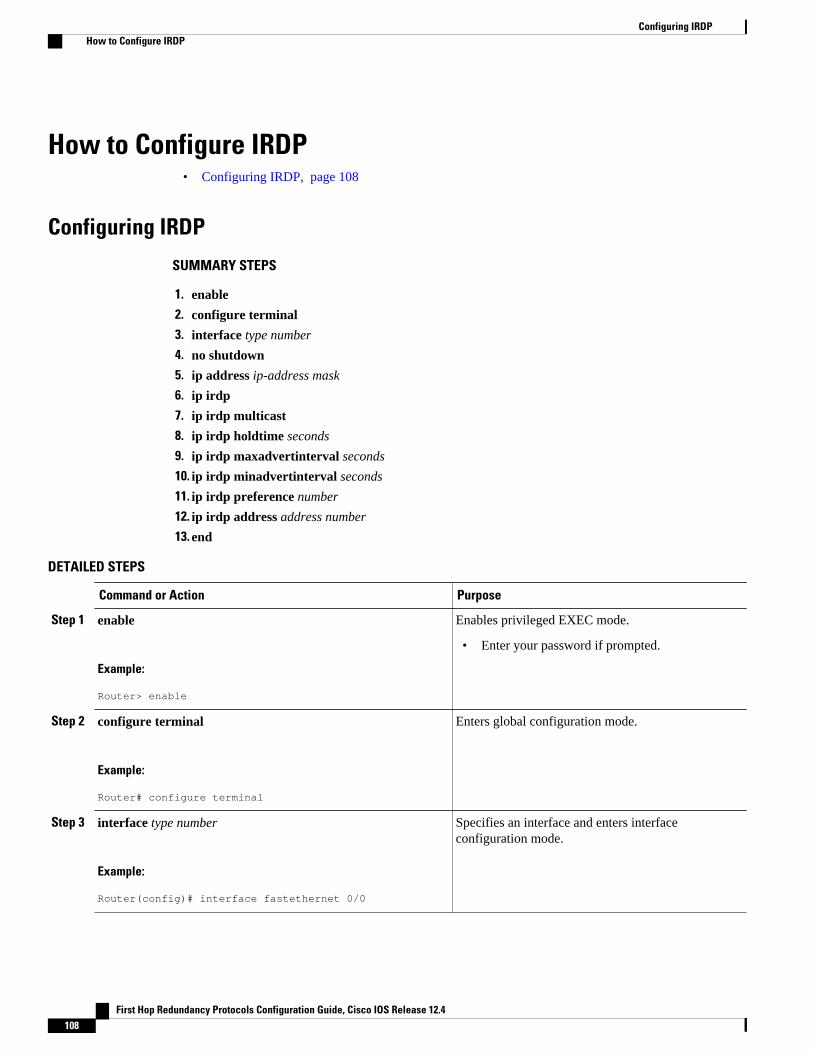
How to Configure IRDP• Configuring IRDP, page 108
Configuring IRDP
SUMMARY STEPS
1. enable
2. configure terminal
3. interface type number
4. no shutdown
5. ip address ip-address mask
6. ip irdp
7. ip irdp multicast
8. ip irdp holdtime seconds
9. ip irdp maxadvertinterval seconds
10. ip irdp minadvertinterval seconds
11. ip irdp preference number
12. ip irdp address address number
13. end
DETAILED STEPS
Command or Action Purpose
Step 1 enable
Example:
Router> enable
Enables privileged EXEC mode.
• Enter your password if prompted.
Step 2 configure terminal
Example:
Router# configure terminal
Enters global configuration mode.
Step 3 interface type number
Example:
Router(config)# interface fastethernet 0/0
Specifies an interface and enters interfaceconfiguration mode.
Configuring IRDP How to Configure IRDP
First Hop Redundancy Protocols Configuration Guide, Cisco IOS Release 12.4108
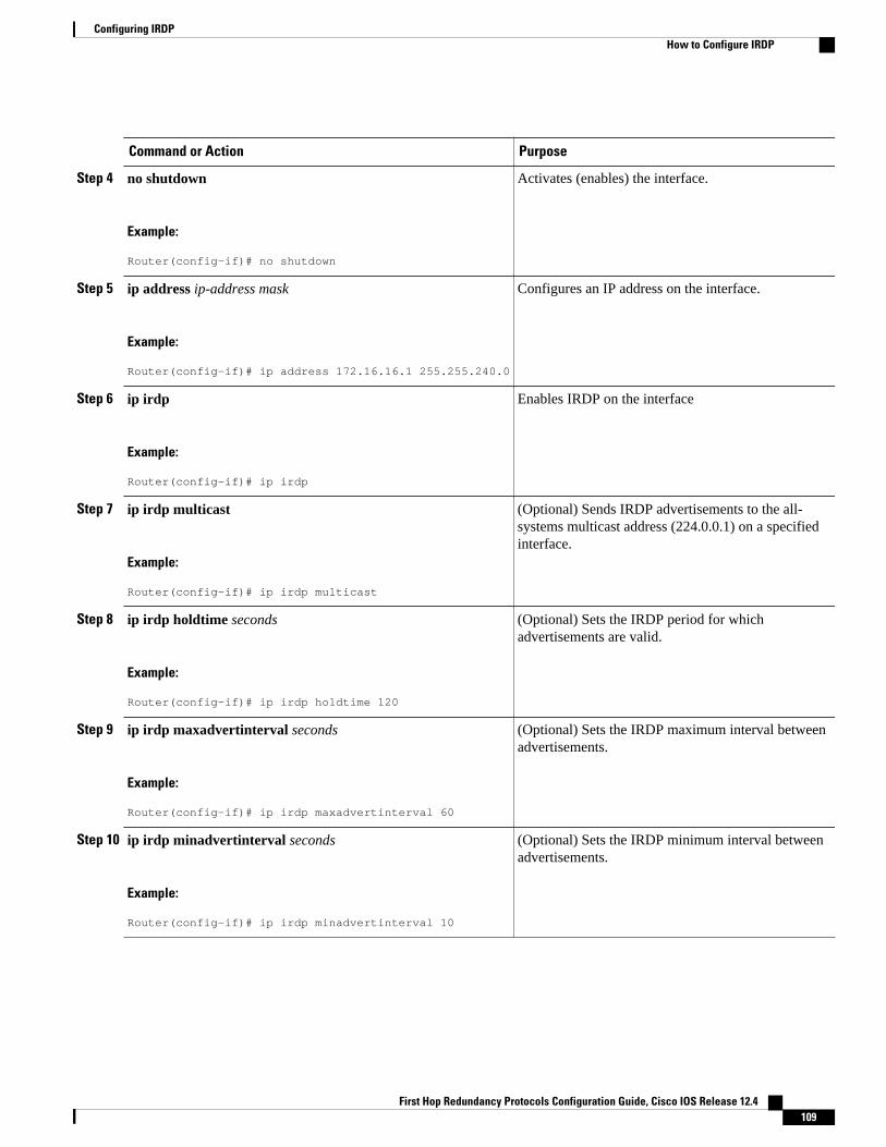
Command or Action Purpose
Step 4 no shutdown
Example:
Router(config-if)# no shutdown
Activates (enables) the interface.
Step 5 ip address ip-address mask
Example:
Router(config-if)# ip address 172.16.16.1 255.255.240.0
Configures an IP address on the interface.
Step 6 ip irdp
Example:
Router(config-if)# ip irdp
Enables IRDP on the interface
Step 7 ip irdp multicast
Example:
Router(config-if)# ip irdp multicast
(Optional) Sends IRDP advertisements to the all-systems multicast address (224.0.0.1) on a specifiedinterface.
Step 8 ip irdp holdtime seconds
Example:
Router(config-if)# ip irdp holdtime 120
(Optional) Sets the IRDP period for whichadvertisements are valid.
Step 9 ip irdp maxadvertinterval seconds
Example:
Router(config-if)# ip irdp maxadvertinterval 60
(Optional) Sets the IRDP maximum interval betweenadvertisements.
Step 10 ip irdp minadvertinterval seconds
Example:
Router(config-if)# ip irdp minadvertinterval 10
(Optional) Sets the IRDP minimum interval betweenadvertisements.
Configuring IRDPHow to Configure IRDP
First Hop Redundancy Protocols Configuration Guide, Cisco IOS Release 12.4 109
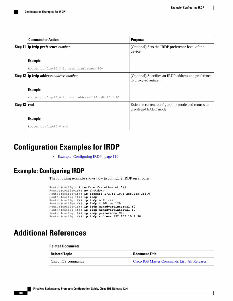
Command or Action Purpose
Step 11 ip irdp preference number
Example:
Router(config-if)# ip irdp preference 900
(Optional) Sets the IRDP preference level of thedevice.
Step 12 ip irdp address address number
Example:
Router(config-if)# ip irdp address 192.168.10.2 90
(Optional) Specifies an IRDP address and preferenceto proxy-advertise.
Step 13 end
Example:
Router(config-if)# end
Exits the current configuration mode and returns toprivileged EXEC mode.
Configuration Examples for IRDP• Example: Configuring IRDP, page 110
Example: Configuring IRDPThe following example shows how to configure IRDP on a router:
Router(config)# interface fastethernet 0/1Router(config-if)# no shutdownRouter(config-if)# ip address 172.16.10.1 255.255.255.0Router(config-if)# ip irdpRouter(config-if)# ip irdp multicastRouter(config-if)# ip irdp holdtime 120Router(config-if)# ip irdp maxadvertinterval 60Router(config-if)# ip irdp minadvertinterval 10Router(config-if)# ip irdp preference 900Router(config-if)# ip irdp address 192.168.10.2 90
Additional ReferencesRelated Documents
Related Topic Document Title
Cisco IOS commands Cisco IOS Master Commands List, All Releases
Example: Configuring IRDP Configuration Examples for IRDP
First Hop Redundancy Protocols Configuration Guide, Cisco IOS Release 12.4110
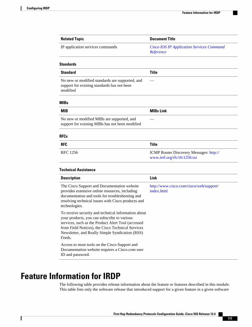
Related Topic Document Title
IP application services commands Cisco IOS IP Application Services CommandReference
Standards
Standard Title
No new or modified standards are supported, andsupport for existing standards has not beenmodified
—
MIBs
MIB MIBs Link
No new or modified MIBs are supported, andsupport for existing MIBs has not been modified
—
RFCs
RFC Title
RFC 1256 ICMP Router Discovery Messages: http://www.ietf.org/rfc/rfc1256.txt
Technical Assistance
Description Link
The Cisco Support and Documentation websiteprovides extensive online resources, includingdocumentation and tools for troubleshooting andresolving technical issues with Cisco products andtechnologies.
To receive security and technical information aboutyour products, you can subscribe to variousservices, such as the Product Alert Tool (accessedfrom Field Notices), the Cisco Technical ServicesNewsletter, and Really Simple Syndication (RSS)Feeds.
Access to most tools on the Cisco Support andDocumentation website requires a Cisco.com userID and password.
http://www.cisco.com/cisco/web/support/index.html
Feature Information for IRDPThe following table provides release information about the feature or features described in this module.This table lists only the software release that introduced support for a given feature in a given software
Configuring IRDPFeature Information for IRDP
First Hop Redundancy Protocols Configuration Guide, Cisco IOS Release 12.4 111
release train. Unless noted otherwise, subsequent releases of that software release train also support thatfeature.
Use Cisco Feature Navigator to find information about platform support and Cisco software image support.To access Cisco Feature Navigator, go to www.cisco.com/go/cfn. An account on Cisco.com is not required.
Table 3 Feature Information for IRDP
Feature Name Releases Feature Information
ICMP Router Discovery Protocol 10.0 12.2(33)SRA The ICMP Router DiscoveryProtocol (IRDP) allows IPv4hosts to locate routers thatprovide IPv4 connectivity toother (non-local) IP networks.
The following command wasintroduced or modified: ip irdp.
Cisco and the Cisco logo are trademarks or registered trademarks of Cisco and/or its affiliates in the U.S.and other countries. To view a list of Cisco trademarks, go to this URL: www.cisco.com/go/trademarks.Third-party trademarks mentioned are the property of their respective owners. The use of the word partnerdoes not imply a partnership relationship between Cisco and any other company. (1110R)
Any Internet Protocol (IP) addresses and phone numbers used in this document are not intended to beactual addresses and phone numbers. Any examples, command display output, network topology diagrams,and other figures included in the document are shown for illustrative purposes only. Any use of actual IPaddresses or phone numbers in illustrative content is unintentional and coincidental.
Configuring IRDP
First Hop Redundancy Protocols Configuration Guide, Cisco IOS Release 12.4112
Configuring VRRP
The Virtual Router Redundancy Protocol (VRRP) is an election protocol that dynamically assignsresponsibility for one or more virtual routers to the VRRP routers on a LAN, allowing several routers on amultiaccess link to utilize the same virtual IP address. A VRRP router is configured to run the VRRPprotocol in conjunction with one or more other routers attached to a LAN. In a VRRP configuration, onerouter is elected as the virtual router master, with the other routers acting as backups in case the virtualrouter master fails.
This module explains the concepts related to VRRP and describes how to configure VRRP in a network.
• Finding Feature Information, page 113• Restrictions for VRRP, page 113• Information About VRRP, page 114• How to Configure VRRP, page 119• Configuration Examples for VRRP, page 136• Additional References, page 139• Feature Information for VRRP, page 140• Glossary, page 143
Finding Feature InformationYour software release may not support all the features documented in this module. For the latest featureinformation and caveats, see the release notes for your platform and software release. To find informationabout the features documented in this module, and to see a list of the releases in which each feature issupported, see the Feature Information Table at the end of this document.
Use Cisco Feature Navigator to find information about platform support and Cisco software image support.To access Cisco Feature Navigator, go to www.cisco.com/go/cfn. An account on Cisco.com is not required.
Restrictions for VRRP• VRRP is designed for use over multiaccess, multicast, or broadcast capable Ethernet LANs. VRRP is
not intended as a replacement for existing dynamic protocols.• VRRP is supported on Ethernet, Fast Ethernet, Bridge Group Virtual Interface (BVI), and Gigabit
Ethernet interfaces, and on Multiprotocol Label Switching (MPLS) Virtual Private Networks (VPNs),VRF-aware MPLS VPNs, and VLANs.
• Because of the forwarding delay that is associated with the initialization of a BVI interface, you mustconfigure the VRRP advertise timer to a value equal to or greater than the forwarding delay on the
First Hop Redundancy Protocols Configuration Guide, Cisco IOS Release 12.4 113
BVI interface. This setting prevents a VRRP router on a recently initialized BVI interface fromunconditionally taking over the master role. Use the bridge forward-time command to set theforwarding delay on the BVI interface. Use the vrrp timers advertise command to set the VRRPadvertisement timer.
• Enhanced Object Tracking (EOT) is not stateful switchover (SSO)-aware and cannot be used withVRRP in SSO mode.
Information About VRRP• VRRP Operation, page 114
• VRRP Benefits, page 116
• Multiple Virtual Router Support, page 117
• VRRP Router Priority and Preemption, page 117
• VRRP Advertisements, page 117
• VRRP Object Tracking, page 118
• How Object Tracking Affects the Priority of a VRRP Router, page 118
• VRRP Authentication, page 118
• In Service Software Upgrade--VRRP, page 119
• VRRP Support for Stateful Switchover, page 119
VRRP OperationThere are several ways a LAN client can determine which router should be the first hop to a particularremote destination. The client can use a dynamic process or static configuration. Examples of dynamicrouter discovery are as follows:
• Proxy ARP—The client uses Address Resolution Protocol (ARP) to get the destination it wants toreach, and a router will respond to the ARP request with its own MAC address.
• Routing protocol—The client listens to dynamic routing protocol updates (for example, from RoutingInformation Protocol [RIP]) and forms its own routing table.
• ICMP Router Discovery Protocol (IRDP) client—The client runs an Internet Control MessageProtocol (ICMP) router discovery client.
The drawback to dynamic discovery protocols is that they incur some configuration and processingoverhead on the LAN client. Also, in the event of a router failure, the process of switching to another routercan be slow.
An alternative to dynamic discovery protocols is to statically configure a default router on the client. Thisapproach simplifies client configuration and processing, but creates a single point of failure. If the defaultgateway fails, the LAN client is limited to communicating only on the local IP network segment and is cutoff from the rest of the network.
VRRP can solve the static configuration problem. VRRP enables a group of routers to form a single virtualrouter. The LAN clients can then be configured with the virtual router as their default gateway. The virtualrouter, representing a group of routers, is also known as a VRRP group.
VRRP is supported on Ethernet, Fast Ethernet, BVI, and Gigabit Ethernet interfaces, and on MPLS VPNs,VRF-aware MPLS VPNs, and VLANs.
VRRP Operation Information About VRRP
First Hop Redundancy Protocols Configuration Guide, Cisco IOS Release 12.4114
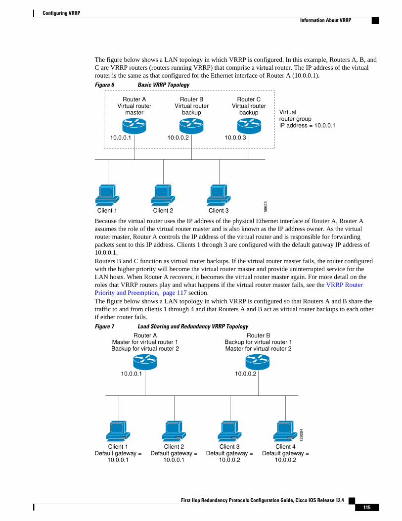
The figure below shows a LAN topology in which VRRP is configured. In this example, Routers A, B, andC are VRRP routers (routers running VRRP) that comprise a virtual router. The IP address of the virtualrouter is the same as that configured for the Ethernet interface of Router A (10.0.0.1).
Figure 6 Basic VRRP Topology
Router A Virtual router
master Virtual router group IP address = 10.0.0.1
Client 1 Client 2 Client 3
10.0.0.1
Router B Virtual router
backup
10.0.0.2
Router C Virtual router
backup
10.0.0.3
56
62
3
Because the virtual router uses the IP address of the physical Ethernet interface of Router A, Router Aassumes the role of the virtual router master and is also known as the IP address owner. As the virtualrouter master, Router A controls the IP address of the virtual router and is responsible for forwardingpackets sent to this IP address. Clients 1 through 3 are configured with the default gateway IP address of10.0.0.1.Routers B and C function as virtual router backups. If the virtual router master fails, the router configuredwith the higher priority will become the virtual router master and provide uninterrupted service for theLAN hosts. When Router A recovers, it becomes the virtual router master again. For more detail on theroles that VRRP routers play and what happens if the virtual router master fails, see the VRRP RouterPriority and Preemption, page 117 section.The figure below shows a LAN topology in which VRRP is configured so that Routers A and B share thetraffic to and from clients 1 through 4 and that Routers A and B act as virtual router backups to each otherif either router fails.
Figure 7 Load Sharing and Redundancy VRRP Topology
Router A Master for virtual router 1 Backup for virtual router 2
Router B Backup for virtual router 1 Master for virtual router 2
Client 1 Default gateway =
10.0.0.1
Client 2 Default gateway =
10.0.0.1
Client 3 Default gateway =
10.0.0.2
Client 4 Default gateway =
10.0.0.2
10.0.0.1 10.0.0.2
12
92
84
Configuring VRRPInformation About VRRP
First Hop Redundancy Protocols Configuration Guide, Cisco IOS Release 12.4 115
In this topology, two virtual routers are configured. (For more information, see the Multiple Virtual RouterSupport, page 117 section.) For virtual router 1, Router A is the owner of IP address 10.0.0.1 and virtualrouter master, and Router B is the virtual router backup to Router A. Clients 1 and 2 are configured withthe default gateway IP address of 10.0.0.1.
For virtual router 2, Router B is the owner of IP address 10.0.0.2 and virtual router master, and Router A isthe virtual router backup to Router B. Clients 3 and 4 are configured with the default gateway IP address of10.0.0.2.
VRRP Benefits
Redundancy
VRRP enables you to configure multiple routers as the default gateway router, which reduces thepossibility of a single point of failure in a network.
Load Sharing
You can configure VRRP in such a way that traffic to and from LAN clients can be shared by multiplerouters, thereby sharing the traffic load more equitably among available routers.
Multiple Virtual Routers
VRRP supports up to 255 virtual routers (VRRP groups) on a router physical interface, subject to theplatform supporting multiple MAC addresses. Multiple virtual router support enables you to implementredundancy and load sharing in your LAN topology.
Multiple IP Addresses
The virtual router can manage multiple IP addresses, including secondary IP addresses. Therefore, if youhave multiple subnets configured on an Ethernet interface, you can configure VRRP on each subnet.
Preemption
The redundancy scheme of VRRP enables you to preempt a virtual router backup that has taken over for afailing virtual router master with a higher priority virtual router backup that has become available.
Authentication
VRRP message digest 5 (MD5) algorithm authentication protects against VRRP-spoofing software anduses the industry-standard MD5 algorithm for improved reliability and security.
Advertisement Protocol
VRRP uses a dedicated Internet Assigned Numbers Authority (IANA) standard multicast address(224.0.0.18) for VRRP advertisements. This addressing scheme minimizes the number of routers that mustservice the multicasts and allows test equipment to accurately identify VRRP packets on a segment. TheIANA assigned VRRP the IP protocol number 112.
VRRP Object Tracking
VRRP object tracking provides a way to ensure the best VRRP router is the virtual router master for thegroup by altering VRRP priorities to the status of tracked objects such as the interface or IP route states.
VRRP Benefits Information About VRRP
First Hop Redundancy Protocols Configuration Guide, Cisco IOS Release 12.4116
Multiple Virtual Router SupportYou can configure up to 255 virtual routers on a router physical interface. The actual number of virtualrouters that a router interface can support depends on the following factors:
• Router processing capability• Router memory capability• Router interface support of multiple MAC addresses
In a topology where multiple virtual routers are configured on a router interface, the interface can act as amaster for one virtual router and as a backup for one or more virtual routers.
VRRP Router Priority and PreemptionAn important aspect of the VRRP redundancy scheme is VRRP router priority. Priority determines the rolethat each VRRP router plays and what happens if the virtual router master fails.
If a VRRP router owns the IP address of the virtual router and the IP address of the physical interface, thisrouter will function as a virtual router master.
Priority also determines if a VRRP router functions as a virtual router backup and the order of ascendancyto becoming a virtual router master if the virtual router master fails. You can configure the priority of eachvirtual router backup with a value of 1 through 254 using the vrrp priority command.
For example, if Router A, the virtual router master in a LAN topology, fails, an election process takes placeto determine if virtual router backups B or C should take over. If Routers B and C are configured with thepriorities of 101 and 100, respectively, Router B is elected to become virtual router master because it hasthe higher priority. If Routers B and C are both configured with the priority of 100, the virtual routerbackup with the higher IP address is elected to become the virtual router master.
By default, a preemptive scheme is enabled whereby a higher priority virtual router backup that becomesavailable takes over for the virtual router backup that was elected to become virtual router master. You candisable this preemptive scheme using the no vrrp preempt command. If preemption is disabled, the virtualrouter backup that is elected to become virtual router master remains the master until the original virtualrouter master recovers and becomes master again.
VRRP AdvertisementsThe virtual router master sends VRRP advertisements to other VRRP routers in the same group. Theadvertisements communicate the priority and state of the virtual router master. The VRRP advertisementsare encapsulated in IP packets and sent to the IP Version 4 multicast address assigned to the VRRP group.The advertisements are sent every second by default; the interval is configurable.
Although the VRRP protocol as per RFC 3768 does not support millisecond timers, Cisco routers allowyou to configure millisecond timers. You need to manually configure the millisecond timer values on boththe primary and the backup routers. The master advertisement value displayed in the show vrrp commandoutput on the backup routers is always 1 second because the packets on the backup routers do not acceptmillisecond values.
You must use millisecond timers where absolutely necessary and with careful consideration and testing.Millisecond values work only under favorable circumstances, and you must be aware that the use of themillisecond timer values restricts VRRP operation to Cisco devices only.
Multiple Virtual Router SupportInformation About VRRP
First Hop Redundancy Protocols Configuration Guide, Cisco IOS Release 12.4 117
VRRP Object TrackingObject tracking is an independent process that manages creating, monitoring, and removing tracked objectssuch as the state of the line protocol of an interface. Clients such as the Hot Standby Router Protocol(HSRP), Gateway Load Balancing Protocol (GLBP), and VRRP register their interest with specific trackedobjects and act when the state of an object changes.
Each tracked object is identified by a unique number that is specified on the tracking CLI. Client processessuch as VRRP use this number to track a specific object.
The tracking process periodically polls the tracked objects and notes any change of value. The changes inthe tracked object are communicated to interested client processes, either immediately or after a specifieddelay. The object values are reported as either up or down.
VRRP object tracking gives VRRP access to all the objects available through the tracking process. Thetracking process provides the ability to track individual objects such as a the state of an interface lineprotocol, state of an IP route, or the reachability of a route.
VRRP provides an interface to the tracking process. Each VRRP group can track multiple objects that mayaffect the priority of the VRRP router. You specify the object number to be tracked and VRRP will benotified of any change to the object. VRRP increments (or decrements) the priority of the virtual routerbased on the state of the object being tracked.
How Object Tracking Affects the Priority of a VRRP RouterThe priority of a device can change dynamically if it has been configured for object tracking and the objectthat is being tracked goes down. The tracking process periodically polls the tracked objects and notes anychange of value. The changes in the tracked object are communicated to VRRP, either immediately or aftera specified delay. The object values are reported as either up or down. Examples of objects that can betracked are the line protocol state of an interface or the reachability of an IP route. If the specified objectgoes down, the VRRP priority is reduced. The VRRP router with the higher priority can now become thevirtual router master if it has the vrrp preempt command configured. See the VRRP Object Tracking, page 118 section for more information on object tracking.
VRRP AuthenticationVRRP ignores unauthenticated VRRP protocol messages. The default authentication type is textauthentication.
You can configure VRRP text authentication, authentication using a simple MD5 key string, or MD5 keychains for authentication.
MD5 authentication provides greater security than the alternative plain text authentication scheme. MD5authentication allows each VRRP group member to use a secret key to generate a keyed MD5 hash of thepacket that is part of the outgoing packet. A keyed hash of an incoming packet is generated and if thegenerated hash does not match the hash within the incoming packet, the packet is ignored.
The key for the MD5 hash can either be given directly in the configuration using a key string or suppliedindirectly through a key chain.
A router will ignore incoming VRRP packets from routers that do not have the same authenticationconfiguration for a VRRP group. VRRP has three authentication schemes:
• No authentication• Plain text authentication
VRRP Object Tracking Information About VRRP
First Hop Redundancy Protocols Configuration Guide, Cisco IOS Release 12.4118
• MD5 authentication
VRRP packets will be rejected in any of the following cases:
• The authentication schemes differ on the router and in the incoming packet.• MD5 digests differ on the router and in the incoming packet.• Text authentication strings differ on the router and in the incoming packet.
In Service Software Upgrade--VRRPVRRP supports In Service Software Upgrade (ISSU). In Service Software Upgrade (ISSU) allows a high-availability (HA) system to run in stateful switchover (SSO) mode even when different versions of CiscoIOS software are running on the active and standby Route Processors (RPs) or line cards.
ISSU provides the ability to upgrade or downgrade from one supported Cisco IOSrelease to another whilecontinuing to forward packets and maintain sessions, thereby reducing planned outage time. The ability toupgrade or downgrade is achieved by running different software versions on the active RP and standby RPfor a short period of time to maintain state information between RPs. This feature allows the system toswitch over to a secondary RP running upgraded (or downgraded) software and continue forwardingpackets without session loss and with minimal or no packet loss. This feature is enabled by default.
For detailed information about ISSU, see theCisco IOS In Service Software Upgrade Process document inthe Cisco IOS High Availability Configuration Guide.
VRRP Support for Stateful SwitchoverWith the introduction of the VRRP Support for Stateful Switchover feature, VRRP is SSO aware. VRRPcan detect when a router is failing over to the secondary RP and continue in its current group state.
SSO functions in networking devices (usually edge devices) that support dual Route Processors (RPs). SSOprovides RP redundancy by establishing one of the RPs as the active processor and the other RP as thestandby processor. SSO also synchronizes critical state information between the RPs so that network stateinformation is dynamically maintained between RPs.
Prior to being SSO aware, if VRRP was deployed on a router with redundant RPs, a switchover of rolesbetween the active RP and the standby RP would result in the router relinquishing its activity as a VRRPgroup member and then rejoining the group as if it had been reloaded. The SSO--VRRP feature enablesVRRP to continue its activities as a group member during a switchover. VRRP state information betweenredundant RPs is maintained so that the standby RP can continue the router’s activities within the VRRPduring and after a switchover.
This feature is enabled by default. To disable this feature, use the no vrrp sso command in globalconfiguration mode.
For more information, see the Stateful Switchover document.
How to Configure VRRP• Customizing VRRP, page 120• Enabling VRRP, page 122• Disabling a VRRP Group on an Interface, page 124• Configuring VRRP Object Tracking, page 125• Configuring VRRP MD5 Authentication Using a Key String, page 127
In Service Software Upgrade--VRRPHow to Configure VRRP
First Hop Redundancy Protocols Configuration Guide, Cisco IOS Release 12.4 119
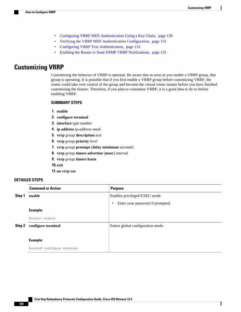
• Configuring VRRP MD5 Authentication Using a Key Chain, page 129
• Verifying the VRRP MD5 Authentication Configuration, page 132
• Configuring VRRP Text Authentication, page 133
• Enabling the Router to Send SNMP VRRP Notifications, page 135
Customizing VRRPCustomizing the behavior of VRRP is optional. Be aware that as soon as you enable a VRRP group, thatgroup is operating. It is possible that if you first enable a VRRP group before customizing VRRP, therouter could take over control of the group and become the virtual router master before you have finishedcustomizing the feature. Therefore, if you plan to customize VRRP, it is a good idea to do so beforeenabling VRRP.
SUMMARY STEPS
1. enable
2. configure terminal
3. interface type number
4. ip address ip-address mask
5. vrrp group description text
6. vrrp group priority level
7. vrrp group preempt [delay minimum seconds]
8. vrrp group timers advertise [msec] interval
9. vrrp group timers learn
10. exit
11. no vrrp sso
DETAILED STEPS
Command or Action Purpose
Step 1 enable
Example:
Router> enable
Enables privileged EXEC mode.
• Enter your password if prompted.
Step 2 configure terminal
Example:
Router# configure terminal
Enters global configuration mode.
Customizing VRRP How to Configure VRRP
First Hop Redundancy Protocols Configuration Guide, Cisco IOS Release 12.4120
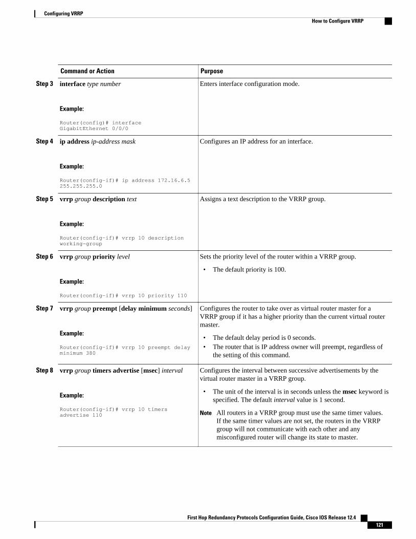
Command or Action Purpose
Step 3 interface type number
Example:
Router(config)# interface GigabitEthernet 0/0/0
Enters interface configuration mode.
Step 4 ip address ip-address mask
Example:
Router(config-if)# ip address 172.16.6.5 255.255.255.0
Configures an IP address for an interface.
Step 5 vrrp group description text
Example:
Router(config-if)# vrrp 10 description working-group
Assigns a text description to the VRRP group.
Step 6 vrrp group priority level
Example:
Router(config-if)# vrrp 10 priority 110
Sets the priority level of the router within a VRRP group.
• The default priority is 100.
Step 7 vrrp group preempt [delay minimum seconds]
Example:
Router(config-if)# vrrp 10 preempt delay minimum 380
Configures the router to take over as virtual router master for aVRRP group if it has a higher priority than the current virtual routermaster.
• The default delay period is 0 seconds.• The router that is IP address owner will preempt, regardless of
the setting of this command.
Step 8 vrrp group timers advertise [msec] interval
Example:
Router(config-if)# vrrp 10 timers advertise 110
Configures the interval between successive advertisements by thevirtual router master in a VRRP group.
• The unit of the interval is in seconds unless the msec keyword isspecified. The default interval value is 1 second.
Note All routers in a VRRP group must use the same timer values.If the same timer values are not set, the routers in the VRRPgroup will not communicate with each other and anymisconfigured router will change its state to master.
Configuring VRRPHow to Configure VRRP
First Hop Redundancy Protocols Configuration Guide, Cisco IOS Release 12.4 121
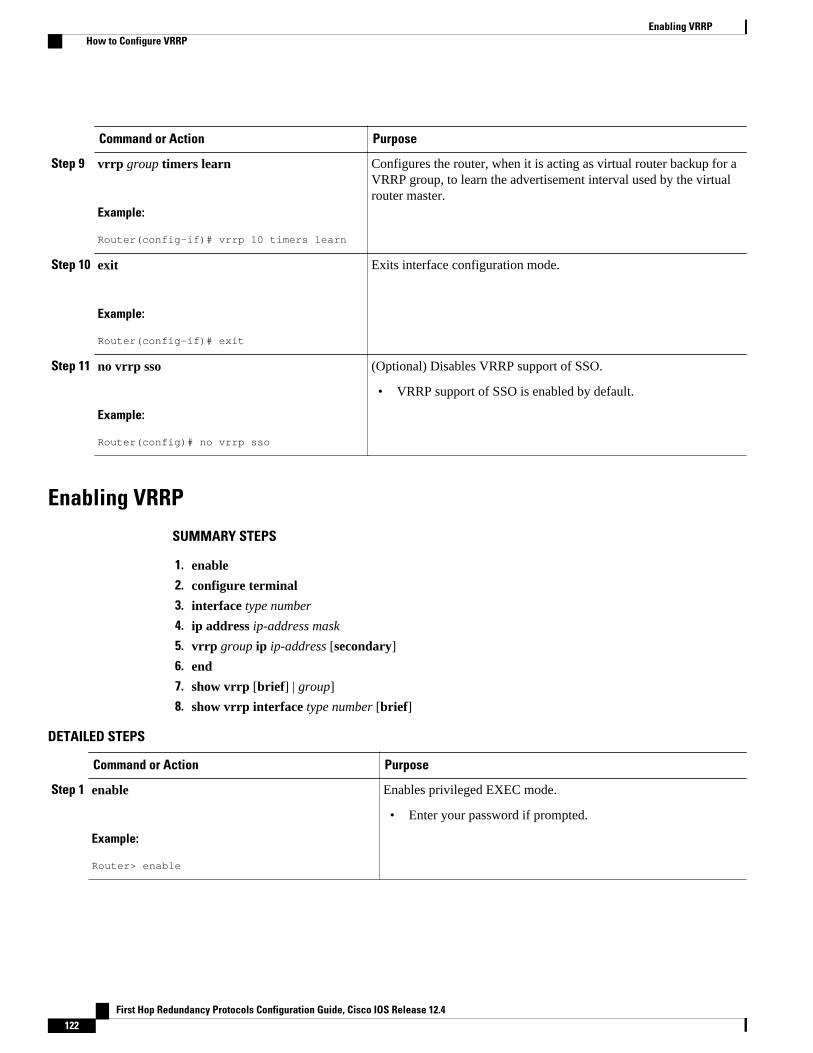
Command or Action Purpose
Step 9 vrrp group timers learn
Example:
Router(config-if)# vrrp 10 timers learn
Configures the router, when it is acting as virtual router backup for aVRRP group, to learn the advertisement interval used by the virtualrouter master.
Step 10 exit
Example:
Router(config-if)# exit
Exits interface configuration mode.
Step 11 no vrrp sso
Example:
Router(config)# no vrrp sso
(Optional) Disables VRRP support of SSO.
• VRRP support of SSO is enabled by default.
Enabling VRRP
SUMMARY STEPS
1. enable
2. configure terminal
3. interface type number
4. ip address ip-address mask
5. vrrp group ip ip-address [secondary]
6. end
7. show vrrp [brief] | group]
8. show vrrp interface type number [brief]
DETAILED STEPS
Command or Action Purpose
Step 1 enable
Example:
Router> enable
Enables privileged EXEC mode.
• Enter your password if prompted.
Enabling VRRP How to Configure VRRP
First Hop Redundancy Protocols Configuration Guide, Cisco IOS Release 12.4122
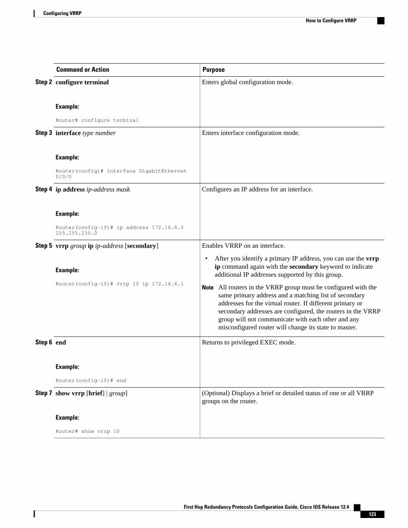
Command or Action Purpose
Step 2 configure terminal
Example:
Router# configure terminal
Enters global configuration mode.
Step 3 interface type number
Example:
Router(config)# interface GigabitEthernet 0/0/0
Enters interface configuration mode.
Step 4 ip address ip-address mask
Example:
Router(config-if)# ip address 172.16.6.5 255.255.255.0
Configures an IP address for an interface.
Step 5 vrrp group ip ip-address [secondary]
Example:
Router(config-if)# vrrp 10 ip 172.16.6.1
Enables VRRP on an interface.
• After you identify a primary IP address, you can use the vrrpip command again with the secondary keyword to indicateadditional IP addresses supported by this group.
Note All routers in the VRRP group must be configured with thesame primary address and a matching list of secondaryaddresses for the virtual router. If different primary orsecondary addresses are configured, the routers in the VRRPgroup will not communicate with each other and anymisconfigured router will change its state to master.
Step 6 end
Example:
Router(config-if)# end
Returns to privileged EXEC mode.
Step 7 show vrrp [brief] | group]
Example:
Router# show vrrp 10
(Optional) Displays a brief or detailed status of one or all VRRPgroups on the router.
Configuring VRRPHow to Configure VRRP
First Hop Redundancy Protocols Configuration Guide, Cisco IOS Release 12.4 123
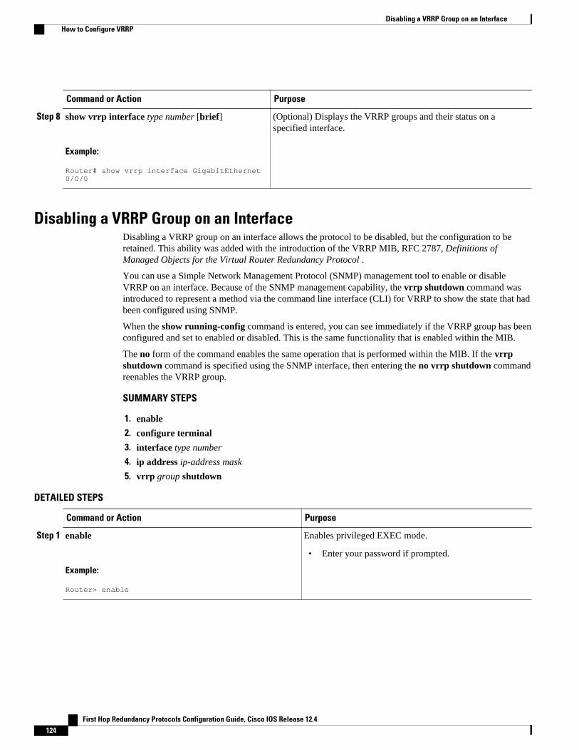
Command or Action Purpose
Step 8 show vrrp interface type number [brief]
Example:
Router# show vrrp interface GigabitEthernet 0/0/0
(Optional) Displays the VRRP groups and their status on aspecified interface.
Disabling a VRRP Group on an InterfaceDisabling a VRRP group on an interface allows the protocol to be disabled, but the configuration to beretained. This ability was added with the introduction of the VRRP MIB, RFC 2787, Definitions ofManaged Objects for the Virtual Router Redundancy Protocol .
You can use a Simple Network Management Protocol (SNMP) management tool to enable or disableVRRP on an interface. Because of the SNMP management capability, the vrrp shutdown command wasintroduced to represent a method via the command line interface (CLI) for VRRP to show the state that hadbeen configured using SNMP.
When the show running-config command is entered, you can see immediately if the VRRP group has beenconfigured and set to enabled or disabled. This is the same functionality that is enabled within the MIB.
The no form of the command enables the same operation that is performed within the MIB. If the vrrpshutdown command is specified using the SNMP interface, then entering the no vrrp shutdown commandreenables the VRRP group.
SUMMARY STEPS
1. enable
2. configure terminal
3. interface type number
4. ip address ip-address mask
5. vrrp group shutdown
DETAILED STEPS
Command or Action Purpose
Step 1 enable
Example:
Router> enable
Enables privileged EXEC mode.
• Enter your password if prompted.
Disabling a VRRP Group on an Interface How to Configure VRRP
First Hop Redundancy Protocols Configuration Guide, Cisco IOS Release 12.4124
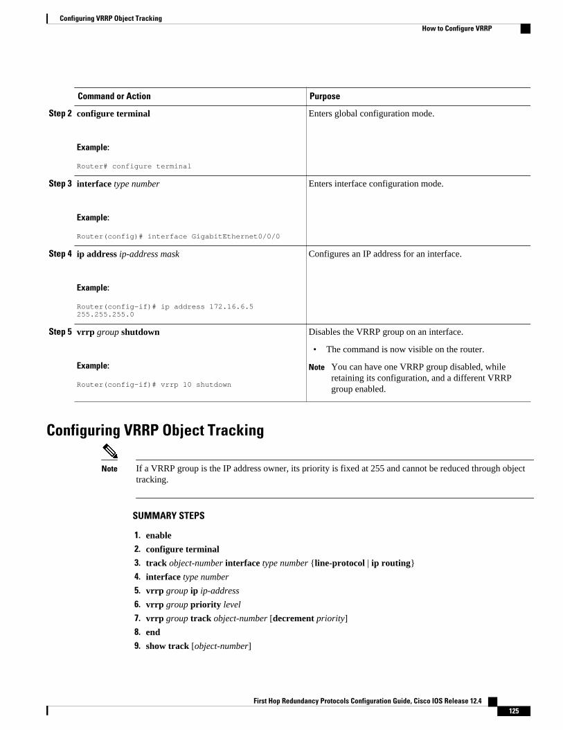
Command or Action Purpose
Step 2 configure terminal
Example:
Router# configure terminal
Enters global configuration mode.
Step 3 interface type number
Example:
Router(config)# interface GigabitEthernet0/0/0
Enters interface configuration mode.
Step 4 ip address ip-address mask
Example:
Router(config-if)# ip address 172.16.6.5 255.255.255.0
Configures an IP address for an interface.
Step 5 vrrp group shutdown
Example:
Router(config-if)# vrrp 10 shutdown
Disables the VRRP group on an interface.
• The command is now visible on the router.
Note You can have one VRRP group disabled, whileretaining its configuration, and a different VRRPgroup enabled.
Configuring VRRP Object Tracking
Note If a VRRP group is the IP address owner, its priority is fixed at 255 and cannot be reduced through objecttracking.
SUMMARY STEPS
1. enable
2. configure terminal
3. track object-number interface type number {line-protocol | ip routing}
4. interface type number
5. vrrp group ip ip-address
6. vrrp group priority level
7. vrrp group track object-number [decrement priority]
8. end
9. show track [object-number]
Configuring VRRP Object TrackingHow to Configure VRRP
First Hop Redundancy Protocols Configuration Guide, Cisco IOS Release 12.4 125
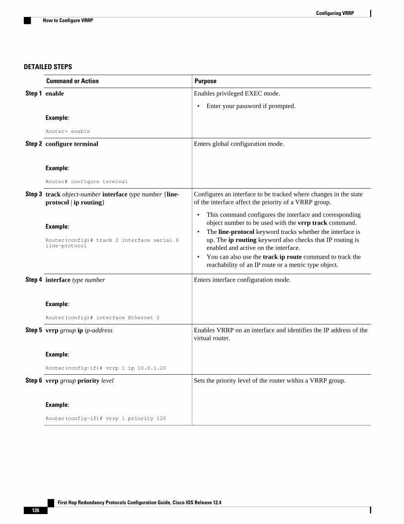
DETAILED STEPS
Command or Action Purpose
Step 1 enable
Example:
Router> enable
Enables privileged EXEC mode.
• Enter your password if prompted.
Step 2 configure terminal
Example:
Router# configure terminal
Enters global configuration mode.
Step 3 track object-number interface type number {line-protocol | ip routing}
Example:
Router(config)# track 2 interface serial 6 line-protocol
Configures an interface to be tracked where changes in the stateof the interface affect the priority of a VRRP group.
• This command configures the interface and correspondingobject number to be used with the vrrp track command.
• The line-protocol keyword tracks whether the interface isup. The ip routing keyword also checks that IP routing isenabled and active on the interface.
• You can also use the track ip route command to track thereachability of an IP route or a metric type object.
Step 4 interface type number
Example:
Router(config)# interface Ethernet 2
Enters interface configuration mode.
Step 5 vrrp group ip ip-address
Example:
Router(config-if)# vrrp 1 ip 10.0.1.20
Enables VRRP on an interface and identifies the IP address of thevirtual router.
Step 6 vrrp group priority level
Example:
Router(config-if)# vrrp 1 priority 120
Sets the priority level of the router within a VRRP group.
Configuring VRRP How to Configure VRRP
First Hop Redundancy Protocols Configuration Guide, Cisco IOS Release 12.4126
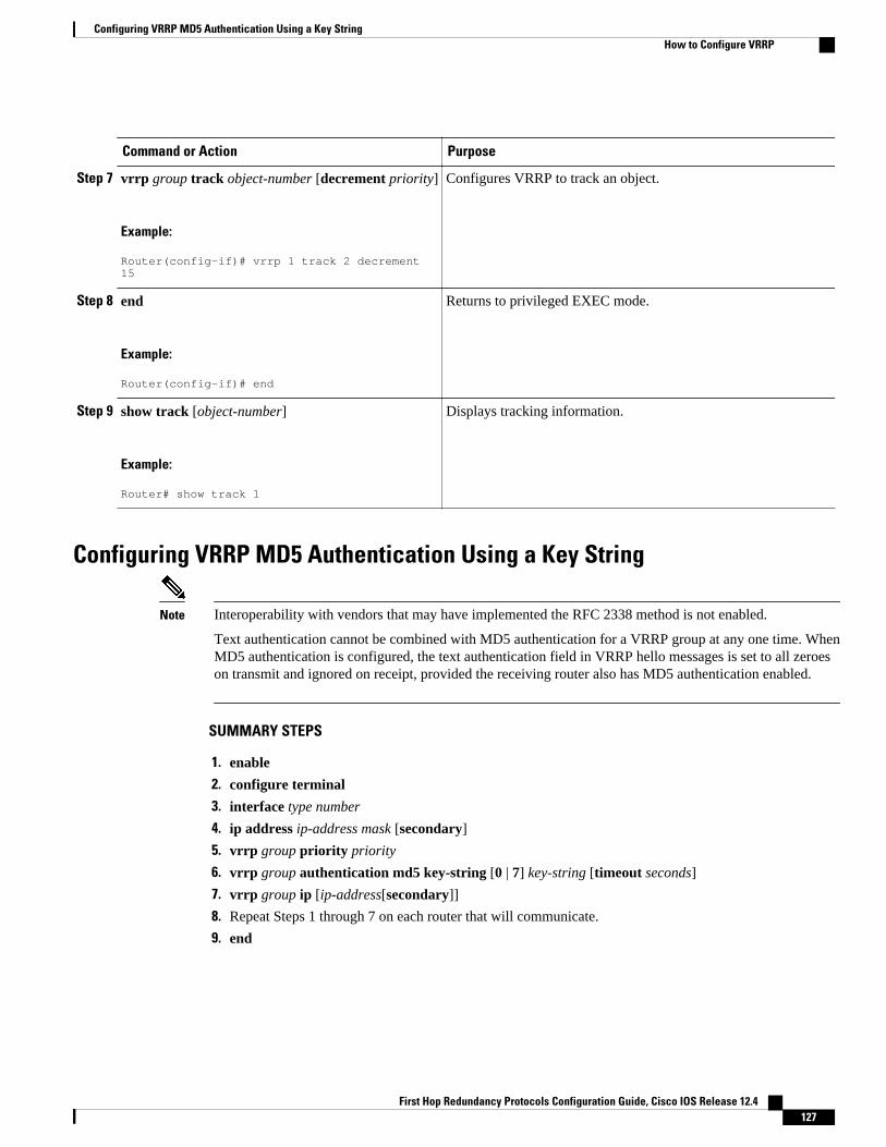
Command or Action Purpose
Step 7 vrrp group track object-number [decrement priority]
Example:
Router(config-if)# vrrp 1 track 2 decrement 15
Configures VRRP to track an object.
Step 8 end
Example:
Router(config-if)# end
Returns to privileged EXEC mode.
Step 9 show track [object-number]
Example:
Router# show track 1
Displays tracking information.
Configuring VRRP MD5 Authentication Using a Key String
Note Interoperability with vendors that may have implemented the RFC 2338 method is not enabled.
Text authentication cannot be combined with MD5 authentication for a VRRP group at any one time. WhenMD5 authentication is configured, the text authentication field in VRRP hello messages is set to all zeroeson transmit and ignored on receipt, provided the receiving router also has MD5 authentication enabled.
SUMMARY STEPS
1. enable
2. configure terminal
3. interface type number
4. ip address ip-address mask [secondary]
5. vrrp group priority priority
6. vrrp group authentication md5 key-string [0 | 7] key-string [timeout seconds]
7. vrrp group ip [ip-address[secondary]]
8. Repeat Steps 1 through 7 on each router that will communicate.
9. end
Configuring VRRP MD5 Authentication Using a Key StringHow to Configure VRRP
First Hop Redundancy Protocols Configuration Guide, Cisco IOS Release 12.4 127
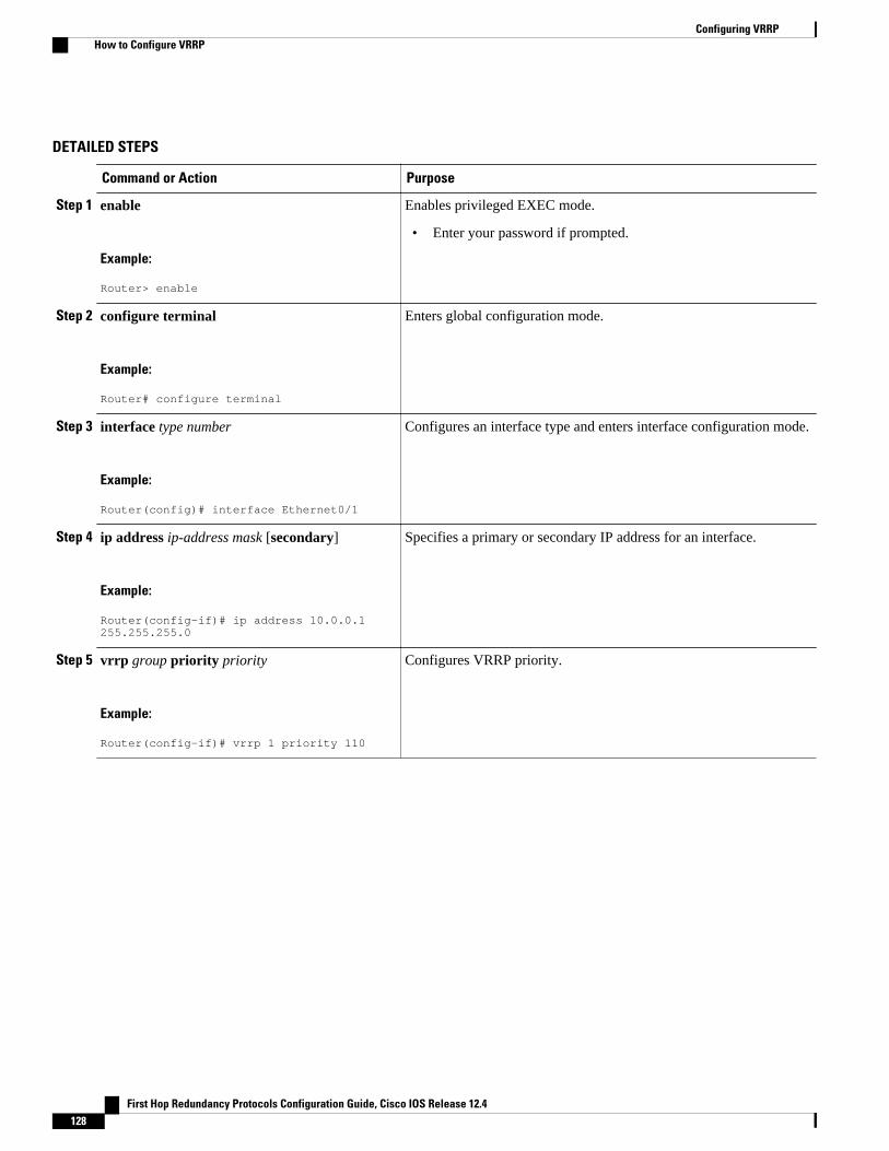
DETAILED STEPS
Command or Action Purpose
Step 1 enable
Example:
Router> enable
Enables privileged EXEC mode.
• Enter your password if prompted.
Step 2 configure terminal
Example:
Router# configure terminal
Enters global configuration mode.
Step 3 interface type number
Example:
Router(config)# interface Ethernet0/1
Configures an interface type and enters interface configuration mode.
Step 4 ip address ip-address mask [secondary]
Example:
Router(config-if)# ip address 10.0.0.1 255.255.255.0
Specifies a primary or secondary IP address for an interface.
Step 5 vrrp group priority priority
Example:
Router(config-if)# vrrp 1 priority 110
Configures VRRP priority.
Configuring VRRP How to Configure VRRP
First Hop Redundancy Protocols Configuration Guide, Cisco IOS Release 12.4128
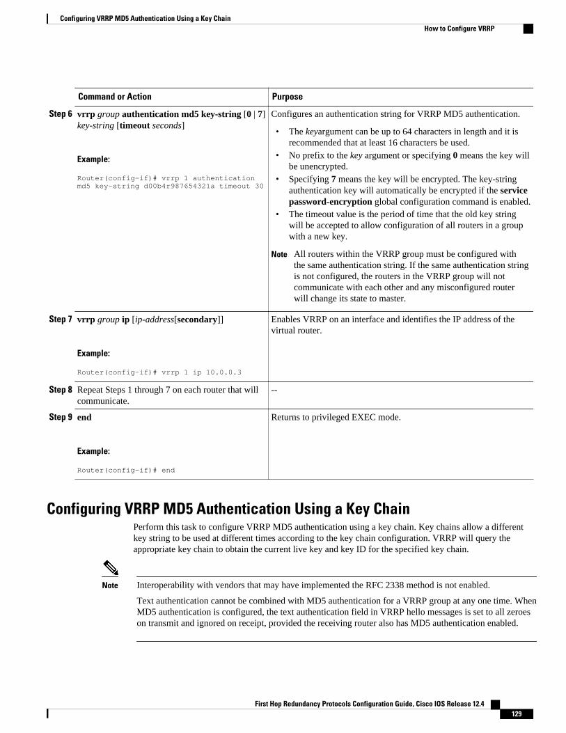
Command or Action Purpose
Step 6 vrrp group authentication md5 key-string [0 | 7]key-string [timeout seconds]
Example:
Router(config-if)# vrrp 1 authentication md5 key-string d00b4r987654321a timeout 30
Configures an authentication string for VRRP MD5 authentication.
• The keyargument can be up to 64 characters in length and it isrecommended that at least 16 characters be used.
• No prefix to the key argument or specifying 0 means the key willbe unencrypted.
• Specifying 7 means the key will be encrypted. The key-stringauthentication key will automatically be encrypted if the servicepassword-encryption global configuration command is enabled.
• The timeout value is the period of time that the old key stringwill be accepted to allow configuration of all routers in a groupwith a new key.
Note All routers within the VRRP group must be configured withthe same authentication string. If the same authentication stringis not configured, the routers in the VRRP group will notcommunicate with each other and any misconfigured routerwill change its state to master.
Step 7 vrrp group ip [ip-address[secondary]]
Example:
Router(config-if)# vrrp 1 ip 10.0.0.3
Enables VRRP on an interface and identifies the IP address of thevirtual router.
Step 8 Repeat Steps 1 through 7 on each router that willcommunicate.
--
Step 9 end
Example:
Router(config-if)# end
Returns to privileged EXEC mode.
Configuring VRRP MD5 Authentication Using a Key ChainPerform this task to configure VRRP MD5 authentication using a key chain. Key chains allow a differentkey string to be used at different times according to the key chain configuration. VRRP will query theappropriate key chain to obtain the current live key and key ID for the specified key chain.
Note Interoperability with vendors that may have implemented the RFC 2338 method is not enabled.
Text authentication cannot be combined with MD5 authentication for a VRRP group at any one time. WhenMD5 authentication is configured, the text authentication field in VRRP hello messages is set to all zeroeson transmit and ignored on receipt, provided the receiving router also has MD5 authentication enabled.
Configuring VRRP MD5 Authentication Using a Key ChainHow to Configure VRRP
First Hop Redundancy Protocols Configuration Guide, Cisco IOS Release 12.4 129
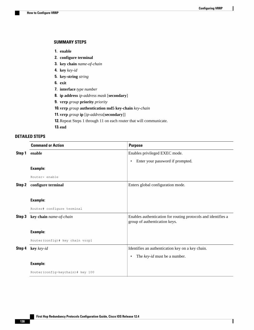
SUMMARY STEPS
1. enable
2. configure terminal
3. key chain name-of-chain
4. key key-id
5. key-string string
6. exit
7. interface type number
8. ip address ip-address mask [secondary]
9. vrrp group priority priority
10. vrrp group authentication md5 key-chain key-chain
11. vrrp group ip [ip-address[secondary]]
12. Repeat Steps 1 through 11 on each router that will communicate.
13. end
DETAILED STEPS
Command or Action Purpose
Step 1 enable
Example:
Router> enable
Enables privileged EXEC mode.
• Enter your password if prompted.
Step 2 configure terminal
Example:
Router# configure terminal
Enters global configuration mode.
Step 3 key chain name-of-chain
Example:
Router(config)# key chain vrrp1
Enables authentication for routing protocols and identifies agroup of authentication keys.
Step 4 key key-id
Example:
Router(config-keychain)# key 100
Identifies an authentication key on a key chain.
• The key-id must be a number.
Configuring VRRP How to Configure VRRP
First Hop Redundancy Protocols Configuration Guide, Cisco IOS Release 12.4130
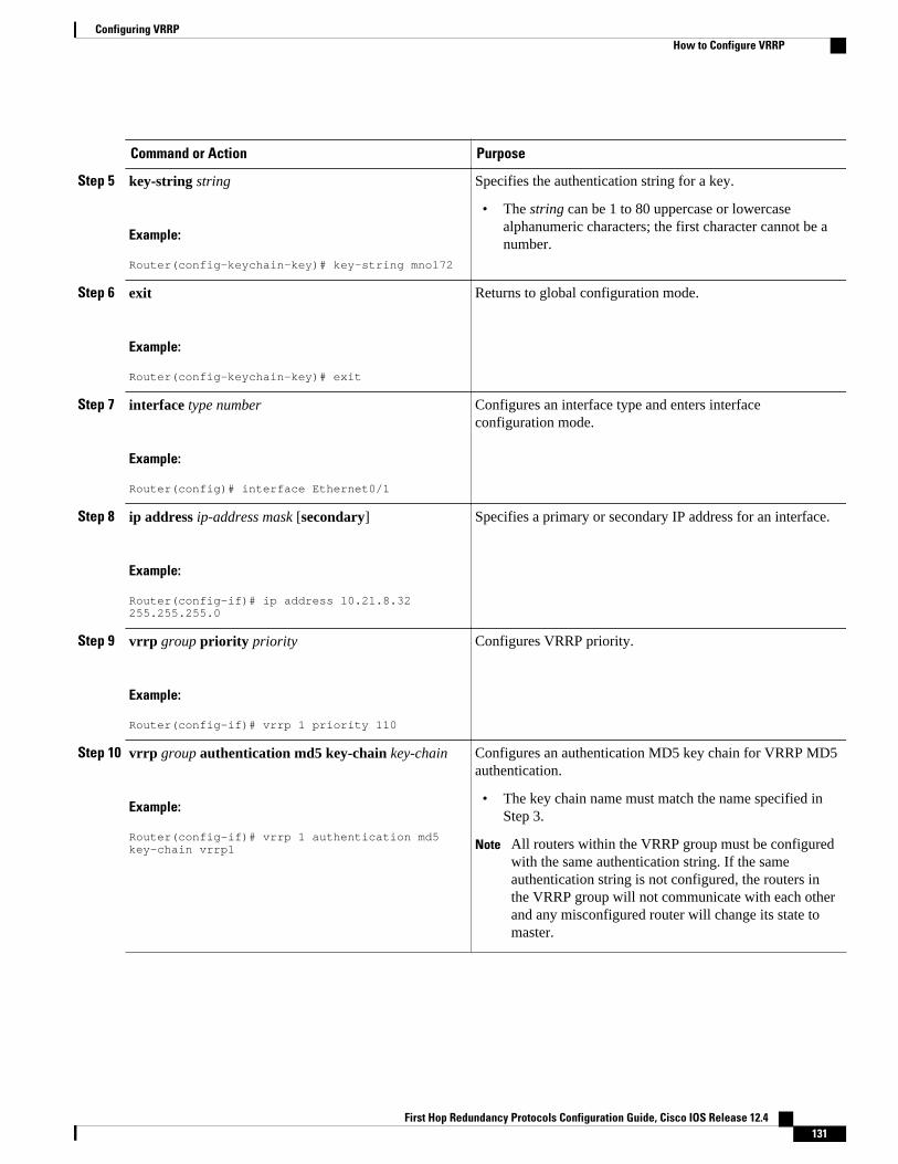
Command or Action Purpose
Step 5 key-string string
Example:
Router(config-keychain-key)# key-string mno172
Specifies the authentication string for a key.
• The string can be 1 to 80 uppercase or lowercasealphanumeric characters; the first character cannot be anumber.
Step 6 exit
Example:
Router(config-keychain-key)# exit
Returns to global configuration mode.
Step 7 interface type number
Example:
Router(config)# interface Ethernet0/1
Configures an interface type and enters interfaceconfiguration mode.
Step 8 ip address ip-address mask [secondary]
Example:
Router(config-if)# ip address 10.21.8.32 255.255.255.0
Specifies a primary or secondary IP address for an interface.
Step 9 vrrp group priority priority
Example:
Router(config-if)# vrrp 1 priority 110
Configures VRRP priority.
Step 10 vrrp group authentication md5 key-chain key-chain
Example:
Router(config-if)# vrrp 1 authentication md5 key-chain vrrp1
Configures an authentication MD5 key chain for VRRP MD5authentication.
• The key chain name must match the name specified inStep 3.
Note All routers within the VRRP group must be configuredwith the same authentication string. If the sameauthentication string is not configured, the routers inthe VRRP group will not communicate with each otherand any misconfigured router will change its state tomaster.
Configuring VRRPHow to Configure VRRP
First Hop Redundancy Protocols Configuration Guide, Cisco IOS Release 12.4 131
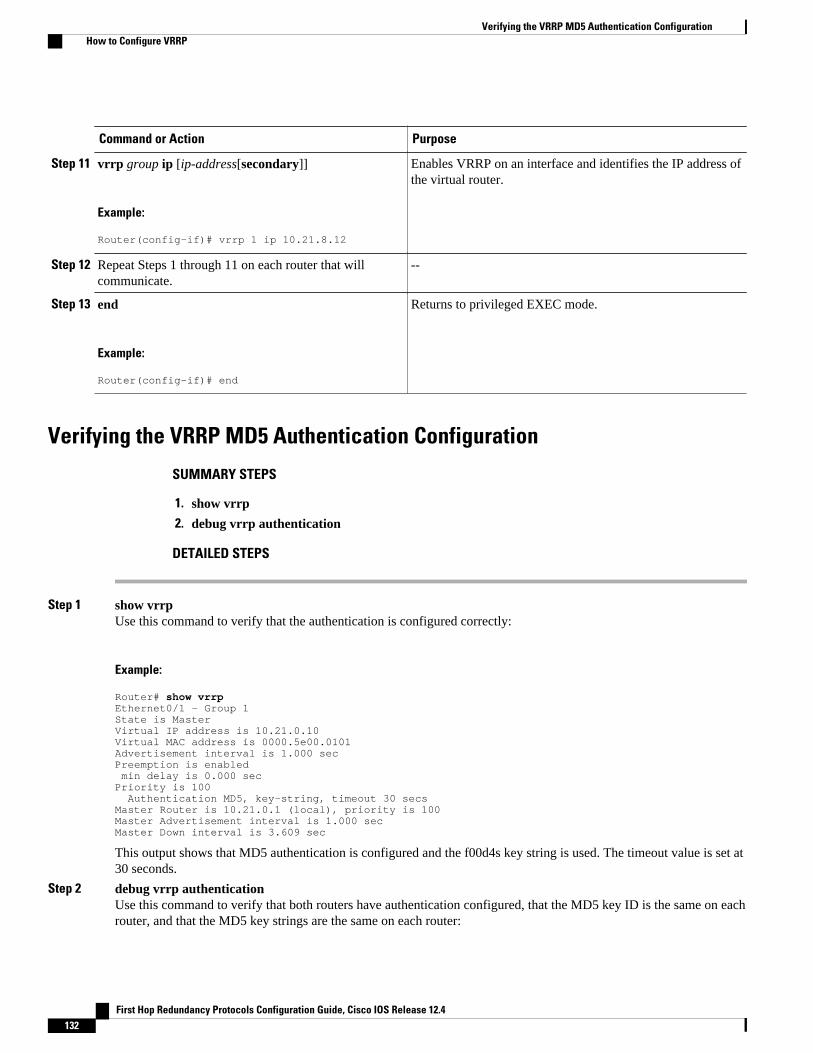
Command or Action Purpose
Step 11 vrrp group ip [ip-address[secondary]]
Example:
Router(config-if)# vrrp 1 ip 10.21.8.12
Enables VRRP on an interface and identifies the IP address ofthe virtual router.
Step 12 Repeat Steps 1 through 11 on each router that willcommunicate.
--
Step 13 end
Example:
Router(config-if)# end
Returns to privileged EXEC mode.
Verifying the VRRP MD5 Authentication Configuration
SUMMARY STEPS
1. show vrrp
2. debug vrrp authentication
DETAILED STEPS
Step 1 show vrrpUse this command to verify that the authentication is configured correctly:
Example:
Router# show vrrpEthernet0/1 - Group 1State is MasterVirtual IP address is 10.21.0.10Virtual MAC address is 0000.5e00.0101Advertisement interval is 1.000 secPreemption is enabled min delay is 0.000 secPriority is 100 Authentication MD5, key-string, timeout 30 secsMaster Router is 10.21.0.1 (local), priority is 100Master Advertisement interval is 1.000 secMaster Down interval is 3.609 sec
This output shows that MD5 authentication is configured and the f00d4s key string is used. The timeout value is set at30 seconds.
Step 2 debug vrrp authenticationUse this command to verify that both routers have authentication configured, that the MD5 key ID is the same on eachrouter, and that the MD5 key strings are the same on each router:
Verifying the VRRP MD5 Authentication Configuration How to Configure VRRP
First Hop Redundancy Protocols Configuration Guide, Cisco IOS Release 12.4132
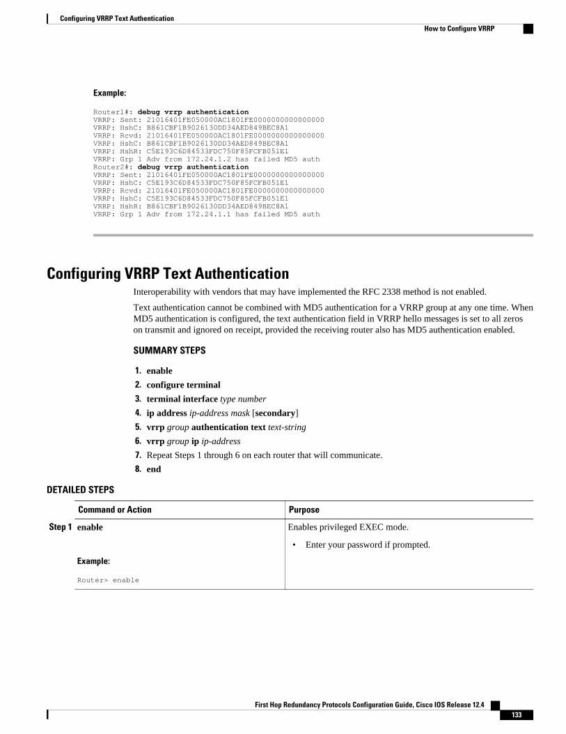
Example:
Router1#: debug vrrp authenticationVRRP: Sent: 21016401FE050000AC1801FE0000000000000000VRRP: HshC: B861CBF1B9026130DD34AED849BEC8A1VRRP: Rcvd: 21016401FE050000AC1801FE0000000000000000VRRP: HshC: B861CBF1B9026130DD34AED849BEC8A1VRRP: HshR: C5E193C6D84533FDC750F85FCFB051E1VRRP: Grp 1 Adv from 172.24.1.2 has failed MD5 authRouter2#: debug vrrp authenticationVRRP: Sent: 21016401FE050000AC1801FE0000000000000000VRRP: HshC: C5E193C6D84533FDC750F85FCFB051E1VRRP: Rcvd: 21016401FE050000AC1801FE0000000000000000VRRP: HshC: C5E193C6D84533FDC750F85FCFB051E1VRRP: HshR: B861CBF1B9026130DD34AED849BEC8A1VRRP: Grp 1 Adv from 172.24.1.1 has failed MD5 auth
Configuring VRRP Text AuthenticationInteroperability with vendors that may have implemented the RFC 2338 method is not enabled.
Text authentication cannot be combined with MD5 authentication for a VRRP group at any one time. WhenMD5 authentication is configured, the text authentication field in VRRP hello messages is set to all zeroson transmit and ignored on receipt, provided the receiving router also has MD5 authentication enabled.
SUMMARY STEPS
1. enable
2. configure terminal
3. terminal interface type number
4. ip address ip-address mask [secondary]
5. vrrp group authentication text text-string
6. vrrp group ip ip-address
7. Repeat Steps 1 through 6 on each router that will communicate.
8. end
DETAILED STEPS
Command or Action Purpose
Step 1 enable
Example:
Router> enable
Enables privileged EXEC mode.
• Enter your password if prompted.
Configuring VRRP Text AuthenticationHow to Configure VRRP
First Hop Redundancy Protocols Configuration Guide, Cisco IOS Release 12.4 133
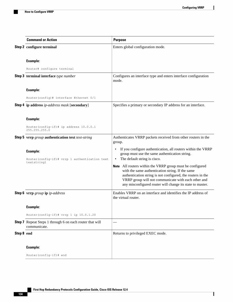
Command or Action Purpose
Step 2 configure terminal
Example:
Router# configure terminal
Enters global configuration mode.
Step 3 terminal interface type number
Example:
Router(config)# interface Ethernet 0/1
Configures an interface type and enters interface configurationmode.
Step 4 ip address ip-address mask [secondary]
Example:
Router(config-if)# ip address 10.0.0.1 255.255.255.0
Specifies a primary or secondary IP address for an interface.
Step 5 vrrp group authentication text text-string
Example:
Router(config-if)# vrrp 1 authentication text textstring1
Authenticates VRRP packets received from other routers in thegroup.
• If you configure authentication, all routers within the VRRPgroup must use the same authentication string.
• The default string is cisco.
Note All routers within the VRRP group must be configuredwith the same authentication string. If the sameauthentication string is not configured, the routers in theVRRP group will not communicate with each other andany misconfigured router will change its state to master.
Step 6 vrrp group ip ip-address
Example:
Router(config-if)# vrrp 1 ip 10.0.1.20
Enables VRRP on an interface and identifies the IP address ofthe virtual router.
Step 7 Repeat Steps 1 through 6 on each router that willcommunicate.
—
Step 8 end
Example:
Router(config-if)# end
Returns to privileged EXEC mode.
Configuring VRRP How to Configure VRRP
First Hop Redundancy Protocols Configuration Guide, Cisco IOS Release 12.4134
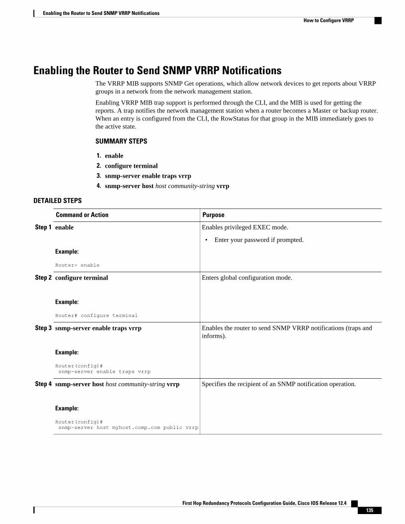
Enabling the Router to Send SNMP VRRP NotificationsThe VRRP MIB supports SNMP Get operations, which allow network devices to get reports about VRRPgroups in a network from the network management station.
Enabling VRRP MIB trap support is performed through the CLI, and the MIB is used for getting thereports. A trap notifies the network management station when a router becomes a Master or backup router.When an entry is configured from the CLI, the RowStatus for that group in the MIB immediately goes tothe active state.
SUMMARY STEPS
1. enable
2. configure terminal
3. snmp-server enable traps vrrp
4. snmp-server host host community-string vrrp
DETAILED STEPS
Command or Action Purpose
Step 1 enable
Example:
Router> enable
Enables privileged EXEC mode.
• Enter your password if prompted.
Step 2 configure terminal
Example:
Router# configure terminal
Enters global configuration mode.
Step 3 snmp-server enable traps vrrp
Example:
Router(config)# snmp-server enable traps vrrp
Enables the router to send SNMP VRRP notifications (traps andinforms).
Step 4 snmp-server host host community-string vrrp
Example:
Router(config)# snmp-server host myhost.comp.com public vrrp
Specifies the recipient of an SNMP notification operation.
Enabling the Router to Send SNMP VRRP NotificationsHow to Configure VRRP
First Hop Redundancy Protocols Configuration Guide, Cisco IOS Release 12.4 135
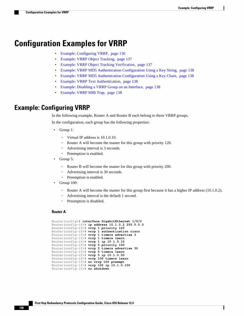
Configuration Examples for VRRP• Example: Configuring VRRP, page 136
• Example: VRRP Object Tracking, page 137
• Example: VRRP Object Tracking Verification, page 137
• Example: VRRP MD5 Authentication Configuration Using a Key String, page 138
• Example: VRRP MD5 Authentication Configuration Using a Key Chain, page 138
• Example: VRRP Text Authentication, page 138
• Example: Disabling a VRRP Group on an Interface, page 138
• Example: VRRP MIB Trap, page 138
Example: Configuring VRRPIn the following example, Router A and Router B each belong to three VRRP groups.
In the configuration, each group has the following properties:
• Group 1:
◦ Virtual IP address is 10.1.0.10.◦ Router A will become the master for this group with priority 120.◦ Advertising interval is 3 seconds.◦ Preemption is enabled.
• Group 5:
◦ Router B will become the master for this group with priority 200.◦ Advertising interval is 30 seconds.◦ Preemption is enabled.
• Group 100:
◦ Router A will become the master for this group first because it has a higher IP address (10.1.0.2).◦ Advertising interval is the default 1 second.◦ Preemption is disabled.
Router A
Router(config)# interface GigabitEthernet 1/0/0 Router(config-if)# ip address 10.1.0.2 255.0.0.0 Router(config-if)# vrrp 1 priority 120 Router(config-if)# vrrp 1 authentication cisco Router(config-if)# vrrp 1 timers advertise 3 Router(config-if)# vrrp 1 timers learn Router(config-if)# vrrp 1 ip 10.1.0.10 Router(config-if)# vrrp 5 priority 100 Router(config-if)# vrrp 5 timers advertise 30Router(config-if)# vrrp 5 timers learnRouter(config-if)# vrrp 5 ip 10.1.0.50 Router(config-if)# vrrp 100 timers learnRouter(config-if)# no vrrp 100 preempt Router(config-if)# vrrp 100 ip 10.1.0.100Router(config-if)# no shutdown
Example: Configuring VRRP Configuration Examples for VRRP
First Hop Redundancy Protocols Configuration Guide, Cisco IOS Release 12.4136
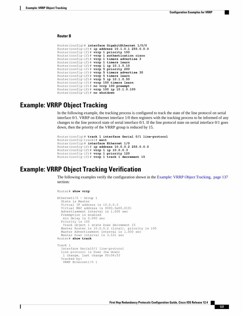
Router B
Router(config)# interface GigabitEthernet 1/0/0 Router(config-if)# ip address 10.1.0.1 255.0.0.0 Router(config-if)# vrrp 1 priority 100 Router(config-if)# vrrp 1 authentication cisco Router(config-if)# vrrp 1 timers advertise 3 Router(config-if)# vrrp 1 timers learn Router(config-if)# vrrp 1 ip 10.1.0.10 Router(config-if)# vrrp 5 priority 200 Router(config-if)# vrrp 5 timers advertise 30Router(config-if)# vrrp 5 timers learnRouter(config-if)# vrrp 5 ip 10.1.0.50 Router(config-if)# vrrp 100 timers learnRouter(config-if)# no vrrp 100 preempt Router(config-if)# vrrp 100 ip 10.1.0.100Router(config-if)# no shutdown
Example: VRRP Object TrackingIn the following example, the tracking process is configured to track the state of the line protocol on serialinterface 0/1. VRRP on Ethernet interface 1/0 then registers with the tracking process to be informed of anychanges to the line protocol state of serial interface 0/1. If the line protocol state on serial interface 0/1 goesdown, then the priority of the VRRP group is reduced by 15.
Router(config)# track 1 interface Serial 0/1 line-protocolRouter(config-track)# exitRouter(config)# interface Ethernet 1/0Router(config-if)# ip address 10.0.0.2 255.0.0.0Router(config-if)# vrrp 1 ip 10.0.0.3Router(config-if)# vrrp 1 priority 120Router(config-if)# vrrp 1 track 1 decrement 15
Example: VRRP Object Tracking VerificationThe following examples verify the configuration shown in the Example: VRRP Object Tracking, page 137section:
Router# show vrrp
Ethernet1/0 - Group 1 State is Master Virtual IP address is 10.0.0.3 Virtual MAC address is 0000.5e00.0101 Advertisement interval is 1.000 sec Preemption is enabled min delay is 0.000 sec Priority is 105 Track object 1 state Down decrement 15 Master Router is 10.0.0.2 (local), priority is 105 Master Advertisement interval is 1.000 sec Master Down interval is 3.531 secRouter# show track
Track 1 Interface Serial0/1 line-protocol Line protocol is Down (hw down) 1 change, last change 00:06:53 Tracked by: VRRP Ethernet1/0 1
Example: VRRP Object TrackingConfiguration Examples for VRRP
First Hop Redundancy Protocols Configuration Guide, Cisco IOS Release 12.4 137
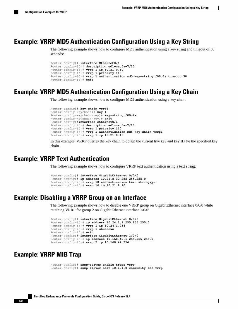
Example: VRRP MD5 Authentication Configuration Using a Key StringThe following example shows how to configure MD5 authentication using a key string and timeout of 30seconds:
Router(config)# interface Ethernet0/1Router(config-if)# description ed1-cat5a-7/10Router(config-if)# vrrp 1 ip 10.21.0.10Router(config-if)# vrrp 1 priority 110Router(config-if)# vrrp 1 authentication md5 key-string f00c4s timeout 30Router(config-if)# exit
Example: VRRP MD5 Authentication Configuration Using a Key ChainThe following example shows how to configure MD5 authentication using a key chain:
Router(config)# key chain vrrp1Router(config-keychain)# key 1Router(config-keychain-key)# key-string f00c4sRouter(config-keychain-key)# exitRouter(config)#interface ethernet0/1Router(config-if)# description ed1-cat5a-7/10Router(config-if)# vrrp 1 priority 110Router(config-if)# vrrp 1 authentication md5 key-chain vrrp1Router(config-if)# vrrp 1 ip 10.21.0.10
In this example, VRRP queries the key chain to obtain the current live key and key ID for the specified keychain.
Example: VRRP Text AuthenticationThe following example shows how to configure VRRP text authentication using a text string:
Router(config)# interface GigabitEthernet 0/0/0Router(config)# ip address 10.21.8.32 255.255.255.0Router(config-if)# vrrp 10 authentication text stringxyzRouter(config-if)# vrrp 10 ip 10.21.8.10
Example: Disabling a VRRP Group on an InterfaceThe following example shows how to disable one VRRP group on GigabitEthernet interface 0/0/0 whileretaining VRRP for group 2 on GigabitEthernet interface 1/0/0:
Router(config)# interface GigabitEthernet 0/0/0Router(config-if)# ip address 10.24.1.1 255.255.255.0Router(config-if)# vrrp 1 ip 10.24.1.254Router(config-if)# vrrp 1 shutdownRouter(config-if)# exitRouter(config)# interface GigabitEthernet 1/0/0Router(config-if)# ip address 10.168.42.1 255.255.255.0Router(config-if)# vrrp 2 ip 10.168.42.254
Example: VRRP MIB TrapRouter(config)# snmp-server enable traps vrrpRouter(config)# snmp-server host 10.1.1.0 community abc vrrp
Example: VRRP MD5 Authentication Configuration Using a Key String Configuration Examples for VRRP
First Hop Redundancy Protocols Configuration Guide, Cisco IOS Release 12.4138
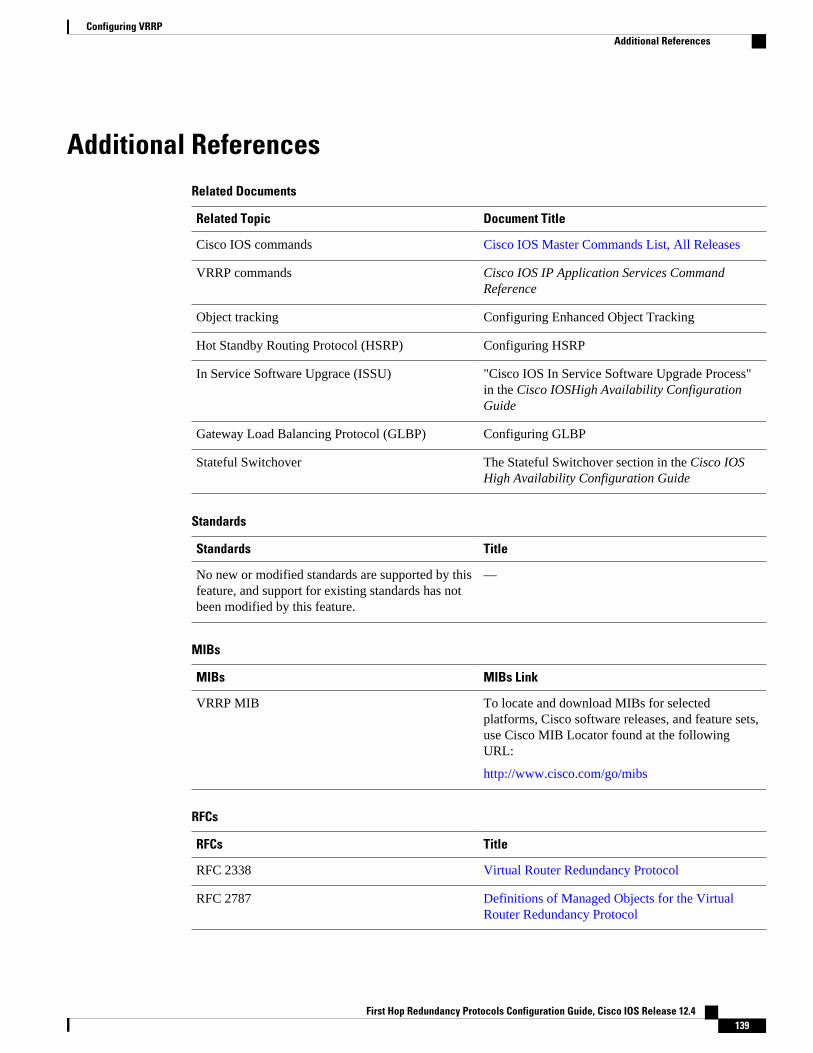
Additional ReferencesRelated Documents
Related Topic Document Title
Cisco IOS commands Cisco IOS Master Commands List, All Releases
VRRP commands Cisco IOS IP Application Services CommandReference
Object tracking Configuring Enhanced Object Tracking
Hot Standby Routing Protocol (HSRP) Configuring HSRP
In Service Software Upgrace (ISSU) "Cisco IOS In Service Software Upgrade Process"in the Cisco IOSHigh Availability ConfigurationGuide
Gateway Load Balancing Protocol (GLBP) Configuring GLBP
Stateful Switchover The Stateful Switchover section in the Cisco IOSHigh Availability Configuration Guide
Standards
Standards Title
No new or modified standards are supported by thisfeature, and support for existing standards has notbeen modified by this feature.
—
MIBs
MIBs MIBs Link
VRRP MIB To locate and download MIBs for selectedplatforms, Cisco software releases, and feature sets,use Cisco MIB Locator found at the followingURL:
http://www.cisco.com/go/mibs
RFCs
RFCs Title
RFC 2338 Virtual Router Redundancy Protocol
RFC 2787 Definitions of Managed Objects for the VirtualRouter Redundancy Protocol
Configuring VRRPAdditional References
First Hop Redundancy Protocols Configuration Guide, Cisco IOS Release 12.4 139
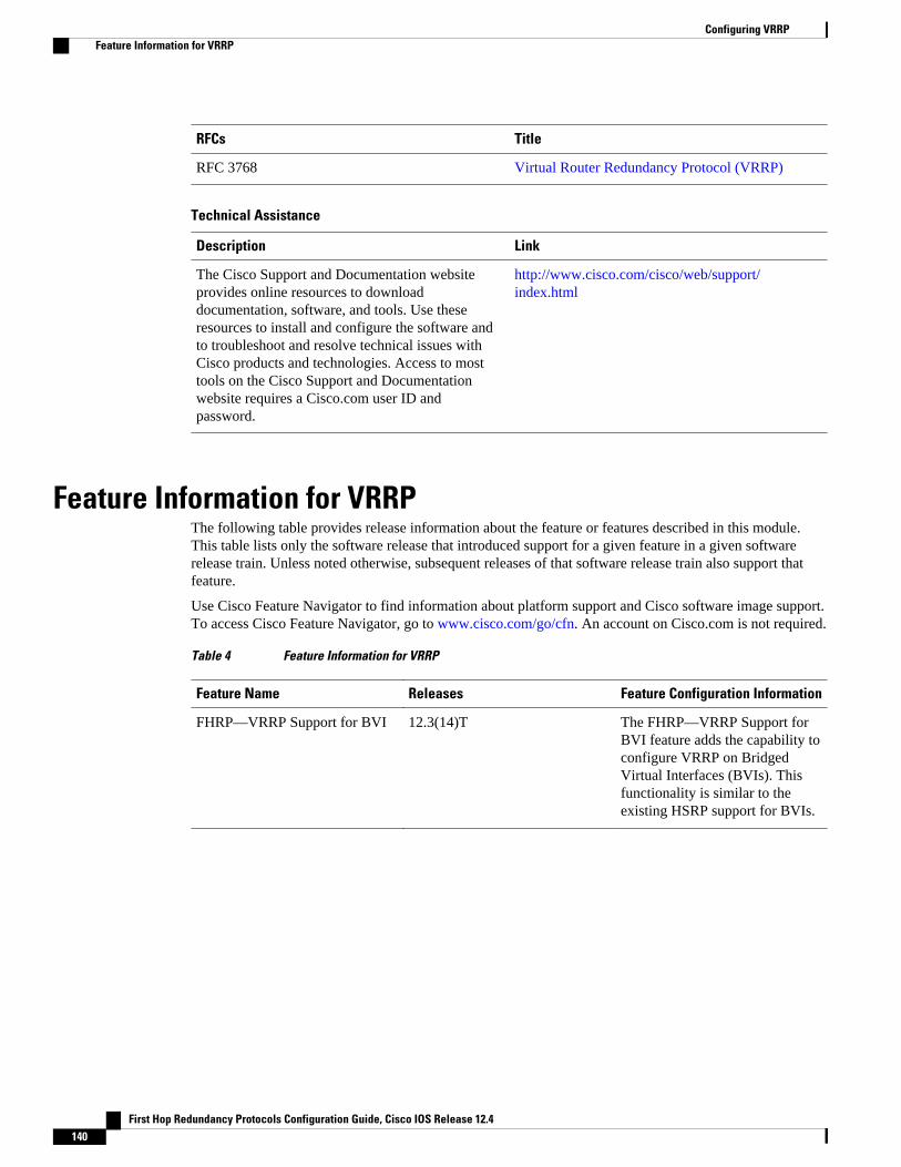
RFCs Title
RFC 3768 Virtual Router Redundancy Protocol (VRRP)
Technical Assistance
Description Link
The Cisco Support and Documentation websiteprovides online resources to downloaddocumentation, software, and tools. Use theseresources to install and configure the software andto troubleshoot and resolve technical issues withCisco products and technologies. Access to mosttools on the Cisco Support and Documentationwebsite requires a Cisco.com user ID andpassword.
http://www.cisco.com/cisco/web/support/index.html
Feature Information for VRRPThe following table provides release information about the feature or features described in this module.This table lists only the software release that introduced support for a given feature in a given softwarerelease train. Unless noted otherwise, subsequent releases of that software release train also support thatfeature.
Use Cisco Feature Navigator to find information about platform support and Cisco software image support.To access Cisco Feature Navigator, go to www.cisco.com/go/cfn. An account on Cisco.com is not required.
Table 4 Feature Information for VRRP
Feature Name Releases Feature Configuration Information
FHRP—VRRP Support for BVI 12.3(14)T The FHRP—VRRP Support forBVI feature adds the capability toconfigure VRRP on BridgedVirtual Interfaces (BVIs). Thisfunctionality is similar to theexisting HSRP support for BVIs.
Configuring VRRP Feature Information for VRRP
First Hop Redundancy Protocols Configuration Guide, Cisco IOS Release 12.4140
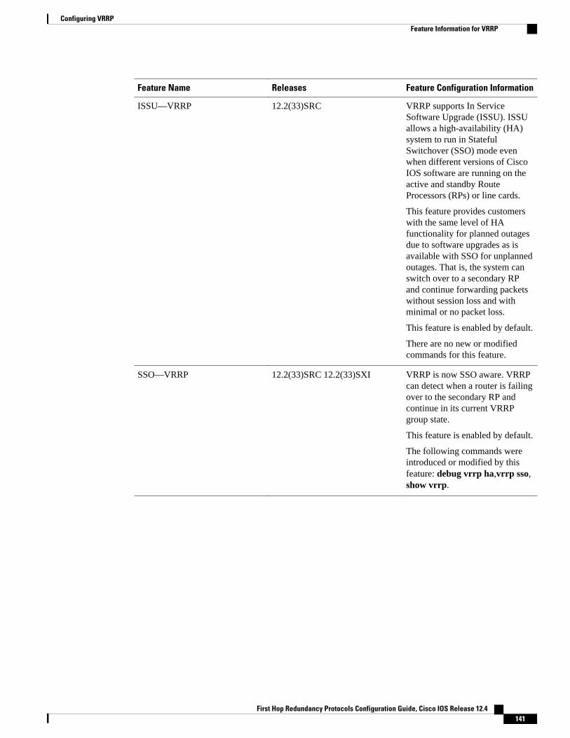
Feature Name Releases Feature Configuration Information
ISSU—VRRP 12.2(33)SRC VRRP supports In ServiceSoftware Upgrade (ISSU). ISSUallows a high-availability (HA)system to run in StatefulSwitchover (SSO) mode evenwhen different versions of CiscoIOS software are running on theactive and standby RouteProcessors (RPs) or line cards.
This feature provides customerswith the same level of HAfunctionality for planned outagesdue to software upgrades as isavailable with SSO for unplannedoutages. That is, the system canswitch over to a secondary RPand continue forwarding packetswithout session loss and withminimal or no packet loss.
This feature is enabled by default.
There are no new or modifiedcommands for this feature.
SSO—VRRP 12.2(33)SRC 12.2(33)SXI VRRP is now SSO aware. VRRPcan detect when a router is failingover to the secondary RP andcontinue in its current VRRPgroup state.
This feature is enabled by default.
The following commands wereintroduced or modified by thisfeature: debug vrrp ha,vrrp sso,show vrrp.
Configuring VRRPFeature Information for VRRP
First Hop Redundancy Protocols Configuration Guide, Cisco IOS Release 12.4 141
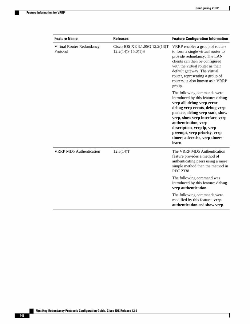
Feature Name Releases Feature Configuration Information
Virtual Router RedundancyProtocol
Cisco IOS XE 3.1.0SG 12.2(13)T12.2(14)S 15.0(1)S
VRRP enables a group of routersto form a single virtual router toprovide redundancy. The LANclients can then be configuredwith the virtual router as theirdefault gateway. The virtualrouter, representing a group ofrouters, is also known as a VRRPgroup.
The following commands wereintroduced by this feature: debugvrrp all, debug vrrp error,debug vrrp events, debug vrrppackets, debug vrrp state, showvrrp, show vrrp interface, vrrpauthentication, vrrpdescription, vrrp ip, vrrppreempt, vrrp priority, vrrptimers advertise, vrrp timerslearn.
VRRP MD5 Authentication 12.3(14)T The VRRP MD5 Authenticationfeature provides a method ofauthenticating peers using a moresimple method than the method inRFC 2338.
The following command wasintroduced by this feature: debugvrrp authentication.
The following commands weremodified by this feature: vrrpauthentication and show vrrp.
Configuring VRRP Feature Information for VRRP
First Hop Redundancy Protocols Configuration Guide, Cisco IOS Release 12.4142
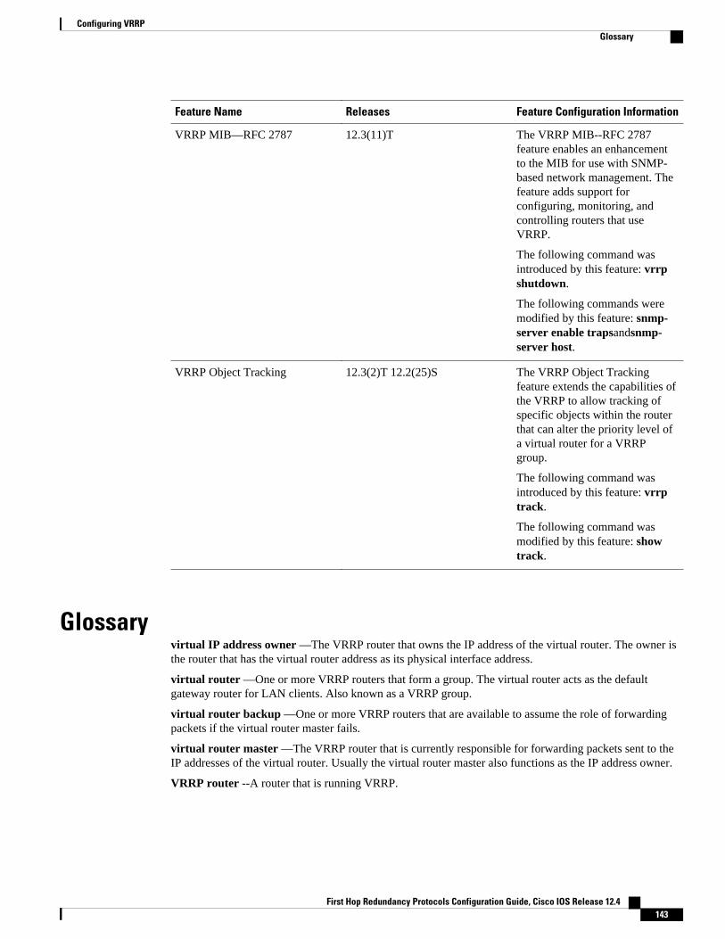
Feature Name Releases Feature Configuration Information
VRRP MIB—RFC 2787 12.3(11)T The VRRP MIB--RFC 2787feature enables an enhancementto the MIB for use with SNMP-based network management. Thefeature adds support forconfiguring, monitoring, andcontrolling routers that useVRRP.
The following command wasintroduced by this feature: vrrpshutdown.
The following commands weremodified by this feature: snmp-server enable trapsandsnmp-server host.
VRRP Object Tracking 12.3(2)T 12.2(25)S The VRRP Object Trackingfeature extends the capabilities ofthe VRRP to allow tracking ofspecific objects within the routerthat can alter the priority level ofa virtual router for a VRRPgroup.
The following command wasintroduced by this feature: vrrptrack.
The following command wasmodified by this feature: showtrack.
Glossaryvirtual IP address owner —The VRRP router that owns the IP address of the virtual router. The owner isthe router that has the virtual router address as its physical interface address.
virtual router —One or more VRRP routers that form a group. The virtual router acts as the defaultgateway router for LAN clients. Also known as a VRRP group.
virtual router backup —One or more VRRP routers that are available to assume the role of forwardingpackets if the virtual router master fails.
virtual router master —The VRRP router that is currently responsible for forwarding packets sent to theIP addresses of the virtual router. Usually the virtual router master also functions as the IP address owner.
VRRP router --A router that is running VRRP.
Configuring VRRPGlossary
First Hop Redundancy Protocols Configuration Guide, Cisco IOS Release 12.4 143
Cisco and the Cisco logo are trademarks or registered trademarks of Cisco and/or its affiliates in the U.S.and other countries. To view a list of Cisco trademarks, go to this URL: www.cisco.com/go/trademarks.Third-party trademarks mentioned are the property of their respective owners. The use of the word partnerdoes not imply a partnership relationship between Cisco and any other company. (1110R)
Any Internet Protocol (IP) addresses and phone numbers used in this document are not intended to beactual addresses and phone numbers. Any examples, command display output, network topology diagrams,and other figures included in the document are shown for illustrative purposes only. Any use of actual IPaddresses or phone numbers in illustrative content is unintentional and coincidental.
Configuring VRRP
First Hop Redundancy Protocols Configuration Guide, Cisco IOS Release 12.4144