fire/smoke dampers fire/smoke dampers (3v, airfoil, parallel, opposed, ... dampers shall be handled...
TRANSCRIPT
35 All Metric dimensions ( ) are soft conversion. © Copyright E.H. Price Limited 2011. Imperial dimensions are converted to metric and rounded to the nearest millimetre.
Important General Notes:When UL is referred to in this document, it represents UL/ULC. This installation instruction applies to Combination Fire/Smoke Dampers (3V, Airfoil, Parallel, Opposed, Single, and Multi-blade types) mounted in the plane of an UL approved fire partition. Combination Fire /Smoke Dampers are approved for use in Static or Dynamic Systems. The dampers are designed for operation in the vertical or horizontal position with blades running horizontal. The dampers are to be installed square and free from twisting or racking. The dampers shall not be compressed or stretched into the opening.
Transportation and installation of the dampers shall be handled with the sleeve or frame. Do not lift the damper with the blades or actuator. Special care shall be given to the damper before installation and after to insure it is protected against dirt, weather, mortar and drywall dust, wall texture and paint. Any of these conditions could cause the damper not to operate correctly and void the warranty. Suitable access to inside duct is to be provided for inspection and replacement of parts such as heat response devices and actuators per NFPA 90A and local authority having jurisdiction. The need to seal the damper in the penetration is not required by Underwriters Laboratories. PRICE dampers have been tested and approved to be mounted without the use of sealants around the perimeter space between the damper and the penetration. As with all joints, contractor must seal duct-collar connections in the field after installation. PRICE Model numbers which are UL approved to utilize this installation are FSD-3V-211, FSD-3V-212, FSD-3V-231, FSD-3V-232, FSD-AF-211, FSD-AF-212, FSD-AF-231, FSD-AF-232.
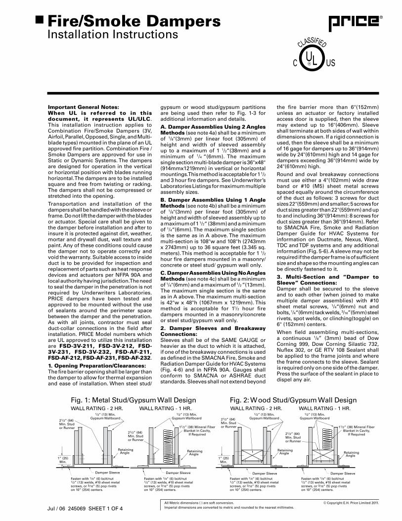
1. Opening Preparation/Clearances:The fire barrier opening shall be larger than the damper to allow for thermal expansion and ease of installation. When steel stud/
Fire/Smoke DampersInstallation Instructions
gypsum or wood stud/gypsum partitions are being used then refer to Fig. 1-3 for additional information and details.
A. Damper Assemblies Using 2 Angles Methods (see note 4a) shall be a minimum of 1/8"(3mm) per linear foot (305mm) of height and width of sleeved assembly up to a maximum of 1 1/2“(38mm) and a minimum of 1/4 “(6mm). The maximum single section multi-blade damper is 36"x48" (914mmx1219mm) in vertical or horizontal mountings. This method is acceptable for 1 1/2 and 3 hour fire dampers. See Underwriter’s Laboratories Listings for maximum multiple assembly sizes.
B. Damper Assemblies Using 1 Angle Methods (see note 4b) shall be a minimum of 1/8"(3mm) per linear foot (305mm) of height and width of sleeved assembly up to a maximum of 1 1/2“ (38mm) and a minimum of 1/4“(6mm). The maximum single section is the same as in A above. The maximum multi-section is 108"w and 108"h (2743mm x 2743mm) up to 36 square feet (3.345 sq. meters). This method is acceptable for 1 1/2 hour fire dampers mounted in a masonry/concrete or steel stud/ gypsum wall only.
C. Damper Assemblies Using No Angles Methods (see note 4c) shall be a minimum of 1/4"(6mm) and a maximum of 1/2 “(13mm). The maximum single section is the same as in A above. The maximum multi-section is 42"w x 48"h (1067mm x 1219mm). This method is acceptable for 11/2 hour fire dampers mounted in a masonry/concrete or steel stud/gypsum wall only.
2. Damper Sleeves and Breakaway Connections:Sleeves shall be of the SAME GAUGE or heavier as the duct to which it is attached, if one of the breakaway connections is used as defined in the SMACNA Fire, Smoke and Radiation Damper Guide for HVAC Systems (Fig. 4-6) and in NFPA 90A. Gauges shall conform to SMACNA or ASHRAE duct standards. Sleeves shall not extend beyond
the fire barrier more than 6"(152mm) unless an actuator or factory installed access door is supplied, then the sleeve may extend up to 16"(406mm). Sleeve shall terminate at both sides of wall within dimensions shown. If a rigid connection is used, then the sleeve shall be a minimum of 16 gage for dampers up to 36"(914mm) wide by 24"(610mm) high and 14 gage for dampers exceeding 36"(914mm) wide by 24"(610mm) high.
Round and oval breakaway connections must use either a 4"(102mm) wide draw band or #10 (M5) sheet metal screws spaced equally around the circumference of the duct as follows: 3 screws for duct sizes 22"(559mm) and smaller; 5 screws for duct sizes greater than 22"(559mm) and up to and including 36"(914mm): 8 screws for duct sizes greater than 36"(914mm). Refer to SMACNA Fire, Smoke and Radiation Damper Guide for HVAC Systems for information on Ductmate, Nexus, Ward, TDC and TDF systems and any additional information (Fig. 5-6). A sleeve may not be required if the damper frame is of sufficient size and shape so the mounting angles can be directly fastened to it.
3. Multi-Section and “Damper to Sleeve” Connections:Damper shall be secured to the sleeve and to each other (when joined to make multiple damper assemblies) with #10 sheet metal screws, 1/4“(6mm) nut and bolts, 1/4“(6mm) tack welds, 3/16”(5mm) steel rivets, spot welds, or clinching(toggle) on 6" (152mm) centers.
When field assembling multi-sections, a continuous 1/8” (3mm) bead of Dow Corning 999, Dow Corning Silastic 732, Nuflex 302, or GE RTV 108 Sealant shall be applied to the frame joints and where the frame connects to the sleeve. Sealant is required only on one side of the damper. Press the surface of the sealant in place to dispel any air.
Jul / 06 245069 SHEET 1 OF 4
36 All Metric dimensions ( ) are soft conversion. © Copyright E.H. Price Limited 2011. Imperial dimensions are converted to metric and rounded to the nearest millimetre.
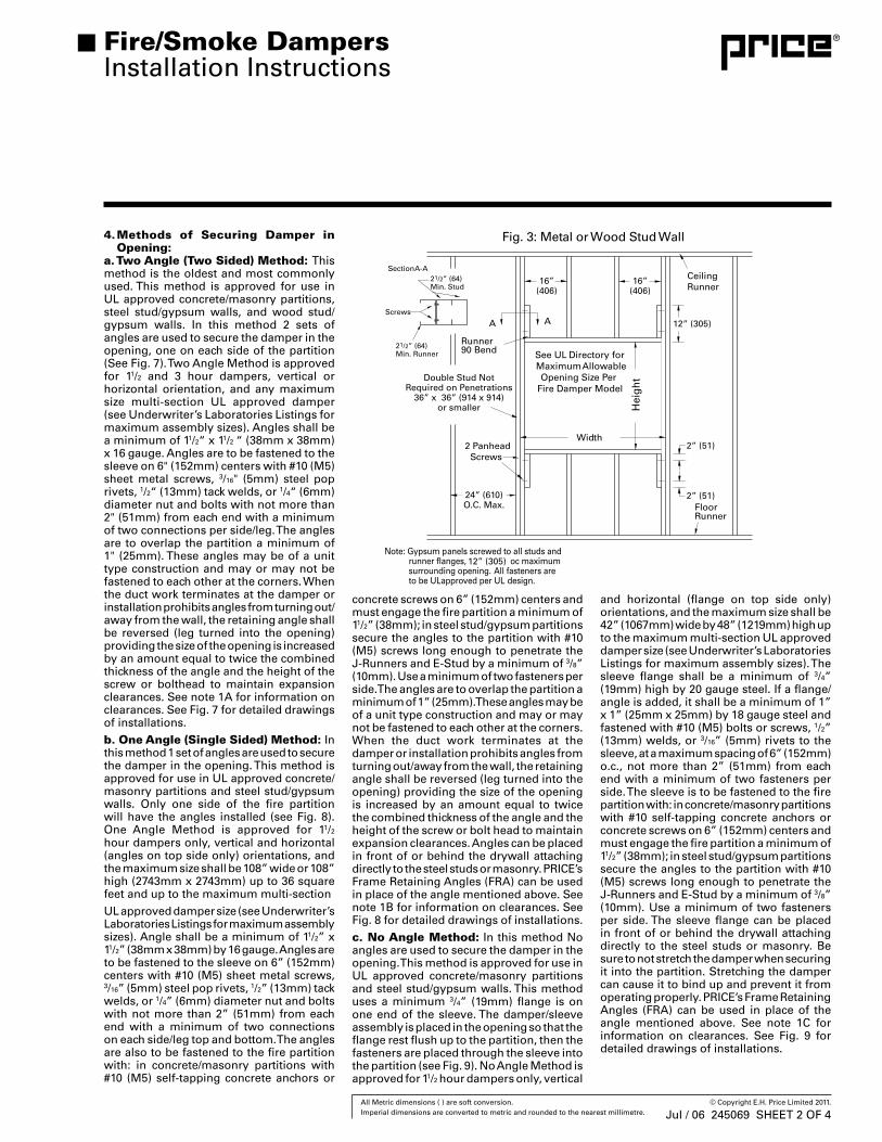
4. Methods of Securing Damper in Opening:
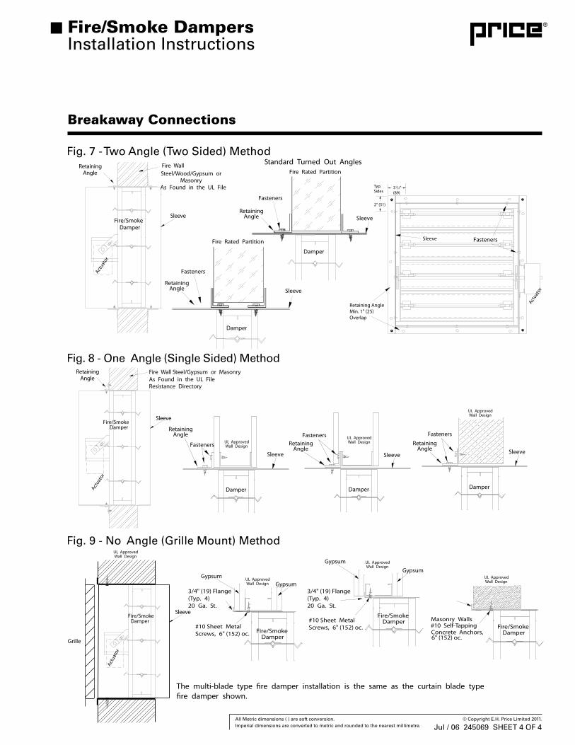
a. Two Angle (Two Sided) Method: This method is the oldest and most commonly used. This method is approved for use in UL approved concrete/masonry partitions, steel stud/gypsum walls, and wood stud/gypsum walls. In this method 2 sets of angles are used to secure the damper in the opening, one on each side of the partition (See Fig. 7). Two Angle Method is approved for 11/2 and 3 hour dampers, vertical or horizontal orientation, and any maximum size multi-section UL approved damper (see Underwriter’s Laboratories Listings for maximum assembly sizes). Angles shall be a minimum of 11/2“ x 11/2 “ (38mm x 38mm) x 16 gauge. Angles are to be fastened to the sleeve on 6" (152mm) centers with #10 (M5) sheet metal screws, 3/16" (5mm) steel pop rivets, 1/2“ (13mm) tack welds, or 1/4“ (6mm) diameter nut and bolts with not more than 2" (51mm) from each end with a minimum of two connections per side/leg. The angles are to overlap the partition a minimum of 1" (25mm). These angles may be of a unit type construction and may or may not be fastened to each other at the corners. When the duct work terminates at the damper or installation prohibits angles from turning out/away from the wall, the retaining angle shall be reversed (leg turned into the opening) providing the size of the opening is increased by an amount equal to twice the combined thickness of the angle and the height of the screw or bolthead to maintain expansion clearances. See note 1A for information on clearances. See Fig. 7 for detailed drawings of installations.b. One Angle (Single Sided) Method: In this method 1 set of angles are used to secure the damper in the opening. This method is approved for use in UL approved concrete/masonry partitions and steel stud/gypsum walls. Only one side of the fire partition will have the angles installed (see Fig. 8). One Angle Method is approved for 11/2
hour dampers only, vertical and horizontal (angles on top side only) orientations, and the maximum size shall be 108” wide or 108” high (2743mm x 2743mm) up to 36 square feet and up to the maximum multi-sectionUL approved damper size (see Underwriter’s Laboratories Listings for maximum assembly sizes). Angle shall be a minimum of 11/2” x 11/2” (38mm x 38mm) by 16 gauge. Angles are to be fastened to the sleeve on 6” (152mm) centers with #10 (M5) sheet metal screws, 3/16” (5mm) steel pop rivets, 1/2” (13mm) tack welds, or 1/4” (6mm) diameter nut and bolts with not more than 2” (51mm) from each end with a minimum of two connections on each side/leg top and bottom. The angles are also to be fastened to the fire partition with: in concrete/masonry partitions with #10 (M5) self-tapping concrete anchors or
concrete screws on 6” (152mm) centers and must engage the fire partition a minimum of 11/2” (38mm); in steel stud/gypsum partitions secure the angles to the partition with #10 (M5) screws long enough to penetrate the J-Runners and E-Stud by a minimum of 3/8” (10mm). Use a minimum of two fasteners per side. The angles are to overlap the partition a minimum of 1” (25mm). These angles may be of a unit type construction and may or may not be fastened to each other at the corners. When the duct work terminates at the damper or installation prohibits angles from turning out/away from the wall, the retaining angle shall be reversed (leg turned into the opening) providing the size of the opening is increased by an amount equal to twice the combined thickness of the angle and the height of the screw or bolt head to maintain expansion clearances. Angles can be placed in front of or behind the drywall attaching directly to the steel studs or masonry. PRICE’s Frame Retaining Angles (FRA) can be used in place of the angle mentioned above. See note 1B for information on clearances. See Fig. 8 for detailed drawings of installations.c. No Angle Method: In this method No angles are used to secure the damper in the opening. This method is approved for use in UL approved concrete/masonry partitions and steel stud/gypsum walls. This method uses a minimum 3/4” (19mm) flange is on one end of the sleeve. The damper/sleeve assembly is placed in the opening so that the flange rest flush up to the partition, then the fasteners are placed through the sleeve into the partition (see Fig. 9). No Angle Method is approved for 11/2 hour dampers only, vertical
and horizontal (flange on top side only) orientations, and the maximum size shall be 42” (1067mm) wide by 48” (1219mm) high up to the maximum multi-section UL approved damper size (see Underwriter’s Laboratories Listings for maximum assembly sizes). The sleeve flange shall be a minimum of 3/4” (19mm) high by 20 gauge steel. If a flange/angle is added, it shall be a minimum of 1” x 1” (25mm x 25mm) by 18 gauge steel and fastened with #10 (M5) bolts or screws, 1/2” (13mm) welds, or 3/16” (5mm) rivets to the sleeve, at a maximum spacing of 6” (152mm) o.c., not more than 2” (51mm) from each end with a minimum of two fasteners per side. The sleeve is to be fastened to the fire partition with: in concrete/masonry partitions with #10 self-tapping concrete anchors or concrete screws on 6” (152mm) centers and must engage the fire partition a minimum of 11/2” (38mm); in steel stud/gypsum partitions secure the angles to the partition with #10 (M5) screws long enough to penetrate the J-Runners and E-Stud by a minimum of 3/8” (10mm). Use a minimum of two fasteners per side. The sleeve flange can be placed in front of or behind the drywall attaching directly to the steel studs or masonry. Be sure to not stretch the damper when securing it into the partition. Stretching the damper can cause it to bind up and prevent it from operating properly. PRICE’s Frame Retaining Angles (FRA) can be used in place of the angle mentioned above. See note 1C for information on clearances. See Fig. 9 for detailed drawings of installations.
Fire/Smoke DampersInstallation Instructions
Jul / 06 245069 SHEET 2 OF 4
37 All Metric dimensions ( ) are soft conversion. © Copyright E.H. Price Limited 2011. Imperial dimensions are converted to metric and rounded to the nearest millimetre.
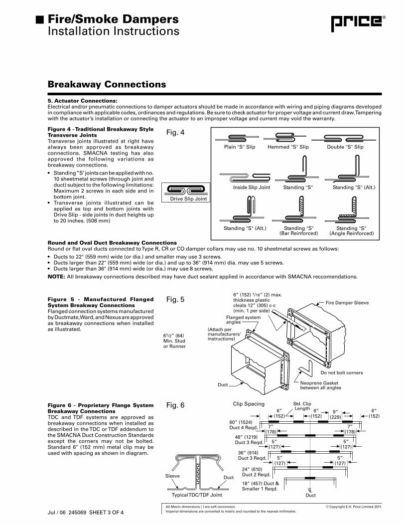
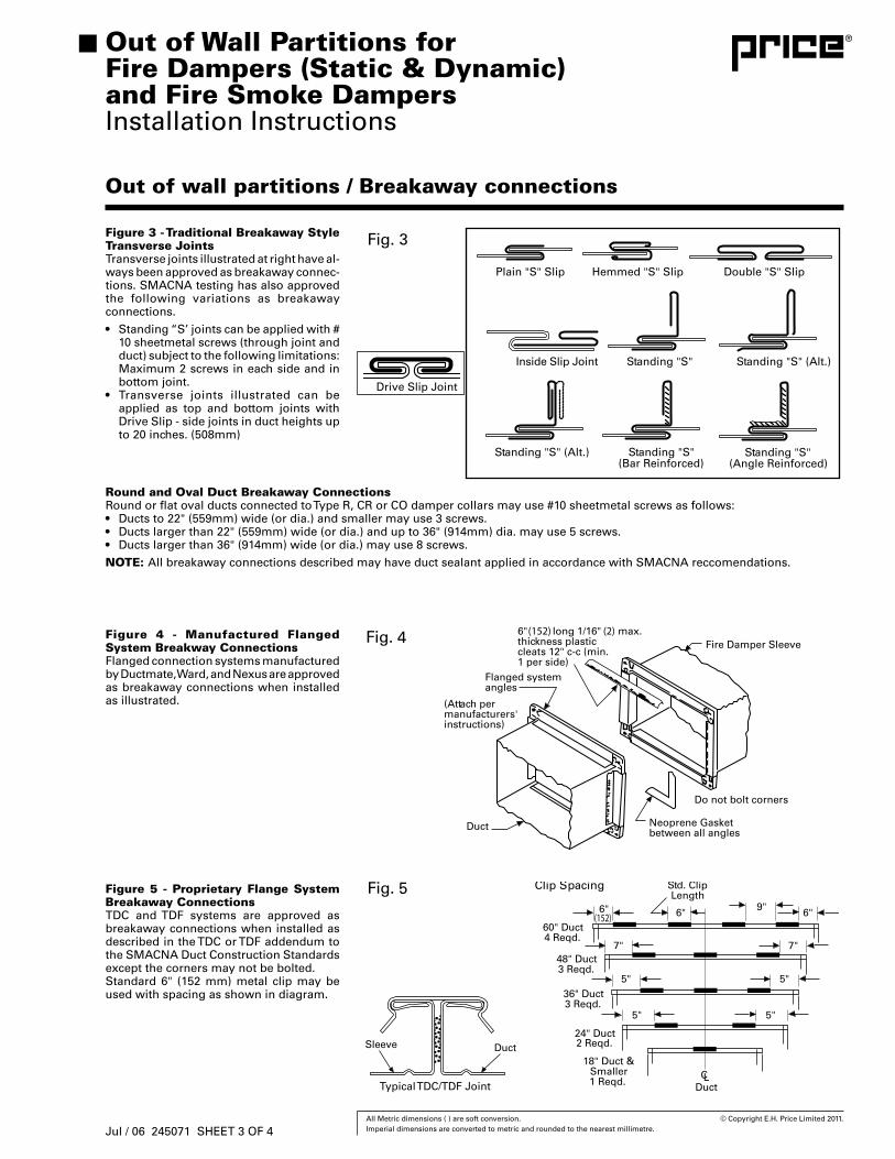
Figure 4 - Traditional Breakaway Style Transverse JointsTransverse joints illustrated at right have always been approved as breakaway connections. SMACNA testing has also approved the following variations as breakaway connections.
• Standing “S’ joints can be applied with no. 10 sheetmetal screws (through joint and duct) subject to the following limitations: Maximum 2 screws in each side and in bottom joint.
• Transverse joints illustrated can be applied as top and bottom joints with Drive Slip - side joints in duct heights up to 20 inches. (508 mm)
Breakaway Connections
Round and Oval Duct Breakaway ConnectionsRound or flat oval ducts connected to Type R, CR or CO damper collars may use no. 10 sheetmetal screws as follows:
• Ducts to 22" (559 mm) wide (or dia.) and smaller may use 3 screws.• Ducts larger than 22" (559 mm) wide (or dia.) and up to 36" (914 mm) dia. may use 5 screws.• Ducts larger than 36" (914 mm) wide (or dia.) may use 8 screws.
NOTE: All breakaway connections described may have duct sealant applied in accordance with SMACNA reccomendations.
Figure 5 - Manufactured Flanged System Breakway ConnectionsFlanged connection systems manufactured by Ductmate, Ward, and Nexus are approved as breakaway connections when installed as illustrated.
Figure 6 - Proprietary Flange System Breakaway ConnectionsTDC and TDF systems are approved as breakaway connections when installed as described in the TDC or TDF addendum to the SMACNA Duct Construction Standards except the corners may not be bolted. Standard 6" (152 mm) metal clip may be used with spacing as shown in diagram.
Fire/Smoke DampersInstallation Instructions
5. Actuator Connections:Electrical and/or pneumatic connections to damper actuators should be made in accordance with wiring and piping diagrams developed in compliance with applicable codes, ordinances and regulations. Be sure to check actuator for proper voltage and current draw. Tampering with the actuator’s installation or connecting the actuator to an improper voltage and current may void the warranty.
Jul / 06 245069 SHEET 3 OF 4
38 All Metric dimensions ( ) are soft conversion. © Copyright E.H. Price Limited 2011. Imperial dimensions are converted to metric and rounded to the nearest millimetre.
Breakaway Connections
Fire/Smoke DampersInstallation Instructions
Jul / 06 245069 SHEET 4 OF 4
39 All Metric dimensions ( ) are soft conversion. © Copyright E.H. Price Limited 2011. Imperial dimensions are converted to metric and rounded to the nearest millimetre.
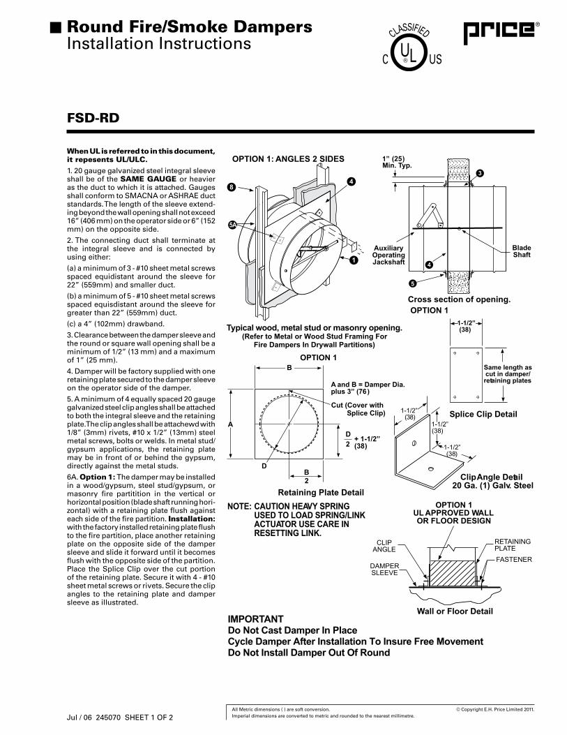
FSD-RD
When UL is referred to in this document, it repesents UL/ULC.1. 20 gauge galvanized steel integral sleeve shall be of the SAME GAUGE or heavier as the duct to which it is attached. Gauges shall conform to SMACNA or ASHRAE duct standards. The length of the sleeve extend-ing beyond the wall opening shall not exceed 16” (406 mm) on the operator side or 6” (152 mm) on the opposite side.
2. The connecting duct shall terminate at the integral sleeve and is connected by using either:
(a) a minimum of 3 - #10 sheet metal screws spaced equidistant around the sleeve for 22” (559mm) and smaller duct.
(b) a minimum of 5 - #10 sheet metal screws spaced equisdistant around the sleeve for greater than 22” (559mm) duct.
(c) a 4” (102mm) drawband.
3. Clearance between the damper sleeve and the round or square wall opening shall be a minimum of 1/2” (13 mm) and a maximum of 1” (25 mm).
4. Damper will be factory supplied with one retaining plate secured to the damper sleeve on the operator side of the damper.
5. A minimum of 4 equally spaced 20 gauge galvanized steel clip angles shall be attached to both the integral sleeve and the retaining plate. The clip angles shall be attachewd with 1/8” (3mm) rivets, #10 x 1/2” (13mm) steel metal screws, bolts or welds. In metal stud/gypsum applications, the retaining plate may be in front of or behind the gypsum, directly against the metal studs.
6A. Option 1: The damper may be installed in a wood/gypsum, steel stud/gypsum, or masonry fire partitition in the vertical or horizontal position (blade shaft running hori-zontal) with a retaining plate flush against each side of the fire partition. Installation: with the factory installed retaining plate flush to the fire partition, place another retaining plate on the opposite side of the damper sleeve and slide it forward until it becomes flush with the opposite side of the partition. Place the Splice Clip over the cut portion of the retaining plate. Secure it with 4 - #10 sheet metal screws or rivets. Secure the clip angles to the retaining plate and damper sleeve as illustrated.
Round Fire/Smoke DampersInstallation Instructions
Jul / 06 245070 SHEET 1 OF 2
40 All Metric dimensions ( ) are soft conversion. © Copyright E.H. Price Limited 2011. Imperial dimensions are converted to metric and rounded to the nearest millimetre.
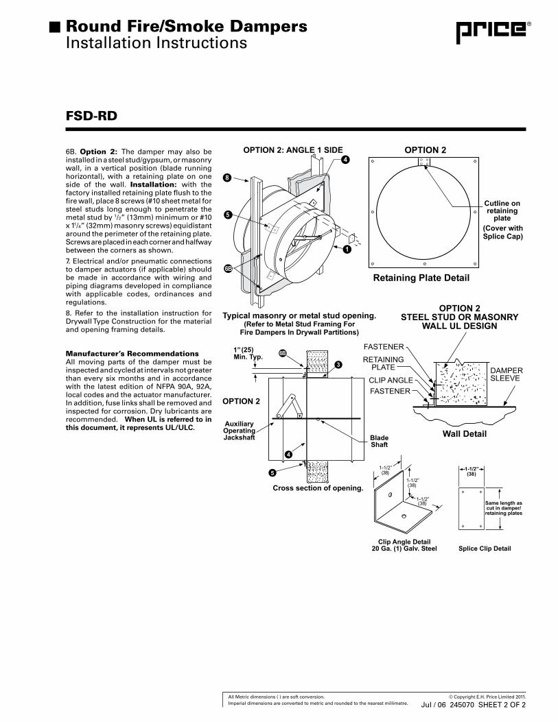
6B. Option 2: The damper may also be installed in a steel stud/gypsum, or masonry wall, in a vertical position (blade running horizontal), with a retaining plate on one side of the wall. Installation: with the factory installed retaining plate flush to the fire wall, place 8 screws (#10 sheet metal for steel studs long enough to penetrate the metal stud by 1/2” (13mm) minimum or #10 x 11/4” (32mm) masonry screws) equidistant around the perimeter of the retaining plate. Screws are placed in each corner and halfway between the corners as shown.
7. Electrical and/or pneumatic connections to damper actuators (if applicable) should be made in accordance with wiring and piping diagrams developed in compliance with applicable codes, ordinances and regulations.
8. Refer to the installation instruction for Drywall Type Construction for the material and opening framing details.
Manufacturer’s RecommendationsAll moving parts of the damper must be inspected and cycled at intervals not greater than every six months and in accordance with the latest edition of NFPA 90A, 92A, local codes and the actuator manufacturer. In addition, fuse links shall be removed and inspected for corrosion. Dry lubricants are recommended. When UL is referred to in this document, it represents UL/ULC.
FSD-RD
Round Fire/Smoke DampersInstallation Instructions
Jul / 06 245070 SHEET 2 OF 2
41 All Metric dimensions ( ) are soft conversion. © Copyright E.H. Price Limited 2011. Imperial dimensions are converted to metric and rounded to the nearest millimetre.
Out of Wall Partitions for Fire Dampers (Static & Dynamic)and Fire Smoke DampersInstallation Instructions
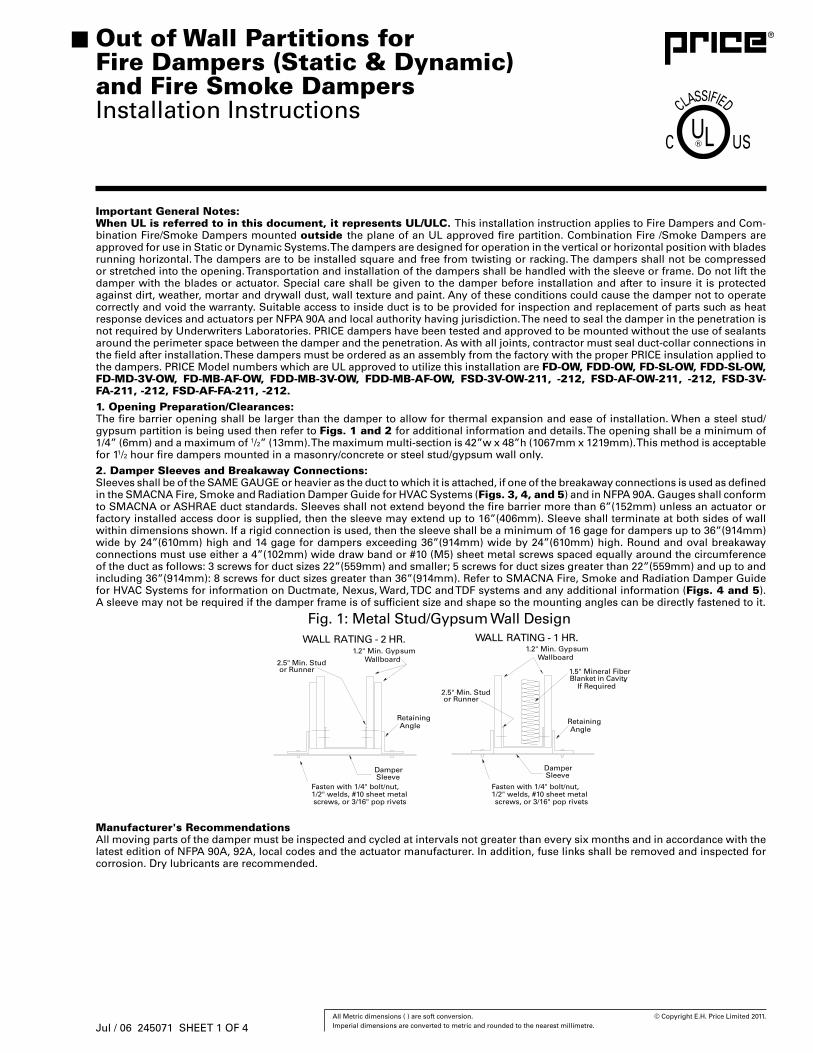
Important General Notes:When UL is referred to in this document, it represents UL/ULC. This installation instruction applies to Fire Dampers and Com-bination Fire/Smoke Dampers mounted outside the plane of an UL approved fire partition. Combination Fire /Smoke Dampers are approved for use in Static or Dynamic Systems. The dampers are designed for operation in the vertical or horizontal position with blades running horizontal. The dampers are to be installed square and free from twisting or racking. The dampers shall not be compressed or stretched into the opening. Transportation and installation of the dampers shall be handled with the sleeve or frame. Do not lift the damper with the blades or actuator. Special care shall be given to the damper before installation and after to insure it is protected against dirt, weather, mortar and drywall dust, wall texture and paint. Any of these conditions could cause the damper not to operate correctly and void the warranty. Suitable access to inside duct is to be provided for inspection and replacement of parts such as heat response devices and actuators per NFPA 90A and local authority having jurisdiction. The need to seal the damper in the penetration is not required by Underwriters Laboratories. PRICE dampers have been tested and approved to be mounted without the use of sealants around the perimeter space between the damper and the penetration. As with all joints, contractor must seal duct-collar connections in the field after installation. These dampers must be ordered as an assembly from the factory with the proper PRICE insulation applied to the dampers. PRICE Model numbers which are UL approved to utilize this installation are FD-OW, FDD-OW, FD-SL-OW, FDD-SL-OW, FD-MD-3V-OW, FD-MB-AF-OW, FDD-MB-3V-OW, FDD-MB-AF-OW, FSD-3V-OW-211, -212, FSD-AF-OW-211, -212, FSD-3V-FA-211, -212, FSD-AF-FA-211, -212.1. Opening Preparation/Clearances:The fire barrier opening shall be larger than the damper to allow for thermal expansion and ease of installation. When a steel stud/gypsum partition is being used then refer to Figs. 1 and 2 for additional information and details. The opening shall be a minimum of 1/4” (6mm) and a maximum of 1/2” (13mm). The maximum multi-section is 42”w x 48”h (1067mm x 1219mm). This method is acceptable for 11/2 hour fire dampers mounted in a masonry/concrete or steel stud/gypsum wall only.
2. Damper Sleeves and Breakaway Connections:Sleeves shall be of the SAME GAUGE or heavier as the duct to which it is attached, if one of the breakaway connections is used as defined in the SMACNA Fire, Smoke and Radiation Damper Guide for HVAC Systems (Figs. 3, 4, and 5) and in NFPA 90A. Gauges shall conform to SMACNA or ASHRAE duct standards. Sleeves shall not extend beyond the fire barrier more than 6”(152mm) unless an actuator or factory installed access door is supplied, then the sleeve may extend up to 16”(406mm). Sleeve shall terminate at both sides of wall within dimensions shown. If a rigid connection is used, then the sleeve shall be a minimum of 16 gage for dampers up to 36”(914mm) wide by 24”(610mm) high and 14 gage for dampers exceeding 36”(914mm) wide by 24”(610mm) high. Round and oval breakaway connections must use either a 4”(102mm) wide draw band or #10 (M5) sheet metal screws spaced equally around the circumference of the duct as follows: 3 screws for duct sizes 22”(559mm) and smaller; 5 screws for duct sizes greater than 22”(559mm) and up to and including 36”(914mm): 8 screws for duct sizes greater than 36”(914mm). Refer to SMACNA Fire, Smoke and Radiation Damper Guide for HVAC Systems for information on Ductmate, Nexus, Ward, TDC and TDF systems and any additional information (Figs. 4 and 5). A sleeve may not be required if the damper frame is of sufficient size and shape so the mounting angles can be directly fastened to it.
Manufacturer's RecommendationsAll moving parts of the damper must be inspected and cycled at intervals not greater than every six months and in accordance with the latest edition of NFPA 90A, 92A, local codes and the actuator manufacturer. In addition, fuse links shall be removed and inspected for corrosion. Dry lubricants are recommended.
Jul / 06 245071 SHEET 1 OF 4
42 All Metric dimensions ( ) are soft conversion. © Copyright E.H. Price Limited 2011. Imperial dimensions are converted to metric and rounded to the nearest millimetre.
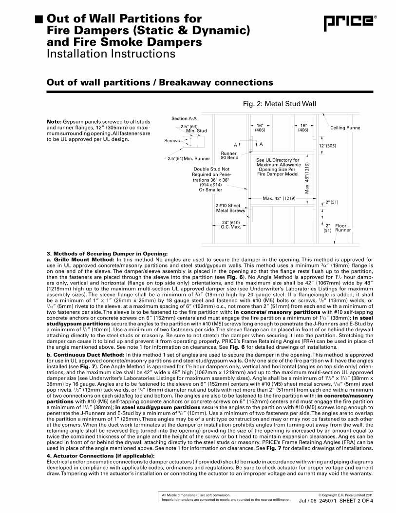
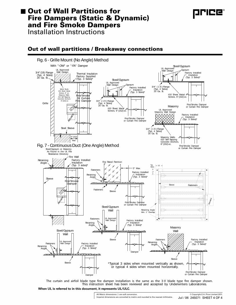
3. Methods of Securing Damper in Opening:a. Grille Mount Method: In this method No angles are used to secure the damper in the opening. This method is approved for use in UL approved concrete/masonry partitions and steel stud/gypsum walls. This method uses a minimum 3/4” (19mm) flange is on one end of the sleeve. The damper/sleeve assembly is placed in the opening so that the flange rests flush up to the partition, then the fasteners are placed through the sleeve into the partition (see Fig. 6). No Angle Method is approved for 11/2 hour damp-ers only, vertical and horizontal (flange on top side only) orientations, and the maximum size shall be 42” (1067mm) wide by 48” (1219mm) high up to the maximum multi-section UL approved damper size (see Underwriter’s Laboratories Listings for maximum assembly sizes). The sleeve flange shall be a minimum of 3/4” (19mm) high by 20 gauge steel. If a flange/angle is added, it shall be a minimum of 1” x 1” (25mm x 25mm) by 18 gauge steel and fastened with #10 (M5) bolts or screws, 1/2” (13mm) welds, or3/16” (5mm) rivets to the sleeve, at a maximum spacing of 6” (152mm) o.c., not more than 2” (51mm) from each end with a minimum of two fasteners per side. The sleeve is to be fastened to the fire partition with: in concrete/ masonry partitions with #10 self-tapping concrete anchors or concrete screws on 6” (152mm) centers and must engage the fire partition a minimum of 11/2” (38mm); in steel stud/gypsum partitions secure the angles to the partition with #10 (M5) screws long enough to penetrate the J-Runners and E-Stud by a minimum of 3/8” (10mm). Use a minimum of two fasteners per side. The sleeve flange can be placed in front of or behind the drywall attaching directly to the steel studs or masonry. Be sure to not stretch the damper when securing it into the partition. Stretching the damper can cause it to bind up and prevent it from operating properly. PRICE’s Frame Retaining Angles (FRA) can be used in place of the angle mentioned above. See note 1 for information on clearances. See Fig. 6 for detailed drawings of installations.
b. Continuous Duct Method: In this method 1 set of angles are used to secure the damper in the opening. This method is approved for use in UL approved concrete/masonry partitions and steel stud/gypsum walls. Only one side of the fire partition will have the angles installed (see Fig. 7). One Angle Method is approved for 11/2 hour dampers only, vertical and horizontal (angles on top side only) orien-tations, and the maximum size shall be 42” wide x 48” high (1067mm x 1219mm) and up to the maximum multi-section UL approved damper size (see Underwriter’s Laboratories Listings for maximum assembly sizes). Angle shall be a minimum of 11/2” x 11/2” (38mm x 38mm) by 16 gauge. Angles are to be fastened to the sleeve on 6” (152mm) centers with #10 (M5) sheet metal screws, 3/16” (5mm) steel pop rivets, 1/2” (13mm) tack welds, or 1/4” (6mm) diameter nut and bolts with not more than 2” (51mm) from each end with a minimum of two connections on each side/leg top and bottom. The angles are also to be fastened to the fire partition with: in concrete/masonry partitions with #10 (M5) self-tapping concrete anchors or concrete screws on 6” (152mm) centers and must engage the fire partition a minimum of 11/2” (38mm); in steel stud/gypsum partitions secure the angles to the partition with #10 (M5) screws long enough to penetrate the J-Runners and E-Stud by a minimum of 3/8” (10mm). Use a minimum of two fasteners per side. The angles are to overlap the partition a minimum of 1” (25mm). These angles may be of a unit type construction and may or may not be fastened to each other at the corners. When the duct work terminates at the damper or installation prohibits angles from turning out away from the wall, the retaining angle shall be reversed (leg turned into the opening) providing the size of the opening is increased by an amount equal to twice the combined thickness of the angle and the height of the screw or bolt head to maintain expansion clearances. Angles can be placed in front of or behind the drywall attaching directly to the steel studs or masonry. PRICE’s Frame Retaining Angles (FRA) can be used in place of the angle mentioned above. See note 1 for information on clearances. See Fig. 7 for detailed drawings of installations.
4. Actuator Connections (if applicable):Electrical and/or pneumatic connections to damper actuators (if provided) should be made in accordance with wiring and piping diagrams developed in compliance with applicable codes, ordinances and regulations. Be sure to check actuator for proper voltage and current draw. Tampering with the actuator’s installation or connecting the actuator to an improper voltage and current may void the warranty.
Note: Gypsum panels screwed to all studs and runner flanges, 12” (305mm) oc maxi-mum surrounding opening. All fasteners are to be UL approved per UL design.
Out of wall partitions / Breakaway connections
Out of Wall Partitions for Fire Dampers (Static & Dynamic)and Fire Smoke DampersInstallation Instructions
Jul / 06 245071 SHEET 2 OF 4
43 All Metric dimensions ( ) are soft conversion. © Copyright E.H. Price Limited 2011. Imperial dimensions are converted to metric and rounded to the nearest millimetre.
Out of wall partitions / Breakaway connections
(152)
(152)
(2)
Out of Wall Partitions for Fire Dampers (Static & Dynamic)and Fire Smoke DampersInstallation Instructions
Figure 3 - Traditional Breakaway Style Transverse JointsTransverse joints illustrated at right have al-ways been approved as breakaway connec-tions. SMACNA testing has also approved the following variations as breakaway connections.
• Standing “S’ joints can be applied with # 10 sheetmetal screws (through joint and duct) subject to the following limitations: Maximum 2 screws in each side and in bottom joint.
• Transverse joints illustrated can be applied as top and bottom joints with Drive Slip - side joints in duct heights up to 20 inches. (508mm)
Round and Oval Duct Breakaway ConnectionsRound or flat oval ducts connected to Type R, CR or CO damper collars may use #10 sheetmetal screws as follows:• Ducts to 22" (559mm) wide (or dia.) and smaller may use 3 screws.• Ducts larger than 22" (559mm) wide (or dia.) and up to 36" (914mm) dia. may use 5 screws.• Ducts larger than 36" (914mm) wide (or dia.) may use 8 screws.
NOTE: All breakaway connections described may have duct sealant applied in accordance with SMACNA reccomendations.
Figure 4 - Manufactured Flanged System Breakway ConnectionsFlanged connection systems manufactured by Ductmate, Ward, and Nexus are approved as breakaway connections when installed as illustrated.
Figure 5 - Proprietary Flange System Breakaway ConnectionsTDC and TDF systems are approved as breakaway connections when installed as described in the TDC or TDF addendum to the SMACNA Duct Construction Standards except the corners may not be bolted.Standard 6" (152 mm) metal clip may be used with spacing as shown in diagram.
(152)
(152)
(2)(152)
(152)
(2)
Jul / 06 245071 SHEET 3 OF 4
44 All Metric dimensions ( ) are soft conversion. © Copyright E.H. Price Limited 2011. Imperial dimensions are converted to metric and rounded to the nearest millimetre.
Grille
3/4" (19) Flange(Typ. 4 Sides)20 Ga. St.
Thermal InsulationFactory Supplied(Typ. 3 Sides)*
Fire/SmokeOr Curtain
Fire Damper
Steel Sleeve
UL ApprovedWall Design
With "-OW" or "-FA" Damper
Metal Studs#10 Sheet MetalScrews, 8" oc.Masonry Walls
#10 Self-TappingConcrete Anchors
oc
Actu
ator
6" (152)
Max
Retaining Angle
Steel/Gypsum or MasonryAs Found in the UL File
Resistance Directory
Fire/SmokeDamper
Sleeve
Actu
ator
Factory InstalledInsulation(Typ. 3 sides)*
Fire Wall
3/4" ( 1 9 ) Flange(Typ. 4 Sides)20 Ga. St.
#10 Sheet MetalScrews, 6" (152)
6" (152)
oc.
Fire/Smoke Damperor Curtain Fire Damper
Factory InstalledInsulation
(Typ. 3 Sides)*
GypsumUL ApprovedWall Design
Steel/Gypsum
Masonry Walls#10 Self-TappingConcrete Anchors,
Fire/Smoke Damperor Curtain Fire Damper
Factory InstalledInsulation
(Typ. 3 Sides)*
UL ApprovedMasonry Wall Design
MasonryFire/Smoke Damper
or Curtain Fire Damper
Factory InstalledInsulation
(Typ. 3 Sides)*
GypsumUL ApprovedWall Design
Steel/Gypsum
3.5
2"
Retaining AngleMin. 1" Overlap
Sleeve
Typ.Sides
Fasteners
Actu
ator
Fasteners
Fire/Smoke Damperor Curtain Fire Damper
Factory InstalledInsulation
(Typ. 3 Sides)*
Sleeve
Fasteners
Retaining Angle
Fire Rated Partition
5" Max.
Factory InstalledInsulation
(Typ. 3 Sides)*
Sleeve
Fasteners
Retaining Angle
UL ApprovedWall Design
Damper
Steel/GypsumWall
Factory InstalledInsulation
(Typ. 3 Sides)*
Sleeve
FastenersRetaining Angle
UL ApprovedWall Design
Damper
Steel/GypsumWall
Factory InstalledInsulation
(Typ. 3 Sides)*
Sleeve
FastenersRetaining Angle
MasonryWall
Fire/Smoke Damperor Curtain Fire Damper
This instruction sheet has been reviewed and accepted by Underwriters Laboratories.
*Typical 3 sides when mounted vertically as shown, or typical 4 sides when mounted horizontally.
Fig. 6 - Grille Mount (No Angle) Method
Fig. 7 - Continuous Duct (One Angle) Method
#10 Sheet MetalScrews, 6" (152) oc.
6" (152) oc.
3/4" ( 1 9 ) Flange(Typ. 4 Sides)20 Ga. St.
3/4" ( 1 9 ) Flange(Typ. 4 Sides)20 Ga. St.
Out of wall partitions / Breakaway connections
Out of Wall Partitions for Fire Dampers (Static & Dynamic)and Fire Smoke DampersInstallation Instructions
When UL is referred to in this document, it represents UL/ULC.
Jul / 06 245071 SHEET 4 OF 4

46 All Metric dimensions ( ) are soft conversion. © Copyright E.H. Price Limited 2011. Imperial dimensions are converted to metric and rounded to the nearest millimetre.
Horz. to Vert.Mullion Cap
C-C (Typical)
These installation instructions apply to the fabrication and construction of generic sup-port mullions. Support mullions are neces-sary whenever fire dampers are installed into an opening that is larger than the largest UL rated size for that damper. The mullions allow construction of a fire barrier that is larger than the maximum available size.
The opening must not exceed 120" (3048mm) high, but can be any width provided a verti-cal support mullion is used a maximum of every 120" (3048mm).
To properly use support mullions they must be fabricated and installed according to these instructions.
This generic support mullion is permitted by UL to only be used in static systems. A static system is one in which the fan shuts down in the event of a fire or smoke alarm.
ApplicationGeneric steel mullions can be used to sepa-rate vertically mounted galvanized steel fire dampers in wall openings larger
than the UL permitted multiple damper assembly size. Mullions can either be used vertically, horizontally or both to split up a vertical wall opening requiring use of a damper having a 11/2 hour fire resistance rating. Maximum mullion span is 120" (3048mm) plus expansion allowance when used either horizontally or vertically.
Sleeves are to be around each damper as-sembly. Mullions are not intended to be in the airstream, (i.e. exposed to flow) or to be a part of the ductwork.
Wall OpeningSteel mullions are intended for use in a concrete block or solid concrete wall. Hollow concrete blocks are to be filled with concrete (minimum 3500 psi) to permit proper mul-lion anchoring.
Wall thickness is to be 7" (178mm) minimum, 12" (305mm) maximum.
Support Mullions for Fire Dampers and Fire Smoke DampersFabrication and Installation Instructions
Manufacturer's RecommendationsAll moving parts of the damper must be inspected and cycled at intervals not greater than every six months and in accordance with the latest edition of NFPA 90A, 92A, local codes and the actuator manufacturer. In addition, fuse links shall be removed and inspected for corrosion. Dry lubricants are recommended. When UL is referred to in this document, it represents UL/ULC.
Jul / 06 245073 SHEET 1 OF 4

47 All Metric dimensions ( ) are soft conversion. © Copyright E.H. Price Limited 2011. Imperial dimensions are converted to metric and rounded to the nearest millimetre.
12” (305) 11-1/2” (292) 3-1/4” (83)24” (610) 23-1/2” (597) 3-3/8” (86)36” (914) 33-3/8” (848) 3-1/2” (8948“ (1219) 47-1/4” (1200) 3-5/8” (92)60“ (1524) 59-1/8” (1502) 3-3/4 ” (95)72“ (1829) 71” (1803) 3-7/8” (98)84“ (2134) 82-7/8” (2105) 4” (102)96“ (2438) 94-3/4” (2407) 4-1/8”(105) 108“ (2749) 106-3/4” (2711) 4-1/4” (108) 120“ (3048) 118-3/4” (3016) 4-3/8” (111)
(13)(6)
(51) (46) (51)
(83)
(83)
(19) (22)
(83)
(51) (51)
(5)
(89)
3/16” (5) blind rivet (std.) or 3/4” (19) long intermittent welds 12” (305) on center, 6” (152) max. from both ends, both sides of assembly
Support mullion assemblies consist of three basic parts: the wall mullion cap, the horizontal to vertical mullion cap and the mullion sections. Determine the number of each piece required to complete the installation.
Fabrication of Wall Mullion Caps (Fig. A-A)Wall mullion caps must be constructed from 12 ga. steel with a minimum yield strength of 42,000 psi.
1. Fabricate the formed section as shown below.2. Shear the cap end plate to required dimensions.
3. Weld the cap end plates to the formed section with 1/8" (3mm) fillet welds completely around the top edges of the formed section.
4. Drill and countersink 8 holes (4 on each side for 1/4" -20 flat head machine screws.
Fabrication of Mullion Sections (Fig. B-B)Mullions must be constructed from 16 ga. steel with a minimum yield strength of 42,000 psi.
Important: The “D” dimension shown has been calculated to include the necessary clearances required for thermal expansion in the mullions. The values can be found using the wall opening dimensions and tables on this page.
1. Form two identical pieces of mullion section as shown.
2. Connect the two mullion sections together. Use 3/16" (5mm) steel bind rivets or 3/4" (19mm) long stitch welds 12" (305mm) on center and a 6" (152m) maximum from both ends.
Important: Both sides of the mullion piece should be fastened using the method de-scribed above.
Support Mullions for Fire Dampers and Fire Smoke DampersFabrication and Installation Instructions
Jul / 06 245073 SHEET 2 OF 4
48 All Metric dimensions ( ) are soft conversion. © Copyright E.H. Price Limited 2011. Imperial dimensions are converted to metric and rounded to the nearest millimetre.
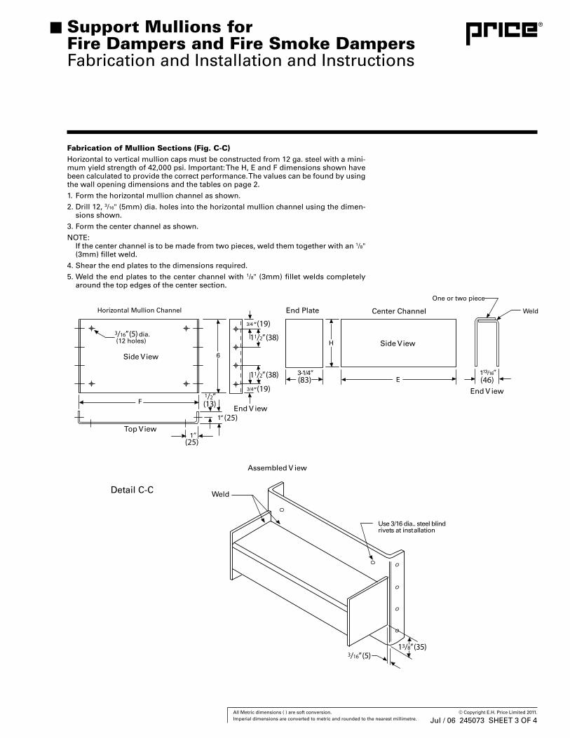
Fabrication of Mullion Sections (Fig. C-C)Horizontal to vertical mullion caps must be constructed from 12 ga. steel with a mini-mum yield strength of 42,000 psi. Important: The H, E and F dimensions shown have been calculated to provide the correct performance. The values can be found by using the wall opening dimensions and the tables on page 2.
1. Form the horizontal mullion channel as shown.
2. Drill 12, 3/16" (5mm) dia. holes into the horizontal mullion channel using the dimen-sions shown.
3. Form the center channel as shown.
NOTE: If the center channel is to be made from two pieces, weld them together with an 1/8"
(3mm) fillet weld.
4. Shear the end plates to the dimensions required.
5. Weld the end plates to the center channel with 1/8" (3mm) fillet welds completely around the top edges of the center section.
Support Mullions for Fire Dampers and Fire Smoke DampersFabrication and Installation and Instructions
Jul / 06 245073 SHEET 3 OF 4

49 All Metric dimensions ( ) are soft conversion. © Copyright E.H. Price Limited 2011. Imperial dimensions are converted to metric and rounded to the nearest millimetre.
Mullion InstallationBefore the fire dampers are installed into the wall the anchored into the wall. The fire dampers may then be installed into the mullion assembly.
To correctly attach the mullions to the wall follow these steps:
1. Anchor wall mullion caps to wall using 1/4"-20 x 5/16" long flat head steel bolts and 3/8" (10mm) diameter by 1" (25mm) long concrete expansion anchors (Hilti). If steel lintels are present, use two 1" (25mm) long welds on each side of mullion caps. Note: End caps must be inserted into the ends of the mullions before they are anchored to the wall.
2. Anchor horizontal mullion caps to vertical mullion caps with 3/16" (5mm) diameter steel blind rivets in 12 places. Note: Mullion caps must be inserted into the ends of the mullions before they are anchored to the vertical mullions or wall.
Fire Damper InstallationGalvanized steel fire dampers must be UL classified for 11/2 hour fire resistance. They must be installed in galvanized steel sleeves and be retained by minimum 11/2" x 11/2" 1" (38mm x 38mm), 16 ga. retaining angles on each side of the wall. Retaining angles must overlap mullions or wall by 1" minimum. Fasten to sleeve using 1/4" 1" (6mm) dia. bolts, 3/16" (5mm) steel rivets, welding, or #10 sheet metal screws. All must be attached 6" 1" (152mm) on centers, 2" (51mm) maximum from corners. Do not fasten retaining angles to the wall or mullions. Mullions must be free to float. Total expansion clearance between sleeve and wall/mullion of 1/8" per foot of wall opening or mullion span should be allowed. Maximum clearance is 11/4" 1" (32mm).
Support Mullions for Fire Dampers and Fire Smoke DampersFabrication and Installation Instructions
Manufacturer's RecommendationsAll moving parts of the damper must be inspected and cycled at intervals not greater than every six months and in accordance with the latest edition of NFPA 90A, 92A, local codes and the actuator manufacturer. In addition, fuse links shall be removed and inspected for corrosion. Dry lubricants are recommended.
Jul / 06 245073 SHEET 4 OF 4
50 All Metric dimensions ( ) are soft conversion. © Copyright E.H. Price Limited 2011. Imperial dimensions are converted to metric and rounded to the nearest millimetre.
Only if required by the authority having jurisdiction
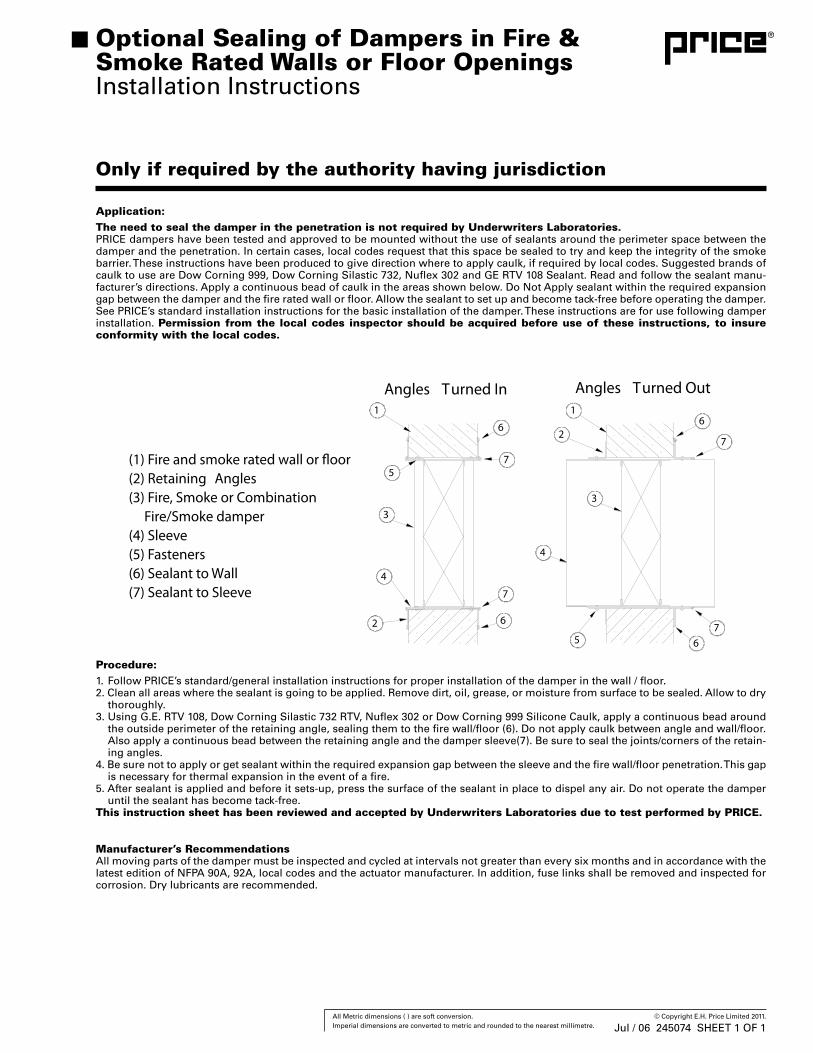
Application:The need to seal the damper in the penetration is not required by Underwriters Laboratories.PRICE dampers have been tested and approved to be mounted without the use of sealants around the perimeter space between the damper and the penetration. In certain cases, local codes request that this space be sealed to try and keep the integrity of the smoke barrier. These instructions have been produced to give direction where to apply caulk, if required by local codes. Suggested brands of caulk to use are Dow Corning 999, Dow Corning Silastic 732, Nuflex 302 and GE RTV 108 Sealant. Read and follow the sealant manu-facturer’s directions. Apply a continuous bead of caulk in the areas shown below. Do Not Apply sealant within the required expansion gap between the damper and the fire rated wall or floor. Allow the sealant to set up and become tack-free before operating the damper. See PRICE’s standard installation instructions for the basic installation of the damper. These instructions are for use following damper installation. Permission from the local codes inspector should be acquired before use of these instructions, to insure conformity with the local codes.
Manufacturer’s RecommendationsAll moving parts of the damper must be inspected and cycled at intervals not greater than every six months and in accordance with the latest edition of NFPA 90A, 92A, local codes and the actuator manufacturer. In addition, fuse links shall be removed and inspected for corrosion. Dry lubricants are recommended.
Procedure:1. Follow PRICE’s standard/general installation instructions for proper installation of the damper in the wall / floor.2. Clean all areas where the sealant is going to be applied. Remove dirt, oil, grease, or moisture from surface to be sealed. Allow to dry
thoroughly.3. Using G.E. RTV 108, Dow Corning Silastic 732 RTV, Nuflex 302 or Dow Corning 999 Silicone Caulk, apply a continuous bead around
the outside perimeter of the retaining angle, sealing them to the fire wall/floor (6). Do not apply caulk between angle and wall/floor. Also apply a continuous bead between the retaining angle and the damper sleeve(7). Be sure to seal the joints/corners of the retain-ing angles.
4. Be sure not to apply or get sealant within the required expansion gap between the sleeve and the fire wall/floor penetration. This gap is necessary for thermal expansion in the event of a fire.
5. After sealant is applied and before it sets-up, press the surface of the sealant in place to dispel any air. Do not operate the damper until the sealant has become tack-free.
This instruction sheet has been reviewed and accepted by Underwriters Laboratories due to test performed by PRICE.
Optional Sealing of Dampers in Fire & Smoke Rated Walls or Floor OpeningsInstallation Instructions
Jul / 06 245074 SHEET 1 OF 1
51 All Metric dimensions ( ) are soft conversion. © Copyright E.H. Price Limited 2011. Imperial dimensions are converted to metric and rounded to the nearest millimetre.
Accessories & Options
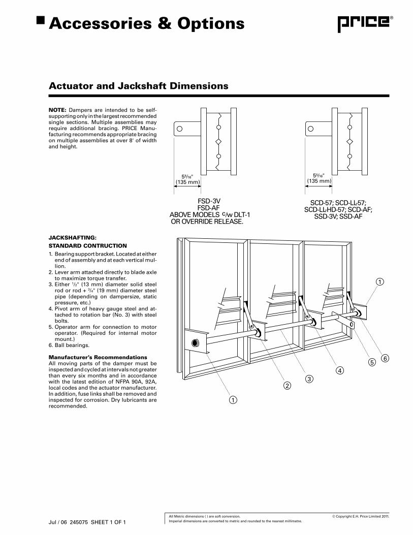
Actuator and Jackshaft Dimensions
NOTE: Dampers are intended to be self-supporting only in the largest recommended single sections. Multiple assemblies may require additional bracing. PRICE Manu-facturing recommends appropriate bracing on multiple assemblies at over 8' of width and height.
JACKSHAFTING:STANDARD CONTRUCTION1. Bearing support bracket. Located at either
end of assembly and at each vertical mul-lion.
2. Lever arm attached directly to blade axle to maximize torque transfer.
3. Either 1/2" (13 mm) diameter solid steel rod or rod + 3/4" (19 mm) diameter steel pipe (depending on dampersize, static pressure, etc.)
4. Pivot arm of heavy gauge steel and at-tached to rotation bar (No. 3) with steel bolts.
5. Operator arm for connection to motor operator. (Required for internal motor mount.)
6. Ball bearings.
Manufacturer’s RecommendationsAll moving parts of the damper must be inspected and cycled at intervals not greater than every six months and in accordance with the latest edition of NFPA 90A, 92A, local codes and the actuator manufacturer. In addition, fuse links shall be removed and inspected for corrosion. Dry lubricants are recommended.
Jul / 06 245075 SHEET 1 OF 1
52 All Metric dimensions ( ) are soft conversion. © Copyright E.H. Price Limited 2011. Imperial dimensions are converted to metric and rounded to the nearest millimetre.
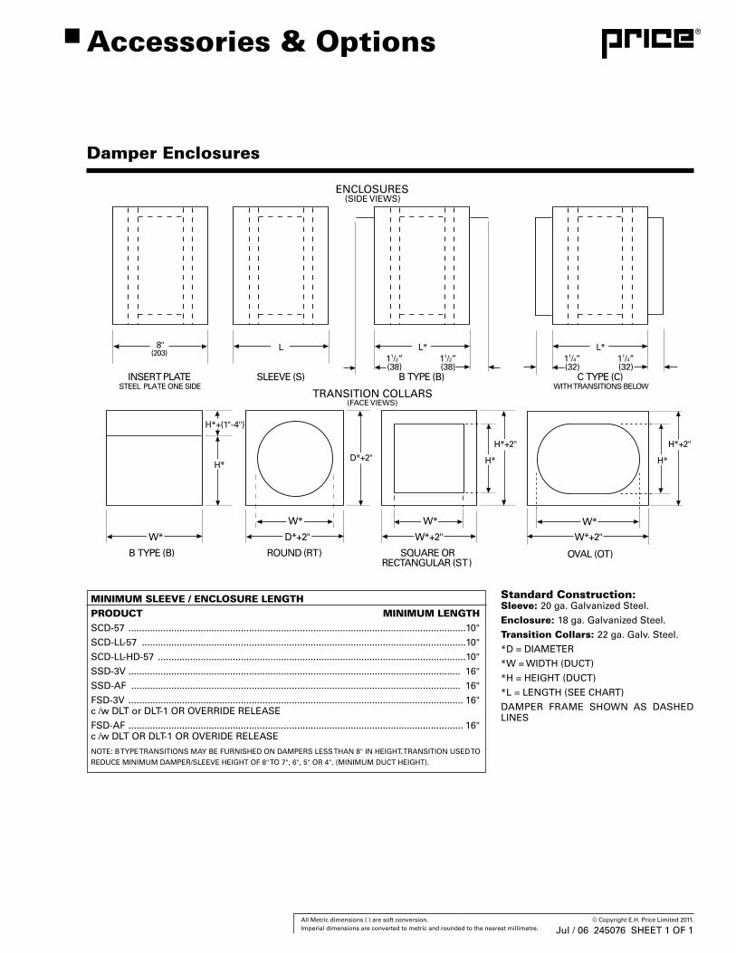
Damper Enclosures
Accessories & Options
Jul / 06 245076 SHEET 1 OF 1
Standard Construction:Sleeve: 20 ga. Galvanized Steel.
Enclosure: 18 ga. Galvanized Steel.
Transition Collars: 22 ga. Galv. Steel.
*D = DIAMETER
*W = WIDTH (DUCT)
*H = HEIGHT (DUCT)
*L = LENGTH (SEE CHART)
DAMPER FRAME SHOWN AS DASHED LINES
MINIMUM SLEEVE / ENCLOSURE LENGTHPRODUCT MINIMUM LENGTHSCD-57 ..............................................................................................................................10"
SCD-LL-57 .........................................................................................................................10"
SCD-LL-HD-57 ...................................................................................................................10"
SSD-3V ............................................................................................................................ 16"
SSD-AF ........................................................................................................................... 16"
FSD-3V ............................................................................................................................. 16"c /w DLT or DLT-1 OR OVERRIDE RELEASE
FSD-AF ............................................................................................................................. 16"c /w DLT OR DLT-1 OR OVERIDE RELEASE
NOTE: B TYPE TRANSITIONS MAY BE FURNISHED ON DAMPERS LESS THAN 8" IN HEIGHT. TRANSITION USED TO
REDUCE MINIMUM DAMPER/SLEEVE HEIGHT OF 8" TO 7", 6", 5" OR 4". (MINIMUM DUCT HEIGHT).
53 All Metric dimensions ( ) are soft conversion. © Copyright E.H. Price Limited 2011. Imperial dimensions are converted to metric and rounded to the nearest millimetre.
Jul / 06
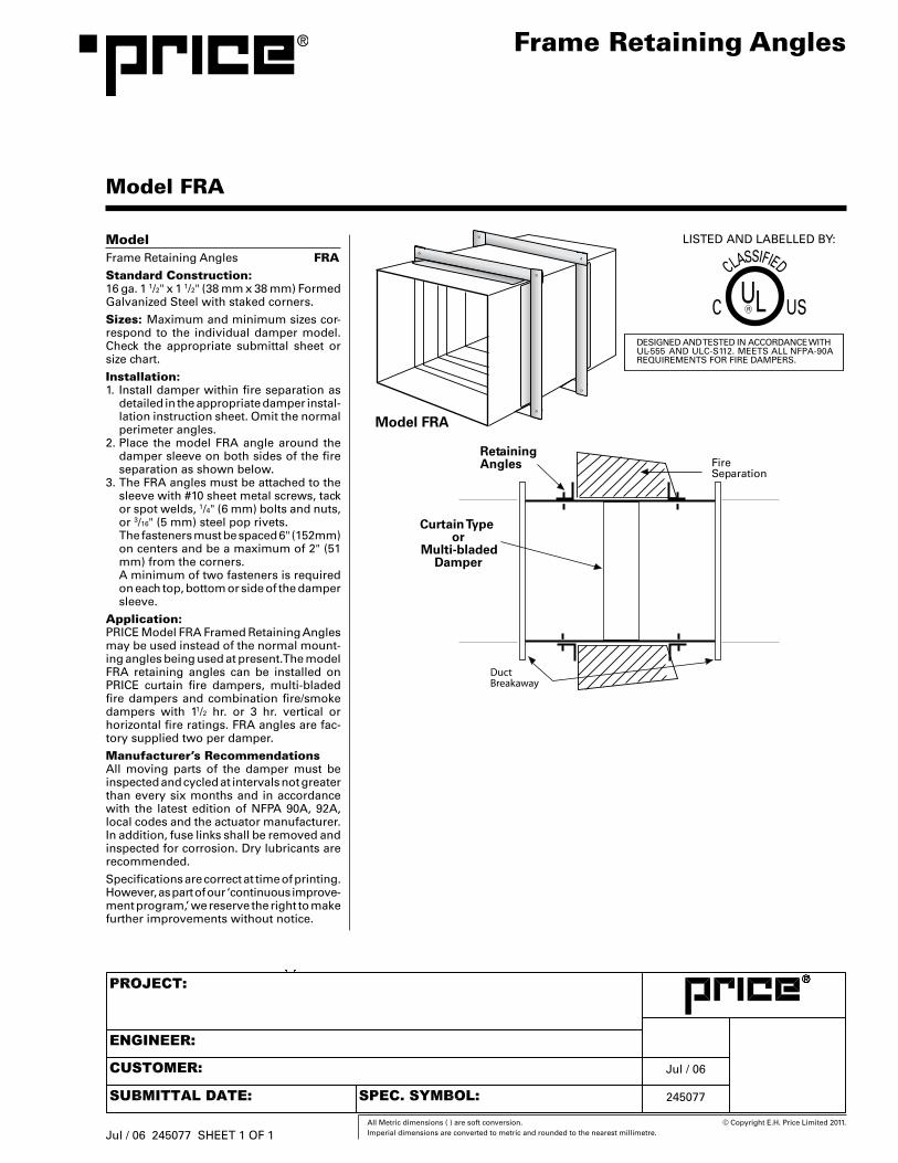
ModelFrame Retaining Angles FRAStandard Construction:16 ga. 1 1/2" x 1 1/2" (38 mm x 38 mm) Formed Galvanized Steel with staked corners.
Sizes: Maximum and minimum sizes cor-respond to the individual damper model. Check the appropriate submittal sheet or size chart.
Installation:1. Install damper within fire separation as
detailed in the appropriate damper instal-lation instruction sheet. Omit the normal perimeter angles.
2. Place the model FRA angle around the damper sleeve on both sides of the fire separation as shown below.
3. The FRA angles must be attached to the sleeve with #10 sheet metal screws, tack or spot welds, 1/4" (6 mm) bolts and nuts, or 3/16" (5 mm) steel pop rivets.
The fasteners must be spaced 6" (152mm) on centers and be a maximum of 2" (51 mm) from the corners.
A minimum of two fasteners is required on each top, bottom or side of the damper sleeve.
Application:PRICE Model FRA Framed Retaining Angles may be used instead of the normal mount-ing angles being used at present. The model FRA retaining angles can be installed on PRICE curtain fire dampers, multi-bladed fire dampers and combination fire/smoke dampers with 11/2 hr. or 3 hr. vertical or horizontal fire ratings. FRA angles are fac-tory supplied two per damper.
Manufacturer’s RecommendationsAll moving parts of the damper must be inspected and cycled at intervals not greater than every six months and in accordance with the latest edition of NFPA 90A, 92A, local codes and the actuator manufacturer. In addition, fuse links shall be removed and inspected for corrosion. Dry lubricants are recommended.
Specifications are correct at time of printing. However, as part of our ‘continuous improve-ment program,’ we reserve the right to make further improvements without notice.
Frame Retaining Angles
Model FRA
Jul / 06 245077 SHEET 1 OF 1
245077
54 All Metric dimensions ( ) are soft conversion. © Copyright E.H. Price Limited 2011. Imperial dimensions are converted to metric and rounded to the nearest millimetre.
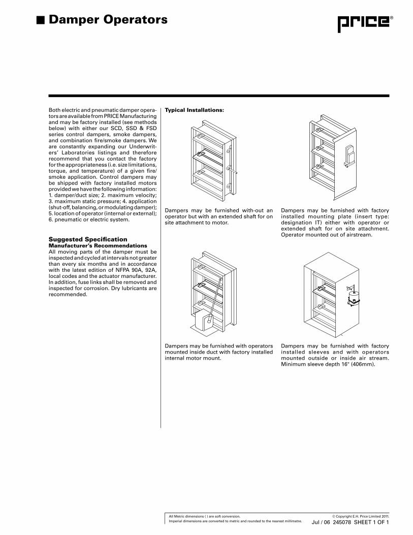
Both electric and pneumatic damper opera-tors are available from PRICE Manufacturing and may be factory installed (see methods below) with either our SCD, SSD & FSD series control dampers, smoke dampers, and combination fire/smoke dampers. We are constantly expanding our Underwrit-ers’ Laboratories listings and therefore recommend that you contact the factory for the appropriateness (i.e. size limitations, torque, and temperature) of a given fire/smoke application. Control dampers may be shipped with factory installed motors provided we have the following information: 1. damper/duct size; 2. maximum velocity; 3. maximum static pressure; 4. application (shut-off, balancing, or modulating damper); 5. location of operator (internal or external); 6. pneumatic or electric system.
Suggested SpecificationManufacturer’s RecommendationsAll moving parts of the damper must be inspected and cycled at intervals not greater than every six months and in accordance with the latest edition of NFPA 90A, 92A, local codes and the actuator manufacturer. In addition, fuse links shall be removed and inspected for corrosion. Dry lubricants are recommended.
Dampers may be furnished with factory installed sleeves and with operators mounted outside or inside air stream. Minimum sleeve depth 16" (406mm).
Dampers may be furnished with-out an operator but with an extended shaft for on site attachment to motor.
Dampers may be furnished with factory installed mounting plate (insert type: designation IT) either with operator or extended shaft for on site attachment. Operator mounted out of airstream.
Dampers may be furnished with operators mounted inside duct with factory installed internal motor mount.
Damper Operators
Jul / 06 245078 SHEET 1 OF 1
Typical Installations:
55 All Metric dimensions ( ) are soft conversion. © Copyright E.H. Price Limited 2006. Imperial dimensions are converted to metric and rounded to the nearest millimetre.
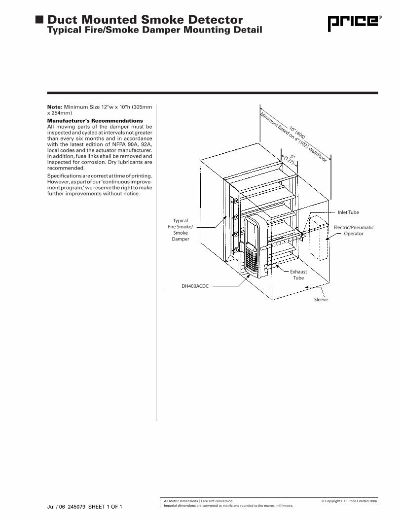
Note: Minimum Size 12"w x 10"h (305mm x 254mm)
Manufacturer’s RecommendationsAll moving parts of the damper must be inspected and cycled at intervals not greater than every six months and in accordance with the latest edition of NFPA 90A, 92A, local codes and the actuator manufacturer. In addition, fuse links shall be removed and inspected for corrosion. Dry lubricants are recommended.
Specifications are correct at time of printing. However, as part of our ‘continuous improve-ment program,’ we reserve the right to make further improvements without notice.
Duct Mounted Smoke Detector Typical Fire/Smoke Damper Mounting Detail
Jul / 06 245079 SHEET 1 OF 1
57 All Metric dimensions ( ) are soft conversion. © Copyright E.H. Price Limited 2011. Imperial dimensions are converted to metric and rounded to the nearest millimetre.
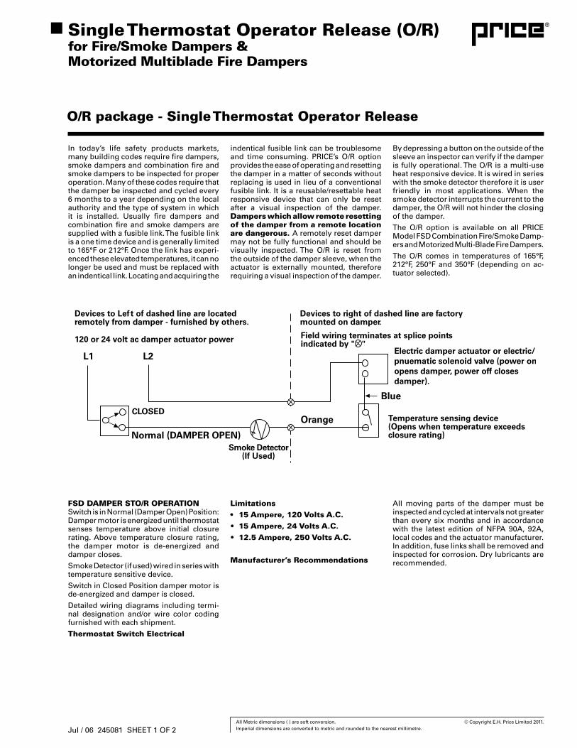
In today’s life safety products markets, many building codes require fire dampers, smoke dampers and combination fire and smoke dampers to be inspected for proper operation. Many of these codes require that the damper be inspected and cycled every 6 months to a year depending on the local authority and the type of system in which it is installed. Usually fire dampers and combination fire and smoke dampers are supplied with a fusible link. The fusible link is a one time device and is generally limited to 165°F or 212°F. Once the link has experi-enced these elevated temperatures, it can no longer be used and must be replaced with an indentical link. Locating and acquiring the
O/R package - Single Thermostat Operator Release
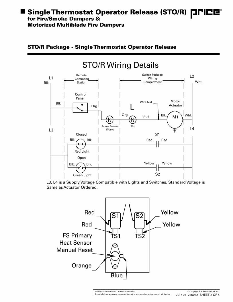
FSD DAMPER STO/R OPERATIONSwitch is in Normal (Damper Open) Position: Damper motor is energized until thermostat senses temperature above initial closure rating. Above temperature closure rating, the damper motor is de-energized and damper closes.
Smoke Detector (if used) wired in series with temperature sensitive device.
Switch in Closed Position damper motor is de-energized and damper is closed.
Detailed wiring diagrams including termi-nal designation and/or wire color coding furnished with each shipment.
Thermostat Switch Electrical
Limitations• 15 Ampere, 120 Volts A.C.• 15 Ampere, 24 Volts A.C.• 12.5 Ampere, 250 Volts A.C.
Manufacturer’s Recommendations
indentical fusible link can be troublesome and time consuming. PRICE’s O/R option provides the ease of operating and resetting the damper in a matter of seconds without replacing is used in lieu of a conventional fusible link. It is a reusable/resettable heat responsive device that can only be reset after a visual inspection of the damper. Dampers which allow remote resetting of the damper from a remote location are dangerous. A remotely reset damper may not be fully functional and should be visually inspected. The O/R is reset from the outside of the damper sleeve, when the actuator is externally mounted, therefore requiring a visual inspection of the damper.
By depressing a button on the outside of the sleeve an inspector can verify if the damper is fully operational. The O/R is a multi-use heat responsive device. It is wired in series with the smoke detector therefore it is user friendly in most applications. When the smoke detector interrupts the current to the damper, the O/R will not hinder the closing of the damper.
The O/R option is available on all PRICE Model FSD Combination Fire/Smoke Damp-ers and Motorized Multi-Blade Fire Dampers.
The O/R comes in temperatures of 165°F, 212°F, 250°F and 350°F (depending on ac-tuator selected).
All moving parts of the damper must be inspected and cycled at intervals not greater than every six months and in accordance with the latest edition of NFPA 90A, 92A, local codes and the actuator manufacturer. In addition, fuse links shall be removed and inspected for corrosion. Dry lubricants are recommended.
Single Thermostat Operator Release (O/R)for Fire/Smoke Dampers & Motorized Multiblade Fire Dampers
Jul / 06 245081 SHEET 1 OF 2
58 All Metric dimensions ( ) are soft conversion. © Copyright E.H. Price Limited 2011. Imperial dimensions are converted to metric and rounded to the nearest millimetre.
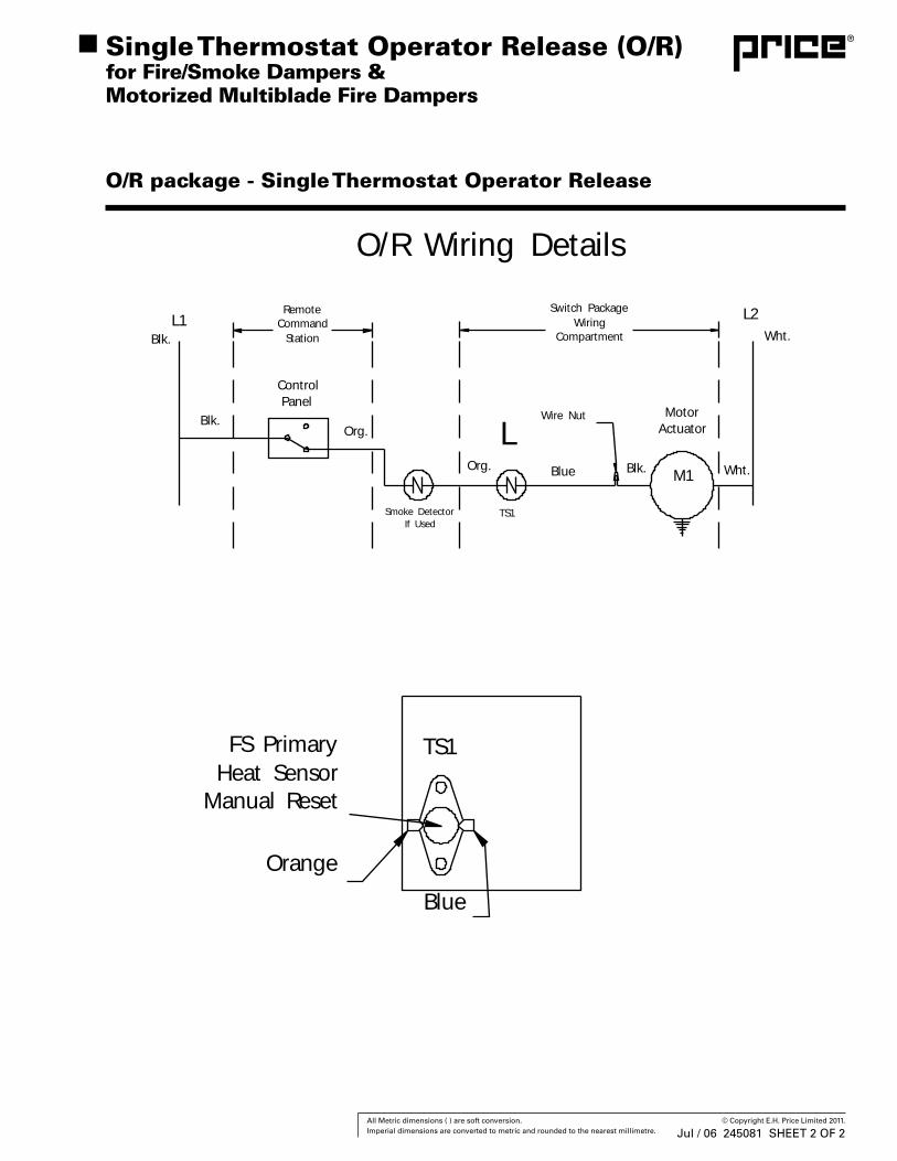
Org.
O/R Wiring Details
Switch PackageWiring
Compartment
FS PrimaryHeat Sensor
Manual Reset
Orange
Blue
TS1
ControlPanel
RemoteCommand
StationL1
Blk.
Blk.
Smoke DetectorIf Used
Org.Motor
Actuator
TS1
Wire Nut
Blue
LBlk. M1 Wht.
L2Wht.
O/R package - Single Thermostat Operator Release
Single Thermostat Operator Release (O/R) for Fire/Smoke Dampers & Motorized Multiblade Fire Dampers
Jul / 06 245081 SHEET 2 OF 2
59 All Metric dimensions ( ) are soft conversion. © Copyright E.H. Price Limited 2011. Imperial dimensions are converted to metric and rounded to the nearest millimetre.
In today’s life safety products markets, many building codes require fire dampers, smoke dampers and combination fire and smoke dampers to be inspected for proper operation. Many of these codes require that the damper be inspected and cycled every 6 months to a year depending on the local authority and the type of system in which it is installed. Usually fire dampers and combination fire and smoke dampers are supplied with a fusible link. The fusible link is a one time device and is generally limited to 165°F or 212°F. Once the link has experienced these elevated temperatures, it can no longer be used and must be replaced with an identical link. Locating and acquiring
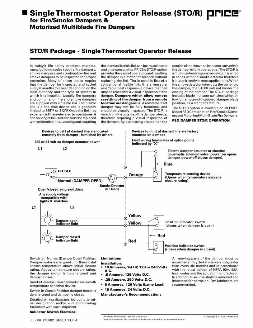
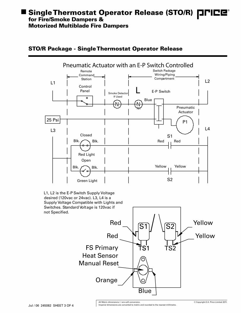
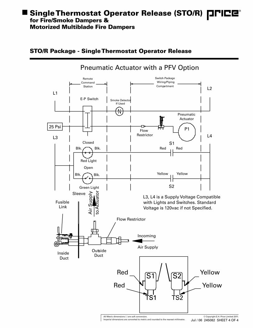
Switch is in Normal (Damper Open) Position: Damper motor is energized until thermostat senses temperature above initial closure rating. Above temperature closure rating, the damper motor is de-energized and damper closes.
Smoke Detector (if used) wired in series with temperature sensitive device.
Switch in Closed Position damper motor is de-energized and damper is closed.
Detailed wiring diagrams including termi-nal designation and/or wire color coding furnished with each shipment.
Indicator Switch Electrical
LimitationsInstallation:• 10 Amperes, 1/4 HP, 120 or 240 Volts
A.C.• .5 Ampere, 125 Volts D.C.• .25 Ampere, 250 Volts D.C.• 5 Amperes, 120 Volts (Lamp Load)• 15 Amperes, 24 Volts D.C.Manufacturer’s Recommendations
STO/R Package - Single Thermostat Operator Release
the identical fusible link can be troublesome and time consuming. PRICE’s STO/R option provides the ease of operating and resetting the damper in a matter of seconds without replacing the link. The is used in lieu of a conventional fusible link. It is a reusable/resettable heat responsive device that can only be reset after a visual inspection of the damper. Dampers which allow remote resetting of the damper from a remote location are dangerous. A remotely reset damper may not be fully functional and should be visually inspected. The STO/R is reset from the outside of the damper sleeve, therefore requiring a visual inspection of the damper. By depressing a button on the
outside of the sleeve an inspector can verify if the damper is fully operational. The STO/R is a multi-use heat responsive device. It is wired in series with the smoke detector therefore it is user friendly in most applications. When the smoke detector interrupts the current to the damper, the STO/R will not hinder the closing of the damper. The STO/R package includes blade indicator switches which al-low for remote notification of damper blade position, as a standard feature.
The STO/R option is available on all PRICE Model FSD Combination Fire/Smoke Damp-ers and Motorized Multi-Blade Fire Dampers.
FSD DAMPER STO/R OPERATION
All moving parts of the damper must be inspected and cycled at intervals not greater than every six months and in accordance with the latest edition of NFPA 90A, 92A, local codes and the actuator manufacturer. In addition, fuse links shall be removed and inspected for corrosion. Dry lubricants are recommended.
Single Thermostat Operator Release (STO/R)for Fire/Smoke Dampers &Motorized Multiblade Fire Dampers
Jul / 06 245082 SHEET 1 OF 4
60 All Metric dimensions ( ) are soft conversion. © Copyright E.H. Price Limited 2011. Imperial dimensions are converted to metric and rounded to the nearest millimetre.
Single Thermostat Operator Release (STO/R) for Fire/Smoke Dampers & Motorized Multiblade Fire Dampers
STO/R Package - Single Thermostat Operator Release
Jul / 06 245082 SHEET 2 OF 4
61 All Metric dimensions ( ) are soft conversion. © Copyright E.H. Price Limited 2011. Imperial dimensions are converted to metric and rounded to the nearest millimetre.
Single Thermostat Operator Release (STO/R) for Fire/Smoke Dampers & Motorized Multiblade Fire Dampers
STO/R Package - Single Thermostat Operator Release
Jul / 06 245082 SHEET 3 OF 4
62 All Metric dimensions ( ) are soft conversion. © Copyright E.H. Price Limited 2011. Imperial dimensions are converted to metric and rounded to the nearest millimetre.
Single Thermostat Operator Release (STO/R) for Fire/Smoke Dampers & Motorized Multiblade Fire Dampers
STO/R Package - Single Thermostat Operator Release
Jul / 06 245082 SHEET 4 OF 4
63 All Metric dimensions ( ) are soft conversion. © Copyright E.H. Price Limited 2011. Imperial dimensions are converted to metric and rounded to the nearest millimetre.
Prior to today’s advancements in smoke control techniques, fan systems were re-quired to shut down during fire conditions and fire dampers were closed by heat. Air pressures were not utilized for the control and containment of smoke. In recent years, the requirement that systems completely shut down and fire dampers close and re-main closed during fire conditions has been questioned. With the current engineered smoke control systems simple closure of a fire damper at a specific temperature is no longer the absolute requirement. Combina-
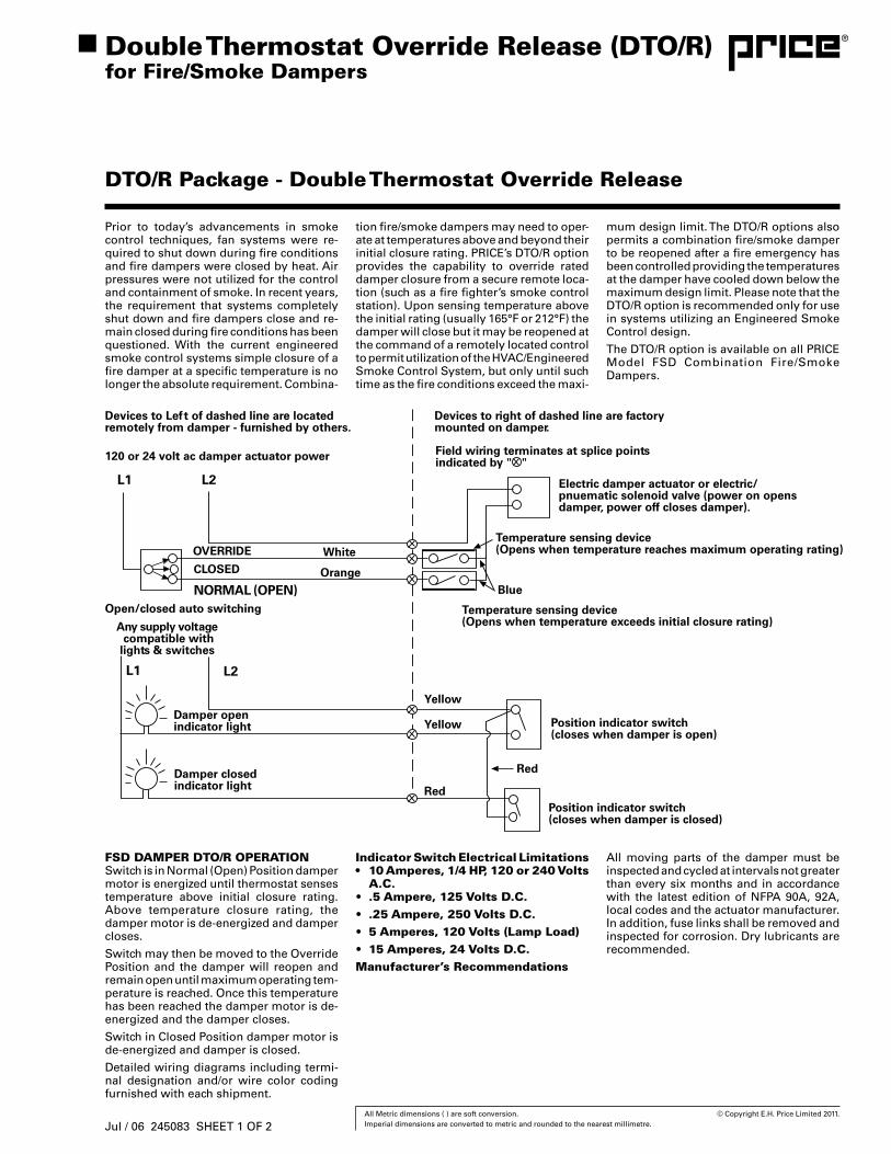
FSD DAMPER DTO/R OPERATIONSwitch is in Normal (Open) Position damper motor is energized until thermostat senses temperature above initial closure rating. Above temperature closure rating, the damper motor is de-energized and damper closes.
Switch may then be moved to the Override Position and the damper will reopen and remain open until maximum operating tem-perature is reached. Once this temperature has been reached the damper motor is de-energized and the damper closes.
Switch in Closed Position damper motor is de-energized and damper is closed.
Detailed wiring diagrams including termi-nal designation and/or wire color coding furnished with each shipment.
Indicator Switch Electrical Limitations• 10 Amperes, 1/4 HP, 120 or 240 Volts
A.C.• .5 Ampere, 125 Volts D.C.• .25 Ampere, 250 Volts D.C.• 5 Amperes, 120 Volts (Lamp Load)• 15 Amperes, 24 Volts D.C.Manufacturer’s Recommendations
DTO/R Package - Double Thermostat Override Release
tion fire/smoke dampers may need to oper-ate at temperatures above and beyond their initial closure rating. PRICE’s DTO/R option provides the capability to override rated damper closure from a secure remote loca-tion (such as a fire fighter’s smoke control station). Upon sensing temperature above the initial rating (usually 165°F or 212°F) the damper will close but it may be reopened at the command of a remotely located control to permit utilization of the HVAC/Engineered Smoke Control System, but only until such time as the fire conditions exceed the maxi-
mum design limit. The DTO/R options also permits a combination fire/smoke damper to be reopened after a fire emergency has been controlled providing the temperatures at the damper have cooled down below the maximum design limit. Please note that the DTO/R option is recommended only for use in systems utilizing an Engineered Smoke Control design.
The DTO/R option is available on all PRICE Model FSD Combination Fire/Smoke Dampers.
All moving parts of the damper must be inspected and cycled at intervals not greater than every six months and in accordance with the latest edition of NFPA 90A, 92A, local codes and the actuator manufacturer. In addition, fuse links shall be removed and inspected for corrosion. Dry lubricants are recommended.
Double Thermostat Override Release (DTO/R)for Fire/Smoke Dampers
Jul / 06 245083 SHEET 1 OF 2

64 All Metric dimensions ( ) are soft conversion. © Copyright E.H. Price Limited 2011. Imperial dimensions are converted to metric and rounded to the nearest millimetre.
DTO/R Package - Double Thermostat Override Release
Double Thermostat Override Release (DTO/R)for Fire/Smoke Dampers
Jul / 06 245083 SHEET 2 OF 2
65 All Metric dimensions ( ) are soft conversion. © Copyright E.H. Price Limited 2011. Imperial dimensions are converted to metric and rounded to the nearest millimetre.
Jul / 06
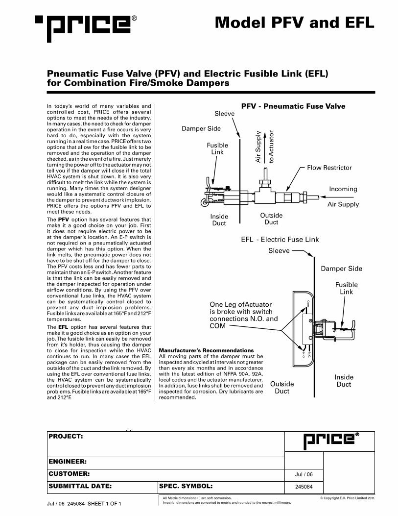
In today’s world of many variables and controlled cost, PRICE offers several options to meet the needs of the industry. In many cases, the need to check for damper operation in the event a fire occurs is very hard to do, especially with the system running in a real time case. PRICE offers two options that allow for the fusible link to be removed and the operation of the damper checked, as in the event of a fire. Just merely turning the power off to the actuator may not tell you if the damper will close if the total HVAC system is shut down. It is also very difficult to melt the link while the system is running. Many times the system designer would like a systematic control closure of the damper to prevent ductwork implosion. PRICE offers the options PFV and EFL to meet these needs.
The PFV option has several features that make it a good choice on your job. First it does not require electric power to be at the damper’s location. An E-P switch is not required on a pneumatically actuated damper which has this option. When the link melts, the pneumatic power does not have to be shut off for the damper to close. The PFV costs less and has fewer parts to maintain than an E-P switch. Another feature is that the link can be easily removed and the damper inspected for operation under airflow conditions. By using the PFV over conventional fuse links, the HVAC system can be systematically control closed to prevent any duct implosion problems. Fusible links are available at 165°F and 212°F temperatures.
The EFL option has several features that make it a good choice as an option on your job. The fusible link can easily be removed from it’s holder, thus causing the damper to close for inspection while the HVAC continues to run. In many cases the EFL package can be easily removed from the outside of the duct and the link removed. By using the EFL over conventional fuse links, the HVAC system can be systematically control closed to prevent any duct implosion problems. Fusible links are available at 165°F and 212°F.
Model PFV and EFL
Pneumatic Fuse Valve (PFV) and Electric Fusible Link (EFL) for Combination Fire/Smoke Dampers
Manufacturer’s RecommendationsAll moving parts of the damper must be inspected and cycled at intervals not greater than every six months and in accordance with the latest edition of NFPA 90A, 92A, local codes and the actuator manufacturer. In addition, fuse links shall be removed and inspected for corrosion. Dry lubricants are recommended.
Jul / 06 245084 SHEET 1 OF 1
245084
66 All Metric dimensions ( ) are soft conversion. © Copyright E.H. Price Limited 2011. Imperial dimensions are converted to metric and rounded to the nearest millimetre.
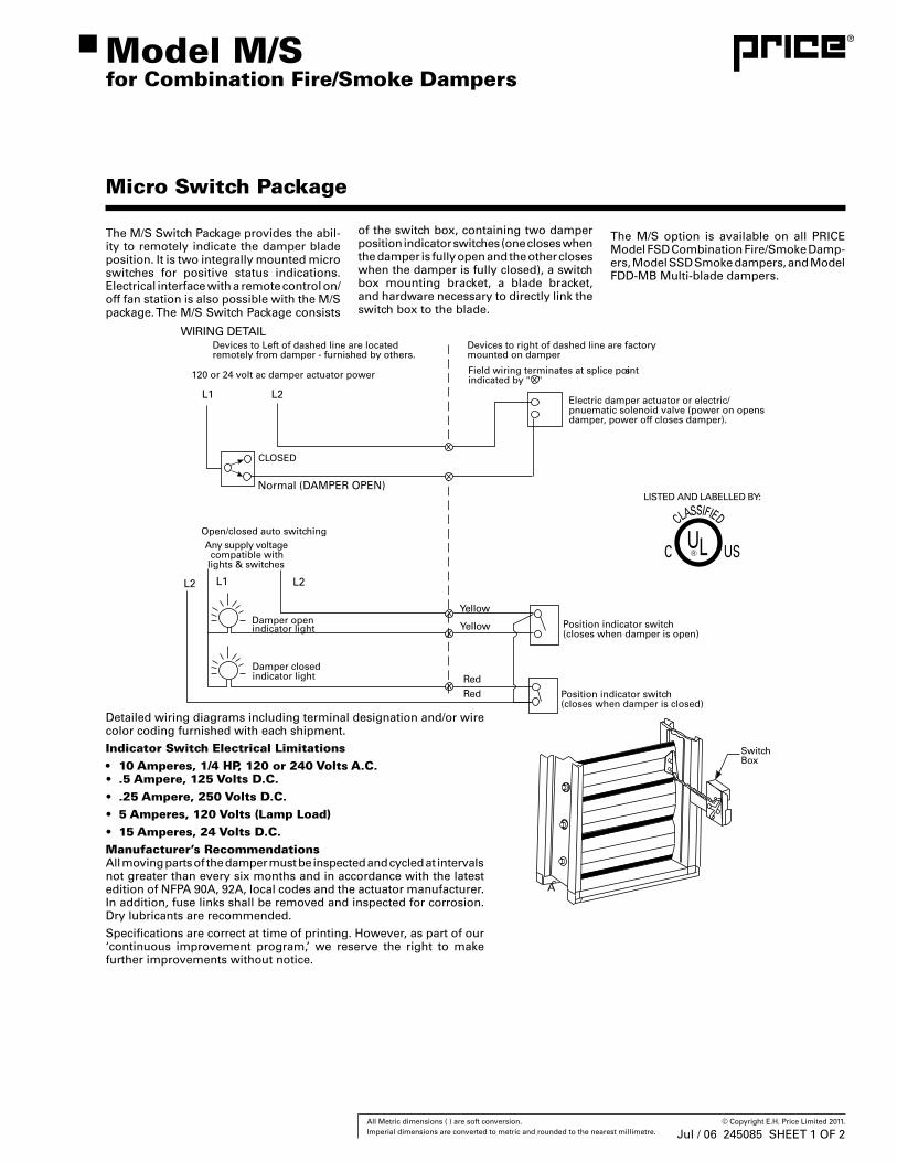
The M/S Switch Package provides the abil-ity to remotely indicate the damper blade position. It is two integrally mounted micro switches for positive status indications. Electrical interface with a remote control on/off fan station is also possible with the M/S package. The M/S Switch Package consists
Detailed wiring diagrams including terminal designation and/or wire color coding furnished with each shipment.
Indicator Switch Electrical Limitations• 10 Amperes, 1/4 HP, 120 or 240 Volts A.C.• .5 Ampere, 125 Volts D.C.• .25 Ampere, 250 Volts D.C.• 5 Amperes, 120 Volts (Lamp Load)• 15 Amperes, 24 Volts D.C.Manufacturer’s RecommendationsAll moving parts of the damper must be inspected and cycled at intervals not greater than every six months and in accordance with the latest edition of NFPA 90A, 92A, local codes and the actuator manufacturer. In addition, fuse links shall be removed and inspected for corrosion. Dry lubricants are recommended.
Specifications are correct at time of printing. However, as part of our ‘continuous improvement program,’ we reserve the right to make further improvements without notice.
Model M/Sfor Combination Fire/Smoke Dampers
Micro Switch Package
of the switch box, containing two damper position indicator switches (one closes when the damper is fully open and the other closes when the damper is fully closed), a switch box mounting bracket, a blade bracket, and hardware necessary to directly link the switch box to the blade.
The M/S option is available on all PRICE Model FSD Combination Fire/Smoke Damp-ers, Model SSD Smoke dampers, and Model FDD-MB Multi-blade dampers.
Jul / 06 245085 SHEET 1 OF 2

67 All Metric dimensions ( ) are soft conversion. © Copyright E.H. Price Limited 2011. Imperial dimensions are converted to metric and rounded to the nearest millimetre.
Micro Switch Package
Model M/Sfor Combination Fire/Smoke Dampers
Jul / 06 245085 SHEET 2 OF 2

70 All Metric dimensions ( ) are soft conversion. © Copyright E.H. Price Limited 2011. Imperial dimensions are converted to metric and rounded to the nearest millimetre.
Agency Listings
4-Wire Photoelectric Duct Smoke Detector
The InnovairFlex™ Series are the only duct smoke
detectors flexible enough to fit configurations from
square to rectangular and everything in between.
FeaturesPhotoelectric, integrated low-flow technology•
Air velocity rating from 100 ft/min to 4,000 ft/min (0.5 m/s to 20.32 • m/sec)
Versatile mounting options: square or rectangular configuration•
Plug-in sensor offers superb false alarm immunity and the latest • sensor technology
Broad ranges for operating temperature (–4°F to 158°F) and • humidity (0% to 95% non-condensing)
Patented sampling tube installs from front or back of the detector • with no tools required
Increased wiring space with a newly added ¾-inch conduit • knockout
One easy-access Test/Reset button and improved LED status•
Patented interconnect feature for multi-fan shutdown •
New high contrast terminal designations•
Built-in short circuit protection from operator wiring errors •
Field selectable settings for configuring the detector•
Two DPDT Form-C relay contacts•
24 VAC/DC or 120VAC •
Backward compatibility with existing Innovair products, including • remote accessories
The InnovairFlex D4120A 4-wire photoelectric duct smoke detector features a pivoting housing that fits both square and rectangular footprints and mounts to round or rectangular ductwork. This unit senses smoke in the most challenging conditions, operating in airflow speeds of 100 to 4,000 feet per minute, temperatures of –4°F to 158°F, and a humidity range of 0 to 95 percent (non-condensing). A plug-in sensor head offers improved false alarm immunity and simple installation, testing, and maintenance. An improved cover design isolates the sensor head from the low-flow feature for simple maintenance.
The InnovairFlex housing provides ample wiring space, a ¾-inch conduit knockout, and built-in short circuit protection to prevent damage to sensitive components during installation. High contrast terminal designations make wiring easy. With its 2:1 sensor-to-power capability, the power board of the D4120A may be used to monitor a second sensor ,D4SA, simultaneously (i.e., supply and return side). As many as 50 InnovairFlex detectors can be interconnected. When one unit senses smoke, all interconnected detectors will switch their relays; only the detector sensing smoke will go into alarm, thus pinpointing the fire source.
An easy-access Test/Reset button makes it possible to test the unit with the cover on. Three DIP switches can be used to configure field selectable settings: cover tamper delay, number of sensors to be controlled, and shut down on trouble option. Each power board has two LEDs that can be used to indicate the status of connected sensors, and a quick reference imprinted on the cover explains the LED status indications (Standby, Maintenance, Trouble, and Alarm). The InnovairFlex duct smoke detector can be customized to meet local codes and specifications without additional wiring. The new InnovairFlex product line is compatible with all previous Innovair models, including remote test accessories.
WARNING: Duct smoke detectors are NOT a substitute for open area smoke detectors; NOT a substitute for early warning detection; NOT a replacement for a building’s regular fire detection system. Refer to NFPA 72 and 90A and CAN/ULC S524 for additional information.APPROVED

71 All Metric dimensions ( ) are soft conversion. © Copyright E.H. Price Limited 2011. Imperial dimensions are converted to metric and rounded to the nearest millimetre.
A05-0419-000
InnovairFlex™ Duct Smoke Detector SpecificationsArchitectural/Engineering Specifications
The air duct smoke detector shall be a System Sensor InnovairFlex™ D4120A Photoelectric Duct Smoke Detector. The detector housing shall be ULC listed specifically for use in air handling systems. The flexible housing of the duct smoke detector fits multiple footprints from square to rectangular. The detector shall operate at air velocities of 100 feet per minute to 4000 feet per minute (0.5 to 20.32 meters/second). The unit shall be capable of controlling up to 50 air handling systems when interconnected with other detectors. The detector shall be capable of providing a trouble signal in the event that the front cover is removed. It shall be capable of local testing via magnetic switch, test button on the cover, or remote testing using the RTS451KEYA Remote Test Station. Terminal connections shall be of the strip and clamp method suitable for 12–18 AWG wiring.
Physical Specifications
Size: (Rectangular Dimensions) (Square Dimensions)
14.38 in (37 cm) Length; 5 in (12.74 cm) Width; 2.5 in (6.36 cm) Depth7.75 in (19.7 cm) Length; 9 in (22.9 cm) Width; 2.5 in (6.35 cm) Depth
Weight: 2.5 lbs (1.14 kg)
Operating Temperature Range: D4120A & D4SA: –20° to 70°C (–4° to 158°F); D4P120A: –40° to 70°C (–40° to 158°F)
Storage Temperature Range: D4120A & D4SA: –30° to 70°C (–22° to 158°F); D4P120A: –40° to 70°C (–40° to 158°F)
Operating Humidity Range: 0% to 95% relative humidity non-condensing
Air Duct Velocity: 100 to 4000 ft/min (0.5 to 20.32 m/sec)
Electrical Ratings
Power supply voltage: 20–29 VDC 24 VAC 50–60 Hz 120 VAC 50–60 Hz
Input capacitance: 270 µF max. 270 µF max. N/A
Reset voltage: 3.0 VDC min. 2.0 VAC min. 10 VAC min.
Reset time: (with RTS451) .03 to 0.3 sec. .03 to 0.3 sec. .03 to 0.3 sec.
Reset time: (by power down) 0.6 sec. max. 0.6 sec. max. 0.6 sec. max.
Power up time: 35 sec. max. 35 sec. max. 35 sec. max.
Alarm response time: 15 sec. 15 sec. 15 sec.
Sensitivity Test: See detector label See detector label See detector label
Current Requirements: (Using No Accessories)
Max. standby current: 21 mA @ 24VDC 65 mA RMS @ 24VAC 60Hz 20 mA RMS @ 120VAC 60Hz
Max. alarm current: 65 mA @ 24VDC 135 mA RMS @ 24VAC 60Hz 35 mA RMS @ 120VAC 60Hz
Contact Ratings
Alarm initiation contacts: (SPST) 2.0A @ 30 VDC (resistive)
Alarm auxiliary contacts: (DPDT) 10A @ 30 VDC (resistive); 10A @ 250 VAC (resistive); ½ HP @ 240 VAC ; ¼ HP @ 120 VAC
Note: Alarm auxiliary contacts shall not be connected to initiating circuits of control panels. Use the alarm initiation contact for this purpose.
Supervisory contacts: (SPDT) 2.0A @ 30 VDC (resistive); 2.0A @ 125 VAC (resistive)
Accessory Current Loads at 24 VDC
Device Standby Trouble Alarm
MHRA/MHWA 0 mA n/a 29 mA Max.
RA400ZA 0 mA n/a 12 mA Max.
RTS451/RTS451KEYA 0 mA/12 mA n/a 12 mA Max.
Note: Any combination of accessories may be used such that the given accessory loads are: 110 mA or less at the Aux output, and 50 mA or less at the Alarm output
Installing the InnovairFlex Sampling TubeThe InnovairFlex sampling tube may be installed from the front or back of the detector. The tube locks securely into place and can be removed by releasing the front or rear locking tab (front locking tab shown below right).
72 All Metric dimensions ( ) are soft conversion. © Copyright E.H. Price Limited 2011. Imperial dimensions are converted to metric and rounded to the nearest millimetre.
A05-0419-000
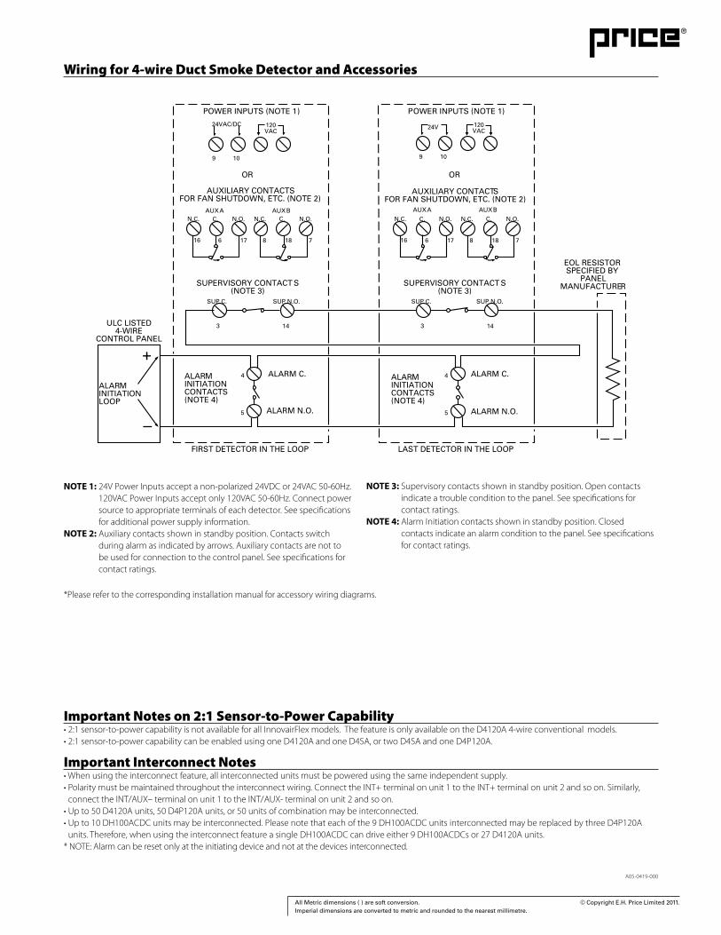
Wiring for 4-wire Duct Smoke Detector and Accessories
Important Notes on 2:1 Sensor-to-Power Capability• 2:1 sensor-to-power capability is not available for all InnovairFlex models. The feature is only available on the D4120A 4-wire conventional models. • 2:1 sensor-to-power capability can be enabled using one D4120A and one D4SA, or two D4SA and one D4P120A.
Important Interconnect Notes• When using the interconnect feature, all interconnected units must be powered using the same independent supply.• Polarity must be maintained throughout the interconnect wiring. Connect the INT+ terminal on unit 1 to the INT+ terminal on unit 2 and so on. Similarly,
connect the INT/AUX– terminal on unit 1 to the INT/AUX- terminal on unit 2 and so on.• Up to 50 D4120A units, 50 D4P120A units, or 50 units of combination may be interconnected.• Up to 10 DH100ACDC units may be interconnected. Please note that each of the 9 DH100ACDC units interconnected may be replaced by three D4P120A
units. Therefore, when using the interconnect feature a single DH100ACDC can drive either 9 DH100ACDCs or 27 D4120A units.* NOTE: Alarm can be reset only at the initiating device and not at the devices interconnected.
NOTE 1: 24V Power Inputs accept a non-polarized 24VDC or 24VAC 50-60Hz. 120VAC Power Inputs accept only 120VAC 50-60Hz. Connect power source to appropriate terminals of each detector. See specifications for additional power supply information.
NOTE 2: Auxiliary contacts shown in standby position. Contacts switch during alarm as indicated by arrows. Auxiliary contacts are not to be used for connection to the control panel. See specifications for contact ratings.
NOTE 3: Supervisory contacts shown in standby position. Open contacts indicate a trouble condition to the panel. See specifications for contact ratings.
NOTE 4: Alarm Initiation contacts shown in standby position. Closed contacts indicate an alarm condition to the panel. See specifications for contact ratings.
*Please refer to the corresponding installation manual for accessory wiring diagrams.
24VAC/DC
9 10
AUXILIARY CONTACTSFOR FAN SHUTDOWN, ETC. (NOTE 2)
16 6 17 8 18 7
N.O.C.N.C.N.O.C.N.C.
16 6 17 8 18 7
N.O.C.N.C.N.O.C.N.C.
SUPERVISORY CONTACT S(NOTE 3)
24V
9 10
AUXILIARY CONTACTSFOR FAN SHUTDOWN, ETC. (NOTE 2)
SUPERVISORY CONTACT S(NOTE 3)
SUP C. SUP N.O. SUP N.O.SUP C.
5
4ALARMINITIATIONCONTACTS(NOTE 4)
5
4ALARMINITIATIONCONTACTS(NOTE 4)
ALARMINITIATIONLOOP
ULC LISTED4-WIRE
CONTROL PANEL
+
120VAC
120VAC
OR OR
AUX A AUX BAUX A AUX B
ALARM C.ALARM C.
ALARM N.O.ALARM N.O.
14 143 3
FIRST DETECTOR IN THE LOOP
POWER INPUTS (NOTE 1 P) OWER INPUTS (NOTE 1)
LAST DETECTOR IN THE LOOP
EOL RESISTOR SPECIFIED BY
PANEL MANUFACTURER

73 All Metric dimensions ( ) are soft conversion. © Copyright E.H. Price Limited 2011. Imperial dimensions are converted to metric and rounded to the nearest millimetre.
AccessoriesSystem Sensor provides system flexibility with a variety of accessories, including two remote test stations and several different means of visible and audible system annunciation. As with our duct smoke detectors, all duct smoke detector accessories are ULC listed.
Ordering InformationPart No. Description
D4120A 4-wire photoelectric low-flow duct smoke detector
Accessories
D4SA 4-wire photoelectric sensor component only MHRA Mini Horn, Red
D4P120A 4-wire photoelectric power board component only, 24 VAC/DC, 120 VAC
MHWA Mini Horn, White
2D51A 4-wire conventional photoelectric sensor head P48-21-00 End cap for metal sampling tubes
DST1 Metal sampling tube duct width up to 1ft (0.3m) RA400ZA Remote annunciator alarm LED
DST1.5 Metal sampling tube duct widths 1 ft to 2 ft (0.3 to 0.6 m) RTS451 Remote test station
DST3 Metal sampling tube duct widths 2 ft to 4 ft (0.6 to 1.2 m) RTS451KEYA Remote test station with key lock
DST5 Metal sampling tube duct widths 4 ft to 8 ft (1.2 to 2.4 m)
DST10 Metal sampling tube duct widths 8 ft to 12 ft (2.4 to 3.7 m)
DH400 OE-1 Weatherproof enclosure
ETX Metal exhaust tube duct width 1ft (0.3m)
M02-04-00 Test magnet
RTS451 RA400ZARTS451KEYA
MHWA MHRA
©2007 System Sensor.Product specifications subject to change without notice. Visit systemsensor.com for
current product information, including the latest version of this data sheet.A05-0414-000 • 1/07 • #1743
6-6581 Kitimat Road • Mississauga ON, L5N 3T5 Phone: 800-SENSOR2 • www.systemsensor.ca
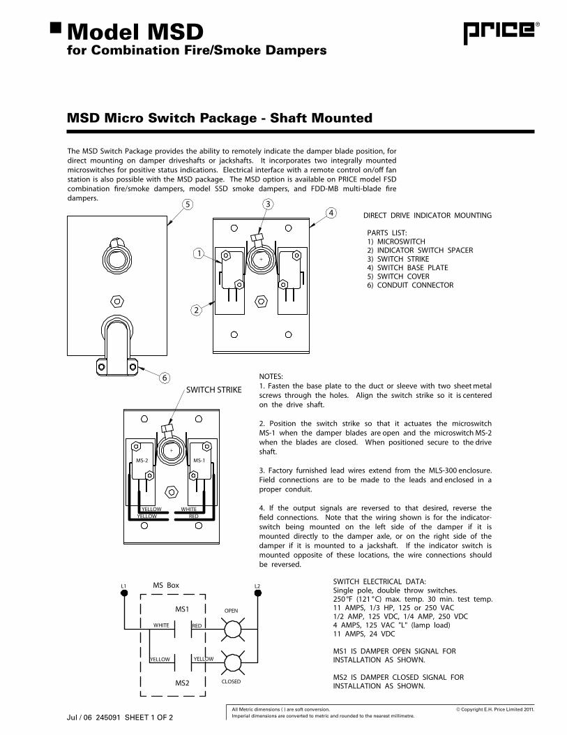
74 All Metric dimensions ( ) are soft conversion. © Copyright E.H. Price Limited 2011. Imperial dimensions are converted to metric and rounded to the nearest millimetre.
MSD Micro Switch Package - Shaft Mounted
Model MSDfor Combination Fire/Smoke Dampers
MS-1MS-2
YELLOWYELLOW
WHITERED
SWITCH STRIKE
DIRECT DRIVE INDICATOR MOUNTING
PARTS LIST: 1) MICROSWITCH 2) INDICATOR SWITCH SPACER 3) SWITCH STRIKE 4) SWITCH BASE PLATE 5) SWITCH COVER 6) CONDUIT CONNECTOR
1
2
34
5
6
SWITCH ELECTRICAL DATA:Single pole, double throw switches.250 °F (121 °C) max. temp. 30 min. test temp.11 AMPS, 1/3 HP, 125 or 250 VAC1/2 AMP, 125 VDC, 1/4 AMP, 250 VDC4 AMPS, 125 VAC "L" (lamp load)11 AMPS, 24 VDC
MS1 IS DAMPER OPEN SIGNAL FORINSTALLATION AS SHOWN.
MS2 IS DAMPER CLOSED SIGNAL FORINSTALLATION AS SHOWN.
MS1
MS2
MS Box
OPEN
CLOSED
L2L1
REDWHITE
YELLOWYELLOW
NOTES:1. Fasten the base plate to the duct or sleeve with two sheet metal screws through the holes. Align the switch strike so it is centered on the drive shaft.
2. Position the switch strike so that it actuates the microswitch MS-1 when the damper blades are open and the microswitch MS-2 when the blades are closed. When positioned secure to the drive shaft.
3. Factory furnished lead wires extend from the MLS-300 enclosure. Field connections are to be made to the leads and enclosed in a proper conduit.
4. If the output signals are reversed to that desired, reverse the �eld connections. Note that the wiring shown is for the indicator-switch being mounted on the left side of the damper if it is mounted directly to the damper axle, or on the right side of the damper if it is mounted to a jackshaft. If the indicator switch is mounted opposite of these locations, the wire connections should be reversed.
The MSD Switch Package provides the ability to remotely indicate the damper blade position, for direct mounting on damper driveshafts or jackshafts. It incorporates two integrally mounted microswitches for positive status indications. Electrical interface with a remote control on/o� fan station is also possible with the MSD package. The MSD option is available on PRICE model FSD combination �re/smoke dampers, model SSD smoke dampers, and FDD-MB multi-blade �re dampers.
Jul / 06 245091 SHEET 1 OF 2
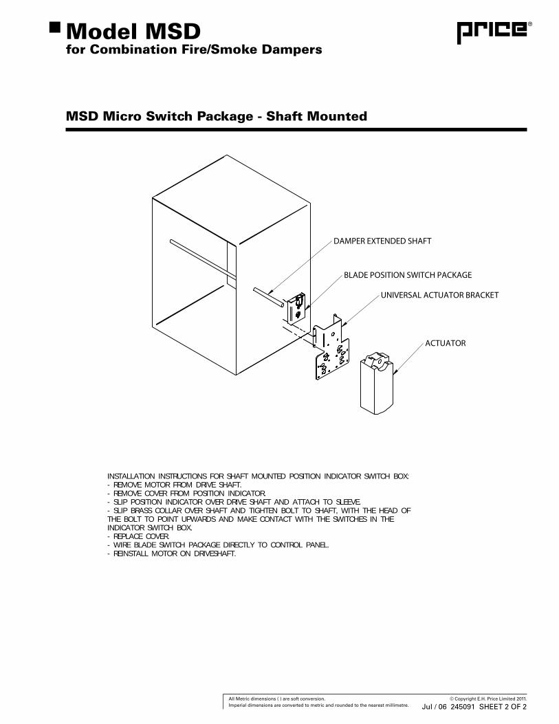
75 All Metric dimensions ( ) are soft conversion. © Copyright E.H. Price Limited 2011. Imperial dimensions are converted to metric and rounded to the nearest millimetre.
MSD Micro Switch Package - Shaft Mounted
Model MSDfor Combination Fire/Smoke Dampers
INSTALLATION INSTRUCTIONS FOR SHAFT MOUNTED POSITION INDICATOR SWITCH BOX:- REMOVE MOTOR FROM DRIVE SHAFT.- REMOVE COVER FROM POSITION INDICATOR.- SLIP POSITION INDICATOR OVER DRIVE SHAFT AND ATTACH TO SLEEVE.- SLIP BRASS COLLAR OVER SHAFT AND TIGHTEN BOLT TO SHAFT, WITH THE HEAD OFTHE BOLT TO POINT UPWARDS AND MAKE CONTACT WITH THE SWITCHES IN THEINDICATOR SWITCH BOX.- REPLACE COVER.- WIRE BLADE SWITCH PACKAGE DIRECTLY TO CONTROL PANEL.- REINSTALL MOTOR ON DRIVESHAFT.
ACTUATOR
UNIVERSAL ACTUATOR BRACKET
DAMPER EXTENDED SHAFT
BLADE POSITION SWITCH PACKAGE
Jul / 06 245091 SHEET 2 OF 2