fire protection valves - nibco.com
TRANSCRIPT
F i r e P r o t e c t i o n Va l v e s
C-FPV-1221
AHEAD OF THE F LOW ®

NIBCO INC. WORLD HEADQUARTERS • 1516 MIDDLEBURY ST. • ELKHART, IN 46516-4740 • USA • PH: 1.800.234.0227 TECH SERVICES PH:1.888.446.4226 • FAX: 1.888.336.4226 • INTERNATIONAL OFFICE PH: +1.574.295.3327 • FAX: +1.574.295.3455
www.nibco.com
The velocity with which e-business evolves demands that new products and services be continuously developed and introduced to keep our customers at the center of our business efforts. NIBCO provides an entire suite of business-to-business solutions that is changing the way we interact with customers.
Look to NIBCO for technology leadership.
Business-to-Business Solutions
NIBCOpartner.comsm is an exclusive set of secure web applications that allow quick access to customer-specific information and online order processing. This self-service approach gives you 24/7 access to your order status putting you in total control of your business.
Real time information includes:• Online order entry • Current price checks• Viewable invoices & reports • Order status• Inventory availability • Online library of price sheets, catalogs & submittals
Electronic Data Interchange (EDI) makes it possible to trade business documents at the speed of light. This technology cuts the cost of each transaction by eliminating the manual labor and paper-work involved in traditional order taking. This amounts to cost-savings, increased accuracy and better use of resources.
With EDI, you can trade:• Purchase orders • Product activity data• PO Acknowledgements • Advanced ship notices• Invoices • Remittance advice
Vendor Managed Inventory (VMI), a sophisticated service for automated inventory management, reduces your overhead by transferring inventory management, order entry and forecasting to NIBCO. This is an on-going, interactive partnership with NIBCO.
Through automation, VMI brings results:• Improves customer service • Cuts transaction costs• Optimum inventory efficiencies • Peace of mind• Better forecasting • Relief from day-to-day management
3NIBCO INC. WORLD HEADQUARTERS • 1516 MIDDLEBURY ST. • ELKHART, IN 46516-4740 • USA • PH: 1.800.234.0227
TECH SERVICES PH: 1.888.446.4226 • FAX: 1.888.336.4226 • INTERNATIONAL OFFICE PH: +1.574.295.3327 • FAX: +1.574.295.3455 www.nibco.com
Visit our website for the most current information.
www.nibco.com A H E A D O F T H E F L O W®
Table of Contents
PageBronze UL/FM Valves and Trim . . . . . . . . . . . . . . . . 4-17
Illustrated Index . . . . . . . . . . . . . . . . . . . . . . . . . . . . . . 4
T-104-O . . . . . . . . . . . . . . . . . . . . . . . . . . . . . . . . . . . . . 5
KT/KG-505 . . . . . . . . . . . . . . . . . . . . . . . . . . . . . . . . . . 6
T-103-HC . . . . . . . . . . . . . . . . . . . . . . . . . . . . . . . . . . . . 7
T-331-HC . . . . . . . . . . . . . . . . . . . . . . . . . . . . . . . . . . . . 8
KT-65-UL . . . . . . . . . . . . . . . . . . . . . . . . . . . . . . . . . . . . 9
KT-211-W-UL . . . . . . . . . . . . . . . . . . . . . . . . . . . . . . . 10
KT-67-UL . . . . . . . . . . . . . . . . . . . . . . . . . . . . . . . . . . . 11
T-301-W . . . . . . . . . . . . . . . . . . . . . . . . . . . . . . . . . . . 12
KT-291-W3 . . . . . . . . . . . . . . . . . . . . . . . . . . . . . . . . . 13
KT-403-W . . . . . . . . . . . . . . . . . . . . . . . . . . . . . . . . . . 14
T-480 . . . . . . . . . . . . . . . . . . . . . . . . . . . . . . . . . . . . . . 15
T-585-70 . . . . . . . . . . . . . . . . . . . . . . . . . . . . . . . . . . . 16
KT-580/585-70-UL . . . . . . . . . . . . . . . . . . . . . . . . . . . 17
Iron UL/FM Valves . . . . . . . . . . . . . . . . . . . . . . . . . . 18-34
Illustrated Index . . . . . . . . . . . . . . . . . . . . . . . . . . . . . 18
F-607-OTS . . . . . . . . . . . . . . . . . . . . . . . . . . . . . . . . . 19
F-607-RWS . . . . . . . . . . . . . . . . . . . . . . . . . . . . . . . . . 20
F-607-RWSB . . . . . . . . . . . . . . . . . . . . . . . . . . . . . . . .21
F/M-609 . . . . . . . . . . . . . . . . . . . . . . . . . . . . . . . . . . . 22
F/M-609-RWS . . . . . . . . . . . . . . . . . . . . . . . . . . . . . . 23
FM609-RWS . . . . . . . . . . . . . . . . . . . . . . . . . . . . . . . . .24
NIP-1AU . . . . . . . . . . . . . . . . . . . . . . . . . . . . . . . . . . . .25
NIP-2AW . . . . . . . . . . . . . . . . . . . . . . . . . . . . . . . . . . 27
KG-900-W-LF . . . . . . . . . . . . . . . . . . . . . . . . . . . . . . . .28
KG-900-W-LF 350 . . . . . . . . . . . . . . . . . . . . . . . . . . . . .29
KW-900-W-LF . . . . . . . . . . . . . . . . . . . . . . . . . . . . . . . 30
F-908-W . . . . . . . . . . . . . . . . . . . . . . . . . . . . . . . . . . . 31
G-917-W . . . . . . . . . . . . . . . . . . . . . . . . . . . . . . . . . . . 32
G-997 . . . . . . . . . . . . . . . . . . . . . . . . . . . . . . . . . . . . . .33
PageHi Rise Valves . . . . . . . . . . . . . . . . . . . . . . . . . . . . . . 34-39
Illustrated Index . . . . . . . . . . . . . . . . . . . . . . . . . . . . . 34
F-637-31 . . . . . . . . . . . . . . . . . . . . . . . . . . . . . . . . . . . 35
F-667-0 . . . . . . . . . . . . . . . . . . . . . . . . . . . . . . . . . . . . 36
F-697-0 . . . . . . . . . . . . . . . . . . . . . . . . . . . . . . . . . . . . 37
F-938-31 . . . . . . . . . . . . . . . . . . . . . . . . . . . . . . . . . . . 38
F-968-B . . . . . . . . . . . . . . . . . . . . . . . . . . . . . . . . . . . . 39
Iron UL/FM Butterfly Valves . . . . . . . . . . . . . . . . . . 40-48
Illustrated Index . . . . . . . . . . . . . . . . . . . . . . . . . . . . . 40
WD/LD-3510-4/8 . . . . . . . . . . . . . . . . . . . . . . . . . . . . 41
WD/LD-3510-C-8 . . . . . . . . . . . . . . . . . . . . . . . . . . . . .42
GD-4865-8N . . . . . . . . . . . . . . . . . . . . . . . . . . . . . . . . 43
GD-4865-C-8N . . . . . . . . . . . . . . . . . . . . . . . . . . . . . . .44
GD-6865-8N . . . . . . . . . . . . . . . . . . . . . . . . . . . . . . . . .45
GD-6865-C-8N . . . . . . . . . . . . . . . . . . . . . . . . . . . . . . .46
Butterfly Indicator Post . . . . . . . . . . . . . . . . . . . . . . . 48
Adjustable Height Upright Indicator Posts Series NIP-1AU . . . . . . . . . . . . . . 49-58
Wall Mount Indicator PostsSeries NIP-2AW . . . . . . . . . . . . . . . . . . . . . . . . . . . . 59-68
TS-2M Replacement Instructions . . . . . . . . . . . . . . . 67
TS4 Replacement Instructions . . . . . . . . . . . . . . . . . . 68
Properties of Valve Materials . . . . . . . . . . . . . . . . 70-71
Flow Data . . . . . . . . . . . . . . . . . . . . . . . . . . . . . . . . . . . . . 72
Gate Valve Dimensions for Supv . Switch . . . . . . . . . . 73
Grooved Pipe Specification . . . . . . . . . . . . . . . . . . . . . .74
Figure Number Comparisons . . . . . . . . . . . . . . . . . . . . 75
Typical Fire Sprinkler System . . . . . . . . . . . . . . . . . . . 76
Replacement Handwheel Charts . . . . . . . . . . . . . . 77-78
Warranty . . . . . . . . . . . . . . . . . . . . . . . . . . . . . . . . . . . . . . 82
De-alloying corrosion, known as ”Dezincification,“ was effectively eradicated from valve products in the 1950s . Today, however, this problem has returned with the increased use of high-zinc alloys (commonly referred to as ‘Yellow Brass’) in forged and cast valves typically produced outside the United States .
Dezincification selectively removes zinc from the alloy, leaving behind a porous, copper-rich structure that has little mechanical strength . The physical attributes of an in-service valve with dezincification includes a white powdery substance or mineral stains on its exterior surface .
What’s the cure? On all bronze valves the metal components in the waterway must not contain more than 15% zinc in their chemical makeup . As a standard NIBCO bronze fire protection valves are made to be “Dezincification Resistant,” which is a seal of quality and longevity .
Dezincification Resistant
Visit our website for the most current information .
Revised 9/8/2021

4NIBCO INC. WORLD HEADQUARTERS • 1516 MIDDLEBURY ST. • ELKHART, IN 46516-4740 • USA • PH: 1.800.234.0227
TECH SERVICES PH: 1.888.446.4226 • FAX: 1.888.336.4226 • INTERNATIONAL OFFICE PH: +1.574.295.3327 • FAX: +1.574.295.3455 www.nibco.com
Visit our website for the most current information.
www.nibco.com A H E A D O F T H E F L O W®
UL/ULC Listed Bronze Angle Valve
Rubber Disc175 PSI WWP
T-301-WSizes 1¹⁄₄" thru 3"
Threaded endsPage 12
Bronze Check ValveHorizontal swing
Rubber Disc200 PSI WWP
KT-403-WSizes ¹⁄₂" thru 3" Threaded ends
Page 14
Bronze Side Outlet Globe ValveRubber Disc
400 PSI WWP
KT-291-W3Size ¹⁄₄"
Threaded endsPage 13
UL Listed Bronze Angle Valve
Rubber Disc175 PSI WWP
KT-67-ULSizes ¹⁄₂" thru 1"Threaded ends
Page 11
UL ListedBronze Globe Valve
Rubber Disc175 PSI WWP
KT-211-W-ULSizes 1¹⁄₄" thru 3"
Threaded endsPage 10
UL ListedBronze Globe Valve
Rubber Disc175 PSI WWP
KT-65-ULSizes ¹⁄₄" thru 1"Threaded ends
Page 9
Bronze Check ValveSpring Actuated Inline Lift
Rubber Buna-N Disc250 PSI WWP
T-480Sizes 3⁄8" thru 2"Threaded ends
Page 15
Bronze Ball ValveFull Port
PTFE Seats600 PSI WWP
T-585-70Sizes ¹⁄₄" thru 2"Threaded ends
Page 16
UL Listed • FM ApprovedBronze Ball Valve
PTFE Seats300 PSI WWP
KT-580-70-ULKT-585-70-UL
Sizes ¹⁄₄" thru 3"Threaded ends
Page 17
Bronze UL/FM & Trim ValvesIllustrated Index
UL Listed • FM ApprovedBronze Hose Gate Valve
with cap and chain175 PSI WWP
T-103-HCSize 2¹⁄₂"
Threaded endsPage 7
UL/ULC Listed • FM ApprovedBronze Gate Valve
Outside screw and yoke175 PSI WWP
T-104-OSizes ¹⁄₂" thru 2"Threaded ends
Page 5
UL Listed • FM ApprovedBronze Ball Valve with weather-proof
indicating gear operator300 PSI WWP
KT-505-W-8Threaded endsKG-505-W-8Grooved ends
Page 6
Dezincification Resistant
UL Listed • FM ApprovedBronze Angle Valve with cap and chain
300 PSI WWP
T-331-HCSize 2¹⁄₂"
Threaded endsPage 8
Revised 12/9/2014

5NIBCO INC. WORLD HEADQUARTERS • 1516 MIDDLEBURY ST. • ELKHART, IN 46516-4740 • USA • PH: 1.800.234.0227
TECH SERVICES PH: 1.888.446.4226 • FAX: 1.888.336.4226 • INTERNATIONAL OFFICE PH: +1.574.295.3327 • FAX: +1.574.295.3455 www.nibco.com
Visit our website for the most current information.
www.nibco.com A H E A D O F T H E F L O W®
175 PSI WWP Bronze Gate ValvesFire Protection Valve • Screw-Over Bonnet • Outside Screw and Yoke • Solid Wedge
DIMENSIONS—WEIGHTS—QUANTITIES Dimensions Handwheel Size A B Diameter Weight Box MasterIn . mm . In . mm . In . mm . In . mm . Lbs . Kg . Qty . Ctn . Qty .¹⁄₂ 15 2 .19 59 5 .88 149 3 .25 88 2 .28 1 .04 1 203⁄₄ 20 2 .44 62 6 .44 164 3 .25 88 2 .83 1 .29 1 20 1 25 2 .88 73 7 .44 189 3 .25 88 3 .67 1 .67 1 10 1¹⁄₄ 32 3 .13 79 8 .69 221 4 .00 100 5 .83 2 .65 1 10 1¹⁄₂ 40 3 .38 84 9 .38 238 4 .00 100 6 .84 3 .11 1 10 2 50 3 .44 87 10 .59 269 3 .50 89 9 .74 4 .44 1 6
T-104-OThreaded
MATERIAL LIST PART SPECIFICATION 1 . Set Screw Steel ASTM A307 2 . Handwheel Malleable Iron 3 . Yoke Bushing Brass ASTM B16 4 . Gland Bolts Steel ASTM A307 Zinc Plated 5 . Packing Gland Bronze ASTM B62 6 . Packing Non Asbestos Aramid Fibers w/Graphite 7 . Bonnet Bronze ASTM B62 8 . Stem Silicon Bronze ASTM B371 Alloy C69430 9 . Stem Collar Silicon Bronze ASTM B371 Alloy C69430 10 . Wedge Pin Bronze ASTM B140 Alloy C31400 11 . Wedge Bronze ASTM B62 12 . Body Bronze ASTM B62
T-104-O NPT x NPT
175 PSI/12 .1 Bar Non-Shock Cold Water (400 PSI Non-Shock CWP General Service)
UL/ULC LISTED* • FM APPROVED • APPROVED BY THE NEW YORK CITY B .S .A . 143-69-SA
Dezincification Resistant
* Compliance with Standard for Gate Valves for Fire Protection Service, UL 262, and the Canadian Requirements .
Revised 7/25/2018
WARNING: This product can expose you to chemicals including lead, which is known to the State of California to cause cancer and birth defects
or other reproductive harm. For more information go to www.P65Warnings.ca.gov.

6NIBCO INC. WORLD HEADQUARTERS • 1516 MIDDLEBURY ST. • ELKHART, IN 46516-4740 • USA • PH: 1.800.234.0227
TECH SERVICES PH: 1.888.446.4226 • FAX: 1.888.336.4226 • INTERNATIONAL OFFICE PH: +1.574.295.3327 • FAX: +1.574.295.3455 www.nibco.com
Visit our website for the most current information.
www.nibco.com A H E A D O F T H E F L O W®
Fire Protection Valve • Threaded or Grooved Body Style • Full Port Design 1" - 2" •Standard Port Design 2¹⁄₂"
MATERIAL LIST PART SPECIFICATION 1 . Body Bronze ASTM B584 Alloy C84400 2 . Ball Chrome Plated Brass ASTM B124 Alloy C37700 3 . Seat Ring Carbon-filled PTFE 4 . Thrust Washer Reinforced PTFE 5 . Stem Bronze ASTM B371 Alloy C69430 6 . Stem O-Ring Nitrile 7 . Retaining Washer Brass 8 . Retaining Ring Steel 9 . Ground Wire Screw Steel 10 . 505-8 Act Assy . Brass 11 . Body End Bronze ASTM B584 Alloy C84400 12 . Mounting Screw Steel 13 . Lock Washer Steel 14 . Handle Pin Brass 15 . Hand Wheel Steel/plastisol coated (1¹⁄₄" -2¹⁄₂") Brass Tee Handle (1") 16 . Indicator Flag Painted Steel 17 . Body Gasket Elastomer 18 . Lead Screw O-Ring Nitrile 19 . Thrust Washer Anti-friction Polymer 20 . Cover Gasket Buna-N 21 . Flag Seal O-Ring Nitrile 22 . Tamper-Proof Screw Stainless Steel 23 . Pipe Plug (-4 units) Stainless Steel (Not shown)Refer to page 67 for details for TS-2M Switch Kit .
300 PSI WWP Bronze Ball Valves
300 PSI/20 .7 Bar Non-Shock Cold Water
CONFORMS TO MSS SP-110 • FM APPROVED FOR INDOOR AND OUTDOOR SERVICE • UL LISTED FOR INDOOR AND
OUTDOOR SERVICE* • CALIFORNIA STATE FIRE MARSHAL LISTING NO . 7770-1243:103
1
2
3
4
5
6
7
8
9
10
20
16
11
KT-505-W-8Threaded
22 21 1415
17 18 19
12 13
KT-505-W
KG-505-W-8Grooved (2" & 21/2" only)
Dezincification Resistant
DIMENSIONS—WEIGHTS—QUANTITIES Dimensions A B Weight Size Threaded Grooved Threaded Grooved C D E F G Cv† Threaded Grooved Box Master In . mm . In . mm . In . mm . In . mm . In . mm . In . mm . In . mm . In . mm . In . mm . In . mm . Value Lbs . Kg . Lbs . Kg . Qty . Ctn . Qty . 1 25 3 .33 85 – – 1 .66 42 – – 2 .11 54 3 .81 97 2 .31 59 6 .14 156 1 .75 44 57 6 .1 2 .77 – – 1 10 1¹⁄₄ 32 4 .18 106 – – 2 .09 53 – – 2 .46 62 4 .21 107 2 .72 69 6 .33 161 3 .50 89 103 7 .1 3 .23 – – 1 8 1¹⁄₂ 40 4 .70 119 – – 2 .35 60 – – 2 .95 74 4 .46 113 2 .97 75 6 .33 161 3 .50 89 143 8 .1 3 .68 – – 1 4 2 50 5 .15 131 6 .71 170 2 .57 65 3 .36 85 3 .69 94 4 .67 119 3 .18 81 6 .33 161 3 .50 89 245 10 .7 4 .86 9 .7 4 .40 1 4 2¹⁄₂ 65 5 .65 144 7 .28 185 2 .92 74 3 .64 93 3 .75 95 4 .67 119 3 .18 81 6 .33 161 3 .50 89 183 13 .0 5 .91 12 .6 5 .73 1 4† Note: Cv is defined as the flow in GPM that a valve will carry with a pressure drop of 1 .0 psi when the media is water at 60° F .DO NOT USE FOR NATURAL GAS
* Compliance with the applicable requirements of the Standard for Butterfly Valves for Fire Protection Service, UL 1091B .
Revised 11/16/2021
WARNING: This product can expose you to chemicals including lead, which is known to the State of California to cause cancer and birth defects or other reproductive harm. For more information go to www.P65Warnings.ca.gov.
7NIBCO INC. WORLD HEADQUARTERS • 1516 MIDDLEBURY ST. • ELKHART, IN 46516-4740 • USA • PH: 1.800.234.0227
TECH SERVICES PH: 1.888.446.4226 • FAX: 1.888.336.4226 • INTERNATIONAL OFFICE PH: +1.574.295.3327 • FAX: +1.574.295.3455 www.nibco.com
Visit our website for the most current information.
www.nibco.com A H E A D O F T H E F L O W®
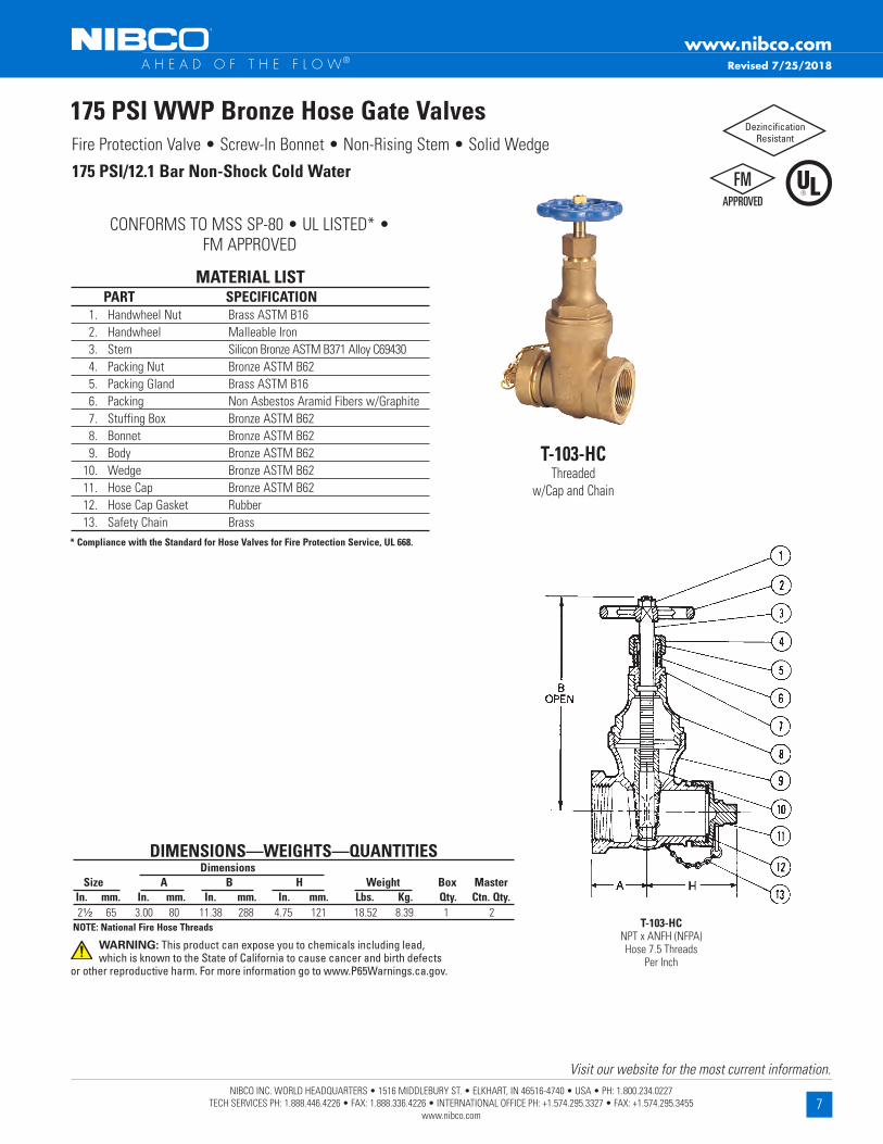
175 PSI WWP Bronze Hose Gate ValvesFire Protection Valve • Screw-In Bonnet • Non-Rising Stem • Solid Wedge
MATERIAL LIST PART SPECIFICATION 1 . Handwheel Nut Brass ASTM B16 2 . Handwheel Malleable Iron 3 . Stem Silicon Bronze ASTM B371 Alloy C69430 4 . Packing Nut Bronze ASTM B62 5 . Packing Gland Brass ASTM B16 6 . Packing Non Asbestos Aramid Fibers w/Graphite 7 . Stuffing Box Bronze ASTM B62 8 . Bonnet Bronze ASTM B62 9 . Body Bronze ASTM B62 10 . Wedge Bronze ASTM B62 11 . Hose Cap Bronze ASTM B62 12 . Hose Cap Gasket Rubber 13 . Safety Chain Brass
175 PSI/12 .1 Bar Non-Shock Cold Water
CONFORMS TO MSS SP-80 • UL LISTED* • FM APPROVED
DIMENSIONS—WEIGHTS—QUANTITIES Dimensions Size A B H Weight Box Master In . mm . In . mm . In . mm . In . mm . Lbs . Kg . Qty . Ctn . Qty . 2¹⁄₂ 65 3 .00 80 11 .38 288 4 .75 121 18 .52 8 .39 1 2NOTE: National Fire Hose Threads
T-103-HCThreaded
w/Cap and Chain
T-103-HC NPT x ANFH (NFPA) Hose 7 .5 Threads
Per Inch
* Compliance with the Standard for Hose Valves for Fire Protection Service, UL 668 .
Revised 7/25/2018
Dezincification Resistant
WARNING: This product can expose you to chemicals including lead, which is known to the State of California to cause cancer and birth defects
or other reproductive harm. For more information go to www.P65Warnings.ca.gov.

8NIBCO INC. WORLD HEADQUARTERS • 1516 MIDDLEBURY ST. • ELKHART, IN 46516-4740 • USA • PH: 1.800.234.0227
TECH SERVICES PH: 1.888.446.4226 • FAX: 1.888.336.4226 • INTERNATIONAL OFFICE PH: +1.574.295.3327 • FAX: +1.574.295.3455 www.nibco.com
Visit our website for the most current information.
www.nibco.com A H E A D O F T H E F L O W®
300 PSI WWP Bronze Hose Angle ValvesFire Protection Valve • Rising Stem • Renewable Disc • Screw-in Bonnet
MATERIAL LIST PART SPECIFICATION 1 . Handwheel Nut Brass ASTM B16 2 . Handwheel Malleable Iron 3 . Stem Silicon Bronze ASTM B371 Alloy C69430 4 . Packing Nut Bronze ASTM B62 5 . Packing Gland Bronze ASTM B16 or ASTM B62 6 . Packing Non Asbestos Aramid Fibers w/Graphite 7 . Bonnet Bronze ASTM B62 8 . Body Bronze ASTM B62 9 . Disc Holder Nut Bronze ASTM B62 10 . Drive Screw 18-8SS or Silicon Bronze ASTM B 411 Alloy C64700 11 . Disc Holder Bronze ASTM B62 12 . Hose Cap Bronze ASTM B62 13 . Seat Disc Rubber 14 . Hose Cap Gasket Rubber 15 . Safety Chain Brass 16 . Seat Disc Nut Bronze ASTM B62 17 . Cotter Key Brass
300 PSI/20 .7 Bar Non-Shock Cold Water
CONFORMS TO MSS SP-80 • UL LISTED* • FM APPROVED
DIMENSIONS—WEIGHTS—QUANTITIES Dimensions Size B H J Weight Box Master In . mm . In . mm . In . mm . In . mm . Lbs . Kg . Qty . Ctn . Qty . 2¹⁄₂ 65 10 .50 267 5 .13 130 3 .06 78 15 .61 7 .08 1 4
NOTE: National Fire Hose Threads
T-331-HCThreaded
w/Cap and Chain
T-331-HC NPT x ANFH (NFPA) Hose 7 .5 Threads
Per Inch
* Compliance with the Standard for Hose Valves for Fire Protection Service, UL 668 .
Revised 7/25/2018
Dezincification Resistant
WARNING: This product can expose you to chemicals including lead, which is known to the State of California to cause cancer and birth defects
or other reproductive harm. For more information go to www.P65Warnings.ca.gov.

9NIBCO INC. WORLD HEADQUARTERS • 1516 MIDDLEBURY ST. • ELKHART, IN 46516-4740 • USA • PH: 1.800.234.0227
TECH SERVICES PH: 1.888.446.4226 • FAX: 1.888.336.4226 • INTERNATIONAL OFFICE PH: +1.574.295.3327 • FAX: +1.574.295.3455 www.nibco.com
Visit our website for the most current information.
www.nibco.com A H E A D O F T H E F L O W®
175 PSI WWP Bronze Globe ValvesFire Protection Valve • Threaded Ends • Rubber Disc • Screw Over Bonnet
MATERIAL LIST PART SPECIFICATION 1 . Handwheel Aluminum 2 . Handwheel Screw Carbon Steel Stainless Steel (1") 3 . Stem Bronze ASTM B584 Alloy C84400 or ASTM B505 Alloy C84400 4 . Packing Nut Bronze ASTM B584 Alloy C83600 or ASTM B16 5 . Packing Graphite Impregnated (Non Asbestos) 6 . Bonnet Bronze ASTM B584 Alloy C84400 7 . Body Bronze ASTM B584 Alloy C84400 8 . Seat Disc EPDM Rubber (1/4" - 3/8") Nitrile (1/2" - 1") 9 . Seat Screw Stainless Steel 10 . Pack Washer Sheet Brass
175 PSI/12 .1 Bar Non-Shock Cold Water
UL LISTED*
DIMENSIONS—WEIGHTS—QUANTITIES Dimensions
Size A B Weight Box Master In . mm . In . mm . In . mm . Lbs . Kg . Qty . Ctn . Qty .†¹⁄₄ 8 2 .00 50 2 .75 70 .48 .22 10 100† ³⁄₈ 10 2 .00 50 2 .75 70 .45 .20 10 100¹⁄₂ 15 2 .28 58 3 .12 79 .68 .31 10 60 ³⁄₄ 20 2 .28 58 3 .12 79 .74 .34 10 60 1 25 3 .12 79 4 .50 114 1 .68 .76 5 25* UL Listed for Trim and Drain use (Subject 258) – sizes ½", ¾" , 1" . Size ¼" and 3∕8" supplied as KT-65 (Not UL Listed) . Subject to AHJ Approval .
† NOTE: See KT-211-W-UL for 1 ¼" -2" sizes .
KT-65-ULThreaded
KT-65-UL NPT x NPT
Revised 7/25/2018
Dezincification Resistant
WARNING: This product can expose you to chemicals including lead, which is known to the State of California to cause cancer and birth defects
or other reproductive harm. For more information go to www.P65Warnings.ca.gov.

10NIBCO INC. WORLD HEADQUARTERS • 1516 MIDDLEBURY ST. • ELKHART, IN 46516-4740 • USA • PH: 1.800.234.0227
TECH SERVICES PH: 1.888.446.4226 • FAX: 1.888.336.4226 • INTERNATIONAL OFFICE PH: +1.574.295.3327 • FAX: +1.574.295.3455 www.nibco.com
Visit our website for the most current information.
www.nibco.com A H E A D O F T H E F L O W®
175 PSI WWP Bronze Globe ValvesFire Protection Valve • Screw-In Bonnet • Integral Seat • Renewable Disc
MATERIAL LIST PART SPECIFICATION 1 . Handwheel Nut 300 Series Stainless Steel 2 . Identification Plate Aluminum 3 . Handwheel Aluminum Commercial Alloy 380 4 . Stem Silicon Bronze ASTM B371 Alloy C69430 Bronze ASTM B62 5 . Packing Gland or ASTM B584 Alloy C84400 or ASTM B282 or ASTM B16 6 . Packing Nut Bronze ASTM B62 or ASTM B584 Alloy C84400 or ASTM B16 7 . Packing Non Asbestos Aramid Fibers w/Graphite 8 . Bonnet Bronze ASTM B62 9 . Disc Holder Nut Bronze ASTM B140 Alloy C31400 or B62 10 . Disc Holder Bronze ASTM B62‡/ ASTM B 9 Alloy C65100 w/SS Washer 11 . Seat Disc Nitrile (W) (11/4" - 2") PTFE (Y) (21/2" - 3")
‡12 . Disc Nut Bronze ASTM B62/ASTM 89 Alloy C65100 w/SS Washer 13 . Body Bronze ASTM B62‡ 2½" and 3" size only .
175 PSI/12 .1 Bar Non-Shock Cold Water
CONFORMS TO MSS SP-80 • UL LISTED*
DIMENSIONS—WEIGHTS—QUANTITIES Dimensions Size A B Weight Box Master In . mm . In . mm . In . mm . Lbs . Kg . Qty . Ctn . Qty . 1¹⁄₄ 32 4 .31 110 6 .13 156 3 .55 1 .61 2 10 1¹⁄₂ 40 4 .69 119 7 .19 183 5 .50 2 .49 2 10 2 50 5 .63 143 7 .94 202 8 .25 3 .75 2 6 **2¹⁄₂ 65 6 .63 168 10 .19 259 15 .40 7 .00 1 2 **3 80 7 .75 197 11 .19 284 22 .44 10 .20 1 2* UL Listed for Trim and Drain use (Subject 258) – sizes 1¼", 1½", 2" . ** Sizes 2½" and 3" supplied as T-211-Y with PTFE seat disc . Subject to AHJ Approval .NOTE: See KT-65-UL for ½"-1" sizes .
KT-211-W-ULThreaded
KT-211-W-UL NPT x NPT
Dezincification Resistant
Revised 11/15/2019
WARNING: This product can expose you to chemicals including lead, which is known to the State of California to cause cancer and birth defects
or other reproductive harm. For more information go to www.P65Warnings.ca.gov.
11NIBCO INC. WORLD HEADQUARTERS • 1516 MIDDLEBURY ST. • ELKHART, IN 46516-4740 • USA • PH: 1.800.234.0227
TECH SERVICES PH: 1.888.446.4226 • FAX: 1.888.336.4226 • INTERNATIONAL OFFICE PH: +1.574.295.3327 • FAX: +1.574.295.3455 www.nibco.com
Visit our website for the most current information.
www.nibco.com A H E A D O F T H E F L O W®
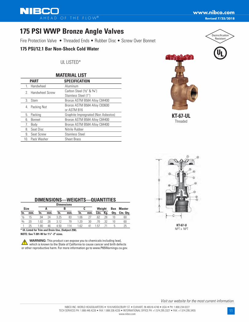
175 PSI WWP Bronze Angle ValvesFire Protection Valve • Threaded Ends • Rubber Disc • Screw Over Bonnet
MATERIAL LIST PART SPECIFICATION 1 . Handwheel Aluminum 2 . Handwheel Screw Carbon Steel (¹⁄₂" & ³⁄₄") Stainless Steel (1") 3 . Stem Bronze ASTM B584 Alloy C84400 4 . Packing Nut Bronze ASTM B584 Alloy C83600 or ASTM B16 5 . Packing Graphite Impregnated (Non Asbestos) 6 . Bonnet Bronze ASTM B584 Alloy C84400 7 . Body Bronze ASTM B584 Alloy C84400 8 . Seat Disc Nitrile Rubber 9 . Seat Screw Stainless Steel 10 . Pack Washer Sheet Brass
175 PSI/12 .1 Bar Non-Shock Cold Water
UL LISTED*
DIMENSIONS—WEIGHTS—QUANTITIES Dimensions Size A B C Weight Box Master In . mm . In . mm . In . mm . In . mm . Lbs . Kg . Qty . Ctn . Qty .¹⁄₂ 15 .94 24 3 .25 83 1 .06 27 .62 .28 10 60³⁄₄ 20 1 .02 26 3 .12 79 1 .20 30 .70 .32 10 60 1 25 1 .80 46 4 .50 114 1 .62 41 1 .57 .71 5 25* UL Listed for Trim and Drain Use, (Subject 258) .NOTE: See T-301-W for 1¹⁄4" -2" sizes .
KT-67-ULThreaded
KT-67-U NPT x NPT
Dezincification Resistant
Revised 7/25/2018
WARNING: This product can expose you to chemicals including lead, which is known to the State of California to cause cancer and birth defects
or other reproductive harm. For more information go to www.P65Warnings.ca.gov.

12NIBCO INC. WORLD HEADQUARTERS • 1516 MIDDLEBURY ST. • ELKHART, IN 46516-4740 • USA • PH: 1.800.234.0227
TECH SERVICES PH: 1.888.446.4226 • FAX: 1.888.336.4226 • INTERNATIONAL OFFICE PH: +1.574.295.3327 • FAX: +1.574.295.3455 www.nibco.com
Visit our website for the most current information.
www.nibco.com A H E A D O F T H E F L O W®
175 PSI WWP Bronze Angle ValvesFire Protection Valve • Screw-in Bonnet • Integral Seat • Renewable Disc
MATERIAL LIST PART SPECIFICATION 1 . Handwheel Nut 300 Series Stainless Steel 2 . Identification Plate Aluminum 3 . Handwheel Aluminum Commercial Alloy C38000 4 . Stem Silicon Bronze ASTM B371 Alloy C69430 5 . Packing Gland Bronze ASTM B62/ ASTM B16†/ ASTM B584 Alloy C84400 6 . Packing Nut Bronze ASTM B62/ ASTM B584 Alloy C84400/ASTM B16 7 . Packing Non Asbestos Aramid Fibers w/Graphite 8 . Bonnet Bronze ASTM B62 Alloy C83600 9 . Disc Holder Nut Bronze ASTM B62 Alloy C83600 10 . Disc Holder Bronze ASTM B62 Alloy C83600 11 . Seat Disc Nitrile (W) (11/4" - 2") PTFE (Y) (21/2" - 3") 12 . Seat Disc Nut Bronze ASTM B62‡/ ASTM B96 Alloy C65100 w/SS Washer 13 . Body Bronze ASTM B62/B584 Alloy C83600‡ 2½" and 3" size only . † Not on 2"
175 PSI/12 .1 Bar Non-Shock Cold Water
CONFORMS TO MSS SP-80 • UL/ULC LISTED*
DIMENSIONS—WEIGHTS—QUANTITIES Dimensions Size A B H Weight Box Master In . mm . In . mm . In . mm . In . mm . Lbs . Kg . Qty . Ctn . Qty . 1¹⁄₄ 32 2 .19 56 6 .13 156 2 .19 56 3 .71 1 .69 1 10 1¹⁄₂ 40 2 .38 60 7 .19 183 2 .38 60 5 .54 2 .52 1 10 2 50 2 .25 57 7 .25 184 2 .25 57 6 .72 3 .05 1 10 **2¹⁄₂ 65 3 .19 81 10 .56 268 3 .19 81 16 .13 7 .33 1 2 **3 80 3 .88 86 11 .13 283 3 .88 86 21 .72 9 .87 1 2
* UL/ULC Listed for sizes for trim and drain use (Subject 258) - Sizes 1¼", 1½", 2" .** Sizes 2½" and 3" supplied as T-311-Y with PTFE seat disc . Subject to AHJ Approval .NOTE: See KT-67-UL for ½"-1" sizes .
T-301-WThreaded
T-301-W NPT x NPT
Dezincification Resistant
Revised 7/25/2018
C
WARNING: This product can expose you to chemicals including lead, which is known to the State of California to cause cancer and birth defects
or other reproductive harm. For more information go to www.P65Warnings.ca.gov.
13NIBCO INC. WORLD HEADQUARTERS • 1516 MIDDLEBURY ST. • ELKHART, IN 46516-4740 • USA • PH: 1.800.234.0227
TECH SERVICES PH: 1.888.446.4226 • FAX: 1.888.336.4226 • INTERNATIONAL OFFICE PH: +1.574.295.3327 • FAX: +1.574.295.3455 www.nibco.com
Visit our website for the most current information.
www.nibco.com A H E A D O F T H E F L O W®
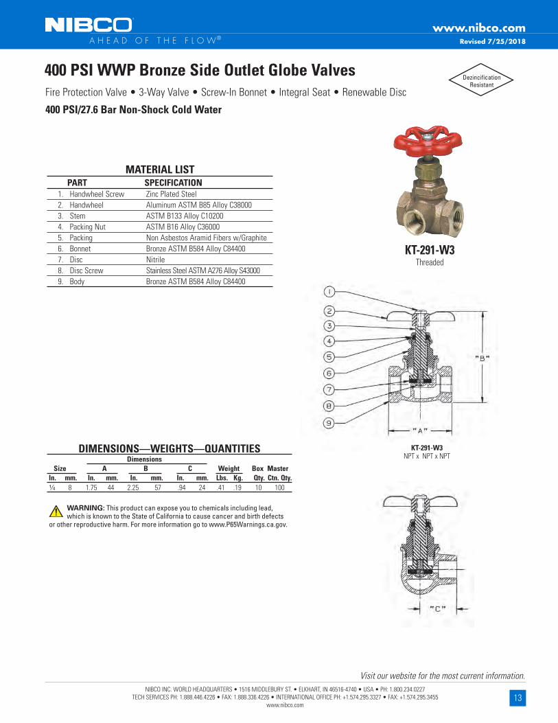
400 PSI WWP Bronze Side Outlet Globe ValvesFire Protection Valve • 3-Way Valve • Screw-In Bonnet • Integral Seat • Renewable Disc
MATERIAL LIST PART SPECIFICATION 1 . Handwheel Screw Zinc Plated Steel 2 . Handwheel Aluminum ASTM B85 Alloy C38000 3 . Stem ASTM B133 Alloy C10200 4 . Packing Nut ASTM B16 Alloy C36000 5 . Packing Non Asbestos Aramid Fibers w/Graphite 6 . Bonnet Bronze ASTM B584 Alloy C84400 7 . Disc Nitrile 8 . Disc Screw Stainless Steel ASTM A276 Alloy S43000 9 . Body Bronze ASTM B584 Alloy C84400
400 PSI/27 .6 Bar Non-Shock Cold Water
DIMENSIONS—WEIGHTS—QUANTITIES Dimensions Size A B C Weight Box Master In . mm . In . mm . In . mm . In . mm . Lbs . Kg . Qty . Ctn . Qty .¹⁄4 8 1 .75 44 2 .25 57 .94 24 .41 .19 10 100
KT-291-W3Threaded
KT-291-W3 NPT x NPT x NPT
Dezincification Resistant
Revised 7/25/2018
WARNING: This product can expose you to chemicals including lead, which is known to the State of California to cause cancer and birth defects
or other reproductive harm. For more information go to www.P65Warnings.ca.gov.

14NIBCO INC. WORLD HEADQUARTERS • 1516 MIDDLEBURY ST. • ELKHART, IN 46516-4740 • USA • PH: 1.800.234.0227
TECH SERVICES PH: 1.888.446.4226 • FAX: 1.888.336.4226 • INTERNATIONAL OFFICE PH: +1.574.295.3327 • FAX: +1.574.295.3455 www.nibco.com
Visit our website for the most current information.
www.nibco.com A H E A D O F T H E F L O W®
200 PSI WWP Bronze Check ValvesFire Protection Valve • Horizontal Swing • Rubber Disc
MATERIAL LIST PART SPECIFICATION 1 . Bonnet Bronze ASTM B62 or B584 Alloy C84400 2 . Body Bronze ASTM B62 or B584 Alloy C84400 3 . Hinge Pin 316 SS or 304 SS 4 . Disc Hanger Bronze ASTM B62
5 . Hanger Nut Bronze ASTM B97 Alloy C65500 or Brass ASTM B16 6 . Disc Holder Bronze ASTM B62
7 . Seat Disc Nitrile (W) PTFE (Y)‡ 8 . Seat Disc Nut Brass ASTM B16 or B97 Alloy C65500 9 . Hinge Pin Plug Bronze ASTM B140 Alloy C32000 (Not Shown)
*10 . Seat Disc Washer Stainless Steel* Sizes ¾" , 1" , 1¼" and 1½" only . No Seat Disc Washers on 1/2" and 3/4" with PTFE (Y) discs .‡ 2½" and 3" size only .
200 PSI/13 .8 Bar Non-Shock Cold Water
CONFORMS TO MSS SP-80
DIMENSIONS—WEIGHTS—QUANTITIES Dimensions Size A B Weight Box Master . In . mm . In . mm . In . mm . Lbs . Kg . Qty . Ctn . Qty .¹⁄₂ 15 2 .44 62 1 .69 43 .58 .26 10 50 3⁄₄ 20 2 .94 75 1 .88 48 .92 .42 10 50 1 25 3 .56 90 2 .31 59 1 .55 .70 5 30 1¹⁄₄ 32 4 .19 106 2 .69 68 2 .32 1 .05 5 20 1¹⁄₂ 40 4 .50 114 2 .94 75 3 .00 1 .36 2 10 2 50 5 .25 133 3 .81 97 4 .87 2 .21 2 10 2¹⁄₂ 65 8 .00 203 5 .06 129 11 .48 5 .22 1 5 3 80 9 .25 235 6 .25 159 17 .53 7 .97 1 4 Sizes 2½" and 3" supplied as T-433-Y with PTFE seat disc .
NIBCO check valves may be installed in both horizontal and vertical lines with upward flow or in any intermediate position .
WARNING - Valve must be installed downstream of receiver tank if used in line with reciprocating air compressor .
KT-403-W NPT x NPT
KT-403-WThreaded
Dezincification Resistant
Revised 9/1/2021
WARNING: This product can expose you to chemicals including lead, which is known to the State of California to cause cancer and birth defects
or other reproductive harm. For more information go to www.P65Warnings.ca.gov.

15NIBCO INC. WORLD HEADQUARTERS • 1516 MIDDLEBURY ST. • ELKHART, IN 46516-4740 • USA • PH: 1.800.234.0227
TECH SERVICES PH: 1.888.446.4226 • FAX: 1.888.336.4226 • INTERNATIONAL OFFICE PH: +1.574.295.3327 • FAX: +1.574.295.3455 www.nibco.com
Visit our website for the most current information.
www.nibco.com A H E A D O F T H E F L O W®
250 PSI WWP Bronze Ring Check® Valves Fire Protection Valve • Inline Lift Type • Rubber Discs • Spring Actuated
250 PSI/17 .2 Bar Non-Shock Cold Working Pressureu
T-480Threaded
T-480 NPT x NPT
DIMENSIONS—WEIGHTS—QUANTITIES Dimensions Size A B C T-480 Master In . mm . In . mm . In . mm . In . mm . In . mm . . Ctn . Qty . ³⁄₈ 10 2 .00 51 1 .38 35 1 .44 37 0 .41 0 .19 100 ¹⁄₂ 15 2 .06 52 1 .38 35 1 .19 30 0 .36 0 .16 100 ³⁄₄ 20 2 .25 57 1 .63 41 1 .31 33 0 .48 0 .22 100 1 25 2 .63 67 2 .00 51 1 .50 38 0 .77 0 .35 50 1 ¹⁄₄ 32 2 .94 75 2 .38 60 1 .69 43 1 .14 0 .51 30 1 ¹⁄₂ 40 3 .31 84 2 .75 70 2 .00 51 1 .63 0 .74 30 2 50 3 .69 94 3 .38 86 2 .31 59 2 .27 1 .03 10Ordering: The T-480 has standard Buna-N Discs . Also available with PTFE (Y) Discs; specify T-480-Y . 3∕8" thru 2" require ½ pound pressure to open .
NIBCO check valves may be installed in both horizontal and vertical lines with upward flow or in any intermediate position .
WARNING - Valve must be installed downstream of receiver tank if used in line with reciprocating air compressor .
Do Not Use as a Footvalve .
Warning – Do Not Use For Reciprocating Air Compressor Service .
MATERIAL LIST PART SPECIFICATION 1 . Body Bronze ASTM B584 Alloy C84400 2 . Stem Stainless Steel ASTM A582 Alloy C30300 3 . Spring 316 Stainless Steel 4 . Disc Holder Stainless Steel Type 301 5 . Disc Water, Oil or Gas (Buna-N) Steam (PTFE) (Y) 6 . Seat Screw Stainless Steel ASTM A276 Alloy S43000 7 . Body End Bronze ASTM B584 Alloy C84400
Dezincification Resistant
Revised 7/25/2018
WARNING: This product can expose you to chemicals including lead, which is known to the State of California to cause cancer and birth defects
or other reproductive harm. For more information go to www.P65Warnings.ca.gov.

16NIBCO INC. WORLD HEADQUARTERS • 1516 MIDDLEBURY ST. • ELKHART, IN 46516-4740 • USA • PH: 1.800.234.0227
TECH SERVICES PH: 1.888.446.4226 • FAX: 1.888.336.4226 • INTERNATIONAL OFFICE PH: +1.574.295.3327 • FAX: +1.574.295.3455 www.nibco.com
Visit our website for the most current information.
www.nibco.com A H E A D O F T H E F L O W®
Fire Protection Valve • Two-Piece Body • Chrome Plated Ball • Blowout-Proof Stem • Reinforced PTFE Seats • Full Port
600 PSI WWP Bronze Ball Valves
600 PSI/41 .4 Bar Non-Shock Cold Water
CONFORMS TO MSS SP-110
DIMENSIONS—WEIGHTS—QUANTITIES Dimensions Size A B C D Port Weight Box Master In . mm . In . mm . In . mm . In . mm . In . mm . Lbs . Kg . Qty . Ctn . Qty . 1⁄4 8 2 .00 51 1 .75 44 5 .00 127 .38 10 .45 .20 10 100 3⁄8 10 2 .00 51 1 .75 44 5 .00 127 .38 10 .45 .20 10 100 ¹⁄₂ 15 2 .44 62 1 .88 48 5 .19 132 .50 13 .64 .29 10 100 3⁄4 20 2 .94 75 2 .25 57 6 .25 159 .75 19 1 .33 .60 5 50 1 25 3 .34 85 2 .38 60 6 .44 164 1 .00 25 1 .79 .81 5 20 1¹⁄₄ 32 4 .19 106 3 .00 76 6 .75 171 1 .25 32 2 .17 .99 5 20 1¹⁄₂ 40 4 .72 120 3 .16 80 9 .06 230 1 .25 32 3 .27 1 .49 5 10 2 50 5 .16 131 3 .50 89 9 .25 235 2 .00 51 5 .09 2 .31 2 8
Dezincification Resistant
T-585-70Threaded
T-585-70 NPT x NPT
MATERIAL LIST PART SPECIFICATION 1 . Handle Nut Zinc Plated Steel 2 . Handle Zinc Plated Steel Clear Chromate Plastisol Coated 3 . Threaded Pack Gland Brass ASTM B16 Alloy C36000 4 . Packing PTFE 5 . Stem Silicon Bronze ASTM B371 Alloy C69430 or ASTM B99 Alloy C65100 6 . Thrust Washer Reinforced PTFE 7 . Ball Brass ASTM B124 Alloy C37700 or ASTM B16 Alloy C36000 EACH with Hard Chrome Plate 8 . Seat Ring (2) Reinforced PTFE 9 . Body Cast Red Bronze ASTM B584 Alloy C84400 10 . Body End Piece Cast Red Bronze ASTM B584 Alloy C84400¼" and 3∕8" size only has A304 stainless steel grounding washer .
Revised 7/25/2018
WARNING: This product can expose you to chemicals including lead, which is known to the State of California to cause cancer and birth defects
or other reproductive harm. For more information go to www.P65Warnings.ca.gov.

17NIBCO INC. WORLD HEADQUARTERS • 1516 MIDDLEBURY ST. • ELKHART, IN 46516-4740 • USA • PH: 1.800.234.0227
TECH SERVICES PH: 1.888.446.4226 • FAX: 1.888.336.4226 • INTERNATIONAL OFFICE PH: +1.574.295.3327 • FAX: +1.574.295.3455 www.nibco.com
Visit our website for the most current information.
www.nibco.com A H E A D O F T H E F L O W®
300 PSI WWP Bronze Ball ValvesFire Protection Valve • Two-Piece Body • Chrome Plated Ball • Blowout-Proof Stem • Reinforced PTFE Seats
MATERIAL LIST PART SPECIFICATION 1 . Handle Nut Zinc Plated Steel 2 . Handle Zinc Plated Steel Clear Chromate with Plastisol Grip 3 . Threaded Pack Gland Brass ASTM B16 4 . Packing PTFE 5 . Stem Silicon Bronze ASTM B371 Alloy C69430 or ASTM B99 Alloy C65100 6 . Thrust Washer Reinforced PTFE 7 . Ball Brass ASTM B124 Alloy C37700 or ASTM B16 Alloy C36000 with Hard Chrome Plate 8 . Seat Ring (2) Reinforced PTFE 9 . Body Cast Red Bronze ASTM B584 Alloy C84400 10 . Body End Piece Cast Red Bronze ASTM B584 Alloy C84400¼" and 3∕8" size only has A304 stainless steel grounding washer .
300 PSI/20 .7 Bar Non-Shock Cold Water
CONFORMS TO MSS SP-110 • UL LISTED† • FM APPROVED†
DIMENSIONS—WEIGHTS—QUANTITIES KT-585-70-UL Dimensions Size A B C D Port Weight Box Master In . mm . In . mm . In . mm . In . mm . In . mm . Lbs . Kg . Qty . Ctn . Qty . ¹⁄₄ 8 2 .00 51 1 .75 44 5 .00 127 .38 10 .45 .20 10 100 ³⁄₈ 10 2 .00 51 1 .75 44 5 .00 127 .38 10 .45 .20 10 100 ¹⁄₂ 15 2 .44 62 1 .88 48 5 .19 132 .50 13 .64 .29 10 100 ³⁄4 20 2 .94 75 2 .25 57 6 .25 159 .75 19 1 .33 .60 5 50 1 25 3 .34 85 2 .38 59 6 .44 164 1 .00 25 1 .79 .81 5 20 KT-580-70-UL Dimensions Size A B C D Port Weight Box Master In . mm . In . mm . In . mm . In . mm . In . mm . Lbs . Kg . Qty . Ctn . Qty . 1 ¹⁄₄ 32 3 .94 100 2 .63 67 6 .75 171 1 .00 25 2 .17 .99 5 20 1 ¹⁄₂ 40 4 .31 110 3 .00 76 8 .91 228 1 .25 32 3 .27 1 .49 5 20 2 50 4 .63 117 3 .25 83 9 .06 230 1 .50 38 5 .09 2 .31 5 10 *2 ¹⁄₂ 65 5 .84 148 3 .53 90 9 .66 245 2 .00 51 8 .25 3 .79 2 6 *3 80 7 .09 202 4 .41 112 11 .53 293 2 .50 64 15 .65 7 .11 1 4
† UL Listed, FM Approved for trim and drain use (UL Subject 258) – 585-70-UL ¼" thru 1" – 580-70-UL 1¼" thru 2" .*2½-3" supplied as T-580-70-UL subject to AHJ approval .DO NOT USE FOR NATURAL GAS
KT-585-70-UL Full Port
NPT x NPT
KT-580-70-UL Standard Port
NPT x NPT
KT-585-70-UL¹⁄₄" - 1" Full Port
Threaded
KT-580-70-UL1¹⁄₄" - 2" Standard Port
Threaded
Dezincification Resistant
Revised 7/25/2018
WARNING: This product can expose you to chemicals including lead, which is known to the State of California to cause cancer and birth defects
or other reproductive harm. For more information go to www.P65Warnings.ca.gov.
18NIBCO INC. WORLD HEADQUARTERS • 1516 MIDDLEBURY ST. • ELKHART, IN 46516-4740 • USA • PH: 1.800.234.0227
TECH SERVICES PH: 1.888.446.4226 • FAX: 1.888.336.4226 • INTERNATIONAL OFFICE PH: +1.574.295.3327 • FAX: +1.574.295.3455 www.nibco.com
Visit our website for the most current information.
www.nibco.com A H E A D O F T H E F L O W®
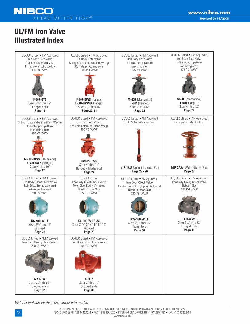
UL/FM Iron ValveIllustrated Index
Revised 5/19/2021
UL/ULC Listed • FM ApprovedGate Valve Indicator Post
NIP-2AW Wall Indicator PostPage 27
UL/ULC ListedIron Body Silent Check ValveTwin Disc, Spring Actuated
Nitrile Rubber Seat350 PSI WWP
KG-900-W-LF 350Sizes 21/2", 3", 4", 6", 8", 10"
GroovedPage 29
UL/ULC Listed • FM ApprovedIron Body Silent Check ValveTwin Disc, Spring Actuated
Nitrile Rubber Seat250 PSI WWP
KG-900-W-LFSizes 21/2" thru 12"
GroovedPage 28
UL/ULC Listed • FM ApprovedGate Valve Indicator Post
NIP-1AU Upright Indicator PostPage 25 - 26
UL/ULC Listed • FM ApprovedDI Body Gate Valve
Non-rising stem, resilient wedge300 PSI WWP
FM609-RWSSizes 4" thru 12"
Flanged x MechanicalPage 24
UL/ULC Listed • FM ApprovedDI Body Gate Valve (Resilient Wedge)
Indicator post patternNon-rising stem300 PSI WWP
M-609-RWS (Mechanical)F-609-RWS (Flanged)
Sizes 4" thru 16"Page 23
UL/ULC Listed • FM ApprovedIron Body Check Valve
Double-Door Style, Spring ActuatedNitrile Rubber Seat
250 PSI WWP
KW-900-W-LFSizes 21/2" thru 16"
Wafer StylePage 30
UL/ULC Listed • FM ApprovedIron Body Swing Check Valve
Rubber Disc175 PSI WWP
F-908-WSizes 21/2" thru 12"
Flanged endsPage 31
UL/ULC Listed • FM ApprovedIron Body Swing Check Valve
250 PSI WWP
G-917-WSizes 21/2" thru 6"
Grooved endsPage 32
UL/ULC Listed • FM ApprovedIron Body Gate Valve
Outside screw and yokeRising stem, solid wedge
175 PSI WWP
F-607-OTSSizes 21/2" thru 12"
Flanged endsPage 19
UL/ULC Listed • FM ApprovedDI Body Gate Valve
Rising stem, solid resilient wedgeOutside screw and yoke
300 PSI WWP
F-607-RWS (Flanged)F-607-RWSB (Flanged)
Sizes 21/2" thru 16"Page 20, 21
UL/ULC Listed • FM ApprovedIron Body Gate ValveIndicator post pattern
non-rising stem175 PSI WWP
M-609 (Mechanical)F-609 (Flanged)Sizes 4" thru 12"
Page 22
UL/ULC Listed • FM ApprovedIron Body Swing Check Valve
300 PSI WWP
G-997Sizes 2" thru 12"
Grooved endsPage 33
UL/ULC Listed • FM ApprovedIron Body Gate ValveIndicator post pattern
non-rising stem175 PSI WWP
M-609 (Mechanical)F-609 (Flanged)Sizes 4" thru 12"
Page 22

19NIBCO INC. WORLD HEADQUARTERS • 1516 MIDDLEBURY ST. • ELKHART, IN 46516-4740 • USA • PH: 1.800.234.0227
TECH SERVICES PH: 1.888.446.4226 • FAX: 1.888.336.4226 • INTERNATIONAL OFFICE PH: +1.574.295.3327 • FAX: +1.574.295.3455 www.nibco.com
Visit our website for the most current information.
www.nibco.com A H E A D O F T H E F L O W® Revised 6/24/2021
WARNING: This product can expose you to chemicals including lead, which is known to the State of California to cause cancer and birth defects
or other reproductive harm. For more information go to www.P65Warnings.ca.gov.
175 PSI WWP Iron Body Gate ValvesFire Protection Valve • Bolted Bonnet • Outside Screw and Yoke • Solid Wedge • Pre-Grooved Stem for Supervisory Switch Mounting
MATERIAL LIST PART SPECIFICATION 1 . Stem Copper Alloy, ASTM B16 C36000 2 . Nut, Handwheel Cast Copper Alloy, ASTM B584 C84400 3 . Handwheel, Orange Cast Iron, ASTM A126-B 4 . Bushing, Yoke Cast Copper Alloy, ASTM B584 C84400 5 . Screw, Hex - Bonnet Cap Steel, ASTM A307 / SAE J429 6 . Cap, Bonnet Ductile Iron ASTM A536 7 . Nut, Square - Bonnet Cap Steel, ASTM A563 8 . Bonnet1 Cast Iron, ASTM A126-B 9 . Nut, Heavy Hex - Gld Follow Steel, ASTM A563 10 . Gland Follower Ductile Iron ASTM A536 11 . Pack Gland Powdered Metal ASTM B783 12 . Pack Ring Aramid Fiber / Graphite 13 . Bolt, Sq Head - Gld Follow Steel, ASTM A307 / SAE J429 14 . Screw, Hex - Body Steel, ASTM A307 / SAE J429 15 . Gasket, Body Synthetic Fiber / Nitrile 16 . Nut, Hex - Body Steel, ASTM A563 17 . Collar, Stem Copper Alloy, ASTM B16 C36000 18 . Pin, Wedge Copper Alloy, ASTM B140 C31600 19 . Ring, Seat - Wedge Cast Copper Alloy, ASTM B584 C84400 20 . Wedge2 Cast Iron, ASTM A126-B 21 . Ring, Seat - Body Cast Copper Alloy, ASTM B584 C84400 22 . Body Cast Iron, ASTM A126-B1 Sizes thru 8", Yoke and Bonnet are intergral . 10" and 12" sizes separate Yoke is bolted to Bonnet .2 Sizes 2½" thru 6" have Cast Copper Alloy Wedges . Sizes 8" thru 12" made with Cast Iron Wedge with Cast Copper Alloy Face Rings .TS: Pre-grooved Stem for Supervisory Switch Activation .NOTE: 1.Valve Flanges per ASME B16.1, Class 125 2. NIBCO may substitute Ductile Iron ASTM A395 (60-40-18) for ASTM A126 Class B Cast Iron for
the Body, Bonnet, Wedge, or Disc. NIBCO may substitute Ductile Iron ASTM A395 (60-40-18) or ASTM A536 (65-45-12) for all other ASTM A126 Class B Cast Iron components.
175 PSI/12 .1 Bar Non-Shock Cold Water
CONFORMS TO MSS SP-70 • UL/ULC LISTED* • FM APPROVED •
APPROVED BY THE NEW YORK CITY B .S .A . 143-69-SA
DIMENSIONS—WEIGHTS—QUANTITIES Dimensions Size A B C D E Weight In . mm . In . mm . In . mm . In . mm . In . mm . In . mm . Lbs . Kg .21/2 65 7 .50 191 17 .26 438 8 .00 203 7 .00 178 0 .69 18 55 25 3 80 8 .00 203 19 .44 494 8 .00 203 7 .50 191 0 .75 19 67 30 4 100 9 .00 229 23 .54 598 10 .25 260 9 .00 229 0 .94 24 107 49 5 125 10 .00 254 27 .01 686 10 .25 260 10 .00 254 0 .94 24 145 66 6 150 10 .50 267 30 .73 781 12 .00 305 11 .00 279 1 .00 25 178 81 8 200 11 .50 292 40 .29 1023 14 .00 356 13 .50 343 1 .12 28 309 140 10 250 13 .00 330 48 .45 1231 16 .25 413 16 .00 406 1 .19 30 481 219 12 300 14 .00 356 56 .26 1429 18 .00 457 19 .00 483 1 .25 32 706 321
F-607-OTS
Flg x Flg
F-607-OTSFlanged
FREEZING WEATHER PRECAUTION: Subsequent to testing a piping system, gate valve should be in an open position to allow complete drainage .
* Compliance with the Standard for Gate Valves for Fire Protection Service, UL 262, and the Canadian Requirements .

20NIBCO INC. WORLD HEADQUARTERS • 1516 MIDDLEBURY ST. • ELKHART, IN 46516-4740 • USA • PH: 1.800.234.0227
TECH SERVICES PH: 1.888.446.4226 • FAX: 1.888.336.4226 • INTERNATIONAL OFFICE PH: +1.574.295.3327 • FAX: +1.574.295.3455 www.nibco.com
Visit our website for the most current information.
www.nibco.com A H E A D O F T H E F L O W®
300 PSI CWP Iron Body Gate ValvesFire Protection Valve • Outside Screw and Yoke • Resilient Wedge • Epoxy Coated Interior/Exterior • Pre-Grooved Stem for Supervisory Switch • Drilled, Tapped and Plugged at Boss Location A**
300 PSI/20 .6 Bar Non-Shock Cold Working Pressure
F-607-RWSFlanged
UL/ULC LISTED† • FM APPROVED • CERTIFIED LEAD-FREE BY TRUESDAIL LABORATORIES TO NSF/ANSI 61 & 372
Coating — Electrostatically applied fusion-bonded epoxy 8-20 mil . inside and outside meets or exceeds AWWA C550 . ** Drilled, tapped and plugged at Position A with ½" valve sizes 2½"–4", ¾" on 6"–8", 1" on 10"–16" .† Compliance with the Standard for Gate Valves for Fire Protection Service, UL 262, and the Canadian Requirements, ULC/ORD-C262 .NOTE: Flanged valve is consistent with ANSI B16 .1 Class 125 .
FREEZING WEATHER PRECAUTION: Subsequent to testing a piping system, gate valve should be in an open position to allow complete drainage .LEAD-FREE: Weighted average lead content <0.25%
Revised 11/15/2021
WARNING: This product can expose you to chemicals including lead, which is known to the State of California to cause cancer and birth defects or other reproductive harm. For more information go to www.P65Warnings.ca.gov.
*14 and 16" valves 250 PSI CWP
DIMENSIONS—WEIGHTS—QUANTITIESDimensions
Size A B Open B Closed C D E F G Bolt Circle Flange Holes .
Turns to Open .
WeightIn . mm . In . mm . In . mm . In . mm . In . mm . In . mm . In . mm . In . mm . In . mm . In . mm . Lbs . Kg .2¹⁄₂ 65 7.5 190 17.2 437 14.5 368 0.69 17.5 7.0 178 7.9 200 1.48 38 1.4 36 5.50 140 4 6.30 39 183 80 8.0 203 18.6 472 15.4 391 0.75 19.0 7.5 191 7.9 200 1.73 44 1.4 36 6.00 152 4 10.00 44 204 100 9.0 229 21.4 544 17.3 439 0.94 24.0 9.0 229 10.2 260 2.13 54 1.4 36 7.50 191 8 10.00 72 336 150 10.5 267 28.4 721 22.4 569 1.00 25.4 11.0 279 12.4 315 2.26 57 1.5 39 9.50 241 8 15.00 117 538 200 11.5 292 36.1 917 28.0 711 1.13 28.7 13.5 343 14.8 375 2.46 63 1.5 39 11.75 298 8 16.70 198 9010 250 13.0 330 44.5 1130 34.4 874 1.19 30.2 16.0 406 16.4 416 3.15 80 1.8 46 14.25 362 12 20.80 374 17012 300 14.0 356 51.7 1313 39.7 1008 1.25 31.8 19.0 483 17.5 445 2.91 74 1.8 46 17.00 432 12 25.00 493 22414* 350 15.0 381 62.8 1595 50.0 1270 1.38 35.0 21.0 533 19.7 500 2.95 75 3.2 81 18.75 476 12 43.80 620 28416* 400 16 .0 406 66 .5 1689 50 .7 1288 1 .44 37 .0 23 .5 597 19 .7 500 3 .03 77 3 .2 81 21 .25 540 16 50 .00 816 370
Position A
F-607-RWS Flg x Flg
MATERIAL LISTPART SPECIFICATION
1 . Valve Body Ductile Iron ASTM A5362 . Resilient Wedge Ductile Iron ASTM A536/EPDM ASTM D2000
3 . Wedge Nut ASTM B584 UNS C836004 . Dowel Pin ASTM A276 SS3045 . Stem Back Seat O-Ring EPDM ASTM D20006 . Bonnet Gasket EPDM ASTM D20007 . Bonnet Ductile Iron ASTM A5368 . Stem Packing EPDM ASTM D20009 . Threaded Rod ASTM A276 SS304
10 . Gland Bushing ASTM B584 UNS C8360011 . Gland Ductile Iron ASTM A53612 . Gland Nut ASTM B148 C95200 Aluminum Bronze13 . Yoke Ductile Iron ASTM A53614 . Yoke Bushing ASTM B150 C6140015 . Flat Point Set Screw ASTM F912M16 . Yoke Bushing Retainer Cast Iron ASTM A126 Class B17 . Handwheel Ductile Iron ASTM A53618 . Handwheel Nut Carbon Steel Corrosion Resistant19 . Stem Stainless Steel 30420 . Bonnet Screw Corrosion-resistant Steel21 . NPT Pipe Plug Steel ASME B16 .1422 . UL/FM Label (not shown) Aluminum23 . Yoke Screw Steel Plated ASTM A30724 . Drive Screw Label (not shown) Stainless Steel 304

21NIBCO INC. WORLD HEADQUARTERS • 1516 MIDDLEBURY ST. • ELKHART, IN 46516-4740 • USA • PH: 1.800.234.0227
TECH SERVICES PH: 1.888.446.4226 • FAX: 1.888.336.4226 • INTERNATIONAL OFFICE PH: +1.574.295.3327 • FAX: +1.574.295.3455 www.nibco.com
Visit our website for the most current information.
www.nibco.com A H E A D O F T H E F L O W®
300 PSI CWP Iron Body Gate ValvesFire Protection Valve • Outside Screw and Yoke • Resilient Wedge • Epoxy Coated Interior/Exterior • Pre-Grooved Stem for Supervisory Switch • Boss Position A Not Tapped
300 PSI/20 .6 Bar Non-Shock Cold Working Pressure
F-607-RWSBFlanged
UL/ULC LISTED† • FM APPROVED • CERTIFIED LEAD-FREE BY TRUESDAIL LABORATORIES TO NSF/ANSI 61 & 372
Coating — Electrostatically applied fusion-bonded epoxy 8-20 mil . inside and outside meets or exceeds AWWA C550 . † Compliance with the Standard for Gate Valves for Fire Protection Service, UL 262, and the Canadian Requirements, ULC/ORD-C262 .NOTE: Flanged valve is consistent with ANSI B16 .1 Class 125 .
FREEZING WEATHER PRECAUTION: Subsequent to testing a piping system, gate valve should be in an open position to allow complete drainage .LEAD-FREE: Weighted average lead content <0.25%
Revised 11/15/2021
WARNING: This product can expose you to chemicals including lead, which is known to the State of California to cause cancer and birth defects or other reproductive harm. For more information go to www.P65Warnings.ca.gov.
*14 and 16" valves 250 PSI CWP
DIMENSIONS—WEIGHTS—QUANTITIESDimensions
Size A B Open B Closed C D E F G Bolt Circle Flange Holes .
Turns to Open .
WeightIn . mm . In . mm . In . mm . In . mm . In . mm . In . mm . In . mm . In . mm . In . mm . In . mm . Lbs . Kg .2¹⁄₂ 65 7.5 190 17.8 453 14.9 378 0.69 17.5 7.0 178 7.9 200 1.50 38 1.42 36 5.50 140 4 6.3 39 183 80 8.0 203 19.7 500 15.9 405 0.75 19.0 7.5 191 7.9 200 1.73 44 1.42 36 6.00 152 4 10.0 44 204 100 9.0 229 21.0 534 16.6 422 0.94 24.0 9.0 229 10.2 260 2.13 54 1.42 36 7.50 191 8 10.0 72 336 150 10.5 267 29.3 744 22.9 581 1.00 25.4 11.0 279 12.4 315 2.24 57 1.54 39 9.50 241 8 15.0 117 538 200 11.5 292 37.0 939 28.5 724 1.13 28.6 13.5 343 14.8 375 2.48 63 1.54 39 11.75 298 8 16.7 198 9010 250 13.0 330 44.8 1139 34.5 877 1.19 30.2 16.0 406 16.4 416 3.15 80 1.82 46 14.25 362 12 20.8 374 17012 300 14.0 356 52.2 1326 39.9 1014 1.25 31.8 19.0 483 17.5 445 2.91 74 1.82 46 17.00 432 12 25.0 493 22414* 350 15.0 375 62.2 1580 50.0 1270 1.38 35.0 21.0 533 19.7 500 2.95 75 3.20 81 18.75 476 12 43.8 620 28416* 400 16 .0 400 65 .9 1674 50 .4 1280 1 .44 37 .0 23 .5 597 19 .7 500 3 .03 77 3 .20 81 21 .25 540 16 50 .0 816 370
F-607-RWSB Flg x Flg
MATERIAL LISTPART SPECIFICATION
1 . Valve Body Ductile Iron ASTM A5362 . Resilient Wedge Ductile Iron ASTM A536/EPDM ASTM D2000
3 . Wedge Nut ASTM B584 UNS C836004 . Dowel Pin ASTM A276 SS3045 . Stem Back Seat O-Ring EPDM ASTM D20006 . Bonnet Gasket EPDM ASTM D20007 . Bonnet Ductile Iron ASTM A5368 . Stem Packing EPDM ASTM D20009 . Threaded Rod ASTM A276 SS304
10 . Gland Bushing ASTM B584 UNS C8360011 . Gland Ductile Iron ASTM A53612 . Gland Nut ASTM B148 C95200 Aluminum Bronze13 . Yoke Ductile Iron ASTM A53614 . Yoke Bushing ASTM B150 C6140015 . Flat Point Set Screw ASTM F912M16 . Yoke Bushing Retainer Cast Iron ASTM A126 Class B17 . Handwheel Ductile Iron ASTM A53618 . Handwheel Nut Carbon Steel Zinc Plated19 . Stem Stainless Steel 30420 . Bonnet Screw Corrosion-resistant Steel21 . Drive Screw Label (not shown) Stainless Steel 30422 . UL/FM Label (not shown) Aluminum23 . Yoke Screw Steel Plated ASTM A307
22NIBCO INC. WORLD HEADQUARTERS • 1516 MIDDLEBURY ST. • ELKHART, IN 46516-4740 • USA • PH: 1.800.234.0227
TECH SERVICES PH: 1.888.446.4226 • FAX: 1.888.336.4226 • INTERNATIONAL OFFICE PH: +1.574.295.3327 • FAX: +1.574.295.3455 www.nibco.com
Visit our website for the most current information.
www.nibco.com A H E A D O F T H E F L O W®
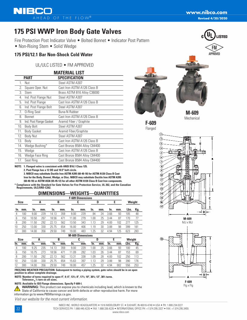
175 PSI WWP Iron Body Gate ValvesFire Protection Post Indicator Valve • Bolted Bonnet • Indicator Post Pattern • Non-Rising Stem • Solid Wedge
+-
175 PSI/12 .1 Bar Non-Shock Cold Water
UL/ULC LISTED • FM APPROVED
MATERIAL LIST PART SPECIFICATION 1 . Nut Steel ASTM A307 2 . Square Oper . Nut Cast Iron ASTM A126 Class B 3 . Stem Brass ASTM B16 Alloy C36000 4 . Ind . Post Flange Nut Steel ASTM A307 5 . Ind . Post Flange Cast Iron ASTM A126 Class B 6 . Ind . Post Flange Bolt Steel ASTM A307 7 . O-Ring Seal Buna-N Rubber 8 . Bonnet Cast Iron ASTM A126 Class B 9 . Ind . Post Flange Gasket Aramid Fiber / Graphite 10 . Body Bolt Steel ASTM A307 11 . Body Gasket Aramid Fiber/Graphite 12 . Body Nut Steel ASTM A307 13 . Body Cast Iron ASTM A126 Class B 14 . Wedge Bushing* Cast Bronze B584 Alloy C84400 15 . Wedge Cast Iron ASTM A126 Class B 16 . Wedge Face Ring Cast Bronze B584 Alloy C84400 17 . Seat Ring Cast Bronze B584 Alloy C84400
NOTE: 1. Flanged valve is consistent with ANSI B16.1 Class 125. 2. Post Flange has a 12 OD and 10.5" bolt circle. 3. NIBCO may substitute Ductile Iron ASTM A395 (60-40-18) for ASTM A126 Class B Cast
Iron for the Body, Bonnet, Wedge, or Disc. NIBCO may substitute Ductile Iron ASTM A395 (60-40-18) or ASTM A536 (65-45-12) for all other ASTM A126 Class B Cast Iron components.
M-609Mechanical
F-609Flanged
FREEZING WEATHER PRECAUTION: Subsequent to testing a piping system, gate valve should be in an open position to allow complete drainage .NOTE: Number of turns required to open 4", 9; 6", 13½; 8", 17½; 10", 30¼; 12", 38¼ turns . Tolerance ½ turn on all sizes .NOTE: Available to ISO Flange dimensions . Specify F-609-I .
M-609 MJ x MJ
F-609 Flg x Flg
DIMENSIONS—WEIGHTS—QUANTITIES F-609 Dimensions Size A B C D E Weight In . mm . In . mm . In . mm . In . mm . In . mm . In . mm . Lbs . Kg . 4 100 9 .00 229 14 .13 359 9 .00 229 .94 24 3 .66 93 105 48 6 150 10 .50 267 18 .56 471 11 .00 279 1 .00 25 3 .44 87 170 77 8 200 11 .50 292 22 .13 562 13 .50 343 1 .13 29 4 .00 102 277 125 10 250 13 .00 330 25 .75 654 16 .00 406 1 .19 30 3 .88 98 399 181 12 300 14 .00 356 29 .50 749 19 .00 483 1 .25 32 4 .94 125 623 283 M-609 Dimensions Size A B C D E Weight In . mm . In . mm . In . mm . In . mm . In . mm . In . mm . Lbs . Kg . 4 100 9 .25 235 14 .13 359 9 .00 229 1 .00 25 3 .66 93 100 45 6 150 10 .75 273 18 .56 471 11 .09 282 1 .03 26 3 .44 87 153 69 8 200 11 .50 292 22 .13 562 13 .31 338 1 .09 28 4 .00 102 250 113 10 250 13 .00 330 25 .75 654 15 .63 397 1 .13 29 3 .88 98 390 176 12 300 14 .00 356 29 .50 749 18 .00 457 1 .25 32 4 .94 002 556 253
* Compliance with the Standard for Gate Valves for Fire Protection Service, UL 262, and the Canadian Requirements, ULC/ORD-C262 .
Revised 4/20/2020
WARNING: This product can expose you to chemicals including lead, which is known to the State of California to cause cancer and birth defects or other reproductive harm. For more
information go to www.P65Warnings.ca.gov.

23NIBCO INC. WORLD HEADQUARTERS • 1516 MIDDLEBURY ST. • ELKHART, IN 46516-4740 • USA • PH: 1.800.234.0227
TECH SERVICES PH: 1.888.446.4226 • FAX: 1.888.336.4226 • INTERNATIONAL OFFICE PH: +1.574.295.3327 • FAX: +1.574.295.3455 www.nibco.com
Visit our website for the most current information.
www.nibco.com A H E A D O F T H E F L O W®
300 PSI CWP Iron Body Gate ValvesFire Protection Post Indicator Valve • Bolted Bonnet • Indicator Post Pattern • Non-Rising Stem • Resilient Wedge • Epoxy Coated Interior/Exterior
300 PSI/20 .6 Bar Non-Shock Cold Working Pressure
UL/ULC LISTED • FM APPROVED • CERTIFIED LEAD-FREE BY TRUESDAIL LABORATORIES TO NSF/ANSI 61 & 372
MATERIAL LIST PART SPECIFICATION 1 Valve Body Ductile Iron ASTM A536 2 Resilient Wedge Ductile Iron ASTM A536 / EPDM ASTM D2000 3 Wedge Nut ASTM B584 UNS C83600 4 Stem Stainless Steel 304 5 Bonnet Gasket EPDM ASTM D2000 6 Bonnet Screw Corrosion-resistant Steel 7 Bonnet Ductile Iron ASTM A536 8 Stem Primary O-Ring EPDM ASTM D2000 9 Stem Thrust Washer (lower) Bronze ASTM B584 UNS C83600 10 Stem Thrust Washer (upper) Stainless Steel ASTM A276 UNS S41000 11 Gland Seal O-Ring EPDM ASTM D2000 12 Stem Seal Bushing ASTM B584 UNS C83600 13 Stem Secondary O-Ring EPDM ASTM D2000 14 Gland Flange Ductile Iron ASTM A536 15 Stem Ring Wiper EPDM ASTM D2000 16 Square Operating Nut Cast Iron ASTM A126-B 17 Operating Nut Washer ASTM A276 SS304 18 Operating Nut Screw Alloy Steel ASTM A574M Zinc Plated 19 Gland Flange Screw Alloy Steel ASTM A574M Zinc Plated 20 Indicator Flange Screw Alloy Steel ASTM A574M Zinc Plated 21 Indicator Post Flange Cast Iron ASTM A126-B 22 UL/FM Label (not shown) Aluminum 23 Drive Screw, Label (not shown) Stainless Steel 304Coating — Electrostatically applied fusion-bonded epoxy 8-20 mil . inside and outside meets or exceeds AWWA C550 . NOTE: Flanged valve is consistent with ANSI B16 .1 Class 125 .
DIMENSIONS—WEIGHTS—QUANTITIES M-609-RWS Dimensions Bolt Size A B C D E F Circle Flange Turns Weight In . mm . In . mm . In . mm . In . mm . In . mm . In . mm . In . mm . In . mm . Holes To Open Lbs . Kg . 4 100 10 .0 254 13 .4 340 1 .00 25 9 .1 232 6 .02 153 3 .98 100 7 .50 191 4 12 .5 72 33 6 150 11 .5 292 16 .9 429 1 .06 27 11 .1 283 8 .12 206 5 .96 150 9 .50 241 6 15 .0 101 46 8 200 11 .5 292 20 .6 523 1 .13 29 13 .4 340 10 .27 261 7 .91 200 11 .75 298 6 16 .7 148 67 10 250 13 .0 330 23 .7 602 1 .19 30 15 .6 397 12 .34 313 9 .90 250 14 .00 356 8 20 .8 236 107 12 300 14 .0 356 27 .1 688 1 .25 32 18 .0 456 14 .44 367 11 .81 300 16 .25 413 8 25 .0 353 160 F-609-RWS Dimensions Bolt Size A B C D F G Circle Flange Turns Weight In . mm . In . mm . In . mm . In . mm . In . mm . In . mm . In . mm . In . mm . Holes To Open Lbs . Kg .
4 100 9 .0 229 13 .4 340 0 .94 23 .9 9 .0 229 2 .13 54 1 .4 36 7 .50 191 8 12 .5 75 34 6 150 10 .5 267 16 .9 429 1 .00 25 .4 11 .0 279 2 .26 57 1 .5 39 9 .50 241 8 15 .0 106 48 8 200 11 .5 292 20 .6 523 1 .13 28 .7 13 .5 343 2 .46 62 1 .5 39 11 .75 298 8 16 .7 163 74 10 250 13 .0 330 23 .7 602 1 .19 30 .2 16 .0 406 3 .15 80 1 .8 46 14 .25 362 12 20 .8 256 116 12 300 14 .0 356 27 .1 688 1 .25 31 .8 19 .0 483 2 .91 74 1 .8 46 17 .00 432 12 25 .0 394 181 14 350 15 .0 381 31 .7 805 1 .38 35 .0 21 .0 533 2 .95 75 3 .2 80 18 .75 476 12 43 .8 625 284 16 400 16 .0 406 34 .1 866 1 .50 38 .0 23 .5 597 3 .07 78 3 .2 80 21 .25 540 16 50 .0 825 375
FREEZING WEATHER PRECAUTION: Subsequent to testing a piping system, gate valve should be in an open position to allow complete drainage .
M-609-RWS MJ x MJ
F-609-RWS Flg x Flg
M-609-RWSMechanical
F-609-RWSFlanged
LEAD-FREE: Weighted average lead content <0.25%
Revised 11/15/2021
WARNING: This product can expose you to chemicals including lead, which is known to the State of California to cause cancer and birth defects or other reproductive harm. For more information go to www.P65Warnings.ca.gov.

24NIBCO INC. WORLD HEADQUARTERS • 1516 MIDDLEBURY ST. • ELKHART, IN 46516-4740 • USA • PH: 1.800.234.0227
TECH SERVICES PH: 1.888.446.4226 • FAX: 1.888.336.4226 • INTERNATIONAL OFFICE PH: +1.574.295.3327 • FAX: +1.574.295.3455 www.nibco.com
Visit our website for the most current information.
www.nibco.com A H E A D O F T H E F L O W®
MATERIAL LIST PART SPECIFICATION 1 Valve Body Ductile Iron ASTM A536 2 Resilient Wedge Ductile Iron ASTM A536 / EPDM ASTM D2000 3 Wedge Nut ASTM B584 UNS C83600 4 Stem Stainless Steel 304 5 Bonnet Gasket EPDM ASTM D2000 6 Bonnet Screw Corrosion-resistant Steel 7 Bonnet Ductile Iron ASTM A536 8 Stem Primary O-Ring EPDM ASTM D2000 9 Stem Thrust Washer (lower) Bronze ASTM B584 UNS C83600 10 Stem Thrust Washer (upper) Stainless Steel ASTM A276 UNS S41000 11 Gland Seal O-Ring EPDM ASTM D2000 12 Stem Seal Bushing ASTM B584 UNS C83600 13 Stem Secondary O-Ring EPDM ASTM D2000 14 Gland Flange Ductile Iron ASTM A536 15 Stem Ring Wiper EPDM ASTM D2000 16 Square Operating Nut Cast Iron ASTM A126-B 17 Operating Nut Washer ASTM A276 SS304 18 Operating Nut Screw Alloy Steel ASTM A574M Zinc Plated 19 Gland Flange Screw Alloy Steel ASTM A574M Zinc Plated 20 Indicator Flange Screw Alloy Steel ASTM A574M Zinc Plated 21 Indicator Post Flange Cast Iron ASTM A126-B 22 UL/FM Label (not shown) Aluminum 23 Drive Screw, Label (not shown) Stainless Steel 304Coating — Electrostatically applied fusion-bonded epoxy 8-20 mil . inside and outside meets or exceeds AWWA C550 . NOTE: Flanged valve is consistent with ANSI B16 .1 Class 125 .
300 PSI CWP Iron Body Gate ValvesFire Protection Post Indicator Valve • Bolted Bonnet • Indicator Post Pattern • Non-Rising Stem • Resilient Wedge • Epoxy Coated Interior/Exterior
300 PSI/20 .6 Bar Non-Shock Cold Working Pressure (160º F/71º C max . operating temperature)
FM609-RWSFlanged x Mechanical Joint
FM609-RWS Flg x MJ
UL/ULC LISTED • FM APPROVED • CERTIFIED LEAD-FREE BY TRUESDAIL LABORATORIES TO NSF/ANSI 61 & 372
DIMENSIONS—WEIGHTS—QUANTITIESDimensions
Size A-1 A-2 B C-1 C-2 D-1 D-2 E FIn . mm . In . mm . In . mm . In . mm . In . mm . In . mm . In . mm . In . mm . In . mm . In . mm .4 100 4 .75 121 4 .75 121 13 .4 339 0 .94 24 1 .00 25 9 .0 229 9 .1 232 6 .02 153 3 .98 1006 150 5 .50 140 5 .50 140 16 .9 428 1 .00 25 1 .06 27 11 .0 279 11 .1 282 8 .12 206 5 .96 1508 200 5 .75 146 5 .75 146 20 .4 517 1 .13 29 1 .13 29 13 .5 343 13 .4 340 10 .27 261 7 .91 20010 250 6 .50 165 6 .50 165 23 .7 603 1 .19 30 1 .19 30 16 .0 406 15 .6 397 12 .34 313 9 .90 25012 300 7 .00 178 7 .00 178 27 .1 688 1 .25 32 1 .25 32 19 .0 483 17 .9 454 14 .44 367 11 .81 300
Size G I Flanged B .C . MJ B .C . No . Holes No . Holes Turns WeightIn . mm . In . mm . . In . mm . In . mm . In . mm . Flanged M-Joint To Open Lbs . Kg .4 100 1 .4 36 2 .13 54 7 .50 191 7 .50 191 8 4 12 .5 72 336 150 1 .5 39 2 .24 57 9 .50 241 9 .50 241 8 6 15 .0 103 478 200 1 .5 39 2 .48 63 11 .75 296 11 .75 298 8 6 16 .7 99 4510 250 1 .8 46 3 .15 65 14 .25 362 14 .00 356 12 8 20 .8 247 11212 300 1 .8 46 2 .91 74 17 .01 432 16 .25 413 12 8 25 .0 377 171
FREEZING WEATHER PRECAUTION: Subsequent to testing a piping system, gate valve should be in an open position to allow complete drainage .
LEAD-FREE: Weighted average lead content <0.25%
Revised 11/15/2021
WARNING: This product can expose you to chemicals including lead, which is known to the State of California to cause cancer and birth defects or other reproductive harm. For more information go to www.P65Warnings.ca.gov.

25NIBCO INC. WORLD HEADQUARTERS • 1516 MIDDLEBURY ST. • ELKHART, IN 46516-4740 • USA • PH: 1.800.234.0227
TECH SERVICES PH: 1.888.446.4226 • FAX: 1.888.336.4226 • INTERNATIONAL OFFICE PH: +1.574.295.3327 • FAX: +1.574.295.3455 www.nibco.com
Visit our website for the most current information.
www.nibco.com A H E A D O F T H E F L O W®
Upright Indicator PostsFire Protection • Upright Style • For Sse with Non-Rising Stem Indicator Post Style Gate Valves
UL/ULC LISTED • FM APPROVEDMATERIAL LIST
PART SPECIFICATION 1 . Upper Body Ductile Iron ASTM A536 Gr . 65-45-12 2 . Cap Ductile Iron ASTM A536 Gr . 65-45-12 3 . T-Head Bolt, Cap (2) Steel, Zinc Plated ASTM A105 4 . Nut, Cap (2) Steel, Zinc Plated ASTM A105 5 . Operating Stem Bronze ASTM B584 C84400 / B62 C83600 6 . Retaining Ring Stainless Steel ASTM A276 S30400 7 . Leading Bogie Bronze ASTM B584 C84400 / B62 C83600 8 Target Plate, OPEN (2) Aluminum ASTM B26 9 . Target Plate, SHUT (2) Aluminum ASTM B26 10 . Extension Plate (2) Steel, Painted Black ASTM A1008 11 . Target Rod (2) Brass ASTM B16 C36000 12 . View Window (2) Polycarbonate Commercial 13 . Gasket, Window (2) Rubber ASTM D2000 EPDM 14 . Guard, Window (2) Cast Iron ASTM B124 Gr . B 19 . Screw, Hex Head Cap (4) Stainless Steel S30400 20 . Washer (4) Stainless Steel S30400 21 . Screw, Slotted Flat Head (4) Stainless Steel S30400 22 . Plug, 1/2” Pipe Steel, Zinc Plated Commercial 23 . U-Bolt Forged Steel ASTM A105 24 . Cotter Pin Stainless Steel S30400 25 . Coupling, Operating Rod Ductile Iron ASTM A536 Gr . 65-45-12 26 . Operating Rod Steel ASTM A105 28 . Screw, Hex Head Cap Stainless Steel S30400 29 . Wrench, Operating Ductile Iron ASTM A536 Gr . 65-45-12 30 . Center Body Ductile Iron ASTM A536 Gr . 65-45-12 31 . Base Body Ductile Iron ASTM A536 Gr . 65-45-12 32 . Barrel Ductile Iron ASTM A536 Gr . 65-45-12 33 . Screw, Hex Head Cap (3) Stainless Steel S30400 35 . Screw, Hex Head Cap (2) Stainless Steel S30400 37 . Screw, Socket Head Set (6) Stainless Steel S30400 38 . Washer, Flat Stainless Steel S30400 39 . Washer, Lock Stainless Steel S30400
DIMENSIONAL DATA FOR NIBCO RWGV AND IBBM GATE VALVES
Valve Size
NIBCO RESILIENT WEDGE GATE VALVES (RWGV)
NIBCO IRON BODY BRONZE MOUNTEDGATE VALVES (IBBM)
TURNS TO OPEN
A B 1/2 Pipe OD TURNS TO OPEN
A B 1/2 Pipe OD
In . mm . In . mm . In . mm . In . mm . In . mm . In . mm .4” 13 13 .46 342 10 .12 257 2 .40 61 9 14 .13 359 10 .47 266 2 .40 616” 15 .7 17 .01 432 13 .78 350 3 .45 88 13 .5 18 .54 471 16 .30 414 3 .45 888” 17 .3 20 .47 520 17 .32 440 4 .53 115 17 .5 22 .13 562 18 .11 460 4 .53 11510” 21 .4 23 .82 605 20 .71 526 5 .50 140 30 .3 25 .75 654 21 .89 556 5 .50 14012” 25 .3 27 .01 686 23 .86 606 6 .60 168 38 .3 29 .49 749 24 .57 624 6 .60 16814” 44 31 .81 808 28 .58 726 7 .65 194 16” 50 34 .21 869 30 .98 787 8 .70 221
PATENT #US 9,541,218
Revised 7/25/2018
NIP-1AU
NIP-1AUUpright
Shown with post indicator
valve
C
WARNING: This product can expose you to chemicals including lead, which is known to the State of California to cause cancer and birth defects or other reproductive harm. For more information go to www.P65Warnings.ca.gov.
26NIBCO INC. WORLD HEADQUARTERS • 1516 MIDDLEBURY ST. • ELKHART, IN 46516-4740 • USA • PH: 1.800.234.0227
TECH SERVICES PH: 1.888.446.4226 • FAX: 1.888.336.4226 • INTERNATIONAL OFFICE PH: +1.574.295.3327 • FAX: +1.574.295.3455 www.nibco.com
Visit our website for the most current information.
www.nibco.com A H E A D O F T H E F L O W®
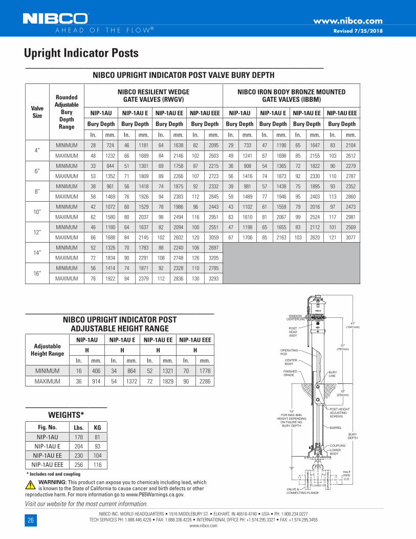
NIBCO UPRIGHT INDICATOR POST VALVE BURY DEPTH
Valve Size
Rounded Adjustable
Bury Depth Range
NIBCO RESILIENT WEDGE GATE VALVES (RWGV)
NIBCO IRON BODY BRONZE MOUNTED GATE VALVES (IBBM)
NIP-1AU NIP-1AU E NIP-1AU EE NIP-1AU EEE NIP-1AU NIP-1AU E NIP-1AU EE NIP-1AU EEE
Bury Depth Bury Depth Bury Depth Bury Depth Bury Depth Bury Depth Bury Depth Bury Depth
In. mm. In. mm. In. mm. In. mm. In. mm. In. mm. In. mm. In. mm.
4”MINIMUM 28 724 46 1181 64 1638 82 2095 29 733 47 1190 65 1647 83 2104
MAXIMUM 48 1232 66 1689 84 2146 102 2603 49 1241 67 1698 85 2155 103 2612
6”MINIMUM 33 844 51 1301 69 1758 87 2215 36 908 54 1365 72 1822 90 2279
MAXIMUM 53 1352 71 1809 89 2266 107 2723 56 1416 74 1873 92 2330 110 2787
8”MINIMUM 38 961 56 1418 74 1875 92 2332 39 981 57 1438 75 1895 93 2352
MAXIMUM 58 1469 76 1926 94 2383 112 2845 59 1489 77 1946 95 2403 113 2860
10”MINIMUM 42 1072 60 1529 78 1986 96 2443 43 1102 61 1559 79 2016 97 2473
MAXIMUM 62 1580 80 2037 98 2494 116 2951 63 1610 81 2067 99 2524 117 2981
12”MINIMUM 46 1180 64 1637 82 2094 100 2551 47 1198 65 1655 83 2112 101 2569
MAXIMUM 66 1688 84 2145 102 2602 120 3059 67 1706 85 2163 103 2620 121 3077
14”MINIMUM 52 1326 70 1783 88 2240 106 2697
MAXIMUM 72 1834 90 2291 108 2748 126 3205
16”MINIMUM 56 1414 74 1871 92 2328 110 2785
MAXIMUM 76 1922 94 2379 112 2836 130 3293
NIBCO UPRIGHT INDICATOR POST ADJUSTABLE HEIGHT RANGE
Adjustable Height Range
NIP-1AU NIP-1AU E NIP-1AU EE NIP-1AU EEE
H H H H
In. mm. In. mm. In. mm. In. mm.
MINIMUM 16 406 34 864 52 1321 70 1778
MAXIMUM 36 914 54 1372 72 1829 90 2286
Upright Indicator Posts
WEIGHTS*Fig . No . Lbs . KG
NIP-1AU 178 81NIP-1AU E 204 93
NIP-1AU EE 230 104NIP-1AU EEE 256 116
* Includes rod and coupling
Revised 7/25/2018
WARNING: This product can expose you to chemicals including lead, which is known to the State of California to cause cancer and birth defects or other
reproductive harm. For more information go to www.P65Warnings.ca.gov.

27NIBCO INC. WORLD HEADQUARTERS • 1516 MIDDLEBURY ST. • ELKHART, IN 46516-4740 • USA • PH: 1.800.234.0227
TECH SERVICES PH: 1.888.446.4226 • FAX: 1.888.336.4226 • INTERNATIONAL OFFICE PH: +1.574.295.3327 • FAX: +1.574.295.3455 www.nibco.com
Visit our website for the most current information.
www.nibco.com A H E A D O F T H E F L O W®
Wall Mount Indicator PostsFire Protection • Wall Mount Style • For Use with Non-Rising Stem Indicator Post Style Gate Valves
UL/ULC LISTED • FM APPROVED
NIP-2AW
MATERIAL LIST PART SPECIFICATION 1 . Upper Body Ductile Iron ASTM A536 Gr . 65-45-12 2 . Cap Ductile Iron ASTM A536 Gr . 65-45-12 3 . T-Head Bolt, Cap (2) Zinc Plated Steel ASTM A105 4 . Nut, Cap (2) Zinc Plated Steel ASTM A105 5 . Operating Stem Bronze ASTM B584 C84400 / B62 C83600 6 . Retaining Ring, Stem Stainless Steel ASTM A276 S30400 7 . Leading Bogie Bronze ASTM B584 C84400 / B62 C83600 8 . Target Plate, OPEN (2) Aluminum ASTM B26 9 . Target Plate, SHUT (2) Aluminum ASTM B26 10 . Extension Plate (2) Steel, Painted Black ASTM A1008 11 . Target Rod (2) Brass ASTM B16 C36000 12 . View Window (2) Polycarbonate Commercial 13 . Gasket, Window (2) Rubber ASTM D2000 EPDM 14 . Guard, Window (2) Cast Iron ASTM B124 Gr . B 15 . Handwheel Ductile Iron ASTM A536 Gr . 65-45-12 16 . Eyebolt, Handwheel Zinc Plated Forged Steel ASTM A105 17 . Washer, Handwheel Retainer Zinc Plated Steel Commercial 19 . Screw, Hex Head Cap (4) Stainless Steel S30400 20 . Washer (4) Stainless Steel S30400 21 . Screw, Slotted Flat Head (4) Stainless Steel S30400 22 . Plug 1/2” Pipe Zinc Plated Steel Commercial 23 . U-Bolt Forged Steel ASTM A105 24 . Cotter Pin Stainless Steel S30400 25 . Coupling, Operating Rod Ductile Iron ASTM A536 Gr . 65-45-12 26 . Operating Rod Steel ASTM A105 27 . Flange, Threaded Ductile Iron ASTM A536 Gr . 65-45-12 37 . Screw, Socket Head Set (6) Stainless Steel S30400
DIMENSIONAL DATA FOR NIBCO RWGV AND IBBM GATE VALVES
Valve Size
NIBCO RESILIENT WEDGE GATE VALVES (RWGV)
NIBCO IRON BODY BRONZE MOUNTEDGATE VALVES (IBBM)
TURNS TO OPEN
A B 1/2 Pipe OD TURNS TO OPEN
A B 1/2 Pipe OD
In . mm . In . mm . In . mm . In . mm . In . mm . In . mm .4” 13 13 .46 342 10 .12 257 2 .40 61 9 14 .13 359 10 .47 266 2 .40 616” 15 .7 17 .01 432 13 .78 350 3 .45 88 13 .5 18 .54 471 16 .30 414 3 .45 888” 17 .3 20 .47 520 17 .32 440 4 .53 115 17 .5 22 .13 562 18 .11 460 4 .53 11510” 21 .4 23 .82 605 20 .71 526 5 .50 140 30 .3 25 .75 654 21 .89 556 5 .50 14012” 25 .3 27 .01 686 23 .86 606 6 .60 168 38 .3 29 .49 749 24 .57 624 6 .60 16814” 44 31 .81 808 28 .58 726 7 .65 194 16” 50 34 .21 869 30 .98 787 8 .70 221
STANDARD LENGTH**30" (762mm)
PATENT #US 9,541,218
Revised 7/25/2018
NIP-2AWWall Mount
WEIGHT*Fig . No . Lbs . KG
NIP-2AW 89 40* Includes rod and coupling
** Longer operating rods available . See installation operation guide on page 59 .
C
WARNING: This product can expose you to chemicals including lead, which is known to the State of California to cause cancer and birth defects or other reproductive harm. For more information go to www.P65Warnings.ca.gov.

28NIBCO INC. WORLD HEADQUARTERS • 1516 MIDDLEBURY ST. • ELKHART, IN 46516-4740 • USA • PH: 1.800.234.0227
TECH SERVICES PH: 1.888.446.4226 • FAX: 1.888.336.4226 • INTERNATIONAL OFFICE PH: +1.574.295.3327 • FAX: +1.574.295.3455 www.nibco.com
Visit our website for the most current information.
www.nibco.com A H E A D O F T H E F L O W®
Lead-Free 250 PSI CWP Iron Body Grooved Silent Check ValvesFire Protection • Twin Disc • Grooved Style • Bronze Disc • Nitrile • Spring Actuated
250 PSI/17 .2 Bar Non-Shock Cold Working PressureMaximum Temperature to 180°F/82°C @ 220 PSI/15 Bar
CERTIFIED LEAD-FREE BY WQA TO NSF/ANSI 372 CONFORMS TO ANSI/AWWA C606 FOR STEEL IPS PIPE
• UL/ULC LISTED • FM APPROVED
KG-900-W-LFGrooved
DIMENSIONS—WEIGHTS—QUANTITIES Dimensions Size A B C D KG-900-W-LF In . mm . In . mm . In . mm . In . mm . In . mm . Lbs . Kg . 21/2 65 4 .91 125 4 .88 124 2 .88 73 2 .41 61 4 .50 2 .04 3 80 5 .31 135 5 .38 137 3 .50 89 2 .94 75 7 .30 3 .31 4 100 5 .38 137 6 .00 152 4 .50 114 3 .91 99 8 .60 3 .90 5 125 5 .72 145 7 .06 179 5 .56 141 4 .89 124 13 .00 5 .90 6 150 6 .00 152 8 .13 206 6 .63 168 5 .92 150 18 .00 8 .17 8 200 6 .72 171 10 .03 255 8 .63 219 7 .91 201 30 .00 13 .6 10 250 7 .78 198 12 .38 314 10 .75 273 10 .00 254 56 .00 25 .4 12 300 8 .19 208 14 .38 365 12 .75 324 11 .94 303 81 .80 36 .7
NOTE: Twin Disc Check Valves can be installed horizontally or in the vertical position with flow up . CAUTION: For horizontal flow applications, the valve must be installed with disc hinge pin in the vertical position to insure proper operation . WARNING: 1 . These are not to be used as steam valves 2 . Valves are not to be used near a reciprocating air compressor 3 . Install 5 pipe diameters minimum downstream from pump discharge or elbows to avoid flow turbulence . Flow straighteners may be required in extreme cases . NOTE: On pump discharge, the preferred check valves are in-line spring loaded .
Groove dimensions conform to ANSI/AWWA specification C606 Table 4 (Cut Groove Dimensions)
MATERIAL LIST PART SPECIFICATION 1 . Body Ductile Iron ASTM A536 Grade 65-45-12 w/Buna-N (Nitrile) resilient seat molded to body 2 . Disc Bronze ASTM B584 Alloy C87600 3 . Torsion Spring Stainless Steel UNS 31600 ASTM A313 4 . Disc Hinge Pin Stainless Steel UNS 31600 ASTM A276 5 . Disc Stop Pin Stainless Steel UNS 31600 ASTM A276 6 . Disc Thrust Bearing Stainless Steel UNS 31600 ASTM A240 7 . Hinge Pin Retainer Stainless Steel UNS 31600 8 . Stop Pin Retainer Stainless Steel UNS 31600 9 . Stabilization Sphere Buna-N 10 . Spacer Stainless Steel UNS 31600 ASTM A276Sizes 10" and 12" furnished with lifting eyebolt
COMPONENT LEAD-FREE
*Lead Free refers to the wetted surface of pipe, fittings and fixtures in potable water systems that have a weighted average lead content ≤ 0 .25% per the Safe Drinking Water Act (Sec . 1417) amended 1-4-2011 and other equivalent state regulations .
Revised 7/25/2018
WARNING: This product can expose you to chemicals including lead, which is known to the State of California to cause cancer
and birth defects or other reproductive harm. For more information go to www.P65Warnings.ca.gov.
LEAD-FREE: Weighted average lead content <0.25%

29NIBCO INC. WORLD HEADQUARTERS • 1516 MIDDLEBURY ST. • ELKHART, IN 46516-4740 • USA • PH: 1.800.234.0227
TECH SERVICES PH: 1.888.446.4226 • FAX: 1.888.336.4226 • INTERNATIONAL OFFICE PH: +1.574.295.3327 • FAX: +1.574.295.3455 www.nibco.com
Visit our website for the most current information.
www.nibco.com A H E A D O F T H E F L O W®
350 PSI CWP Iron Body Grooved Silent Check ValveFire Protection • Twin Disc • Grooved Style • Bronze Disc • Nitrile • Spring Actuated
350 PSI/24 Bar Non-Shock Cold Working PressureMaximum Temperature to 180°F/82°C @ 220 PSI/15 Bar
CERTIFIED LEAD-FREE* BY WQA TO NSF/ANSI 372 CONFORMS TO ANSI/AWWA C606 FOR STEEL IPS PIPE
• UL/ULC LISTED
KG-900-W-LF 350Grooved
DIMENSIONS—WEIGHTS—QUANTITIES Dimensions Size A B C D KG-900-W-LF 350 In . mm . In . mm . In . mm . In . mm . In . mm . Lbs . Kg . 21/2 65 4 .91 125 4 .88 124 2 .88 73 2 .41 61 4 .50 2 .04 3 80 5 .31 135 5 .38 137 3 .50 89 2 .94 75 7 .30 3 .31 4 100 5 .38 137 6 .00 152 4 .50 114 3 .91 99 8 .60 3 .90 6 150 6 .00 152 8 .13 206 6 .63 168 5 .92 150 18 .00 8 .17 8 200 6 .72 171 10 .03 255 8 .63 219 7 .91 201 30 .00 13 .60 10 250 7 .78 198 12 .38 314 10 .75 273 10 .00 254 56 .00 25 .40
NOTE: Twin Disc Check Valves can be installed horizontally or in the vertical position with flow up . CAUTION: For horizontal flow applications, the valve must be installed with disc hinge pin in the vertical position to insure proper operation . WARNING: 1 . These are not to be used as steam valves 2 . Valves are not to be used near a reciprocating air compressor 3 . Install 5 pipe diameters minimum downstream from pump discharge or elbows to avoid flow turbulence . Flow straighteners may be required in extreme cases . NOTE: On pump discharge, the preferred check valves are in-line spring loaded .
Groove dimensions conform to ANSI/AWWA specification C606 Table 4 (Cut Groove Dimensions)
MATERIAL LIST PART SPECIFICATION 1 . Body Ductile Iron ASTM A536 Grade 65-45-12 w/Buna-N (Nitrile) resilient seat molded to body 2 . Disc Bronze ASTM B584 Alloy C83600 3 . Torsion Spring Stainless Steel UNS 31600 ASTM A313 4 . Disc Hinge Pin Stainless Steel UNS 31600 ASTM A276 5 . Disc Stop Pin Stainless Steel UNS 31600 ASTM A276 6 . Disc Thrust Bearing Stainless Steel UNS 31600 ASTM A240 7 . Hinge Pin Retainer Stainless Steel UNS 31600 8 . Stop Pin Retainer Stainless Steel UNS 31600 l 9 . Stabilization Sphere Buna-N 10 . Spacer Stainless Steel UNS 31600 ASTM A276Size 10" furnished with lifting eyebolt
*Lead Free refers to the wetted surface of pipe, fittings and fixtures in potable water systems that have a weighted average lead content ≤ 0 .25% per the Safe Drinking Water Act (Sec . 1417) amended 1-4-2011 and other equivalent state regulations .
Revised 7/25/2018
C
WARNING: This product can expose you to chemicals including lead, which is known to the State of California to cause cancer
and birth defects or other reproductive harm. For more information go to www.P65Warnings.ca.gov.
COMPONENT LEAD-FREE

30NIBCO INC. WORLD HEADQUARTERS • 1516 MIDDLEBURY ST. • ELKHART, IN 46516-4740 • USA • PH: 1.800.234.0227
TECH SERVICES PH: 1.888.446.4226 • FAX: 1.888.336.4226 • INTERNATIONAL OFFICE PH: +1.574.295.3327 • FAX: +1.574.295.3455 www.nibco.com
Visit our website for the most current information.
www.nibco.com A H E A D O F T H E F L O W®
Fire Protection Valve • UL listed FM ApprovedDouble-Door • Wafer Style • Rubber Seat • Spring Actuated
MATERIAL LIST PART SPECIFICATION Ductile Iron ASTM A536, Grade 65-45-12 - 21/2" thru 12" 1 . Body 14" thru 16" Cast Iron ASTM 126, Class B w/ Buna-N (Nitrile) resilient seat molded to body
2 . Disc Bronze ASTM B584 Alloy C87600 (21/2" - 12")
Aluminum Bronze ASTM B148, C95200 (14"-16") 3 . Torsion Spring Stainless Steel UNS 31600 ASTM A313 4 . Hinge Pin Stainless Steel UNS 31600 ASTM A276 5 . Stop Pin Stainless Steel UNS 31600 ASTM A276 6 . Thrust Bearing Stainless Steel UNS 31600 ASTM A240 7 . Hinge Pin Retainer Stainless Steel UNS 31600 8 . Stop Pin Retainer Stainless Steel UNS 31600 9 . Stabilization Sphere Buna-N 10 . Spacer Stainless Steel UNS S31600 ASTM A276
CERTIFIED LEAD-FREE BY WQA TO NSF/ANSI 372 UL/ULC LISTED • FM APPROVED*
sizes 2-1/2" - 12" only
KW-900-W-LFWafer Style 21/2" - 12"
(excluding 5" & 6")
KW-900-W-LF Wafer
Drawing for sizes 21/2" thru 12"DIMENSIONS—WEIGHTS—QUANTITIES Dimensions Size A B C D E Weight In . mm . In . mm . In . mm . In . mm . In . mm . In . mm . C/V Lbs . Kg . 21/2 65 2 .38 60 6 .00 152 .125 3 3 .50 89 1 .313 33 108 4 .3 1 .95 3 80 2 .63 67 5 .63 143 .188 5 3 .875 98 1 .688 43 178 6 .1 2 .77 4 100 2 .63 67 7 .75 197 .625 16 4 .75 121 3 .063 78 440 8 .8 3 .99 5 125 3 .25 83 7 .56 192 .813 21 5 .50 140 3 .625 92 560 13 .0 5 .90 6 150 3 .75 95 8 .63 219 .813 21 6 .25 159 4 .250 108 840 18 .0 8 .16 8 200 5 .00 127 12 .25 311 1 .000 25 8 .00 203 5 .500 140 1600 37 .0 16 .78 10 250 5 .50 140 14 .75 375 2 .060 54 10 .25 257 8 .500 216 2700 65 .0 29 .48 12 300 7 .13 181 17 .38 441 1 .938 49 12 .00 305 9 .250 235 4700 94 .0 42 .64 14 350 7 .25 184 17 .75 451 3 .250 83 14 .38 — 12 .500 330 5200 200 .0 90 .75 16 400 7 .50 191 20 .25 514 4 .500 114 16 .38 — 15 .000 381 7200 285 .0 129 .28*Note: 14” and 16” sizes, 150 PSI WWP, FM approved only – P .O .A .
Features• Spring loaded for fast closure, eliminating reverse flow slam and water hammer .• Easily installed, with gasket, between standard class 125 flanges .• Only one set of flange studs is needed .• May be installed in both horizontal and vertical lines with upward flow .
NOTE: Twin Disc Check Valves can be installed horizontally or in the vertical position with flow up . CAUTION: For horizontal flow applications, the valve must be installed with disc hinge pin in the vertical position to insure proper operation .WARNING: 1 . These are not to be used as steam valves 2 . Valves are not to be used near a reciprocating air compressor 3 . Install 5 pipe diameters minimum downstream from pump discharge or elbows to avoid flow turbulence . Flow straighteners may be required in extreme cases . NOTE: On pump discharge, the preferred check valves are in-line spring loaded .
KW-900-W-LFWafer Style
Body Style 5", 6", 14" & 16"
Lead-Free 250 PSI WWP Iron Body Check Valves
COMPONENT LEAD-FREE
Revised 11/15/2021
WARNING: This product can expose you to chemicals including lead, which is known to the State of California to cause cancer
and birth defects or other reproductive harm. For more information go to www.P65Warnings.ca.gov.*Lead Free refers to the wetted surface of pipe, fittings and fixtures in potable water
systems that have a weighted average lead content ≤ 0 .25% per the Safe Drinking Water Act (Sec . 1417) amended 1-4-2011 and other equivalent state regulations .
LEAD-FREE: Weighted average lead content <0.25%

31NIBCO INC. WORLD HEADQUARTERS • 1516 MIDDLEBURY ST. • ELKHART, IN 46516-4740 • USA • PH: 1.800.234.0227
TECH SERVICES PH: 1.888.446.4226 • FAX: 1.888.336.4226 • INTERNATIONAL OFFICE PH: +1.574.295.3327 • FAX: +1.574.295.3455 www.nibco.com
Visit our website for the most current information.
www.nibco.com A H E A D O F T H E F L O W®
175 PSI WWP Iron Body Check ValvesFire Protection Valve • Bolted Bonnet • Horizontal Swing • Renewable Seat and Disc •Drilled and Tapped for Ball Drip Outlet
MATERIAL LIST PART SPECIFICATION 1 . Pipe Plug Cast Iron or Steel 2 . Bonnet Cast Iron ASTM A126 Class B 3 . Bonnet Gasket Non Asbestos 4 . Bonnet Bolt and Nut Steel ASTM A307 5 . Hinge Plug Cast Bronze B584 Alloy C84400 (not shown)
6 . Hinge Pin Brass ASTM B16 7 . Disc Hanger Nut Cast Bronze B584 Alloy C84400 8 . Disc Stud Bolt Brass ASTM B16 Alloy C36000 9 . Disc Cage Cast Iron ASTM A126 Class B
or Malleable Iron ASTM A 47 (not shown)
10 . Disc Plate Cast Bronze B584 Alloy C84400 11 . Disc Hanger Cast Bronze B584 Alloy C84400 12 . Disc Nut Brass ASTM B16 Alloy C36000 13 . Seat Ring Cast Bronze B584 Alloy C84400 14 . Disc Rubber (W) 15 . Body Cast Iron ASTM A126 Class B
NOTE: 1.Sizes 2½, 3, 5, & 10 are manufactured, listed and approved by Kennedy Valve and distributed by NIBCO.
2. Material list applies to sizes 4", 6", 8", 12" only. 3. All sizes are drilled and tapped ¾" at Boss "C" for ball drip. 4. NIBCO may substitute Ductile Iron ASTM A395 (60-40-18) for ASTM A126 Class
B Cast Iron for the Body, Bonnet, Wedge, or Disc. NIBCO may substitute Ductile Iron ASTM A395 (60-40-18) or ASTM A536 (65-45-12) for all other ASTM A126 Class B Cast Iron components.
175 PSI/12 .1 Bar Non-Shock Cold Water
CONFORMS TO MSS SP-71 • UL/ULC LISTED* • FM APPROVED • APPROVED BY THE NEW YORK CITY
B .S .A . 143-69-SA
An automatic ball drip is available for NIBCO Underwriter's check valves . The ball drip is installed at boss location "C" on the check valve of the fire department connection . It will close against pressure, but will open when pressure is off allowing water to drain from the fire department connection .NOTE: Must be installed in horizontal position .
³⁄₄" Ball Drip # RG 2210090° Street Elbow #T046227 PP
F-908-WFlanged
F-908-W Flg x Flg
Ball Drip
DIMENSIONS—WEIGHTS—QUANTITIES Dimensions Size A B C D Weight In . mm . In . mm . In . mm . In . mm . In . mm . Lbs . Kg . 2¹⁄₂ 65 10 .00 254 6 .44 164 7 .00 178 .69 17 53 24 3 80 10 .25 260 6 .63 168 7 .50 191 .75 19 62 28 4 100 13 .00 330 8 .00 203 9 .00 229 .94 24 103 47 5 125 15 .00 381 9 .19 233 10 .00 254 1 .00 25 145 66 6 150 16 .25 413 10 .31 262 11 .00 279 1 .00 25 174 79 8 200 19 .50 495 11 .50 292 13 .50 343 1 .13 29 290 132 10 250 22 .00 559 13 .31 338 16 .00 406 1 .19 30 490 223 12 300 27 .50 699 15 .56 395 19 .00 483 1 .25 32 683 310NIBCO Iron Body check valves may be installed in both horizontal and vertical lines with upward flow .
* Compliance with the Canadian Requirements per ULC Subject 312 and the Standard for Check Valves, UL 312 .
Revised 4/20/2020
WARNING: This product can expose you to chemicals including lead, which is known to the State of California to cause cancer
and birth defects or other reproductive harm. For more information go to www.P65Warnings.ca.gov.

32NIBCO INC. WORLD HEADQUARTERS • 1516 MIDDLEBURY ST. • ELKHART, IN 46516-4740 • USA • PH: 1.800.234.0227
TECH SERVICES PH: 1.888.446.4226 • FAX: 1.888.336.4226 • INTERNATIONAL OFFICE PH: +1.574.295.3327 • FAX: +1.574.295.3455 www.nibco.com
Visit our website for the most current information.
www.nibco.com A H E A D O F T H E F L O W®
250 PSI WWP Iron Body Check ValvesReliable Automatic Sprinkler "G" Series Fire Protection Valve • Drilled & Tapped for Ball Drip Outlet • EPDM Seal • Bronze Seat • Stainless Steel Disc & Spring Actuated
MATERIAL LIST PART SPECIFICATION *1 . Valve Body Cast Iron, ASTM A48 Class 30A 2 . Seat Bronze C83600 or C93200, ASTM B505 3 . Clapper Stainless Steel 304, ASTM A240 **4 . Facing Seal EPDM Rubber 5 . Clamping Ring Stainless Steel 304, ASTM A240 **6 . Gasket EPDM Rubber 7 . Spring Stainless Steel 302, ASTM A313 8 . Hinge Pin Stainless Steel 303, ASTM A582 9 . Bolt Stainless Steel 304, ASTM F593 **10 . Locknut Stainless Steel 303, ASTM F594 11 . Plug ¹⁄₈" NPT Steel 12 . Plug ¹⁄₂" NPT Steel* Not field replaceable .** Replacement seal kit .NOTE: All sizes are manufactured, listed and approved by Automatic Sprinkler and distributed by NIBCO . All sizes drilled and tapped ½" for a ball drip .
250 PSI/17 .2 Bar Non-Shock Cold Water
GROOVES CONFORM TO ANSI AWWA C-606 FOR STEEL PIPE • UL/ULC LISTED • FM APPROVED •
APPROVED BY THE NEW YORK CITY MEA 258-93-E
G-917-W
G-917-W (Reliable "G" Series)
Grooved
DIMENSIONS—WEIGHTS—QUANTITIES Dimension Size A Weight In . mm . In . mm . Lbs . Kg . 2¹⁄₂ 65 7 .03 179 9 4 3 80 7 .62 194 11 5 4 100 8 .44 214 17 8 6 150 10 .25 260 38 17
An automatic ball drip is available for NIBCO Underwriter's check valves . The ball drip is installed at boss location "C" on the check valve of the fire department connection . It will close against pressure, but will open when pressure is off allowing water to drain from the fire department connection .NOTE: Must be installed in horizontal position .
½" Ball Drip # RG 2200090° Street Elbow #T046212 PP
Revised 7/25/2018
Ball DripWARNING: This product can expose you to chemicals including lead, which is known to the State of California to cause cancer
and birth defects or other reproductive harm. For more information go to www.P65Warnings.ca.gov.
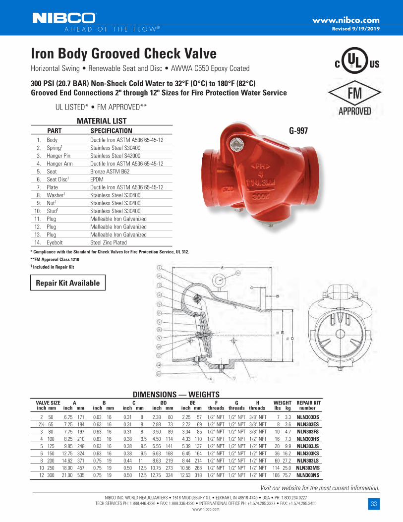
33NIBCO INC. WORLD HEADQUARTERS • 1516 MIDDLEBURY ST. • ELKHART, IN 46516-4740 • USA • PH: 1.800.234.0227
TECH SERVICES PH: 1.888.446.4226 • FAX: 1.888.336.4226 • INTERNATIONAL OFFICE PH: +1.574.295.3327 • FAX: +1.574.295.3455 www.nibco.com
Visit our website for the most current information.
www.nibco.com A H E A D O F T H E F L O W®
Horizontal Swing • Renewable Seat and Disc • AWWA C550 Epoxy Coated
300 PSI (20.7 BAR) Non-Shock Cold Water to 32°F (O°C) to 180°F (82°C)Grooved End Connections 2" through 12" Sizes for Fire Protection Water Service
1. Body Ductile Iron ASTM A536 65-45-12 2. Spring1 Stainless Steel S30400 3. Hanger Pin Stainless Steel S42000 4. Hanger Arm Ductile Iron ASTM A536 65-45-12 5. Seat Bronze ASTM B62 6. Seat Disc1 EPDM 7. Plate Ductile Iron ASTM A536 65-45-12 8. Washer1 Stainless Steel S30400 9. Nut1 Stainless Steel S30400 10. Stud1 Stainless Steel S30400 11. Plug Malleable Iron Galvanized 12. Plug Malleable Iron Galvanized 13. Plug Malleable Iron Galvanized 14. Eyebolt Steel Zinc Plated
MATERIAL LIST PART SPECIFICATION
UL LISTED* • FM APPROVED**
Iron Body Grooved Check Valve
* Compliance with the Standard for Check Valves for Fire Protection Service, UL 312.
**FM Approval Class 12101 Included in Repair Kit
DIMENSIONS — WEIGHTS VALVE SIZE A B C ØD ØE F G H WEIGHT REPAIR KIT inch mm inch mm inch mm inch mm inch mm inch mm threads threads threads lbs kg number
2 50 6.75 171 0.63 16 0.31 8 2.38 60 2.25 57 1/2" NPT 1/2" NPT 3/8" NPT 7 3.3 NLN303DS 2½ 65 7.25 184 0.63 16 0.31 8 2.88 73 2.72 69 1/2" NPT 1/2" NPT 3/8" NPT 8 3.6 NLN303ES 3 80 7.75 197 0.63 16 0.31 8 3.50 89 3.34 85 1/2" NPT 1/2" NPT 3/8" NPT 10 4.7 NLN303FS 4 100 8.25 210 0.63 16 0.38 9.5 4.50 114 4.33 110 1/2" NPT 1/2" NPT 1/2" NPT 16 7.3 NLN303HS 5 125 9.85 248 0.63 16 0.38 9.5 5.56 141 5.39 137 1/2" NPT 1/2" NPT 1/2" NPT 20 9.9 NLN303JS 6 150 12.75 324 0.63 16 0.38 9.5 6.63 168 6.45 164 1/2" NPT 1/2" NPT 1/2" NPT 36 16.2 NLN303KS 8 200 14.62 371 0.75 19 0.44 11 8.63 219 8.44 214 1/2" NPT 1/2" NPT 1/2" NPT 60 27.2 NLN303LS 10 250 18.00 457 0.75 19 0.50 12.5 10.75 273 10.56 268 1/2" NPT 1/2" NPT 1/2" NPT 114 25.0 NLN303MS 12 300 21.00 535 0.75 19 0.50 12.5 12.75 324 12.53 318 1/2" NPT 1/2" NPT 1/2" NPT 166 75.7 NLN303NS
G-997
Repair Kit Available
Revised 9/19/2019

34NIBCO INC. WORLD HEADQUARTERS • 1516 MIDDLEBURY ST. • ELKHART, IN 46516-4740 • USA • PH: 1.800.234.0227
TECH SERVICES PH: 1.888.446.4226 • FAX: 1.888.336.4226 • INTERNATIONAL OFFICE PH: +1.574.295.3327 • FAX: +1.574.295.3455 www.nibco.com
Visit our website for the most current information.
www.nibco.com A H E A D O F T H E F L O W®
UL - FM ApprovedIron Body Gate Valve
Outside screw and yokeBronze Trim, Solid Wedge
350 PSI WWP UL/300 PSI WWP FM
F-697-OSizes 21/2" thru 10"
Class 250 Flanged EndsPage 37
Hi Rise ValvesIllustrated Index
Ductile Iron Body Gate ValveOutside screw and yoke
Bronze Trim, Solid Wedge285 PSI WWP
F-637-31Sizes 2" thru 12"
Class 150 Flanged-Raised FacePage 35
Iron Body Gate Valve Outside screw and yoke
Bronze Trim, Solid Wedge500 PSI WWP
F-667-OSizes 2" thru 12"
Class 250 Flanged EndsPage 36
Ductile Iron Body Swing Check ValveBronze Trim
285 PSI WWP
F-938-31Sizes 2" thru 12"
Class 150 Flanged-Raised FacePage 38
Iron Body Swing Check ValveBronze Trim
500 PSI WWP
F-968-BSizes 21/2" thru 6"
Class 250 Flanged EndsPage 39
Revised 9/8/2021
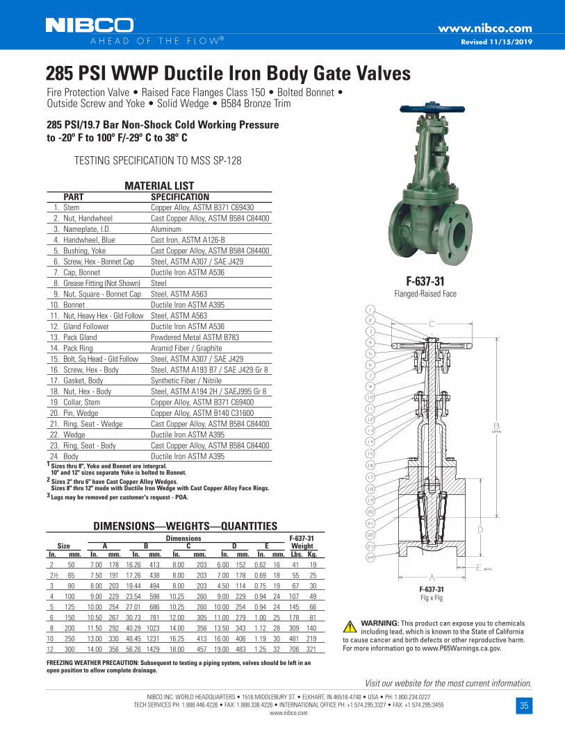
35NIBCO INC. WORLD HEADQUARTERS • 1516 MIDDLEBURY ST. • ELKHART, IN 46516-4740 • USA • PH: 1.800.234.0227
TECH SERVICES PH: 1.888.446.4226 • FAX: 1.888.336.4226 • INTERNATIONAL OFFICE PH: +1.574.295.3327 • FAX: +1.574.295.3455 www.nibco.com
Visit our website for the most current information.
www.nibco.com A H E A D O F T H E F L O W®
DIMENSIONS—WEIGHTS—QUANTITIES Dimensions F-637-31 Size A B C D E Weight In . mm . In . mm . In . mm . In . mm . In . mm . In . mm . Lbs . Kg . 2 50 7 .00 178 16 .26 413 8 .00 203 6 .00 152 0 .62 16 41 19 21/2 65 7 .50 191 17 .26 438 8 .00 203 7 .00 178 0 .69 18 55 25 3 80 8 .00 203 19 .44 494 8 .00 203 4 .50 114 0 .75 19 67 30 4 100 9 .00 229 23 .54 598 10 .25 260 9 .00 229 0 .94 24 107 49 5 125 10 .00 254 27 .01 686 10 .25 260 10 .00 254 0 .94 24 145 66 6 150 10 .50 267 30 .73 781 12 .00 305 11 .00 279 1 .00 25 178 81 8 200 11 .50 292 40 .29 1023 14 .00 356 13 .50 343 1 .12 28 309 140 10 250 13 .00 330 48 .45 1231 16 .25 413 16 .00 406 1 .19 30 481 219 12 300 14 .00 356 56 .26 1429 18 .00 457 19 .00 483 1 .25 32 706 321
MATERIAL LIST PART SPECIFICATION 1 . Stem Copper Alloy, ASTM B371 C69430 2 . Nut, Handwheel Cast Copper Alloy, ASTM B584 C84400 3 . Nameplate, I .D . Aluminum 4 . Handwheel, Blue Cast Iron, ASTM A126-B 5 . Bushing, Yoke Cast Copper Alloy, ASTM B584 C84400 6 . Screw, Hex - Bonnet Cap Steel, ASTM A307 / SAE J429 7 . Cap, Bonnet Ductile Iron ASTM A536 8 . Grease Fitting (Not Shown) Steel 9 . Nut, Square - Bonnet Cap Steel, ASTM A563 10 . Bonnet Ductile Iron ASTM A395 11 . Nut, Heavy Hex - Gld Follow Steel, ASTM A563 12 . Gland Follower Ductile Iron ASTM A536 13 . Pack Gland Powdered Metal ASTM B783 14 . Pack Ring Aramid Fiber / Graphite 15 . Bolt, Sq Head - Gld Follow Steel, ASTM A307 / SAE J429 16 . Screw, Hex - Body Steel, ASTM A193 B7 / SAE J429 Gr 8 17 . Gasket, Body Synthetic Fiber / Nitrile 18 . Nut, Hex - Body Steel, ASTM A194 2H / SAEJ995 Gr 8 19 . Collar, Stem Copper Alloy, ASTM B371 C69400 20 . Pin, Wedge Copper Alloy, ASTM B140 C31600 21 . Ring, Seat - Wedge Cast Copper Alloy, ASTM B584 C84400 22 . Wedge Ductile Iron ASTM A395 23 . Ring, Seat - Body Cast Copper Alloy, ASTM B584 C84400 24 . Body Ductile Iron ASTM A3951 Sizes thru 8", Yoke and Bonnet are intergral . 10" and 12" sizes separate Yoke is bolted to Bonnet .2 Sizes 2" thru 6" have Cast Copper Alloy Wedges . Sizes 8" thru 12" made with Ductile Iron Wedge with Cast Copper Alloy Face Rings .3 Lugs may be removed per customer's request - POA .
285 PSI WWP Ductile Iron Body Gate ValvesFire Protection Valve • Raised Face Flanges Class 150 • Bolted Bonnet •Outside Screw and Yoke • Solid Wedge • B584 Bronze Trim
285 PSI/19 .7 Bar Non-Shock Cold Working Pressureto -20º F to 100º F/-29º C to 38º C
TESTING SPECIFICATION TO MSS SP-128
F-637-31Flanged-Raised Face
F-637-31 Flg x Flg
FREEZING WEATHER PRECAUTION: Subsequent to testing a piping system, valves should be left in an open position to allow complete drainage .
Revised 11/15/2019
WARNING: This product can expose you to chemicals including lead, which is known to the State of California
to cause cancer and birth defects or other reproductive harm. For more information go to www.P65Warnings.ca.gov.

36NIBCO INC. WORLD HEADQUARTERS • 1516 MIDDLEBURY ST. • ELKHART, IN 46516-4740 • USA • PH: 1.800.234.0227
TECH SERVICES PH: 1.888.446.4226 • FAX: 1.888.336.4226 • INTERNATIONAL OFFICE PH: +1.574.295.3327 • FAX: +1.574.295.3455 www.nibco.com
Visit our website for the most current information.
www.nibco.com A H E A D O F T H E F L O W®
FREEZING WEATHER PRECAUTION: Subsequent to testing a piping system, valves should be left in an open position to allow complete drainage .
DIMENSIONS—WEIGHTS—QUANTITIES Dimensions F-667-O Size A B C D E Weight In . mm . In . mm . In . mm . In . mm . In . mm . In . mm . Lbs . Kg . 2 50 8 .50 216 16 .06 408 8 .00 203 6 .50 165 0 .87 22 56 25 21/2 65 9 .50 241 18 .31 465 8 .00 203 7 .50 191 1 .00 25 74 34 3 80 11 .12 282 21 .46 545 10 .25 260 8 .25 210 1 .12 28 122 55 4 100 12 .00 305 23 .53 598 10 .25 260 10 .00 254 1 .25 32 193 88 5 125 15 .00 381 29 .74 755 14 .00 356 11 .00 279 1 .37 35 297 135 6 150 15 .87 403 33 .11 841 16 .25 413 12 .50 318 1 .44 37 411 187 8 200 16 .50 419 45 .84 1164 16 .25 413 15 .00 381 1 .62 41 637 290 10 250 18 .00 457 54 .43 1383 20 .00 508 17 .50 445 1 .87 47 897 408 12 300 19 .75 502 57 .96 1472 20 .00 508 20 .50 521 2 .00 51 1172 533
MATERIAL LIST PART SPECIFICATION 1 . Stem Copper Alloy, ASTM B16 C36000 2 . Nut, Handwheel Cast Copper Alloy, ASTM B584 C84400 3 . Nameplate, I .D . Aluminum 4 . Handwheel, Blue Cast Iron, ASTM A126-B 5 . Bushing, Yoke Cast Copper Alloy, ASTM B584 C84400 6 . Screw, Hex - Bonnet Cap Steel, ASTM A307 / SAE J429 7 . Cap, Bonnet Ductile Iron ASTM A536 8 . Nut, Square - Bonnet Cap Steel, ASTM A563 9 . Bonnet Cast Iron, ASTM A126-B 10 . Nut, Heavy Hex - Gld Follow Steel, ASTM A563 11 . Gland Follower Ductile Iron ASTM A536 12 . Pack Gland Powdered Metal ASTM B783 13 . Pack Ring Aramid Fibers / Graphite 14 . Bolt, Sq Head - Gld Follow Steel, ASTM A307 / SAE J429 15 . Screw, Hex - Body Steel, ASTM A307 / SAE J429 16 . Gasket, Body Reinforced Flexible Graphite 17 . Nut, Hex - Body Steel, ASTM A563 18 . Collar, Stem Copper Alloy, ASTM B16 C36000 19 . Nut, Wedge Cast Copper Alloy, ASTM B584 C84400 20 . Ring, Seat - Wedge Cast Copper Alloy, ASTM B584 C84400 21 . Pin, Wedge Copper Alloy, ASTM B140 C31600 22 . Wedge Cast Iron, ASTM A126-B 23 . Ring, Seat - Body Cast Copper Alloy, ASTM B584 C84400 24 . Body Cast Iron, ASTM A126-B1 Sizes thru 6", Yoke and Bonnet are intergral . 8" and 12" sizes separate Yoke is bolted to Bonnet .2 Sizes 2" thru 3" have Cast Copper Alloy Wedges . Sizes 4" thru 12" made with Cast Iron Wedge with Cast Copper Alloy Face Rings .3 Cast Copper Wedge Nuts used on Sizes 5" thru 12" . 4 2" thru 8" have Aramid Fibers/Graphite packings . 10" & 12" have Wire reinforced
carbon yarn with resilient core/Graphite & Zinc finish .
500 PSI WWP Iron Body Gate ValvesFire Protection Valve • Bolted Bonnet • Outside Screw and Yoke • Solid Wedge • Bronze Mounted • Class 250 Flanges
500 PSI/34 .5 Bar Non-Shock Cold Working Pressure -20º F to 150º F/-29º C to 66º C
CONFORMS TO MSS SP-70 • APPROVED BY THE NEW YORK CITY B .S .A . 143-69-SA AT 350 PSI
NON-SHOCK COLD WATER
F-667-OFlanged
F-667-O Flg x Flg
Revised 4/20/2020
WARNING: This product can expose you to chemicals including lead, which is known to the State of California to
cause cancer and birth defects or other reproductive harm. For more information go to www.P65Warnings.ca.gov.
NOTE: NIBCO may substitute Ductile Iron ASTM A395 (60-40-18) for ASTM A126 Class B Cast Iron for the Body, Bonnet, Wedge, or Disc. NIBCO may substitute Ductile Iron ASTM A395 (60-40-18) or ASTM A536 (65-45-12) for all other ASTM A126 Class B Cast Iron components.
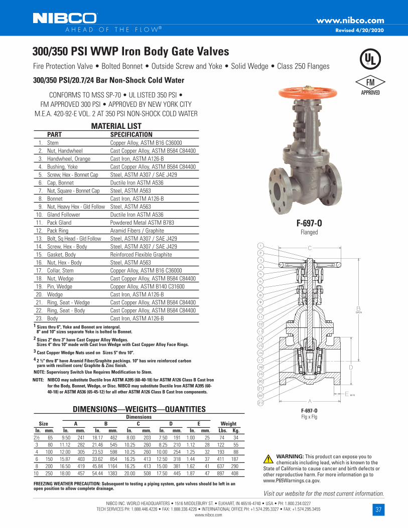
37NIBCO INC. WORLD HEADQUARTERS • 1516 MIDDLEBURY ST. • ELKHART, IN 46516-4740 • USA • PH: 1.800.234.0227
TECH SERVICES PH: 1.888.446.4226 • FAX: 1.888.336.4226 • INTERNATIONAL OFFICE PH: +1.574.295.3327 • FAX: +1.574.295.3455 www.nibco.com
Visit our website for the most current information.
www.nibco.com A H E A D O F T H E F L O W®
300/350 PSI WWP Iron Body Gate ValvesFire Protection Valve • Bolted Bonnet • Outside Screw and Yoke • Solid Wedge • Class 250 Flanges
MATERIAL LIST PART SPECIFICATION 1 . Stem Copper Alloy, ASTM B16 C36000 2 . Nut, Handwheel Cast Copper Alloy, ASTM B584 C84400 3 . Handwheel, Orange Cast Iron, ASTM A126-B 4 . Bushing, Yoke Cast Copper Alloy, ASTM B584 C84400 5 . Screw, Hex - Bonnet Cap Steel, ASTM A307 / SAE J429 6 . Cap, Bonnet Ductile Iron ASTM A536 7 . Nut, Square - Bonnet Cap Steel, ASTM A563 8 . Bonnet Cast Iron, ASTM A126-B 9 . Nut, Heavy Hex - Gld Follow Steel, ASTM A563 10 . Gland Follower Ductile Iron ASTM A536 11 . Pack Gland Powdered Metal ASTM B783 12 . Pack Ring Aramid Fibers / Graphite 13 . Bolt, Sq Head - Gld Follow Steel, ASTM A307 / SAE J429 14 . Screw, Hex - Body Steel, ASTM A307 / SAE J429 15 . Gasket, Body Reinforced Flexible Graphite 16 . Nut, Hex - Body Steel, ASTM A563 17 . Collar, Stem Copper Alloy, ASTM B16 C36000 18 . Nut, Wedge Cast Copper Alloy, ASTM B584 C84400 19 . Pin, Wedge Copper Alloy, ASTM B140 C31600 20 . Wedge Cast Iron, ASTM A126-B 21 . Ring, Seat - Wedge Cast Copper Alloy, ASTM B584 C84400 22 . Ring, Seat - Body Cast Copper Alloy, ASTM B584 C84400 23 . Body Cast Iron, ASTM A126-B1 Sizes thru 6", Yoke and Bonnet are intergral . 8" and 10" sizes separate Yoke is bolted to Bonnet .2 Sizes 2" thru 3" have Cast Copper Alloy Wedges . Sizes 4" thru 10" made with Cast Iron Wedge with Cast Copper Alloy Face Rings .3 Cast Copper Wedge Nuts used on Sizes 5" thru 10" .4 2 ½" thru 8" have Aramid Fiber/Graphite packings . 10" has wire reinforced carbon
yarn with resilient core/ Graphite & Zinc finish .NOTE: Supervisory Switch Use Requires Modification to Stem .
300/350 PSI/20 .7/24 Bar Non-Shock Cold Water
CONFORMS TO MSS SP-70 • UL LISTED 350 PSI • FM APPROVED 300 PSI • APPROVED BY NEW YORK CITY
M .E .A . 420-92-E VOL . 2 AT 350 PSI NON-SHOCK COLD WATER
F-697-OFlanged
F-697-O Flg x Flg
DIMENSIONS—WEIGHTS—QUANTITIES Dimensions Size A B C D E Weight In . mm . In . mm . In . mm . In . mm . In . mm . In . mm . Lbs . Kg .21/2 65 9 .50 241 18 .17 462 8 .00 203 7 .50 191 1 .00 25 74 34 3 80 11 .12 282 21 .46 545 10 .25 260 8 .25 210 1 .12 28 122 55 4 100 12 .00 305 23 .53 598 10 .25 260 10 .00 254 1 .25 32 193 88 6 150 15 .87 403 33 .62 854 16 .25 413 12 .50 318 1 .44 37 411 187 8 200 16 .50 419 45 .84 1164 16 .25 413 15 .00 381 1 .62 41 637 29010 250 18 .00 457 54 .44 1383 20 .00 508 17 .50 445 1 .87 47 897 408
FREEZING WEATHER PRECAUTION: Subsequent to testing a piping system, gate valves should be left in an open position to allow complete drainage .
Revised 4/20/2020
WARNING: This product can expose you to chemicals including lead, which is known to the
State of California to cause cancer and birth defects or other reproductive harm. For more information go to www.P65Warnings.ca.gov.
NOTE: NIBCO may substitute Ductile Iron ASTM A395 (60-40-18) for ASTM A126 Class B Cast Iron for the Body, Bonnet, Wedge, or Disc. NIBCO may substitute Ductile Iron ASTM A395 (60-40-18) or ASTM A536 (65-45-12) for all other ASTM A126 Class B Cast Iron components.

38NIBCO INC. WORLD HEADQUARTERS • 1516 MIDDLEBURY ST. • ELKHART, IN 46516-4740 • USA • PH: 1.800.234.0227
TECH SERVICES PH: 1.888.446.4226 • FAX: 1.888.336.4226 • INTERNATIONAL OFFICE PH: +1.574.295.3327 • FAX: +1.574.295.3455 www.nibco.com
Visit our website for the most current information.
www.nibco.com A H E A D O F T H E F L O W®
285 PSI WWP Ductile Iron Body Swing Check ValvesFire Protection Valve • Class 150 • Raised Face Flanges • Bolted Bonnet • B584 Bronze Trim
285 PSI/19 .7 Bar Non-Shock Cold Working Pressure-20º F to 100º F/-29º C to 38º C
TESTING SPECIFICATION TO MSS SP-136
F-938-31Flanged-Raised Face
F-938-31 Flg x Flg
MATERIAL LIST PART SPECIFICATION 1 . Bolt Steel ASTM A193 B7 /SAE J429 Gr8 2 . Identification Plate Aluminum 3 . Bonnet Ductile Iron ASTM A395 4 . Body Gasket Synthetic Fibres 5 . Nut Steel ASTM A194 2H/SAE J995 Gr8 6 . Side Plug Bronze ASTM B584 7 . Hanger Pin Bronze ASTM B371 8 . Hanger Bronze ASTM B584 or Ductile Iron ASTM A536 *9 . Disc Bronze ASTM B584 10 . Seat Ring Bronze ASTM B584 11 . Disc Nut Bronze ASTM B371 12 . Body Ductile Iron ASTM A395
DIMENSIONS—WEIGHTS—QUANTITIES Dimensions F-938-31 Size A B D E Weight In . mm . In . mm . In . mm . In . mm . In . mm . Lbs . Kg . 2 50 8 .00 203 3 .94 100 6 .00 152 .63 16 24 11 2¹⁄₂ 65 8 .50 216 4 .50 114 7 .00 178 .69 17 35 16 3 80 9 .50 241 5 .13 130 7 .50 191 .75 19 47 21 4 100 11 .50 292 6 .13 156 9 .00 229 .94 24 81 37 5 125 13 .00 330 6 .81 173 10 .00 254 .94 24 100 45 6 150 14 .00 356 8 .00 203 11 .00 279 1 .00 25 146 66 8 200 19 .50 495 9 .44 240 13 .50 343 1 .13 29 255 116 10 250 24 .50 622 12 .06 306 16 .00 406 1 .19 30 426 193 12 300 27 .50 699 16 .13 410 19 .00 483 1 .25 32 660 299Lever and Weight/Spring Options available .
*2"-4" have bronze disc; 5"-12" have ductile iron disc with bronze seat ring
NIBCO Check Valves may be installed in both horizontal and vertical lines with upward flow or in any intermediate position .
Warning: Do not use for Reciprocating Air Compressor Service .
Revised 11/15/2019
WARNING: This product can expose you to chemicals including lead, which is known to the State of California to cause cancer and birth defects or other
reproductive harm. For more information go to www.P65Warnings.ca.gov.

39NIBCO INC. WORLD HEADQUARTERS • 1516 MIDDLEBURY ST. • ELKHART, IN 46516-4740 • USA • PH: 1.800.234.0227
TECH SERVICES PH: 1.888.446.4226 • FAX: 1.888.336.4226 • INTERNATIONAL OFFICE PH: +1.574.295.3327 • FAX: +1.574.295.3455 www.nibco.com
Visit our website for the most current information.
www.nibco.com A H E A D O F T H E F L O W®
DIMENSIONS—WEIGHTS—QUANTITIES Dimensions F-968-B Size A B D E Weight In . mm . In . mm . In . mm . In . mm . In . mm . Lbs . Kg . 2¹⁄₂ 65 11 .50 292 5 .83 149 7 .50 191 1 .00 25 62 28 3 80 12 .50 318 6 .31 160 8 .25 210 1 .13 29 77 35 4 100 14 .00 356 7 .56 192 10 .00 254 1 .25 32 129 58 6 150 17 .50 445 8 .50 216 12 .50 318 1 .44 37 225 102* Proper machining facilities required .
NIBCO Iron Body Check Valves may be installed in both horizontal and vertical lines with upward flow or in any intermediate position .
WARNING: Do not use for Reciprocating Air Compressor Service .
MATERIAL LIST PART SPECIFICATION 1 . Body Bolt Steel ASTM A307 2 . Identification Plate Aluminum 3 . Bonnet Cast Iron ASTM A126 Class B 4 . Body Gasket Reinforced Graphite 5 . Body Nut Steel ASTM A307 6 . Side Plug Brass ASTM B16 Alloy C36000 7 . Hanger Pin Brass ASTM B16 Alloy C36000 8 . Hanger Cast Bronze ASTM B584 Alloy C84400 9 . Disc Nut Cast Bronze ASTM B584 Alloy C84400 10 . Disc Cast Bronze ASTM B584 Alloy C84400 11 . Seat Ring Cast Bronze ASTM B584 Alloy C84400 12 . Body Cast Iron ASTM A126 Class B
500 PSI WWP Iron Body Check ValvesFire Protection Valve • Bolted Bonnet • Horizontal Swing • *Renewable Bronze Seat and Disc •Class 250 Flanges
500 PSI/34 .5 Bar Non-Shock Cold Working Pressure-20º F to 150º F/-29º C to 66º C
CONFORMS TO MSS SP-71 TYPE 1 •APPROVED BY NEW YORK CITY B .S .A . 143-69-SA AT 350 PSI
NON-SHOCK COLD WATER
F-968-BFlanged
F-968-B Flg x Flg
Revised 4/20/2020
WARNING: This product can expose you to chemicals including lead, which is known to the State of California to cause cancer and birth defects or other
reproductive harm. For more information go to www.P65Warnings.ca.gov.
NOTE: NIBCO may substitute Ductile Iron ASTM A395 (60-40-18) for ASTM A126 Class B Cast Iron for the Body, Bonnet, Wedge, or Disc. NIBCO may substitute Ductile Iron ASTM A395 (60-40-18) or ASTM A536 (65-45-12) for all other ASTM A126 Class B Cast Iron components.
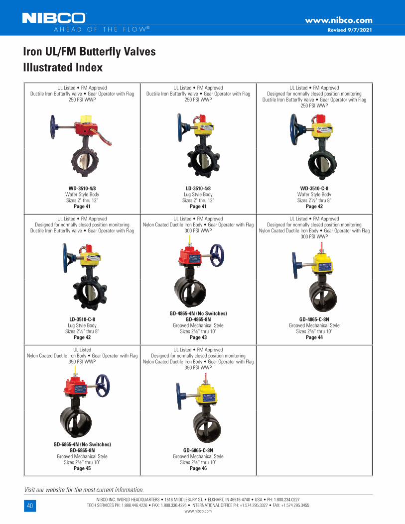
40NIBCO INC. WORLD HEADQUARTERS • 1516 MIDDLEBURY ST. • ELKHART, IN 46516-4740 • USA • PH: 1.800.234.0227
TECH SERVICES PH: 1.888.446.4226 • FAX: 1.888.336.4226 • INTERNATIONAL OFFICE PH: +1.574.295.3327 • FAX: +1.574.295.3455 www.nibco.com
Visit our website for the most current information.
www.nibco.com A H E A D O F T H E F L O W®
Iron UL/FM Butterfly ValvesIllustrated Index
Revised 9/7/2021
UL Listed • FM ApprovedDuctile Iron Butterfly Valve • Gear Operator with Flag
250 PSI WWP
UL Listed • FM ApprovedDuctile Iron Butterfly Valve • Gear Operator with Flag
250 PSI WWP
UL Listed • FM ApprovedDesigned for normally closed position monitoring
Ductile Iron Butterfly Valve • Gear Operator with Flag250 PSI WWP
WD-3510-4/8Wafer Style BodySizes 2" thru 12"
Page 41
LD-3510-4/8Lug Style Body
Sizes 2" thru 12"Page 41
WD-3510-C-8Wafer Style BodySizes 2¹⁄₂" thru 8"
Page 42
UL Listed • FM ApprovedDesigned for normally closed position monitoring
Ductile Iron Butterfly Valve • Gear Operator with Flag
UL Listed • FM ApprovedNylon Coated Ductile Iron Body • Gear Operator with Flag
300 PSI WWP
UL Listed • FM ApprovedDesigned for normally closed position monitoring
Nylon Coated Ductile Iron Body • Gear Operator with Flag300 PSI WWP
LD-3510-C-8Lug Style Body
Sizes 2¹⁄₂" thru 8"Page 42
GD-4865-4N (No Switches)GD-4865-8N
Grooved Mechanical StyleSizes 2¹⁄₂" thru 10"
Page 43
GD-4865-C-8NGrooved Mechanical Style
Sizes 2¹⁄₂" thru 10"Page 44
UL ListedNylon Coated Ductile Iron Body • Gear Operator with Flag
350 PSI WWP
UL Listed • FM ApprovedDesigned for normally closed position monitoring
Nylon Coated Ductile Iron Body • Gear Operator with Flag350 PSI WWP
GD-6865-4N (No Switches)GD-6865-8N
Grooved Mechanical StyleSizes 2¹⁄₂" thru 10"
Page 45
GD-6865-C-8NGrooved Mechanical Style
Sizes 2¹⁄₂" thru 10"Page 46

41NIBCO INC. WORLD HEADQUARTERS • 1516 MIDDLEBURY ST. • ELKHART, IN 46516-4740 • USA • PH: 1.800.234.0227
TECH SERVICES PH: 1.888.446.4226 • FAX: 1.888.336.4226 • INTERNATIONAL OFFICE PH: +1.574.295.3327 • FAX: +1.574.295.3455 www.nibco.com
Visit our website for the most current information.
www.nibco.com A H E A D O F T H E F L O W®
MATERIAL LIST PART SPECIFICATION 1 . Stem Stainless Steel ASTM 582 Type 416 2 . Collar Bushing Brass ASTM B124 3 . Upper Bushing Copper Alloy CDA 122 4 . Stem Seal EPDM 5 . Body Seal EPDM 6 . Disc Ductile Iron ASTM 395 (Nickel Plated) 7 . Liner EPDM 8 . Lower Bushing Copper Alloy CDA 122 9 . Nameplate Aluminum 10 . Body Ductile Iron ASTM A536 11 . Gear Operator Cast Iron and Steel 12 . Indicator Flag Cast Iron 13 . Handwheel Cast Iron
WD-3510-8** Wafer
(4" Shown)
250 PSI/17 .2 Bar Non-Shock Cold Water
DESIGNED TO COMPLY WITH MSS SP-67 • UL/ULC LISTED • FM APPROVED • 2" - 12" UL/FM LISTED FOR INDOOR AND OUTDOOR SERVICE • APPROVED BY NEW
YORK CITY MEA 90-07-E • CALIFORNIA STATE FIRE MARSHAL LISTING NO . 7770-1243:104 • U .S . COAST GUARD "Category A"
(10" Shown)
250 PSI WWP UL/FM Butterfly ValvesFire Protection Valve • Wafer or Lug Style Body • Molded in Seat • Accepts Internal Supervisory Switches • Mates with C .I . Class 125/Steel Class 150 Flanges
**-8 version has two factory mounted internal supervisory switches . -4 version has no switches .Note: Wafer body will mate with ANSI or ISO flanges . O .D . of wafer body notched to fit ISO bolt circle . For dead-end service use lug style (rated 200 PSI for this service) .
DIMENSIONS—WEIGHTS—QUANTITIES Dimensions Size A B C D E F G H I J In . mm . In . mm . In . mm . In . mm . In . mm . In . mm . In . mm . In . mm . In . mm . In . mm . In . mm . 2 50 2 .53 64 4 .88 124 4 .62 117 5 .38 137 2 .88 73 6 .89 175 12 .75 324 1 .68 43 1 .81 46 2 .91 74 2¹⁄₂ 65 2 .90 74 5 .62 143 5 .12 130 5 .88 149 3 .25 83 7 .36 187 13 .63 346 1 .81 46 1 .94 49 2 .91 74 3 80 3 .17 81 6 .12 155 5 .50 140 6 .12 155 3 .38 86 7 .60 193 14 .00 356 1 .81 46 1 .94 49 2 .91 74 4 100 4 .17 106 7 .00 178 8 .25 210 6 .88 175 4 .00 102 8 .39 213 15 .38 391 2 .06 52 2 .19 56 2 .91 74 5 125 5 .17 131 8 .25 210 9 .38 238 7 .38 187 4 .75 121 8 .86 225 16 .63 422 2 .19 56 2 .31 59 2 .91 74 6 150 6 .17 157 9 .25 235 10 .25 260 8 .00 203 5 .25 133 9 .49 241 17 .75 451 2 .19 56 2 .31 59 2 .91 74 8 200 8 .17 208 11 .62 295 12 .38 314 9 .25 235 6 .50 165 10 .75 273 20 .25 514 2 .38 60 2 .50 64 2 .91 74 10 250 10 .17 258 14 .25 362 15 .50 394 10 .50 267 8 .00 203 12 .28 312 23 .50 597 2 .68 69 2 .81 71 3 .90 99 12 300 12 .17 309 16 .75 425 18 .25 464 12 .00 305 9 .25 235 13 .78 350 26 .25 667 3 .00 76 3 .12 79 3 .90 99
Dimensions Flange/Stud Data Weight Size K M N P Dia Wafer Lug BC Lug Wafer In . mm . In . mm . In . mm . In . mm . In . mm . No . In . mm . In . mm . In . mm . In . mm . Lbs . Kg . Lbs . Kg . 2 50 3 .54 90 5 .82 148 2 .13 54 5 .9 150 4 ⁵⁄₈ 16 4 .00 101 1 .25 32 4 .75 121 23 11 21 10 21/2 65 3 .54 90 5 .82 148 2 .13 54 5 .9 150 4 ⁵⁄₈ 16 4 .25 108 1 .50 38 5 .50 140 25 11 24 11 3 80 3 .54 90 5 .82 148 2 .13 54 5 .9 150 4 ⁵⁄₈ 16 4 .25 108 1 .50 38 6 .00 152 26 12 24 11 4 100 3 .54 90 5 .82 148 2 .13 54 5 .9 150 8 ⁵⁄₈ 16 5 .00 127 2 .00 51 7 .50 191 31 14 27 12 5 125 3 .54 90 7 .64 194 2 .13 54 5 .9 150 8 ³⁄₄ 20 5 .25 133 2 .00 51 8 .50 216 37 17 31 14 6 150 3 .54 90 7 .64 194 2 .13 54 5 .9 150 8 ³⁄₄ 20 5 .25 133 2 .00 51 9 .50 241 40 18 34 15 8 200 3 .54 90 7 .91 201 2 .13 54 9 .8 250 8 ³⁄₄ 20 5 .75 146 2 .25 57 11 .75 298 55 25 49 22 10 250 3 .98 101 9 .49 241 3 .03 77 18 .0 457 12 ⁷⁄₈ 22 6 .25 159 2 .50 64 14 .25 362 95 43 78 35 12 300 3 .98 101 9 .49 241 3 .03 77 18 .0 457 12 ⁷⁄₈ 22 6 .75 171 2 .50 64 17 .00 432 123 56 103 47
Revised 7/25/2018
LD-3510-8** Lug
WARNING: This product can expose you to chemicals including lead,
which is known to the State of California to cause cancer and birth defects or other reproductive harm. For more information go to www.P65Warnings.ca.gov.
P347-1

42NIBCO INC. WORLD HEADQUARTERS • 1516 MIDDLEBURY ST. • ELKHART, IN 46516-4740 • USA • PH: 1.800.234.0227
TECH SERVICES PH: 1.888.446.4226 • FAX: 1.888.336.4226 • INTERNATIONAL OFFICE PH: +1.574.295.3327 • FAX: +1.574.295.3455 www.nibco.com
Visit our website for the most current information.
www.nibco.com A H E A D O F T H E F L O W® Revised 11/16/2021
MATERIAL LIST PART SPECIFICATION 1 . Stem Stainless Steel ASTM 582 Type 416 2 . Collar Bushing Brass ASTM B16 3 . Upper Bushing Copper Alloy CDA 122 4 . Stem Seal EPDM 5 . Body Seal EPDM 6 . Disc Ductile Iron ASTM 395 (Nickel Plated) 7 . Liner EPDM 8 . Lower Bushing Copper Alloy CDA 122 9 . Nameplate Aluminum 10 . Body Ductile Iron ASTM A536 11 . Gear Operator Cast Iron and Steel 12 . Indicator Flag Cast Iron 13 . Handwheel Cast Iron
250 PSI/17 .2 bar non-shock cold water
THIRD PARTY CERTIFIED BY QAI TO MEET MSS SP-67 STANDARD • UL/ULC LISTED** • FM APPROVED** • CERTIFIED LEAD FREE BY TRUESDAIL LABS
2¹⁄₂" - 8" UL LISTED FOR INDOOR AND OUTDOOR SERVICE • CALIFORNIA FIRE MARSHALL
Warning: these valves are not to be used between the water source and sprinkler head .
250 PSI WWP UL/FM Butterfly Valves
Fire Protection Valve • Lug or Wafer Style Body • Factory Mounted Monitoring Switches • Mates with C .I . Class 125 and Steel Class 150 Flanges
Note: wafer body will mate with ANSI or ISO flanges . O .D . of wafer body notched to fit ISO bolt circle . For dead-end service use lug style (rated 250 PSI for this service) . Comes with two factory mounted internal supervisory switches . Use switch Figure No . TS-4 . See Section VI of the
Rubber-Seated Butterfly Valve O&M Manual .
DIMENSIONS—WEIGHTS—QUANTITIES Dimensions Size A B C D E F G H I J In . mm . In . mm . In . mm . In . mm . In . mm . In . mm . In . mm . In . mm . In . mm . In . mm . In . mm . 21/2 65 2 .90 74 5 .62 143 5 .12 130 5 .88 149 3 .25 83 7 .36 187 13 .63 346 1 .81 46 1 .94 49 2 .91 74 3 80 3 .17 81 6 .12 155 5 .50 140 6 .12 155 3 .38 86 7 .60 193 14 .00 356 1 .81 46 1 .94 49 2 .91 74 4 100 4 .17 106 7 .00 178 8 .25 210 6 .88 175 4 .00 102 8 .39 213 15 .38 391 2 .06 52 2 .19 56 2 .91 74 6 150 6 .17 157 9 .25 235 10 .25 260 8 .00 203 5 .25 133 9 .49 241 17 .75 451 2 .19 56 2 .31 59 2 .91 74 8 200 8 .17 208 11 .62 295 12 .38 314 9 .25 235 6 .50 165 10 .75 273 20 .25 514 2 .38 60 2 .50 64 2 .91 74
Dimensions Flange/Stud Data Weight Size K M N P Dia Wafer Lug BC Lug Wafer In . mm . In . mm . In . mm . In . mm . In . mm . No . In . mm . In . mm . In . mm . In . mm . Lbs . Kg . Lbs . Kg . 21/2 65 3 .54 90 5 .82 148 2 .13 54 5 .9 150 4 5/8 16 4 .25 108 1 .50 38 5 .50 140 25 11 24 11 3 80 3 .54 90 5 .82 148 2 .13 54 5 .9 150 4 5/8 16 4 .25 108 1 .50 38 6 .00 152 26 12 24 11 4 100 3 .54 90 5 .82 148 2 .13 54 5 .9 150 8 5/8 16 5 .00 127 2 .00 51 7 .50 191 31 14 27 12 6 150 3 .54 90 7 .64 194 2 .13 54 5 .9 150 8 3/4 20 5 .25 133 2 .00 51 9 .50 241 40 18 34 15 8 200 3 .54 90 7 .91 201 2 .13 54 9 .8 250 8 3/4 20 5 .75 146 2 .25 57 11 .75 298 55 25 49 22**Compliance with standards for butterfly valves for fire protection UL1091 & FM1112
Designed for normally closed position monitoring
LD-3510-C-8
WD-3510-C-8
P347-1
*Lead Free refers to the wetted surface of pipe, fittings and fixtures in potable water systems that have a weighted average lead content ≤ 0 .25% per the Safe Drinking Water Act (Sec . 1417) amended 1-4-2011 and other equivalent state regulations .
WARNING: This product can expose you to chemicals including lead, which is known to the State of California to cause cancer and birth defects or other reproductive harm. For more information go to www.
P65Warnings.ca.gov.
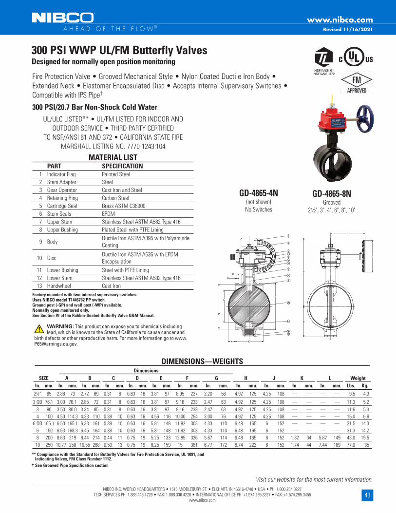
43NIBCO INC. WORLD HEADQUARTERS • 1516 MIDDLEBURY ST. • ELKHART, IN 46516-4740 • USA • PH: 1.800.234.0227
TECH SERVICES PH: 1.888.446.4226 • FAX: 1.888.336.4226 • INTERNATIONAL OFFICE PH: +1.574.295.3327 • FAX: +1.574.295.3455 www.nibco.com
Visit our website for the most current information.
www.nibco.com A H E A D O F T H E F L O W®
UL/ULC LISTED** • UL/FM LISTED FOR INDOOR AND OUTDOOR SERVICE • THIRD PARTY CERTIFIED
TO NSF/ANSI 61 AND 372 • CALIFORNIA STATE FIRE MARSHALL LISTING NO . 7770-1243:104
Fire Protection Valve • Grooved Mechanical Style • Nylon Coated Ductile Iron Body • Extended Neck • Elastomer Encapsulated Disc • Accepts Internal Supervisory Switches • Compatible with IPS Pipe†
GD-4865-8NGrooved
2¹⁄₂", 3", 4", 6", 8", 10"
300 PSI WWP UL/FM Butterfly ValvesDesigned for normally open position monitoring
300 PSI/20 .7 Bar Non-Shock Cold Water
MATERIAL LISTPART SPECIFICATION
1 Indicator Flag Painted Steel2 Stem Adapter Steel3 Gear Operator Cast Iron and Steel4 Retaining Ring Carbon Steel5 Cartridge Seal Brass ASTM C360006 Stem Seals EPDM7 Upper Stem Stainless Steel ASTM A582 Type 4168 Upper Bushing Plated Steel with PTFE Lining
9 Body Ductile Iron ASTM A395 with Polyaminde Coating
10 Disc Ductile Iron ASTM A536 with EPDM Encapsulation
11 Lower Bushing Steel with PTFE Lining12 Lower Stem Stainless Steel ASTM A582 Type 41613 Handwheel Cast Iron
Factory mounted with two internal supervisory switches .Uses NIBCO model T1446762 PP switch .Ground post (-GP) and wall post (-WP) available .Normally open monitored only .See Section VI of the Rubber-Seated Butterfly Valve O&M Manual .
GD-4865-4N(not shown)No Switches
** Compliance with the Standard for Butterfly Valves for Fire Protection Service, UL 1091, and Indicating Valves, FM Class Number 1112 .
† See Grooved Pipe Specification section
DimensionsSIZE A B C D E F G H J K L Weight
In . mm . In . mm . In . mm . In . mm . In . mm . In . mm . In . mm . In . mm . In . mm . In . mm . In . mm . In . mm . Lbs . Kg .
21/2” 65 2 .88 73 2 .72 69 0 .31 8 0 .63 16 3 .81 97 8 .95 227 2 .20 56 4 .92 125 4 .25 108 — — — — 9 .5 4 .3
3 OD 76 .1 3 .00 76 .1 2 .85 72 0 .31 8 0 .63 16 3 .81 97 9 .16 233 2 .47 63 4 .92 125 4 .25 108 — — — — 11 .3 5 .23 80 3 .50 80 .0 3 .34 85 0 .31 8 0 .63 16 3 .81 97 9 .16 233 2 .47 63 4 .92 125 4 .25 108 — — — — 11 .6 5 .34 100 4 .50 114 .3 4 .33 110 0 .38 10 0 .63 16 4 .56 116 10 .00 254 3 .00 76 4 .92 125 4 .25 108 — — — — 15 .0 6 .8
6 OD 165 .1 6 .50 165 .1 6 .33 161 0 .38 10 0 .63 16 5 .81 148 11 .92 303 4 .33 110 6 .48 165 6 152 — — — — 31 .5 14 .36 150 6 .63 168 .3 6 .45 164 0 .38 10 0 .63 16 5 .81 148 11 .92 303 4 .33 110 6 .48 165 6 152 — — — — 31 .3 14 .28 200 8 .63 219 8 .44 214 0 .44 11 0 .75 19 5 .25 133 12 .85 326 5 .67 114 6 .48 165 6 152 1 .32 34 5 .87 149 43 .0 19 .510 250 10 .77 250 10 .55 268 0 .50 13 0 .75 19 6 .25 159 15 381 6 .77 172 8 .74 222 6 152 1 .74 44 7 .44 189 77 .0 35
DIMENSIONS—WEIGHTS
Revised 11/16/2021
WARNING: This product can expose you to chemicals including lead, which is known to the State of California to cause cancer and
birth defects or other reproductive harm. For more information go to www.P65Warnings.ca.gov.

44NIBCO INC. WORLD HEADQUARTERS • 1516 MIDDLEBURY ST. • ELKHART, IN 46516-4740 • USA • PH: 1.800.234.0227
TECH SERVICES PH: 1.888.446.4226 • FAX: 1.888.336.4226 • INTERNATIONAL OFFICE PH: +1.574.295.3327 • FAX: +1.574.295.3455 www.nibco.com
Visit our website for the most current information.
www.nibco.com A H E A D O F T H E F L O W®
300 PSI/20 .7 Bar Non-Shock Cold Water 21⁄2” - 10”Warning: These valves are not to be used between the water source and sprinkler head .
UL/ULC LISTED** • 2¹⁄2" -10" LISTED FOR INDOOR AND OUTDOOR SERVICE • THIRD PARTY CERTIFIED TO NSF/ANSI 61 AND 372 • CALIFORNIA STATE FIRE
MARSHALL LISTING NO . 7770-1243:0500
Fire Protection Valve • Grooved Mechanical Style • Nylon Coated Ductile Iron Body • Extended Neck • Elastomer Encapsulated Disc • Factory Installed Internal Monitoring Switches • Compatible with IPS Pipe†
300 PSI WWP UL/FM Butterfly ValvesDesigned for normally closed position monitoring
GD-4865-C-8N 2¹⁄₂", 3", 4", 6", 8", 10"
** Compliance with the Standard for Butterfly Valves for Fire Protection Service, UL 1091 and Indicating Valves, FM Class Number 1112 .† See Grooved Pipe Specification section
DimensionsSIZE A B C D E F G H J K L Weight
In . mm . In . mm . In . mm . In . mm . In . mm . In . mm . In . mm . In . mm . In . mm . In . mm . In . mm . In . mm . Lbs . Kg .
21/2” 65 2 .88 73 2 .72 69 0 .31 8 0 .63 16 3 .81 97 8 .95 227 2 .20 56 4 .92 125 4 .25 108 — — — — 9 .5 4 .3
3 OD 76 .1 3 .00 76 .1 2 .85 72 0 .31 8 0 .63 16 3 .81 97 9 .16 233 2 .47 63 4 .92 125 4 .25 108 — — — — 11 .3 5 .23 80 3 .50 80 .0 3 .34 85 0 .31 8 0 .63 16 3 .81 97 9 .16 233 2 .47 63 4 .92 125 4 .25 108 — — — — 11 .6 5 .34 100 4 .50 114 .3 4 .33 110 0 .38 10 0 .63 16 4 .56 116 10 .00 254 3 .00 76 4 .92 125 4 .25 108 — — — — 15 .0 6 .8
6 OD 165 .1 6 .50 165 .1 6 .33 161 0 .38 10 0 .63 16 5 .81 148 11 .92 303 4 .33 110 6 .48 165 6 152 — — — — 31 .5 14 .36 150 6 .63 168 .3 6 .45 164 0 .38 10 0 .63 16 5 .81 148 11 .92 303 4 .33 110 6 .48 165 6 152 — — — — 31 .3 14 .28 200 8 .63 219 8 .44 214 0 .44 11 0 .75 19 5 .25 133 12 .85 326 5 .67 114 6 .48 165 6 152 1 .32 34 5 .87 149 43 .0 19 .510 250 10 .77 250 10 .55 268 0 .50 13 0 .75 19 6 .25 159 15 381 6 .77 172 8 .74 222 6 152 1 .74 44 7 .44 189 77 .0 35
DIMENSIONS—WEIGHTS
MATERIAL LISTPART SPECIFICATION
1 Indicator Flag Painted Steel2 Stem Adapter Steel3 Gear Operator Cast Iron and Steel4 Retaining Ring Carbon Steel5 Cartridge Seal Brass ASTM C360006 Stem Seals EPDM7 Upper Stem Stainless Steel ASTM A582 Type 4168 Upper Bushing Plated Steel with PTFE Lining
9 Body Ductile Iron ASTM A395 with Polyaminde Coating
10 Disc Ductile Iron ASTM A536 with EPDM Encapsulation
11 Lower Bushing Steel with PTFE Lining12 Lower Stem Stainless Steel ASTM A582 Type 41613 Handwheel Cast Iron
Note: Comes with two factory mounted internal supervisory switches . Uses NIBCO model T1447532 PP switch . See Section VI of the Rubber-Seated Butterfly Valve O&M Manual . Ground post or wall post not available .
Normally closed monitored .WARNING: This product can expose you to chemicals including lead, which is known to the State of California to cause cancer
and birth defects or other reproductive harm. For more information go to www.P65Warnings.ca.gov.
Revised 11/16/2021

45NIBCO INC. WORLD HEADQUARTERS • 1516 MIDDLEBURY ST. • ELKHART, IN 46516-4740 • USA • PH: 1.800.234.0227
TECH SERVICES PH: 1.888.446.4226 • FAX: 1.888.336.4226 • INTERNATIONAL OFFICE PH: +1.574.295.3327 • FAX: +1.574.295.3455 www.nibco.com
Visit our website for the most current information.
www.nibco.com A H E A D O F T H E F L O W® Revised 11/16/2021
UL/ULC LISTED** • UL/FM LISTED FOR INDOOR AND OUTDOOR SERVICE • THIRD PARTY CERTIFIED TO
NSF/ANSI 61 AND 372 • CALIFORNIA STATE FIRE MARSHALL LISTING NO . 7770-1243:0500
Fire Protection Valve • Grooved Mechanical Style • Nylon Coated Ductile Iron Body • Extended Neck • Elastomer Encapsulated Disc • Internal Supervisory Switches • Compatible with IPS Pipe†
GD-6865-8NGrooved
2¹⁄₂", 3", 4", 6", 8", 10"
350 PSI WWP UL/FM Butterfly ValvesDesigned for normally open position monitoring
350 PSI/24 Bar Non-Shock Cold Water 2½" - 10"
** Compliance with the Standard for Butterfly Valves for Fire Protection Service, UL 1091, and Indicating Values, FM Class Number 1112 .† See Grooved Pipe Specification section
DimensionsSIZE A B C D E F G H J K L Weight
In . mm . In . mm . In . mm . In . mm . In . mm . In . mm . In . mm . In . mm . In . mm . In . mm . In . mm . In . mm . Lbs . Kg .
21/2” 65 2 .88 73 2 .72 69 0 .31 8 0 .63 16 3 .81 97 8 .95 227 2 .20 56 4 .92 125 4 .25 108 — — — — 9 .5 4 .3
3 OD 76 .1 3 .00 76 .1 2 .85 72 0 .31 8 0 .63 16 3 .81 97 9 .16 233 2 .47 63 4 .92 125 4 .25 108 — — — — 11 .3 5 .23 80 3 .50 80 .0 3 .34 85 0 .31 8 0 .63 16 3 .81 97 9 .16 233 2 .47 63 4 .92 125 4 .25 108 — — — — 11 .6 5 .34 100 4 .50 114 .3 4 .33 110 0 .38 10 0 .63 16 4 .56 116 10 .00 254 3 .00 76 4 .92 125 4 .25 108 — — — — 15 .0 6 .8
6 OD 165 .1 6 .50 165 .1 6 .33 161 0 .38 10 0 .63 16 5 .81 148 11 .92 303 4 .33 110 6 .48 165 6 152 — — — — 31 .5 14 .36 150 6 .63 168 .3 6 .45 164 0 .38 10 0 .63 16 5 .81 148 11 .92 303 4 .33 110 6 .48 165 6 152 — — — — 31 .3 14 .28 200 8 .63 219 8 .44 214 0 .44 11 0 .75 19 5 .25 133 12 .85 326 5 .67 114 6 .48 165 6 152 1 .32 34 5 .87 149 43 .0 19 .5
10 250 10 .77 250 10 .55 268 0 .50 13 0 .75 19 6 .25 159 15 381 6 .77 172 8 .74 222 6 152 1 .74 44 7 .44 189 77 .0 35
DIMENSIONS—WEIGHTS
GD-6865-4N(not shown)No Switches
MATERIAL LISTPART SPECIFICATION
1 Indicator Flag Painted Steel2 Stem Adapter Steel3 Gear Operator Cast Iron and Steel4 Retaining Ring Carbon Steel5 Cartridge Seal Brass ASTM C360006 Stem Seals EPDM7 Upper Stem Stainless Steel ASTM A582 Type 4168 Upper Bushing Steel with PTFE Lining
9 Body Ductile Iron ASTM A395 with Polyaminde Coating
10 Disc Ductile Iron ASTM A536 with EPDM Encapsulation
11 Lower Bushing Steel with PTFE Lining12 Lower Stem Stainless Steel ASTM A582 Type 41613 Handwheel Cast Iron
Factory mounted with two internal supervisory switches .Uses NIBCO model T1446762 PP switch .Ground post (-GP) and wall post (-WP) available . Normally open monitored only .Section VI of the Rubber-Seated Butterfly Valve O&M Manual .
WARNING: This product can expose you to chemicals including lead, which is known to the State of California to cause cancer
and birth defects or other reproductive harm. For more information go to www.P65Warnings.ca.gov.

46NIBCO INC. WORLD HEADQUARTERS • 1516 MIDDLEBURY ST. • ELKHART, IN 46516-4740 • USA • PH: 1.800.234.0227
TECH SERVICES PH: 1.888.446.4226 • FAX: 1.888.336.4226 • INTERNATIONAL OFFICE PH: +1.574.295.3327 • FAX: +1.574.295.3455 www.nibco.com
Visit our website for the most current information.
www.nibco.com A H E A D O F T H E F L O W® Revised 11/16/2021
350 PSI/24 Bar Non-Shock Cold Water 21⁄2” - 10"Warning: These valves are not to be used between the water source and sprinkler head .
Fire Protection Valve • Grooved Mechanical Style • Nylon Coated Ductile Iron Body • Extended Neck • Elastomer Encapsulated Disc • Factory Installed Internal Monitoring Switches • Compatible with IPS Pipe
350 PSI WWP UL/FM Butterfly ValvesDesigned for normally closed position monitoring
GD-6865-C-8N
** Compliance with the Standard for Butterfly Valves for Fire Protection Service, UL 1091, and Indicating Valves, FM Class Number 1112 .
† See Grooved Pipe Specification section
DimensionsSIZE A B C D E F G H J K L Weight
In . mm . In . mm . In . mm . In . mm . In . mm . In . mm . In . mm . In . mm . In . mm . In . mm . In . mm . In . mm . Lbs . Kg .
21/2” 65 2 .88 73 2 .72 69 0 .31 8 0 .63 16 3 .81 97 8 .95 227 2 .20 56 4 .92 125 4 .25 108 — — — — 9 .5 4 .3
3 OD 76 .1 3 .00 76 .1 2 .85 72 0 .31 8 0 .63 16 3 .81 97 9 .16 233 2 .47 63 4 .92 125 4 .25 108 — — — — 11 .3 5 .23 80 3 .50 80 .0 3 .34 85 0 .31 8 0 .63 16 3 .81 97 9 .16 233 2 .47 63 4 .92 125 4 .25 108 — — — — 11 .6 5 .34 100 4 .50 114 .3 4 .33 110 0 .38 10 0 .63 16 4 .56 116 10 .00 254 3 .00 76 4 .92 125 4 .25 108 — — — — 15 .0 6 .8
6 OD 165 .1 6 .50 165 .1 6 .33 161 0 .38 10 0 .63 16 5 .81 148 11 .92 303 4 .33 110 6 .48 165 6 152 — — — — 31 .5 14 .36 150 6 .63 168 .3 6 .45 164 0 .38 10 0 .63 16 5 .81 148 11 .92 303 4 .33 110 6 .48 165 6 152 — — — — 31 .3 14 .28 200 8 .63 219 8 .44 214 0 .44 11 0 .75 19 5 .25 133 12 .85 326 5 .67 114 6 .48 165 6 152 1 .32 34 5 .87 149 43 .0 19 .510 250 10 .77 250 10 .55 268 0 .50 13 0 .75 19 6 .25 159 15 381 6 .77 172 8 .74 222 6 152 1 .74 44 7 .44 189 77 .0 35
DIMENSIONS—WEIGHTS
MATERIAL LISTPART SPECIFICATION
1 Indicator Flag Painted Steel2 Stem Adapter Steel3 Gear Operator Cast Iron and Steel4 Retaining Ring Carbon Steel5 Cartridge Seal Brass ASTM C360006 Stem Seals EPDM7 Upper Stem Stainless Steel ASTM A582 Type 4168 Upper Bushing Steel with PTFE Lining
9 Body Ductile Iron ASTM A395 with Polyaminde Coating
10 Disc Ductile Iron ASTM A536 with EPDM Encapsulation
11 Lower Bushing Steel with PTFE Lining12 Lower Stem Stainless Steel ASTM A582 Type 41613 Handwheel Cast Iron
Note: Comes with two factory mounted internal supervisory switches . Uses NIBCO model T1447532 PP switch . See Section VI of the Rubber-Seated Butterfly Valve O&M Manual .
Ground post or wall post not available . Normally closed monitored .
2¹⁄₂", 3", 4", 6", 8", 10"
UL/ULC LISTED** • 2¹⁄2" - 10" LISTED FOR INDOOR AND OUTDOOR SERVICE • THIRD PARTY CERTIFIED TO
NSF/ANSI 61 AND 372 • CALIFORNIA STATE FIRE MARSHALL LISTING NO . 7770-1243:0500
WARNING: This product can expose you to chemicals including lead, which is known to the State of California to cause cancer
and birth defects or other reproductive harm. For more information go to www.P65Warnings.ca.gov.

47NIBCO INC. WORLD HEADQUARTERS • 1516 MIDDLEBURY ST. • ELKHART, IN 46516-4740 • USA • PH: 1.800.234.0227
TECH SERVICES PH: 1.888.446.4226 • FAX: 1.888.336.4226 • INTERNATIONAL OFFICE PH: +1.574.295.3327 • FAX: +1.574.295.3455 www.nibco.com
Visit our website for the most current information.
www.nibco.com A H E A D O F T H E F L O W®
1 2" WD/LD 3510 01 T117725 PP T117850 PP 1/8" SQ. X .38 LG. BRASS 2 2 1/2" & 3" WD/LD 3510 02 T117726 PP T117851 PP 1/8" SQ. X .68 LG. BRASS 3 2 1/2" & 3" GD-4765/6765 02 T117726 PP T117850 PP 1/8" SQ. X .38 LG. BRASS 4 2 1/2" & 3" GD-4865/6865 – T118778 PP T117852 PP 1/8" SQ. X .44 LG. STEEL 5 4" WD/LD 3510 03 T117727 PP T117852 PP 1/8" SQ. X .44 LG. STEEL 6 4" GD-4865/6865 – T1427913 PP T117852 PP 1/8" SQ. X .44 LG. STEEL 7 4" & 5" GD-4765/6765 04 T117728 PP T117853 PP 1/8" SQ. X .29 LG. STEEL 8 5" & 6" WD/LD 3510 04 T117728 PP T117854 PP 1/8" SQ. X .41 LG. STEEL 9 6" & 8" GD-4765/6765 05 T117729 PP T117856 PP 1/8" SQ. X .91 LG. STEEL 10 6" & 8" GD-4865/6865 – T118780 PP T117856 PP 1/8" SQ. X .91 LG. STEEL 11 8" WD/LD 3510 05 T117729 PP T117856 PP 1/8" SQ. X .91 LG. STEEL 12 10" GD-4765/6765 06 T117730 PP T117858 PP 3/16" SQ. X 1.00 LG STEEL 13 10" GD-4865/6865 – T118781 PP T117858 PP 3/16" SQ. X 1.00 LG STEEL 14 10" & 12" WD/LD 3510 07 T117731 PP T117858 PP 3/16" SQ. X 1.00 LG STEEL
ITEM VALVE SIZE VALVE ASSEMBLY FIGURE NUMBER
BUSHING REFERENCE
NUMBER
BUSHING ASSEMBLY
PART NUMBER
DRIVE KEY PART NUMBER DRIVE KEY SIZE DRIVE KEY
MATERIAL
NIBCO Fire Protection Butterfly ValvesGear Operator Bushing and Drive Key Repair Parts

48NIBCO INC. WORLD HEADQUARTERS • 1516 MIDDLEBURY ST. • ELKHART, IN 46516-4740 • USA • PH: 1.800.234.0227
TECH SERVICES PH: 1.888.446.4226 • FAX: 1.888.336.4226 • INTERNATIONAL OFFICE PH: +1.574.295.3327 • FAX: +1.574.295.3455 www.nibco.com
Visit our website for the most current information.
www.nibco.com A H E A D O F T H E F L O W®
D
E
A
G
M
F
C
C
F
M
G
D
EA
LD-3510-4GPLug/Wafer ButterflyUnderground Post Assembly ** (66" standard length)
Butterfly ValvesIndicator Post AssembliesAvailable as Wall Post (WP*) or Underground (GP**)Available with Internal Supervisory Switch 2" - 8" (UL Listed Indoor/Outdoor) - (8N Version)Available with Grooved, Wafer or Lug Style Valves (UL Listed, Not FM Approved)See Tech Bulletin on nibco.com for proper post sizing
GD-4865-8WPGrooved ButterflyWall Post Assembly(22" standard length)
Mounting Hole Size2" - 8" — 51/2" hole diameter10" - 12" — 71/2" hole diameter
A S R E Q U I R E D
* 9" x 9" painted steel wall plate included with wall post assembly .** Ground line to top of indicator should be at least 36" .
Approx . Net Wt . 22" WP Incl . Wall Plate
See NIBCO Butterfly Catalog for stem extension information
Butterfly Post Assembly DIMENSIONS—WEIGHTS—QUANTITIES
2 ---- 4 .25 6 ---- 5 .38 ---- 2 .88 4 .92 4 .6 ---- 50 51
21/2 2 .44 4 .25 6 4 .26 5 .88 2 .20 3 .25 4 .92 4 .6 51 52 53
3 2 .96 4 .25 6 4 .49 6 .13 2 .48 3 .38 4 .92 4 .6 53 53 54
4 3 .86 4 .25 6 5 .32 6 .88 3 .05 4 .00 6 .5 4 .6 56 56 59
5 ---- 5 .17 6 ---- 7 .38 ---- 4 .75 6 .5 5 .5 ---- 59 63
6 5 .76 6 .17 6 7 .09 8 .00 4 .33 5 .25 6 .5 4 .8 ---- 62 68
8 7 .75 8 .17 9 8 .03 9 .25 5 .67 6 .50 6 .5 4 .8 76 74 80
10 ---- 10 .17 9 9 .84 10 .50 6 .75 8 .00 8 .75 5 .1 ---- 91 104
12 ---- 12 .17 9 ---- 12 .00 ---- 9 .25 8 .75 5 .1 ---- 108 128
A D E C F G M
ValveSize Grooved Wafer/
Lug Grooved Wafer/ Lug Grooved Wafer/
Lug Grooved Wafer Lug
WARNING: This product can expose you to chemicals including lead, which is known to the State of California to cause cancer and birth defects or other reproductive harm. For more
information go to www.P65Warnings.ca.gov.
Revised 7/25/2018
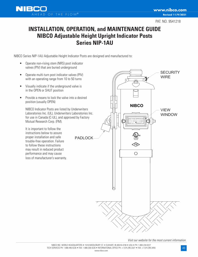
49NIBCO INC. WORLD HEADQUARTERS • 1516 MIDDLEBURY ST. • ELKHART, IN 46516-4740 • USA • PH: 1.800.234.0227
TECH SERVICES PH: 1.888.446.4226 • FAX: 1.888.336.4226 • INTERNATIONAL OFFICE PH: +1.574.295.3327 • FAX: +1.574.295.3455 www.nibco.com
Visit our website for the most current information.
www.nibco.com A H E A D O F T H E F L O W®
INSTALLATION, OPERATION, and MAINTENANCE GUIDENIBCO Adjustable Height Upright Indicator Posts
Series NIP-1AU
PAT . NO . 9541218
NIBCO Series NIP-1AU Adjustable Height Indicator Posts are designed and manufactured to:
• Operate non-rising stem (NRS) post indicator valves (PIV) that are buried underground
• Operate multi-turn post indicator valves (PIV) with an operating range from 10 to 50 turns
• Visually indicate if the underground valve is in the OPEN or SHUT position
• Provide a means to lock the valve into a desired position (usually OPEN)
NIBCO Indicator Posts are listed by Underwriters Laboratories Inc . (UL), Underwriters Laboratories Inc . for use in Canada (C-UL), and approved by Factory Mutual Research Corp . (FM) .
It is important to follow the instructions below to assure proper installation and safe trouble-free operation . Failure to follow these instructions may result in reduced product performance and may cause loss of manufacturer’s warranty .
Revised 11/9/2021

50NIBCO INC. WORLD HEADQUARTERS • 1516 MIDDLEBURY ST. • ELKHART, IN 46516-4740 • USA • PH: 1.800.234.0227
TECH SERVICES PH: 1.888.446.4226 • FAX: 1.888.336.4226 • INTERNATIONAL OFFICE PH: +1.574.295.3327 • FAX: +1.574.295.3455 www.nibco.com
Visit our website for the most current information.
www.nibco.com A H E A D O F T H E F L O W®
1 . Application
1 .1 NIBCO Indicator Posts are primarily used with multi-turn non-rising stem (NRS) post indicator valves (PIV) controlling water supplies to sprinkler, deluge, water spray, foam, and standpipe systems used in fire protection service .
1 .2 NIBCO Indicator Posts are designed for outdoor service and are coated with electrostatically applied fusion bonded epoxy resin to resist corrosion .
1 .3 NIBCO Upright Indicator Posts have a 20” adjustment range, and can be ordered to accommodate various bury depths .
1 .4 NIBCO Indicator Post view targets are adjustable to accommodate valves of various sizes .
1 .5 NIBCO Indicator Posts are shipped for use with “left-hand” (counter-clockwise) opening valves .
1 .6 NIBCO Indicator Posts are designed to allow the attachment of a Control Valve Supervisory Switch for electronic monitoring of the OPEN valve position . Simply follow the instructions provided with the Supervisory Switch for proper installation and operation .
1 .7 NIBCO Upright Indicator Posts are designed to mate and bolt directly to the Post Indicator Valve (PIV) flange; four ¾” holes on a 101/2” diameter bolt circle .
1 .8 Indicator Posts should be inspected on a regular basis .
2 . Indicator Post Selection
2 .1 NIBCO Indicator Posts are designed to work with 4” thru 16” size NIBCO Resilient Wedge Gate Valves (RWGVs) and 4” thru 12” sizes NIBCO Iron Body Bronze Mounted (IBBM) Gate Valves . See Table 1 and Fig . 1 for valve dimensional data . They will also work with any manufacturers non-rising stem Post Indicator Valve (PIV) that operates from 10 to 50 turns, and a maximum operating torque of 900 ft·lbs .
DIMENSIONAL DATA FOR NIBCO RWGV AND IBBM GATE VALVES
VALVE SIZE
NIBCO RESILIENT WEDGE GATE VALVES (RWGV)
NIBCO IRON BODY BRONZE MOUNTEDGATE VALVES (IBBM)
TURNS TO OPEN
A B 1/2 PIPE OD TURNS TO OPEN
A B 1/2 PIPE ODINCH MM INCH MM INCH MM INCH MM INCH MM INCH MM
4” 13 13 .46 342 10 .12 257 2 .40 61 9 14 .13 359 10 .47 266 2 .40 61
6” 15 .7 17 .01 432 13 .78 350 3 .45 88 13 .5 18 .54 471 16 .30 414 3 .45 88
8” 17 .3 20 .47 520 17 .32 440 4 .53 115 17 .5 22 .13 562 18 .11 460 4 .53 115
10” 21 .4 23 .82 605 20 .71 526 5 .50 140 30 .3 25 .75 654 21 .89 556 5 .50 140
12” 25 .3 27 .01 686 23 .86 606 6 .60 168 38 .3 29 .49 749 24 .57 624 6 .60 168
14” 44 31 .81 808 28 .58 726 7 .65 194
16” 50 34 .21 869 30 .98 787 8 .70 221
Table 1

51NIBCO INC. WORLD HEADQUARTERS • 1516 MIDDLEBURY ST. • ELKHART, IN 46516-4740 • USA • PH: 1.800.234.0227
TECH SERVICES PH: 1.888.446.4226 • FAX: 1.888.336.4226 • INTERNATIONAL OFFICE PH: +1.574.295.3327 • FAX: +1.574.295.3455 www.nibco.com
Visit our website for the most current information.
www.nibco.com A H E A D O F T H E F L O W®
UINDP-0613© 2013, NIBCO INC .
2 .2 For Upright Indicator Posts, four Figure No . options are available . See Table 2 .
• NIP-1AU, Standard height
• NIP-1AU E, Extended height
• NIP-1AU EE, Double extended height
• NIP-1AU EEE, Triple extended height
See Table 2 for adjustable height ranges, and Table 3 for Bury Depths .
NIBCO UPRIGHT INDICATOR POST ADJUSTABLE HEIGHT RANGE
ADJUSTABLE HEIGHT RANGE
NIP-1AU NIP-1AU E NIP-1AU EE NIP-1AU EEE
H* H H H
INCH MM INCH MM INCH MM INCH MM
MINIMUM 16 406 34 864 52 1321 70 1778MAXIMUM 36 914 54 1372 72 1829 90 2286
Table 2
*For dimension “H” see Fig . 3
Fig . 1

52NIBCO INC. WORLD HEADQUARTERS • 1516 MIDDLEBURY ST. • ELKHART, IN 46516-4740 • USA • PH: 1.800.234.0227
TECH SERVICES PH: 1.888.446.4226 • FAX: 1.888.336.4226 • INTERNATIONAL OFFICE PH: +1.574.295.3327 • FAX: +1.574.295.3455 www.nibco.com
Visit our website for the most current information.
www.nibco.com A H E A D O F T H E F L O W®
Table 3
NIBCO UPRIGHT INDICATOR POST VALVE BURY DEPTH
VALVE SIZE
*ROUNDED ADJUSTABLE
BURY DEPTH RANGE
NIBCO RESILIENT WEDGE GATE VALVES (RWGV)
NIP-1AU NIP-1AU E NIP-1AU EE NIP-1AU EEE
BURY DEPTH BURY DEPTH BURY DEPTH BURY DEPTH
INCH MM INCH MM INCH MM INCH MM
4”MINIMUM 28 724 46 1181 64 1638 82 2095
MAXIMUM 48 1232 66 1689 84 2146 102 2603
6”MINIMUM 33 844 51 1301 69 1758 87 2215
MAXIMUM 53 1352 71 1809 89 2266 107 2723
8”MINIMUM 38 961 56 1418 74 1875 92 2332
MAXIMUM 58 1469 76 1926 94 2383 112 2845
10”MINIMUM 42 1072 60 1529 78 1986 96 2443
MAXIMUM 62 1580 80 2037 98 2494 116 2951
12”MINIMUM 46 1180 64 1637 82 2094 100 2551
MAXIMUM 66 1688 84 2145 102 2602 120 3059
14”MINIMUM 52 1326 70 1783 88 2240 106 2697
MAXIMUM 72 1834 90 2291 108 2748 126 3205
16”MINIMUM 56 1414 74 1871 92 2328 110 2785
MAXIMUM 76 1922 94 2379 112 2836 130 3293
* INCH DIMENSIONS SHOWN ARE ROUNDED TO THE NEAREST INCH
VALVE SIZE
*ROUNDED ADJUSTABLE
BURY DEPTH RANGE
NIBCO IRON BODY BRONZE MOUNTED GATE VALVES (IBBM)
NIP-1AU NIP-1AU E NIP-1AU EE
BURY DEPTH BURY DEPTH BURY DEPTH
INCH MM INCH MM INCH MM
4”MINIMUM 29 733 47 1190 65 1647
MAXIMUM 49 1241 67 1698 85 2155
6”MINIMUM 36 908 54 1365 72 1822
MAXIMUM 56 1416 74 1873 92 2330
8”MINIMUM 39 981 57 1438 75 1895
MAXIMUM 59 1489 77 1946 95 2403
10”MINIMUM 43 1102 61 1559 79 2016
MAXIMUM 63 1610 81 2067 99 2524
12”MINIMUM 47 1198 65 1655 83 2112
MAXIMUM 67 1706 85 2163 103 2620
* INCH DIMENSIONS SHOWN ARE ROUNDED TO THE NEAREST INCH
53NIBCO INC. WORLD HEADQUARTERS • 1516 MIDDLEBURY ST. • ELKHART, IN 46516-4740 • USA • PH: 1.800.234.0227
TECH SERVICES PH: 1.888.446.4226 • FAX: 1.888.336.4226 • INTERNATIONAL OFFICE PH: +1.574.295.3327 • FAX: +1.574.295.3455 www.nibco.com
Visit our website for the most current information.
www.nibco.com A H E A D O F T H E F L O W®
3 . Installation of Upright Style Indicator Post
3 .1 Fully OPEN the gate valve to which the Indicator Post is being attached .
3 .2 Loosen but do not remove 2 Body Bolts (35) 3 turns . Remove Barrel (32) and Body Base (31) from inside Center Body (30) . Remove Operating Rod (26) from Indicator Post by sliding it out the bottom, See Fig . 2 .
3 .3 Position Body Base (31) on top of buried valve PIV plate and secure with 4 customer supplied bolts, washers, & nuts, See Fig . 3 .
3 .4 Remove Bolt (28), Flatwasher (38), and Lockwasher (39) from Upper Body (1) and lift Head Assembly from Center Body (30) .
3 .5 Slide Center Body (30) over Barrel (32) and slide down until BURY line cast on Center Body is even with planned finished grade soil level . Securely tighten 2 Body Bolts (35) . See Fig . 2 & 3 .
3 .6 Insert 1” square Operating Rod (26) with attached Coupling (25) inside Barrel (32) and fully engage Coupling onto Operating Nut of valve as shown in Fig . 3 . Mark Operating Rod at a distance 10¾” from top edge of Center Body (30), See Fig . 4 . Remove Operating Rod (26) from Barrel (32) and cut off the top section of the 1” square Rod at location you just marked . Remove any sharp edges from the Rod with a file .
3 .7 Reinstall the shortened Operating Rod (26) into Barrel (32), making sure the Coupling (25) is fully engaged on Operating Nut of valve, See Fig . 3 .
3 .8 Reinstall the Head Assembly by sliding the 1” square pocket located in bottom side of Head Assembly onto Operating Rod (26) . Secure Head Assembly to Center Body (30) with Screw (28), Flatwasher (38), and Lockwasher (39) .

54NIBCO INC. WORLD HEADQUARTERS • 1516 MIDDLEBURY ST. • ELKHART, IN 46516-4740 • USA • PH: 1.800.234.0227
TECH SERVICES PH: 1.888.446.4226 • FAX: 1.888.336.4226 • INTERNATIONAL OFFICE PH: +1.574.295.3327 • FAX: +1.574.295.3455 www.nibco.com
Visit our website for the most current information.
www.nibco.com A H E A D O F T H E F L O W®
Fig . 2
Table 4
UPRIGHT STYLE INDICATOR POST PARTS LISTNO . DESCRIPTION MATERIAL SPECIFICATION QTY .
1 UPPER BODY DUCTILE IRON ASTM A536 Gr . 65-45-12 1
2 CAP DUCTILE IRON ASTM A536 Gr . 65-45-12 1
3 T-HEAD BOLT, CAP STEEL, ZINC PLATED ASTM A105 2
4 NUT, CAP STEEL, ZINC PLATED ASTM A105 2
5 OPERATING STEM BRONZE ASTM B584 C84400 / B62 C83600 1
6 RETAINING RING, STEM STAINLESS STEEL ASTM A276 S30400 1
7 LEADING BOGIE BRONZE ASTM B584 C84400 / B62 C83600 1
8 TARGET PLATE, OPEN ALUMINUM ASTM B26 2
9 TARGET PLATE, CLOSED ALUMINUM ASTM B26 2
10 EXTENSION PLATE STEEL, PAINTED BLACK ASTM A1008 2
11 TARGET ROD BRASS ASTM B16 C36000 2
12 VIEW WINDOW POLYCARBONATE COMMERCIAL 2
13 GASKET, WINDOW RUBBER ASTM D2000 EPDM 2
14 GUARD, WINDOW CAST IRON ASTM B124 Gr . B 2
19 SCREW, HEX HEAD CAP STAINLESS STEEL S30400 4
20 WASHER STAINLESS STEEL S30400 4
21 SCREW, SLOTTED FLAT HD . STAINLESS STEEL S30400 4
22 PLUG, 1/2" PIPE STEEL, ZINC PLATED COMMERCIAL 1
23 U-BOLT FORGED STEEL ASTM A105 1
24 COTTER PIN STAINLESS STEEL S30400 1
25 COUPLING, OPERATING ROD DUCTILE IRON ASTM A536 Gr . 65-45-12 1
26 OPERATING ROD STEEL ASTM A105 1
28 SCREW, HEX HEAD CAP STAINLESS STEEL S30400 1
29 WRENCH, OPERATING DUCTILE IRON ASTM A536 Gr . 65-45-12 1
30 CENTER BODY DUCTILE IRON ASTM A536 Gr . 65-45-12 1
31 BASE BODY DUCTILE IRON ASTM A536 Gr . 65-45-12 1
32 BARREL DUCTILE IRON ASTM A536 Gr . 65-45-12 1
33 SCREW, HEX HEAD CAP STAINLESS STEEL S30400 3
35 SCREW, HEX HEAD CAP STAINLESS STEEL S30400 2
37 SCREW, SOCKET HD . SET STAINLESS STEEL S30400 6
38 WASHER, FLAT STAINLESS STEEL S30400 1
39 WASHER, LOCK STAINLESS STEEL S30400 1

55NIBCO INC. WORLD HEADQUARTERS • 1516 MIDDLEBURY ST. • ELKHART, IN 46516-4740 • USA • PH: 1.800.234.0227
TECH SERVICES PH: 1.888.446.4226 • FAX: 1.888.336.4226 • INTERNATIONAL OFFICE PH: +1.574.295.3327 • FAX: +1.574.295.3455 www.nibco.com
Visit our website for the most current information.
www.nibco.com A H E A D O F T H E F L O W®
4 . OPEN and SHUT Target Adjustment
4 .1 All NIBCO Indicator Posts are shipped for use with “left-hand” (counter-clockwise) opening valves .
4 .2 Remove two Nuts (4) and two T-Head Bolts (3) that secure Cap (2) to Indicator Post . See Fig . 2 .
4 .3 Grasp Cap (2) and remove from Indicator Post by lifting upward until Target assembly is clear .
4 .4 Target Plates (8 & 9) must be positioned with the OPEN Plate (8) above the SHUT Plate (9) for “left-hand” (counter-clockwise) opening valves . See Fig . 5 .
Fig . 3
Fig . 4
NIP-IAU

56NIBCO INC. WORLD HEADQUARTERS • 1516 MIDDLEBURY ST. • ELKHART, IN 46516-4740 • USA • PH: 1.800.234.0227
TECH SERVICES PH: 1.888.446.4226 • FAX: 1.888.336.4226 • INTERNATIONAL OFFICE PH: +1.574.295.3327 • FAX: +1.574.295.3455 www.nibco.com
Visit our website for the most current information.
www.nibco.com A H E A D O F T H E F L O W®
TARGET ASSEMBLY PARTS LISTNO . DESCRIPTION MATERIAL SPECIFICATION QTY .
7 LEADING BOGIE BRONZE ASTM B584 C84400 / B62 C83600 1
8 TARGET PLATE, OPEN ALUMINUM ASTM B26 2
9 TARGET PLATE, SHUT ALUMINUM ASTM B26 2
10 EXTENSION PLATE STEEL, PAINTED BLACK ASTM A1008 2
11 TARGET ROD BRASS ASTM B16 C36000 2
21 SCREW, SLOTTED FLAT HD . STAINLESS STEEL S30400 4
37 SCREW, SOCKET HD . SET STAINLESS STEEL S30400 6
Table 5
Fig . 5
4 .5 Position OPEN Target Plates (8) so they are in the full upward position for “left-hand” (counter-clockwise) opening valves . Secure OPEN Target Plates (8) by tightening Screws (37a) . See Fig . 6 .
4 .6 Determine the number of turns required to fully open the valve . See Table 1 for NIBCO valves . You should always confirm actual turns required to open the valve by counting them .
4 .7 Using Table 6, choose the closest “Number of Turns to Open Valve” and the corresponding “Distance Between Targets” dimension “X” .
4 .8 Measure and position both SHUT Target Plates (9) at dimension “X” from OPEN Target Plates (8) . See Fig . 6 .
4 .9 Secure both SHUT Target Plates (9) by tightening Screws (37a) with an Allen wrench .
NOTE: Only half of assembly is shown
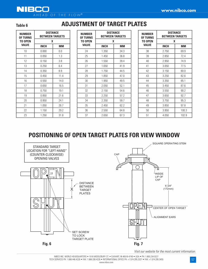
57NIBCO INC. WORLD HEADQUARTERS • 1516 MIDDLEBURY ST. • ELKHART, IN 46516-4740 • USA • PH: 1.800.234.0227
TECH SERVICES PH: 1.888.446.4226 • FAX: 1.888.336.4226 • INTERNATIONAL OFFICE PH: +1.574.295.3327 • FAX: +1.574.295.3455 www.nibco.com
Visit our website for the most current information.
www.nibco.com A H E A D O F T H E F L O W®
NUMBER OF TURNS TO OPEN
VALVE
DISTANCE BETWEEN TARGETS
X
INCH MM
10 0 .000 0 .0
11 0 .050 1 .3
12 0 .150 3 .8
13 0 .250 6 .4
14 0 .350 8 .9
15 0 .450 11 .4
16 0 .550 14 .0
17 0 .650 16 .5
18 0 .750 19 .1
19 0 .850 21 .6
20 0 .950 24 .1
21 1 .050 26 .7
22 1 .150 29 .2
23 1 .250 31 .8
NUMBER OF TURNS TO OPEN
VALVE
DISTANCE BETWEEN TARGETS
X
INCH MM
24 1 .350 34 .3
25 1 .450 36 .8
26 1 .550 39 .4
27 1 .650 41 .9
28 1 .750 44 .5
29 1 .850 47 .0
30 1 .950 49 .5
31 2 .050 52 .1
32 2 .150 54 .6
33 2 .250 57 .2
34 2 .350 59 .7
35 2 .450 62 .2
36 2 .550 64 .8
37 2 .650 67 .3
NUMBER OF TURNS TO OPEN
VALVE
DISTANCE BETWEEN TARGETS
X
INCH MM
38 2 .750 69 .9
39 2 .850 72 .4
40 2 .950 74 .9
41 3 .050 77 .5
42 3 .150 80 .0
43 3 .250 82 .6
44 3 .350 85 .1
45 3 .450 87 .6
46 3 .550 90 .2
47 3 .650 92 .7
48 3 .750 95 .3
49 3 .850 97 .8
50 3 .950 100 .3
51 4 .050 102 .9
ADJUSTMENT OF TARGET PLATESTable 6
POSITIONING OF OPEN TARGET PLATES FOR VIEW WINDOW
STANDARD TARGET LOCATION FOR “LEFT-HAND”
(COUNTER-CLOCKWISE) OPENING VALVES
Fig . 6 Fig . 7

58NIBCO INC. WORLD HEADQUARTERS • 1516 MIDDLEBURY ST. • ELKHART, IN 46516-4740 • USA • PH: 1.800.234.0227
TECH SERVICES PH: 1.888.446.4226 • FAX: 1.888.336.4226 • INTERNATIONAL OFFICE PH: +1.574.295.3327 • FAX: +1.574.295.3455 www.nibco.com
Visit our website for the most current information.
www.nibco.com A H E A D O F T H E F L O W®
6 . Positioning of Targets in View Window
6 .1 Rotate Square Operating Stem (5) positioning the center of the OPEN Target Plate (8) until it is located 6¾” from the inside lip of Cap (2) . See Fig . 7 .
6 .2 Verify that the valve is in full OPEN position .
6 .3 Reinstall the Cap (2) & Target assembly into the Upper Body (1) making sure both alignment ears on bronze Leading Bogie (7) straddle the guides cast on the inside of the Upper Body . See Fig . 2 .
6 .4 Reinstall 2 T-Head Bolts (3) in Cap and secure with 2 Nuts (4) .
6 .5 Check to assure that the OPEN Target Plate (8) is centered in both sides of the view window .
7 . Operation
7 .1 The post indicator valve (PIV) can be opened or shut by simply placing the Operating Wrench (29) onto Operating Stem (5) and rotating in the desired direction . To open the valve, simply turn the wrench in the counter-clockwise direction as indicated on Cap (2) . To shut the valve, simply turn the wrench in the clockwise direction . See Fig . 2 .
7 .2 The Target Plates (8) (9) can be visually checked in the view windows to determine if PIV is open or shut .
7 .3 After installation, the PIV should be cycled to the full shut position and both view windows should be visually inspected to assure the SHUT target plates are centered . The PIV should then be cycled to the full open position and both view windows should be visually inspected to assure the OPEN target plates are centered .
7 .4 Valve position can be secured by simply placing the Operating Wrench (29) over the Operating Stem (5) and over U-bolt (23) . A customer supplied lock can be installed into the U-bolt securing Operating Wrench to the indicator post, preventing valve operation .
7 .5 NIBCO Indicator Posts have provisions to add a Security Wire thru the Cap T-bolts (3) and Operating Stem (5) to prevent valve operation .
8 . Maintenance
8 .1 Lubrication should be added to oil hole located in top of Operating Stem (5) on an annual basis . Note: it is necessary to remove the Operating Wrench (29) to expose the oil hole .
8 .2 Periodic visual inspection is recommended .
8 .3 Exercising (cycling) of the valve to assure proper function is recommended .
9 . Repair Parts
9 .1 Some specialty components are available for replacement if needed . See Table 7 .
9 .2 Common fasteners such as nuts, bolts, and washers are available at your local hardware .
NO . DESCRIPTION PART NO .
3 T-HEAD BOLT NP1AU10
12 VIEW WINDOW NP1AU06
13 WINDOW GASKET NP1AU09
14 WINDOW GUARD NP1AU07
24 COTTER PIN NP1AU21
NO . DESCRIPTION PART NO .
25 OPERATING ROD COUPLING NP1AU22
26 OPERATING ROD 72" NP1AU16
26 OPERATING ROD 90" NP1AU16E
26 OPERATING ROD 108" NP1AU16EE
26 OPERATING ROD 126" NP1AU16EEE
29 OPERATING WRENCH NP1AU17
REPAIR PARTS ADJUSTABLE HEIGHT UPRIGHT STYLETable 7

59NIBCO INC. WORLD HEADQUARTERS • 1516 MIDDLEBURY ST. • ELKHART, IN 46516-4740 • USA • PH: 1.800.234.0227
TECH SERVICES PH: 1.888.446.4226 • FAX: 1.888.336.4226 • INTERNATIONAL OFFICE PH: +1.574.295.3327 • FAX: +1.574.295.3455 www.nibco.com
Visit our website for the most current information.
www.nibco.com A H E A D O F T H E F L O W®
INSTALLATION, OPERATION, and MAINTENANCE GUIDENIBCO Wall Mount Indicator Posts
Series NIP-2AW
• NIBCO Series NIP-2AW Wall Mount Indicator Posts are designed and manufactured to:
• Operate non-rising stem (NRS) post indicator valves (PIV) located through building walls
• Operate multi-turn post indicator valves (PIV) with an operating range from 10 to 50 turns
• Visually indicate if the valve is in the OPEN or SHUT position
• Provide a means to lock the valve into a desired position (usually OPEN)
NIBCO Indicator Posts are listed by Underwriters Laboratories Inc . (UL), Underwriters Laboratories Inc . for use in Canada (C-UL), and approved by Factory Mutual Research Corp . (FM) .
It is important to follow the instructions below to assure proper installation and safe trouble-free operation . Failure to follow these instructions may result in reduced product performance and may cause loss of manufacturer’s warranty .
1 . Application
1 .1 NIBCO Indicator Posts are primarily used with multi-turn non-rising stem (NRS) post indicator valves (PIV) controlling water supplies to sprinkler, deluge, water spray, foam, and standpipe systems used in fire protection service .
1 .2 NIBCO Indicator Posts are designed for outdoor service and are coated with electrostatically applied fusion bonded epoxy resin to resist corrosion .
1 .3 NIBCO Indicator Post view targets are adjustable to accommodate valves of various sizes .
1 .4 NIBCO Indicator Posts are shipped for use with “left-hand” (counter-clockwise) opening valves .
1 .5 NIBCO Indicator Posts are designed to allow the attachment of a Control Valve Supervisory Switch for electronic monitoring of the OPEN valve position . Simply follow the instructions provided with the Supervisory Switch for proper installation and operation .
1 .6 NIBCO Wall Indicator Posts are designed to attach directly to the exterior of the building wall; four ¾” holes on a 101/2” diameter bolt circle .
1 .7 Indicator Posts should be inspected on a regular basis .
PAT . NO . 9541218
Revised 11/9/2021

60NIBCO INC. WORLD HEADQUARTERS • 1516 MIDDLEBURY ST. • ELKHART, IN 46516-4740 • USA • PH: 1.800.234.0227
TECH SERVICES PH: 1.888.446.4226 • FAX: 1.888.336.4226 • INTERNATIONAL OFFICE PH: +1.574.295.3327 • FAX: +1.574.295.3455 www.nibco.com
Visit our website for the most current information.
www.nibco.com A H E A D O F T H E F L O W®
2 . Indicator Post Selection
2 .1 NIBCO Indicator Posts are designed to work with 4” thru 16” size NIBCO Resilient Wedge Gate Valves (RWGVs) and 4” thru 12” sizes NIBCO Iron Body Bronze Mounted (IBBM) Gate Valves . See Table 1 and Fig . 1 for valve dimensional data . They will also work with any manufacturers non-rising stem Post Indicator Valve (PIV) that operates from 10 to 50 turns, and a maximum operating torque of 900 ft·lbs .
DIMENSIONAL DATA FOR NIBCO RWGV AND IBBM GATE VALVES
VALVE SIZE
NIBCO RESILIENT WEDGE GATE VALVES (RWGV)
NIBCO IRON BODY BRONZE MOUNTEDGATE VALVES (IBBM)
TURNS TO OPEN
A B 1/2 PIPE OD TURNS TO OPEN
A B 1/2 PIPE ODINCH MM INCH MM INCH MM INCH MM INCH MM INCH MM
4” 13 13 .46 342 10 .12 257 2 .40 61 9 14 .13 359 10 .47 266 2 .40 61
6” 15 .7 17 .01 432 13 .78 350 3 .45 88 13 .5 18 .54 471 16 .30 414 3 .45 88
8” 17 .3 20 .47 520 17 .32 440 4 .53 115 17 .5 22 .13 562 18 .11 460 4 .53 115
10” 21 .4 23 .82 605 20 .71 526 5 .50 140 30 .3 25 .75 654 21 .89 556 5 .50 140
12” 25 .3 27 .01 686 23 .86 606 6 .60 168 38 .3 29 .49 749 24 .57 624 6 .60 168
14” 44 31 .81 808 28 .58 726 7 .65 194
16” 50 34 .21 869 30 .98 787 8 .70 221
Table 1
Fig . 1

61NIBCO INC. WORLD HEADQUARTERS • 1516 MIDDLEBURY ST. • ELKHART, IN 46516-4740 • USA • PH: 1.800.234.0227
TECH SERVICES PH: 1.888.446.4226 • FAX: 1.888.336.4226 • INTERNATIONAL OFFICE PH: +1.574.295.3327 • FAX: +1.574.295.3455 www.nibco.com
Visit our website for the most current information.
www.nibco.com A H E A D O F T H E F L O W®
3 . Installation of Wall Mount Style Indicator Post
3 .1 Fully OPEN the gate valve to which the Indicator Post is being attached .
3 .2 Remove 1” square Operating Rod (26) with attached Coupling (25) from Indicator Post by sliding it out from bottom, See Fig . 2 .
3 .3 Insert Operating Rod (26) thru exterior wall and fully engage Coupling onto Operating Nut of Valve as shown in Fig . 3 . Mark the Operating Rod (26) at a distance of 12¼” from exterior face of wall . Remove Operating Rod (26) from wall and cut-off the top section of the 1” square Rod at location you just marked . Remove any sharp edges from the Rod with a file .
3 .4 Reinstall the shortened Operating Rod (26) into the Wall Indicator Post by sliding it into the 1” square pocket in bottom side, See Fig . 2 .
3 .5 Lift Wall Indicator Post assembly and insert Operating Rod (26) thru exterior wall and fully engage Coupling (25) onto Operating Nut of valve as shown in Fig . 4 . Rotate and Orient Wall Post assembly until desired location of View Windows is obtained . Align and level Operating Rod with valve Operating Nut then mark position of 4 wall mounting holes thru Flange (27) .
3 .6 Remove Wall Indicator Post assembly from the wall . Drill exterior wall as marked for appropriate size (customer supplied) mounting bolts .
3 .7 Reinstall Wall Indicator Post assembly onto wall making sure the Coupling (25) is fully engaged on Operating Nut of valve . Secure Post assembly to wall with 4 bolts .
Table 2
WALL MOUNT STYLE INDICATOR POST PARTS LISTNO . DESCRIPTION MATERIAL SPECIFICATION QTY .
1 UPPER BODY DUCTILE IRON ASTM A536 Gr . 65-45-12 12 CAP DUCTILE IRON ASTM A536 Gr . 65-45-12 13 T-HEAD BOLT, CAP STEEL, ZINC PLATED ASTM A105 24 NUT, CAP STEEL, ZINC PLATED ASTM A105 25 OPERATING STEM BRONZE ASTM B584 C84400 / B62 C83600 16 RETAINING RING, STEM STAINLESS STEEL ASTM A276 S30400 17 LEADING BOGIE BRONZE ASTM B584 C84400 / B62 C83600 18 TARGET PLATE, OPEN ALUMINUM ASTM B26 29 TARGET PLATE, SHUT ALUMINUM ASTM B26 2
10 EXTENSION PLATE STEEL, PAINTED BLACK ASTM A1008 211 TARGET ROD BRASS ASTM B16 C36000 212 VIEW WINDOW POLYCARBONATE COMMERCIAL 213 GASKET, WINDOW RUBBER ASTM D2000 EPDM 214 GUARD, WINDOW CAST IRON ASTM B124 Gr . B 215 HANDWHEEL DUCTILE IRON ASTM A536 Gr . 65-45-12 116 EYEBOLT, HANDWHEEL FORGED STEEL, ZINC PL . ASTM A105 117 WASHER, H .W . RETAINER STEEL, ZINC PLATED COMMERCIAL 119 SCREW, HEX HEAD CAP STAINLESS STEEL S30400 420 WASHER STAINLESS STEEL S30400 421 SCREW, SLOTTED FLAT HD . STAINLESS STEEL S30400 422 PLUG, 1/2" PIPE STEEL, ZINC PLATED COMMERCIAL 123 U-BOLT FORGED STEEL ASTM A105 124 COTTER PIN STAINLESS STEEL S30400 125 COUPLING, OPERATING ROD DUCTILE IRON ASTM A536 Gr . 65-45-12 126 OPERATING ROD STEEL ASTM A105 127 FLANGE, THREADED DUCTILE IRON ASTM A536 Gr . 65-45-12 137 SCREW, SOCKET HD . SET STAINLESS STEEL S30400 6
Fig . 2
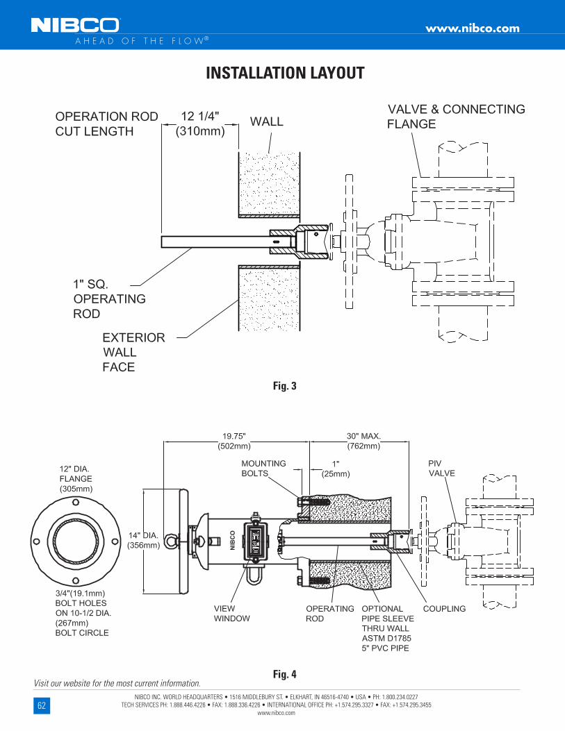
62NIBCO INC. WORLD HEADQUARTERS • 1516 MIDDLEBURY ST. • ELKHART, IN 46516-4740 • USA • PH: 1.800.234.0227
TECH SERVICES PH: 1.888.446.4226 • FAX: 1.888.336.4226 • INTERNATIONAL OFFICE PH: +1.574.295.3327 • FAX: +1.574.295.3455 www.nibco.com
Visit our website for the most current information.
www.nibco.com A H E A D O F T H E F L O W®
Fig . 3
Fig . 4
INSTALLATION LAYOUT
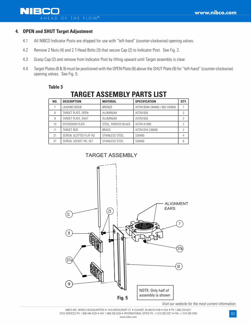
63NIBCO INC. WORLD HEADQUARTERS • 1516 MIDDLEBURY ST. • ELKHART, IN 46516-4740 • USA • PH: 1.800.234.0227
TECH SERVICES PH: 1.888.446.4226 • FAX: 1.888.336.4226 • INTERNATIONAL OFFICE PH: +1.574.295.3327 • FAX: +1.574.295.3455 www.nibco.com
Visit our website for the most current information.
www.nibco.com A H E A D O F T H E F L O W®
4 . OPEN and SHUT Target Adjustment
4 .1 All NIBCO Indicator Posts are shipped for use with “left-hand” (counter-clockwise) opening valves .
4 .2 Remove 2 Nuts (4) and 2 T-Head Bolts (3) that secure Cap (2) to Indicator Post . See Fig . 2 .
4 .3 Grasp Cap (2) and remove from Indicator Post by lifting upward until Target assembly is clear .
4 .4 Target Plates (8 & 9) must be positioned with the OPEN Plate (8) above the SHUT Plate (9) for “left-hand” (counter-clockwise) opening valves . See Fig . 5 .
TARGET ASSEMBLY PARTS LISTNO . DESCRIPTION MATERIAL SPECIFICATION QTY .
7 LEADING BOGIE BRONZE ASTM B584 C84400 / B62 C83600 1
8 TARGET PLATE, OPEN ALUMINUM ASTM B26 2
9 TARGET PLATE, SHUT ALUMINUM ASTM B26 2
10 EXTENSION PLATE STEEL, PAINTED BLACK ASTM A1008 2
11 TARGET ROD BRASS ASTM B16 C36000 2
21 SCREW, SLOTTED FLAT HD . STAINLESS STEEL S30400 4
37 SCREW, SOCKET HD . SET STAINLESS STEEL S30400 6
Table 3
Fig . 5
NOTE: Only half of assembly is shown

64NIBCO INC. WORLD HEADQUARTERS • 1516 MIDDLEBURY ST. • ELKHART, IN 46516-4740 • USA • PH: 1.800.234.0227
TECH SERVICES PH: 1.888.446.4226 • FAX: 1.888.336.4226 • INTERNATIONAL OFFICE PH: +1.574.295.3327 • FAX: +1.574.295.3455 www.nibco.com
Visit our website for the most current information.
www.nibco.com A H E A D O F T H E F L O W®
4 .5 Position OPEN Target Plates (8) so they are in the full upward position for “left-hand” (counter-clockwise) opening valves . Secure OPEN Target Plates (8) by tightening Screws (37a) . See Fig . 6 .
4 .6 Determine the number of turns required to fully open the valve . See Table 1 for NIBCO valves . You should always confirm actual turns required to open the valve by counting them .
4 .7 Using Table 6, choose the closest “Number of Turns to Open Valve” and the corresponding “Distance Between Targets” dimension “X” .
4 .8 Measure and position both SHUT Target Plates (9) at dimension “X” from OPEN Target Plates (8) . See Fig . 6 .
4 .9 Secure both SHUT Target Plates (9) by tightening Screws (37a) with an Allen wrench .
NUMBER OF TURNS TO OPEN
VALVE
DISTANCE BETWEEN TARGETS
X
INCH MM
10 0 .000 0 .0
11 0 .050 1 .3
12 0 .150 3 .8
13 0 .250 6 .4
14 0 .350 8 .9
15 0 .450 11 .4
16 0 .550 14 .0
17 0 .650 16 .5
18 0 .750 19 .1
19 0 .850 21 .6
20 0 .950 24 .1
21 1 .050 26 .7
22 1 .150 29 .2
23 1 .250 31 .8
NUMBER OF TURNS TO OPEN
VALVE
DISTANCE BETWEEN TARGETS
X
INCH MM
24 1 .350 34 .3
25 1 .450 36 .8
26 1 .550 39 .4
27 1 .650 41 .9
28 1 .750 44 .5
29 1 .850 47 .0
30 1 .950 49 .5
31 2 .050 52 .1
32 2 .150 54 .6
33 2 .250 57 .2
34 2 .350 59 .7
35 2 .450 62 .2
36 2 .550 64 .8
37 2 .650 67 .3
NUMBER OF TURNS TO OPEN
VALVE
DISTANCE BETWEEN TARGETS
X
INCH MM
38 2 .750 69 .9
39 2 .850 72 .4
40 2 .950 74 .9
41 3 .050 77 .5
42 3 .150 80 .0
43 3 .250 82 .6
44 3 .350 85 .1
45 3 .450 87 .6
46 3 .550 90 .2
47 3 .650 92 .7
48 3 .750 95 .3
49 3 .850 97 .8
50 3 .950 100 .3
51 4 .050 102 .9
ADJUSTMENT OF TARGET PLATESTable 4

65NIBCO INC. WORLD HEADQUARTERS • 1516 MIDDLEBURY ST. • ELKHART, IN 46516-4740 • USA • PH: 1.800.234.0227
TECH SERVICES PH: 1.888.446.4226 • FAX: 1.888.336.4226 • INTERNATIONAL OFFICE PH: +1.574.295.3327 • FAX: +1.574.295.3455 www.nibco.com
Visit our website for the most current information.
www.nibco.com A H E A D O F T H E F L O W®
POSITIONING OF OPEN TARGET PLATES FOR VIEW WINDOW
STANDARD TARGET LOCATION FOR “LEFT-HAND”
(COUNTER-CLOCKWISE) OPENING VALVES
Fig . 6 Fig . 7
6 . Positioning of Targets in View Window
6 .1 Rotate Square Operating Stem (5) positioning the center of the OPEN Target Plate (8) until it is located 6¾” from the inside lip of Cap (2) . See Fig . 7 .
6 .2 Verify that the valve is in full OPEN position .
6 .3 Reinstall the Cap (2) & Target assembly into the Upper Body (1) making sure both alignment ears on bronze Leading Boogie (7) straddle the guides cast on the inside of the Upper Body . See Fig . 2 .
6 .4 Reinstall 2 T-Head Bolts (3) in Cap and secure with 2 Nuts (4) .
6 .5 Check to assure that the OPEN Target Plate (8) is centered in both sides of the view window .

66NIBCO INC. WORLD HEADQUARTERS • 1516 MIDDLEBURY ST. • ELKHART, IN 46516-4740 • USA • PH: 1.800.234.0227
TECH SERVICES PH: 1.888.446.4226 • FAX: 1.888.336.4226 • INTERNATIONAL OFFICE PH: +1.574.295.3327 • FAX: +1.574.295.3455 www.nibco.com
Visit our website for the most current information.
www.nibco.com A H E A D O F T H E F L O W®
NO . DESCRIPTION PART NO .
3 T-HEAD BOLT NP1AU10
12 VIEW WINDOW NP1AU06
13 WINDOW GASKET NP1AU09
14 WINDOW GUARD NP1AU07
15 HANDWHEEL NP2AW31
NO . DESCRIPTION PART NO .
24 COTTER PIN NP1AU21
25 OPERATING ROD COUPLING NP1AU22
26 OPERATING ROD 36" NP2AW16
26 OPERATING ROD 72" NP1AU16
26 OPERATING ROD 90" NP1AU16E
REPAIR PARTS WALL MOUNT STYLETable 5
7 . Operation
7 .1 The post indicator valve (PIV) can be opened or shut by rotating Handwheel (15) in the desired direction . To open the valve, turn in the counter-clockwise direction as indicated on Cap (2) . To shut the valve, turn in the clockwise direction . See Fig . 2 .
7 .2 The Target Plates (8) (9) can be visually checked in the view windows to determine if PIV is open or shut .
7 .3 After installation, the PIV should be cycled to the full shut position and both view windows should be visually inspected to assure the SHUT target plates are centered . The PIV should then be cycled to the full open position and both view windows should be visually inspected to assure the OPEN target plates are centered .
7 .4 Valve position can be secured by placing a customer supplied chain through U-bolt (23), and Handwheel (15) . A customer supplied lock can be installed into the chain and U-bolt securing Handwheel, preventing valve operation .
7 .5 NIBCO Indicator Posts have provisions to add a Security Wire thru the Cap T-bolts (3) and Operating Stem (5) to prevent valve operation .
8 . Maintenance
8 .1 Lubrication should be added to oil hole located in top of Operating Stem (5) on an annual basis . Note: it is necessary to remove Eyebolt (16), Washer (17), and Handwheel (15) to expose the oil hole .
8 .2 Periodic visual inspection is recommended .
8 .3 Exercising (cycling) of the valve to assure proper function is recommended .
9 . Repair Parts
9 .1 Some specialty components are available for replacement if needed . See Table 5 .
9 .2 Common fasteners such as nuts, bolts, and washers are available at your local hardware .

67NIBCO INC. WORLD HEADQUARTERS • 1516 MIDDLEBURY ST. • ELKHART, IN 46516-4740 • USA • PH: 1.800.234.0227
TECH SERVICES PH: 1.888.446.4226 • FAX: 1.888.336.4226 • INTERNATIONAL OFFICE PH: +1.574.295.3327 • FAX: +1.574.295.3455 www.nibco.com
Visit our website for the most current information.
www.nibco.com A H E A D O F T H E F L O W®
TS-2M Replacement InstructionsCSA Approved • SEV Approved • UL Listed • FM Approved
Factory Installed Supervisory SwitchesFor Figure No . 505 Ball Valve
Supervisory / tamper switch voltage and current ratings: Supervisory Switch - for valve position supervisory / tamper indication used with U .L . listed fire alarm control panel - two (2) leads per terminal; 6 amps @ 125 volts AC 60 Hz, or 1 amp @ 28 volts DC non-inductive . See Note 2 . Auxiliary Switch - auxiliary switch which may be connected per authority having jurisdiction of auxiliary devices - one (1) lead per terminal; 6 amps @ 125 volts AC 60 Hz, or 1 amp @ 28 volts DC non-inductive .
NOTES: 1) Circuit shown in set condition when valve is in non-open position . 2) For connection to system meeting current N .F .P .A requirements, leads A," "B," "C," and "D" are used . Connections "E," "F," and "G" are for proprietary use only - NOT intended for electrical supervision . Please consult local authority for acceptable connection . 3) Refer to N .F .P .A . 13 (Installation of Sprinkler Systems), 70 (National Electrical Code), 72 (Installation, Maintenance, and Use of Protective Signaling Systems), and any other applicable standards prior to installation . 4) Supervisory switch is preset and tested in accordance with all applicable agency requirements at the factory . No adjustment is possible once the valve is assembled . 5) All lead wires are 18 AWG, 18 inches long and exit the actuator housing through a single threaded hole designed for ¹⁄₂-inch conduit fittings .
Revised 11/13/2017

68NIBCO INC. WORLD HEADQUARTERS • 1516 MIDDLEBURY ST. • ELKHART, IN 46516-4740 • USA • PH: 1.800.234.0227
TECH SERVICES PH: 1.888.446.4226 • FAX: 1.888.336.4226 • INTERNATIONAL OFFICE PH: +1.574.295.3327 • FAX: +1.574.295.3455 www.nibco.com
Visit our website for the most current information.
www.nibco.com A H E A D O F T H E F L O W® Revised 11/16/2021
TS4 Replacement Instructions
Tools required: 1/8" Allen wrench 5/32" Socket Pin Head Wrench (2" - 8") 3/16" Socket Pin Head Wrench (10" - 12") 9/16" Socket Wrench (2" - 8") 3/4" Socket Wrench (10" - 12") 3/16" Standard Screwdriver
1 . Remove flag (A) by backing out (approximately 2 turns) hex socket set screw (B) .
2 . Remove one socket pin head screw (C), three socket head bolts (D) and gear operator cover (E) .
3 . Remove two screws holding switch assembly into housing, and one screw holding ground wire to housing and remove switch assembly .
4 . Feed electrical wires of new switch assembly through hole in rear of housing . Put new switch assembly (F) into gear case with actuating arms against quadrant gear . Reinstall hold down screws and ground wire to housing .
• Before installing cover plate, a continuity test should be performed to assure that switches are properly set .
5 . Reinstall cover plate . (D)
6 . Reinstall flag . (A)
7 . Use and connection of auxiliary switch to be reviewed and accepted by local authority having jurisdicition .
*Instructions are same regardless of valve end connections .
Note: Reference Section VI of the Rubber-Seated Butterfly Valve O&M Manual .
CSA Approved • UL Listed • FM Approved
Factory Installed Supervisory SwitchesFor Figure No . GD-4765-8N/GD-6765-8N Grooved Butterfly Valves and WD/LD-3510-8, 2002 and later Wafer/Lug Butterfly Valves
NOTE: Grooved end valve shown for illustration purposes only.
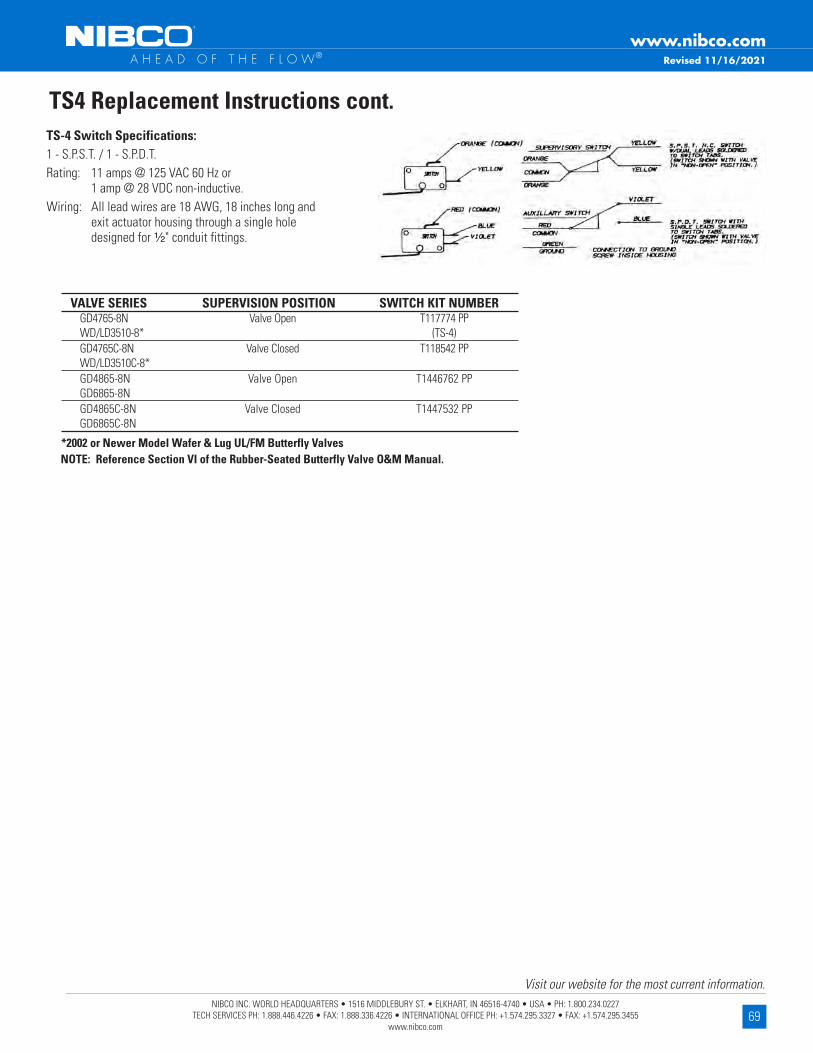
69NIBCO INC. WORLD HEADQUARTERS • 1516 MIDDLEBURY ST. • ELKHART, IN 46516-4740 • USA • PH: 1.800.234.0227
TECH SERVICES PH: 1.888.446.4226 • FAX: 1.888.336.4226 • INTERNATIONAL OFFICE PH: +1.574.295.3327 • FAX: +1.574.295.3455 www.nibco.com
Visit our website for the most current information.
www.nibco.com A H E A D O F T H E F L O W®
TS4 Replacement Instructions cont .
NOTE: Reference Section VI of the Rubber-Seated Butterfly Valve O&M Manual .
VALVE SERIES SUPERVISION POSITION SWITCH KIT NUMBER GD4765-8N Valve Open T117774 PP WD/LD3510-8* (TS-4) GD4765C-8N Valve Closed T118542 PP WD/LD3510C-8* GD4865-8N Valve Open T1446762 PP GD6865-8N GD4865C-8N Valve Closed T1447532 PP GD6865C-8N
*2002 or Newer Model Wafer & Lug UL/FM Butterfly Valves
TS-4 Switch Specifications: 1 - S .P .S .T . / 1 - S .P .D .T . Rating: 11 amps @ 125 VAC 60 Hz or 1 amp @ 28 VDC non-inductive . Wiring: All lead wires are 18 AWG, 18 inches long and exit actuator housing through a single hole designed for ¹⁄₂" conduit fittings .
Revised 11/16/2021

70NIBCO INC. WORLD HEADQUARTERS • 1516 MIDDLEBURY ST. • ELKHART, IN 46516-4740 • USA • PH: 1.800.234.0227
TECH SERVICES PH: 1.888.446.4226 • FAX: 1.888.336.4226 • INTERNATIONAL OFFICE PH: +1.574.295.3327 • FAX: +1.574.295.3455 www.nibco.com
Visit our website for the most current information.
www.nibco.com A H E A D O F T H E F L O W®
Properties of Valve Materials
Revised 11/13/2017
OTHER MANGA- MOLYB- ASTM ALLOY CARBON CHROME COBALT COPPER IRON LEAD NESE DENUM ALLOY NO. DESIGNATION AL C Cr Co Cu Fe Pb Mn Mo
Commercial Aluminum 380 SC 84 A UNS A38000 87.0 1.0 1.3 .35 (modified)
Free Cutting Brass B16 UNS C36000 61.5 3.0
Navy "M" (Steam Bronze) B61 UNS C92200 .005 88.0 .25 1.5
Composition Bronze (Ounce Metal) B62 UNS C83600 .005 85.0 .30 5.0
Copper-Silicon Alloy B B98/B99 UNS C65100 96.0 .8 .05 .7
Forging Brass B124 UNS C37700 60.0 .3 2.0
Forging Brass B283 UNS C37700 58.0 .3 2.5
Brass Wire (Red Brass) B134 UNS C23000 85.0 .05 .05
Leaded Red Brass B140 UNS C31400 89.0 .10 1.9
Aluminum Bronze (Cast) B148 UNS C95400 11.0 85.0 4.0
Aluminum Bronze (Rod) B150 UNS C64200 7.0 91.0 .30 .05 .10
Silicon Red Brass B371 UNS C69400 81.5 .20 .30
Leaded Semi-Red Brass B584 UNS C84400 .005 81.0 .40 7.0
Leaded Red Brass UNS C84500 .005 78.0 .40 7.0
Leaded Nickel Bronze B584 UNS C97600 64.0 4.0
Copper
(Wrot) B 75 UNS C12200 99.9
Gray Iron A126 Class B
3% Ni Gray Iron A126 Class B (modified)
Austenitic Gray Iron (Ni-Resist) A436 Type 2 3.00 2.0 .5 1.0
Ductile Iron (Ferritic) A395 3.20
Austenitic Ductile Iron (Ductile) A536 65-45-12 (Ductile) A536 80-55-06 (Ni-Resist) A439 D2C 2.9 .5 2.4 1.0
NOMINAL OR MAXIMUM CHEMICAL COMPOSITION
Iro
nC
op
per
Bro
nze
& B
rass
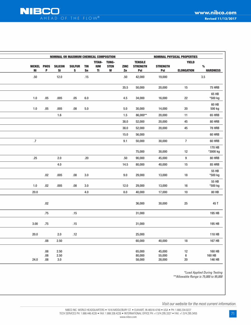
71NIBCO INC. WORLD HEADQUARTERS • 1516 MIDDLEBURY ST. • ELKHART, IN 46516-4740 • USA • PH: 1.800.234.0227
TECH SERVICES PH: 1.888.446.4226 • FAX: 1.888.336.4226 • INTERNATIONAL OFFICE PH: +1.574.295.3327 • FAX: +1.574.295.3455 www.nibco.com
Visit our website for the most current information.
www.nibco.com A H E A D O F T H E F L O W®
TITAN- TUNG- TENSILE YIELD NICKEL PHOS SILICON SULFUR TIN IUM STEN ZINC STRENGTH STRENGTH % Ni P Si S Sn Ti W Zn Psi Psi ELONGATION HARDNESS
.50 12.0 .15 .50 42,000 19,000 3.5
35.5 50,000 20,000 15 75 HRB
65 HB 1.0 .05 .005 .05 6.0 4.5 34,000 16,000 22 *500 kg
60 HB 1.0 .05 .005 .08 5.0 5.0 30,000 14,000 20 500 kg
1.6 1.5 86,000** 20,000 11 65 HRB
38.0 52,000 20,000 45 80 HRB
38.0 52,000 20,000 45 78 HRB
15.0 56,000 60 HRB
.7 9.1 50,000 30,000 7 60 HRB
170 HB 75,000 30,000 12 *3000 kg
.25 2.0 .20 .50 90,000 45,000 9 80 HRB
4.0 14.5 80,000 40,000 15 85 HRB
55 HB .02 .005 .08 3.0 9.0 29,000 13,000 18 *500 kg
55 HB 1.0 .02 .005 .08 3.0 12.0 29,000 13,000 16 *500 kg
20.0 4.0 8.0 40,000 17,000 10 80 HB
.02 36,000 30,000 25 45 T
.75 .15 31,000 195 HB
3.00 .75 .15 31,000 195 HB
20.0 2.0 .12 25,000 118 HB
.08 2.50 60,000 40,000 18 167 HB
.08 2.50 65,000 45,000 12 160 HB .08 2.50 80,000 55,000 6 160 HB 24.0 .08 3.0 58,000 28,000 20 146 HB
*Load Applied During Testing **Allowable Range is 75,000 to 95,000
NOMINAL OR MAXIMUM CHEMICAL COMPOSITION NOMINAL PHYSICAL PROPERTIES
Revised 11/13/2017
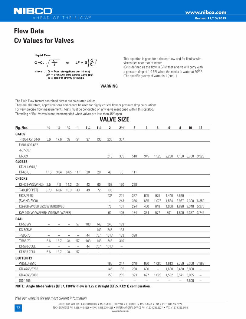
72NIBCO INC. WORLD HEADQUARTERS • 1516 MIDDLEBURY ST. • ELKHART, IN 46516-4740 • USA • PH: 1.800.234.0227
TECH SERVICES PH: 1.888.446.4226 • FAX: 1.888.336.4226 • INTERNATIONAL OFFICE PH: +1.574.295.3327 • FAX: +1.574.295.3455 www.nibco.com
Visit our website for the most current information.
www.nibco.com A H E A D O F T H E F L O W®
WARNING
The Fluid Flow factors contained herein are calculated values . They are, therefore, approximations and cannot be used for highly critical flow or pressure drop calculations . For very precise flow measurements, tests must be conducted on any valve mentioned within this catalog . Throttling of Ball Valves is not recommended when valves are less than 45o open .
Fig . Nos . ¹⁄₄ ¹⁄₂ ³⁄₄ 1 1¹⁄₄ 1¹⁄₂ 2 2¹⁄₂ 3 4 5 6 8 10 12
GATES T-103-HC/104-0 5 .6 17 .6 32 54 97 135 230 337
F-607-609-637 -667-697
M-609 215 335 510 945 1,525 2,250 4,150 6,700 9,925
GLOBES KT-211-WUL/ KT-65-UL 1 .16 3 .64 6 .65 11 .1 20 28 48 70 111
CHECKS
KT-403-W(SWING) 2 .5 4 .8 14 .3 24 43 60 102 150 238
T-480(POPPET) 3 .70 6 .86 16 .3 30 49 72 130
F938/F968 137 221 327 605 975 1,440 2,670 --- --- (SWING F908) --- 243 356 665 1,073 1,584 2,937 4,300 6,350
KG-900-W/350 G920W (GROOVED) 76 161 224 400 648 1,060 1,890 3,340 5,270
KW-900-W (WAFER)/ W920W (WAFER) 60 105 184 354 577 801 1,500 2,357 3,742
BALL KT-505W --- --- --- 57 103 143 245 183
KG-505W --- --- --- --- --- 143 245 183
T-580-70 --- --- --- --- 44 76 .1 101 .4 183 390
T-585-70 5 .6 18 .7 34 57 103 143 245 310
KT-580-70UL --- --- --- --- 44 76 .1 101 .4 ---
KT-585-70UL 5 .6 18 .7 34 57 --- --- --- ---
BUTTERFLY WD/LD-3510 166 247 340 660 1,080 1,613 3,759 5,300 7,969
GD-4765/6765 145 195 290 600 --- 1,600 3,450 5,800 ---
GD-4865/6865 158 235 323 627 1,026 1,532 3,571 5,035 ---
GD-1765 --- --- --- --- --- --- --- 5,800 ---
NOTE: Angle Globe Valves (KT67, T301W) flow is 1 .25 x straight (KT65, KT211) configuration .
VALVE SIZE
Flow DataCv Values for Valves
This equation is good for turbulent flow and for liquids with viscosities near that of water . (Cv is defined as the flow in GPM that a valve will carry with a pressure drop of 1 .0 PSI when the media is water at 60o F .) (The specific gravity of water is 1 (one) . )
Revised 11/15/2019

73NIBCO INC. WORLD HEADQUARTERS • 1516 MIDDLEBURY ST. • ELKHART, IN 46516-4740 • USA • PH: 1.800.234.0227
TECH SERVICES PH: 1.888.446.4226 • FAX: 1.888.336.4226 • INTERNATIONAL OFFICE PH: +1.574.295.3327 • FAX: +1.574.295.3455 www.nibco.com
Visit our website for the most current information.
www.nibco.com A H E A D O F T H E F L O W®
Gate Valve Dimensions forSupervisory Switch Application
Stem Dia . and Thread Valve Size A B C D E F G Pitch Thds/in Lead Type
T-104-O ¹⁄₂ 0 .33 1 .50 0 .28 --- --- 0 .63 --- .08 0 .44-12 .00 Dble . 60° STUB
³⁄₄ 0 .33 1 .50 0 .31 --- --- 0 .63 --- .08 0 .44-12 .00 Dble . 60° STUB
1 0 .70 1 .63 0 .31 --- --- 0 .75 --- .08 0 .50-12 .00 Dble . 60° STUB
1¹⁄₄ 0 .35 2 .63 0 .31 --- --- 0 .81 --- .11 0 .56-9 .00 Dble . 60° STUB
1¹⁄₂ 0 .35 2 .63 0 .31 --- --- 0 .88 --- .11 0 .56-9 .00 Dble . 60° STUB
2 0 .84 2 .50 0 .44 --- --- 0 .88 --- .13 0 .69-8 .00 Dble . 60° STUB
F-607-OTS 2¹⁄₂ 1 .13 2 .38 0 .88 0 .44 0 .44 1 .19 0 .38 .17 0 .75-6 .00 Dble . STUB ACME
3 1 .75 2 .50 0 .88 0 .50 0 .38 1 .63 0 .38 .17 0 .75-6 .00 Dble . STUB ACME
4 1 .63 3 .13 1 .50 0 .75 0 .75 2 .00 0 .50 .25 1 .00-4 .00 Dble . STUB ACME
5 2 .50 3 .38 1 .50 0 .75 0 .75 2 .25 0 .75 .25 1 .00-4 .00 Dble . STUB ACME
6 2 .50 3 .38 1 .50 0 .75 0 .75 2 .25 0 .75 .25 1 .13-4 .00 Dble . STUB ACME
8 4 .75 4 .50 1 .63 0 .75 0 .88 2 .03 0 .75 .25 1 .25-4 .00 Dble . STUB ACME
10 6 .63 4 .50 2 .25 1 .25 1 .00 3 .00 0 .75 .33 1 .38-3 .00 Sgle . STUB ACME
12 6 .63 4 .50 2 .25 1 .00 1 .00 3 .00 0 .75 .33 1 .50-3 .00 Sgle . . STUB ACME
F-667-O/F-697-0 2¹⁄₂ 1 .13 2 .25 0 .50 --- --- 2 .00 --- .17 0 .75-6 .00 Dble . STUB ACME
3 1 .56 2 .75 1 .00 0 .50 0 .50 2 .25 0 .50 .25 1 .00-4 .00 Dble . STUB ACME
4 1 .63 3 .75 1 .50 0 .75 0 .75 2 .00 0 .50 .25 1 .13-4 .00 Dble . STUB ACME
5 1 .25 4 .50 1 .63 0 .75 0 .88 3 .00 0 .75 .25 1 .25-4 .00 Dble . STUB ACME
6 1 .25 4 .38 1 .63 0 .75 0 .88 2 .88 0 .75 .33 1 .38-3 .00 Dble . STUB ACME
8 7 .63 4 .50 2 .44 1 .38 1 .63 4 .75 0 .75 .33 1 .50-3 .00 Dble . STUB ACME
10 8 .25 4 .50 2 .50 1 .75 0 .75 4 .75 0 .75 .50 1 .88-2 .00 Sgle . STUB ACME
12 8 .88 4 .50 2 .50 1 .75 0 .75 4 .00 0 .75 .50 1 .88-2 .00 Sgle . STUB ACME
F-607-RW 2¹⁄₂ 1 .55 2 .56 0 .76 0 .45 0 .31 1 .43 0 .31 .16 0 .79 X 6 .25 Sgle . ACME
3 2 .04 2 .56 0 .75 0 .43 0 .31 1 .42 0 .31 .16 0 .79 X 6 .25 Sgle . ACME
4 2 .55 2 .95 0 .79 0 .39 0 .39 1 .67 0 .39 .20 0 .98 X 5 .00 Sgle . ACME
6 4 .04 3 .54 0 .81 0 .38 0 .43 1 .73 0 .43 .20 1 .70 X 5 .00 Sgle . ACME
8 6 .04 3 .98 0 .92 0 .45 0 .47 2 .11 0 .47 .24 1 .26 X 4 .20 Sgle . ACME
10 7 .84 4 .33 0 .99 0 .44 0 .55 2 .52 0 .55 .24 1 .42 X 4 .20 Sgle . ACME
12 9 .84 4 .33 0 .94 0 .39 0 .55 2 .48 0 .55 .24 1 .57 X 3 .60 Sgle . ACMENote: All valves have left hand thread .
Revised 11/13/2017
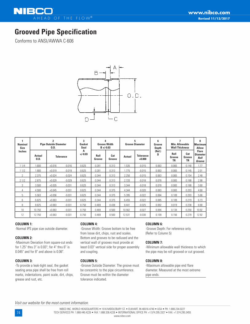
74NIBCO INC. WORLD HEADQUARTERS • 1516 MIDDLEBURY ST. • ELKHART, IN 46516-4740 • USA • PH: 1.800.234.0227
TECH SERVICES PH: 1.888.446.4226 • FAX: 1.888.336.4226 • INTERNATIONAL OFFICE PH: +1.574.295.3327 • FAX: +1.574.295.3455 www.nibco.com
Visit our website for the most current information.
www.nibco.com A H E A D O F T H E F L O W®
Grooved Pipe SpecificationConforms to ANSI/AWWA C-606
COLUMN 1: -Normal IPS pipe size outside diameter . COLUMN 2: -Maximum Deviation from square-cut ends for 1 .25" thru 3" is 0 .03"; for 4" thru 6" is 0 .045" and for 8" and above is 0 .06" . COLUMN 3: -To provide a leak-tight seal, the gasket seating area pipe shall be free from roll marks, indentations, paint scale, dirt, chips, grease and rust, etc .
COLUMN 4: -Groove Width: Groove bottom to be free from loose dirt, chips, rust and scales . Bottom and grooves to be radiused and the vertical wall of grooves must provide at least 0 .03" vertical side for proper assembly and coupling . COLUMN 5: -Groove Outside Diameter: The groove must be concentric to the pipe circumference . Groove must be within the diameter tolerance indicated .
COLUMN 6: -Groove Depth: For reference only . (Refer to Column 5) COLUMN 7: -Minimum allowable wall thickness to which the pipe may be roll grooved or cut grooved . COLUMN 8: -Maximum allowable pipe end flare diameter . Measured at the most extreme pipe ends .
1 1/4 1 .600 +0 .016 -0 .016 0 .625 0 .281 0 .313 1 .535 -0 .015 0 .063 0 .065 0 .140 1 .77
1 1/2 1 .900 +0 .019 -0 .019 0 .625 0 .281 0 .313 1 .775 -0 .015 0 .063 0 .065 0 .145 2 .01
2 2 .375 +0 .024 -0 .024 0 .625 0 .344 0 .313 2 .250 -0 .015 0 .063 0 .065 0 .154 2 .48
2 1/2 2 .875 +0 .029 -0 .029 0 .625 0 .344 0 .313 2 .720 -0 .018 0 .078 0 .083 0 .188 2 .98
3 3 .500 +0 .035 -0 .031 0 .625 0 .344 0 .313 3 .344 -0 .018 0 .078 0 .083 0 .188 3 .60
4 4 .500 +0 .045 -0 .031 0 .625 0 .344 0 .375 4 .344 -0 .020 0 .083 0 .083 0 .203 4 .60
5 5 .563 +0 .056 -0 .031 0 .625 0 .344 0 .375 5 .395 -0 .022 0 .084 0 .109 0 .203 5 .66
6 6 .625 +0 .063 -0 .031 0 .625 0 .344 0 .375 6 .455 -0 .022 0 .085 0 .109 0 .219 6 .73
8 8 .625 +0 .063 -0 .031 0 .750 0 .469 0 .438 8 .441 -0 .025 0 .092 0 .019 0 .238 8 .80
10 10 .750 +0 .063 -0 .031 0 .750 0 .469 0 .500 10 .562 -0 .027 0 .094 0 .134 0 .250 10 .92
12 12 .750 +0 .063 -0 .031 0 .750 0 .469 0 .500 12 .531 -0 .030 0 .109 0 .156 0 .279 12 .92
Revised 11/13/2017
1 Nominal
Size Inches
2 Pipe Outside Diameter
O .D .
4 Groove Width
B +/-0 .03
5 Groove Diameter
7 Min . Allowable Wall Thickness
3 Gasket
Seal A
+/-0 .03
6 Groove Depth (Ref .)
D
8 Maximum
Allow Flare
Diameter Roll
Groove
Actual O .D .
Tolerance Roll Groove
Cut Groove
Actual Tolerance +0 .000
Roll Groove
TR
Cut Groove
TR
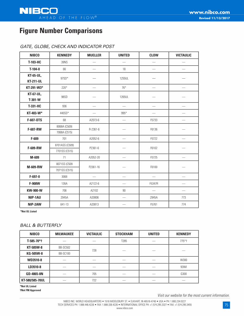
75NIBCO INC. WORLD HEADQUARTERS • 1516 MIDDLEBURY ST. • ELKHART, IN 46516-4740 • USA • PH: 1.800.234.0227
TECH SERVICES PH: 1.888.446.4226 • FAX: 1.888.336.4226 • INTERNATIONAL OFFICE PH: +1.574.295.3327 • FAX: +1.574.295.3455 www.nibco.com
Visit our website for the most current information.
www.nibco.com A H E A D O F T H E F L O W®
Figure Number Comparisons
GATE, GLOBE, CHECK AND INDICATOR POST
*Not UL Listed
NIBCO KENNEDY MUELLER UNITED CLOW VICTAULIC
T-103-HC 39NS — — — —
T-104-0 66 — 18 — —
KT-65-UL,
KT-211-UL97SD* — 1255UL — —
KT-291-W3* 220* — 76* — —
KT-67-UL,
T-301-W98SD — 1265UL — —
T-331-HC 936 — — — —
KT-403-W* 440SD* — 995* — —
F-607-OTS 68 A2073-6 — F5733 —
F-607-RW8068A (C509)
R-2361-6 — F6136 —7068A (C515)
F-609 701 A2052-6 — F5722 —
F-609-RW8701ASS (C509)
P2361-6 — F6102 —7701SS (C515)
M-609 71 A2052-20 — F5725 —
M-609-RW8071SS (C509
P2361-16 — F6100 —7071SS (C515)
F-697-0 3068 — — — —
F-908W 126A A2122-6 — F5347R —
KW-900-W 706 A2102 90 — —
NIP-1AU 2945A A20806 — 2945A 773
NIP-2AW 641-13 A20813 — F5761 774
*Not UL Listed†Not FM Approved
NIBCO MILWAUKEE VICTAULIC STOCKHAM UNITED KENNEDY
T-585-70*† — — T285 — 775*†
KT-505W-8 BB-SC502728 — — —
KG-505W-8 BB-SC100
WD3510-8 — — — — W300
LD3510-8 — — — — 93WI
GD-4865-8N — 705 — — G300
KT-580/585-70UL — 722 — — —
BALL & BUTTERFLY
Revised 11/13/2017

76NIBCO INC. WORLD HEADQUARTERS • 1516 MIDDLEBURY ST. • ELKHART, IN 46516-4740 • USA • PH: 1.800.234.0227
TECH SERVICES PH: 1.888.446.4226 • FAX: 1.888.336.4226 • INTERNATIONAL OFFICE PH: +1.574.295.3327 • FAX: +1.574.295.3455 www.nibco.com
Visit our website for the most current information.
www.nibco.com A H E A D O F T H E F L O W®
Schematic courtesy of Rick Perella
A Typical Fire ProtectionSprinkler System
Revised 11/13/2017

77NIBCO INC. WORLD HEADQUARTERS • 1516 MIDDLEBURY ST. • ELKHART, IN 46516-4740 • USA • PH: 1.800.234.0227
TECH SERVICES PH: 1.888.446.4226 • FAX: 1.888.336.4226 • INTERNATIONAL OFFICE PH: +1.574.295.3327 • FAX: +1.574.295.3455 www.nibco.com
Visit our website for the most current information.
www.nibco.com A H E A D O F T H E F L O W®
REPLACEMENT HANDWHEELS F607RW & F607RWS GATE VALVES
VALVE SIZE F607RWS F607RW
2½"T1447559 PP T117454 PP
3"
4" T1447560 PP T117422 PP
6" T1447561 PP T117427 PP
8" T1447562 PP T117400 PP
10" T117485 PP
12" T117371 PP
REPLACEMENT HANDWHEEL NUTSF607RW & F607RWS GATE VALVES
VALVE SIZEF607RWS F607RW
MATERIAL NO NUT OD X TK THREAD SIZE MATERIAL NO NUT OD X TK THREAD SIZE
2½"T1470614 PP 52 X 10 M30 X 1 .5 T1098244 PP 52 X 10 M33 X 1 .5
3"
4"T1470615 PP 58 x 10 M39 X 1 .5 USE T1470616 PP 68 X 10 M45 X 1 .5
6"
8" T1470616 PP 68 x 10 M45 x 1 .5T1470616 PP 72 X 12 M48 X 1 .5
10" T1471723 PP 72 x 12 M48 x 1 .5
12" T1470617 PP 78 X 12 M52 X 1 .5 T1470617 PP 78 X 12 M52 X 1 .5
14"T1470618 PP 90 X 12 M60 X 2
16"

78NIBCO INC. WORLD HEADQUARTERS • 1516 MIDDLEBURY ST. • ELKHART, IN 46516-4740 • USA • PH: 1.800.234.0227
TECH SERVICES PH: 1.888.446.4226 • FAX: 1.888.336.4226 • INTERNATIONAL OFFICE PH: +1.574.295.3327 • FAX: +1.574.295.3455 www.nibco.com
Visit our website for the most current information.
www.nibco.com A H E A D O F T H E F L O W®
Fire Protection Butterfly ValvesGear Operator Repair Parts
ITEMVALVE SIZE
VALVE ASSEMBLY
FIGURE NUMBER
BUSHING REFERENCE
NUMBER
BUSHING ASSEMBLY
PART NUMBER
DRIVE KEY PART
NUMBER
DRIVE KEY SIZE
DRIVE KEYMATERIAL
FLAG PART NUMBER (YELLOW)
HAND-WHEEL PART
NUMBER
HAND-WHEEL
PIN PART NUMBER
1 2" WD/LD 3510 01 T117725 PP T117850 PP 1/8" SQ X .38" LG BRASS T117865 PP T117122 PP T117877 PP
2 2½" & 3" WD/LD 3510 02 T117726 PP T117851 PP 1/8" SQ X .68" LG BRASS T117865 PP T117122 PP T117877 PP
3 2½" & 3" GD-4765/6765 02 T117726 PP T117850 PP 1/8" SQ X .38" LG BRASS T117865 PP T117122 PP T117877 PP
4 2½" & 3" GD-4865/6885 - T118778 PP T117852 PP 1/8" SQ X .44" LG STEEL T1446767 PP T1446759 PP INCLUDED
5 4" WD/LD 3510 03 T117727 PP T117852 PP 1/8" SQ X .44" LG STEEL T117865 PP T117122 PP T117877 PP
6 4" GD-4865/6885 - T118779 PP T117852 PP 1/8" SQ X .44" LG STEEL T1446767 PP T1446759 PP INCLUDED
7 4" & 5" GD-4765/6765 04 T117728 PP T117853 PP 1/8" SQ X .29" LG STEEL T117865 PP T117122 PP T117877 PP
8 5" & 6" WD/LD 3510 04 T117728 PP T117854 PP 1/8" SQ X .41" LG STEEL T117865 PP T117122 PP T117877 PP
9 6" GD-4765/6765 05 T117729 PP T117856 PP 1/8" SQ X .91" LG STEEL T117865 PP T117122 PP T117877 PP
10 6" & 8" GD-4865/6885 - T118780 PP T117856 PP 1/8" SQ X .91" LG STEEL T1446767 PP T1446760 PP INCLUDED
11 8" WD/LD 3510 05 T117729 PP T117856 PP 1/8" SQ X .91" LG STEEL T117865 PP T117123 PP T117877 PP
12 8" GD-4765/6765 05 T117729 PP T117856 PP 1/8" SQ X .91" LG STEEL T117865 PP T117123 PP T117877 PP
13 10" WD/LD 3510 06 T117730 PP T117858 PP 3/16" SQ X 1.00 LG STEEL T117865 PP T118472 PP T117877 PP
14 10" GD-1765/6765 07 T117731 PP T117858 PP 3/16" SQ X 1.00 LG STEEL T117865 PP T118472 PP T117877 PP
15 10" GD-4865/6885 - T118781 PP T117858 PP 3/16" SQ X 1.00 LG STEEL T1446767 PP T1446760 PP INCLUDED
16 12" WD/LD 3510 07 T117731 PP T117858 PP 3/16" SQ X 1.00 LG STEEL T117865 PP T118472 PP T117877 PP
Notes: 1 . T117865 PP flag is painted yellow . For red painted flag use part number T1414066 PP .
2 . T1446767 PP flag is painted yellow . For red painted flag use part number T1446768 PP . 3 . Thread cutting screw T1430191 PP is included with T1446767 PP & T1446768 flags . 4 . Handwheel pin is included with T1446759 PP & T1446760 PP handwheels .
Supervisory Switches
ITEMVALVE ASSEMBLY SERIES
FIGURE NUMBERSUPERVISION
POSITIONSWITCH KIT
PART NUMBER
17 WL/LD3510-8* & GD4765-8N VALVE OPEN T117774 PP (TS-4)
* 2002 OR NEWER MODEL WAFER & LUG UL/FM BUTTERFLY VALVES
18 WL/LD3510C-8* & GD4765C-8N VALVE CLOSED T118542 PP
19 GD4865-8N & GD6865-8N VALVE OPEN T1446762 PP
20 GD4865C-8N & GD6865C-8N VALVE CLOSED T1447532 PP
21 WL/LD3510-8* & GD4765-8N VALVE OPEN T118855 ASBLY FOR HARSH ENVIRONMENT SERVICE

79NIBCO INC. WORLD HEADQUARTERS • 1516 MIDDLEBURY ST. • ELKHART, IN 46516-4740 • USA • PH: 1.800.234.0227
TECH SERVICES PH: 1.888.446.4226 • FAX: 1.888.336.4226 • INTERNATIONAL OFFICE PH: +1.574.295.3327 • FAX: +1.574.295.3455 www.nibco.com
Visit our website for the most current information.
www.nibco.com A H E A D O F T H E F L O W®
Notes:

80NIBCO INC. WORLD HEADQUARTERS • 1516 MIDDLEBURY ST. • ELKHART, IN 46516-4740 • USA • PH: 1.800.234.0227
TECH SERVICES PH: 1.888.446.4226 • FAX: 1.888.336.4226 • INTERNATIONAL OFFICE PH: +1.574.295.3327 • FAX: +1.574.295.3455 www.nibco.com
Visit our website for the most current information.
www.nibco.com A H E A D O F T H E F L O W®
Notes:

81NIBCO INC. WORLD HEADQUARTERS • 1516 MIDDLEBURY ST. • ELKHART, IN 46516-4740 • USA • PH: 1.800.234.0227
TECH SERVICES PH: 1.888.446.4226 • FAX: 1.888.336.4226 • INTERNATIONAL OFFICE PH: +1.574.295.3327 • FAX: +1.574.295.3455 www.nibco.com
Visit our website for the most current information.
www.nibco.com A H E A D O F T H E F L O W®
Notes:

82NIBCO INC. WORLD HEADQUARTERS • 1516 MIDDLEBURY ST. • ELKHART, IN 46516-4740 • USA • PH: 1.800.234.0227
TECH SERVICES PH: 1.888.446.4226 • FAX: 1.888.336.4226 • INTERNATIONAL OFFICE PH: +1.574.295.3327 • FAX: +1.574.295.3455 www.nibco.com
Visit our website for the most current information.
www.nibco.com A H E A D O F T H E F L O W® Revised 11/22/2021
NIBCO INC. 125% LIMITED WARRANTY
Applicable to NIBCO Pressure Rated Metal Valves
NIBCO INC. warrants each NIBCO pressure rated metal valve (“Valves”) to be free from defects in materials and workmanship under normal use, service, and maintenance in accordance with the product specifications (including, but not limited to installation recom-mendations) for a period of five (5) years from the Warranty Commencement Date. The Warranty Commencement Date shall be the date upon which a Valve is installed.
NIBCO will repair or replace – at its option and at no charge –Valves that have been determined by NIBCO, or an authorized repre-sentative or agent thereof, to have failed solely because of a defect in materials or workmanship under normal use, service, and main-tenance during the warranty period. Replacements shall be shipped free of charge to the owner. In the event of the replacement of any Valve, NIBCO shall further pay the owner the greater of twenty-five (25%) percent of the price of the Valve according to the published suggested list price schedule of NIBCO in effect at the time of purchase, or ten ($10.00) dollars, to apply on the cost of the installation of said replacement Valve.
This limited warranty applies to all Valves installed, tested, applied, and used in accordance with NIBCO’s approved and published recommendations and instructions.
This warranty does not cover any failure or damage for or caused by:
1. any product, parts, or systems which are not manufactured or sold by NIBCO;2. any Valve which is used for purposes other than a purpose authorized by NIBCO;3. any Valve not installed, tested, applied, used, or maintained in accordance with NIBCO’s recommended installation guidelines
and instructions; 4. any Valve not installed or used in accordance with applicable codes;5. any damage caused by, contributed in whole or in part by, or resulting from, any of the following:
a. abuse, misuse, mishandling, alteration, tampering, neglect, or accidental damage such as, without limitation, vandalism;b. natural disasters, such as, without limitation, flooding, windstorm, and lightning;c. attachments or modifications not authorized by NIBCO;d. external, physical or chemical qualities, or an unsuitable or hostile environment,; e. any defects other than those in material or workmanship; orf. any other cause beyond the control of NIBCO.
NIBCO DISCLAIMS ANY AND ALL LIABILITY FOR ANY OTHER DIRECT OR INDIRECT, INCIDENTAL, OR CONSEQUENTIAL DAMAGES OF ANY KIND, INCLUDING BUT NOT LIMITED TO, ECONOMIC LOSS, LOSS OF BUSINESS, LOST PROFITS, PUNITIVE DAMAGES, MOLD INTRUSION, WATER DAMAGE, ETC.
Some states do not allow the exclusion or limitation of damages, so the above limitation or exclusion may not apply to you.
THIS WARRANTY IS THE ONLY WARRANTY FOR THE VALVES PROVIDED BY NIBCO, AND IS AND SHALL BE IN LIEU OF ANY AND ALL OTHER WARRANTIES, EXPRESSED OR IMPLIED, INCLUDING, BUT NOT LIMITED TO, AN IMPLIED WARRANTY OF MERCHANTABILITY OR FITNESS FOR A PARTICULAR PURPOSE, AND FOR ALL OTHER OBLIGATIONS OR LIABILITIES ON THE PART OF A MANUFACTURER. NO EMPLOYEE OF NIBCO, OR ANY OTHER DISTRIBUTOR, AGENT, OR OTHER PERSON OR BUSINESS, IS AUTHORIZED TO MAKE ANY OTHER WAR-RANTY ON BEHALF OF NIBCO.
Some states do not allow limitations on implied warranties, so the above limitation may not apply to you.
In the event any defect occurs which is believed to be covered by this warranty, NIBCO Technical Servic-es must immediately be contacted by calling 888.446.4226 or emailing [email protected]. NIBCO Technical Services after being contacted will make further arrangements for the product’s return to NIBCO at the customer’s expense for review and evaluation.
This warranty gives you specific legal rights, and you may also have other rights which vary from state to state.
NIBCO® Pressure Rated Metal ValvesLimited Warranty

M A N U FA C T U R I N G D I S T R I B U T I O N I N T E R N AT I O N A L
NIBCO INC. WORLD HEADQUARTERS • 1516 MIDDLEBURY ST. • ELKHART, IN 46516-4740 • USA • PH: 1.800.234.0227 TECH SERVICES PH:1.888.446.4226 • FAX: 1.888.336.4226 • INTERNATIONAL OFFICE PH: +1.574.295.3327 • FAX: +1.574.295.3455
www.nibco.com
It’s a new age of business,
and a new way at NIBCO.
From Elkhart, Indiana to
Lodz, Poland, and points
beyond, our company has
integrated manufacturing,
distribution, and networked
communications to provide
a seamless source of
information and service,
24 hours a day, 7 days a
week. But this integration
hasn’t happened overnight.
It’s been part of a long-
term strategic process
that has pushed us to
reconsider every aspect
of our business. The
result? We’re a vertically
integrated manufacturer
with the products and
systems in place to
deliver low cost and high
quality. NIBCO products
are manufactured under
a Quality Management
System conforming to the
current revision of ISO-9001
International Standards.
We know the flow control
industry is only going to
get more demanding, and
we are more than ready. We
will continue to lead. That’s
what NIBCO is all about.
globally connecting you at all levels
World Headquarters
Elkhart, Indiana
Metal Valves and Fittings
Blytheville, Arkansas
McAllen, Texas
Nacogdoches, Texas
Stuarts Draft, Virginia
Worcester, Massachusetts
Plastic Pipe, Valves, and Fittings
Greensboro, Georgia
Goshen, Indiana
Lebanon,Ohio
Industrial Plastics
Charlestown, Indiana
International
Reynosa, Mexico
Lodz, Poland
U.S. Distribution Centers
Elkhart, Indiana
Global Offices
Elkhart, Indiana
Lodz, Poland
M A N U FA C T U R I N G D I S T R I B U T I O N I N T E R N AT I O N A L
* * *
*
*
*
*Denotes U.S. and International Direct Shipping Locations
*

N I B C O I N C .
W O R L D H E A D Q U A R T E R S
W E B : w w w. n i b c o . c o m
1516 M IDD L EBURY S T R E E T
E L KHART, IN 46516 -4740
USA
D O M E S T I C C U S T O M E R S E R V I C E
P H O N E : 8 0 0 . 2 3 4 . 0 2 2 7
FA X : 8 0 0 . 2 3 4 . 0 5 5 7
T E C H N I C A L S E R V I C E
P H O N E : 8 8 8 . 4 4 6 . 4 2 2 6
FA X : 8 8 8 . 3 3 6 . 4 2 2 6
I N T E R N AT I O N A L O F F I C E
P H O N E : + 1 / 5 7 4 . 2 9 5 . 3 3 2 7
FA X : + 1 / 5 7 4 . 2 9 5 . 3 4 5 5
INDUSTRIAL PLASTICSPVC and Corzan® CPVC schedule 80 fittings, true union ball and ball check valves, butterfly valves, and specialty valves • Polypropylene and Kynar® PVDF schedule 80 pipe, fittings, and true union ball and ball check valves • Pneumatic and electric actuation systemsCorzan® CPVC is a registered trademark of Lubrizol Advanced Materials.Kynar® is a registered trademark of Arkema Inc.
F I T T I N G SWrot and cast copper pressure and drainage fittings • Cast copper alloy flanges • Powder coated steel companion flanges • Wrot and cast press fittings • ABS and PVC DWV fittings • Schedule 40 PVC pressure fittings • CPVC CTS fittings • CPVC CTS-to-metal transition fittings • Schedule 80 PVC and CPVC systems • Lead-free fittings • Press x PEX transition fittings • Cast bronze push fittings
LEAD-FREE: Weighted average lead content ≤0.25%
VALVES Pressure-rated bronze, iron and alloy-iron gate, globe and check valves • Pressure-rated bronze ball valves • Boiler specialty valves • Commercial and industrial butterfly valves • Lined butterfly valves • Circuit balancing valves and kits • Carbon and stainless steel ball valves • ANSI flanged steel ball valves • Lined ball valves • Pneumatic and electric actuators and controls • Grooved ball and butterfly valves • High performance butterfly valves • UL/FM fire protection valves • MSS specification valves • Bronze specialty valves • Low pressure gate, globe, check and ball valves • Frostproof sillcocks • Quarter-turn supply stops • Quarter-turn low pressure valves • PVC and CPVC plumbing and industrial ball valves • Bronze and iron y-strainers • Sample valves • Sanitary valves • Lead-free valves • Hydronic valves • Labor saving valves • Manifold systems • Water temperature control valves • System quality valves • Press x PEX transition valves
eNIBCOEDI—Electronic Data Interchange • VMI—Vendor Managed Inventory • NIBCO.com • NIBCOpartner.com
FLEXIBLE PIPING SYSTEMSPE-RT and PEX tubing for potable and radiant applications • Insulated tubing • Risers • Ice maker tubing • Silicon Performance Bronze® fittings • Poly alloy fittings • Home Run Manifold® • Radiant heat manifolds • Ball valves and supply stops • Connections, tools and accessories • Radiant heat controls and panels
C-FPV-1221
C-FPV-1221 © 2021 NIBCO INC., Al l R ights Reser ved. Pr in ted in U.S.A.