figure 1810 series flow data - nibco.com
TRANSCRIPT

AHEAD OF THE FLOW®
Figure 1810 SeriesFlow Data
½” - 2”
Circuit Balancing Valve

Engineering Data ®
Circuit Balancing Valve - Venturi
1NIBCO INC. WORLD HEADQUARTERS • 1516 MIDDLEBURY ST. • ELKHART, IN 46516-4740 • USA • PH: 1.800.234.0227
TECH SERVICES PH: 1.888.446.4226 • FAX: 1.800.234.0557 • INTERNATIONAL OFFICE PH: +1.574.295.3221 • FAX: +1.574.295.3445www.nibco.com
∆Psig
nal
∆Pve
nuri
∆Pva
lve
+
–
Permanent pressure loss
∆Psignal and ∆Pvalve are measured values allowingCvs and Cv to be calculated
Static circuit balancing valves (CBV) are either fixed orifice or variable orifice designThe variable orifice CBV is a well known competitive product but advances in design and manufacturing technology have allowed the fixed orifice CBV to become a mainstream balancing valve.It is known that the fixed orifice balancing valve traditionally has a plate type orifice sometimes as a separate but close coupled product or integral with the valve body. This style of CBV has an accuracy of ± 5%.The increasing use of low flows in water distribution circuits means that the signal measured across an orifice is quite small and often difficult to measure.The NIBCO® Fig 1810 fixed orifice circuit balancing valve has progressed even further and incorporates a venturi orifice within the body providing a high accuracy of ± 3%.Liquid passing through the venturi orifice undergoes a reduction in pressure as the velocity increases and reaches its minimum value in the vena contracta area of the orifice.
At the outlet of the orifice the pressure increases as the velocity of the liquid reduces but the pressure does not recover to its upstream value. The pressure recovery of liquid flowing through a venturi is higher than through an orifice, which reduces the absolute pressure loss which in turn improves energy efficiency.The pressure is measured at the upstream and downstream PT ports.Accurate laboratory tests have established the signal flow coefficient Cvs. This is a constant value for each size of fixed orifice circuit balancing valve.Reference to the single line flow graphs in this manual will allow the flow rate to be established when the signal Δps is known.The overall pressure loss introduced by the valve will depend on the position open therefore there is a Cv value for each position. The pressure loss through the valve can be determined using the multi-line graphs in this manual.

Engineering Data®
Figure T1810 - S1810 Series Cv & Cvs Values
2NIBCO INC. WORLD HEADQUARTERS • 1516 MIDDLEBURY ST. • ELKHART, IN 46516-4740 • USA • PH: 1.800.234.0227
TECH SERVICES PH: 1.888.446.4226 • FAX: 1.800.234.0557 • INTERNATIONAL OFFICE PH: +1.574.295.3221 • FAX: +1.574.295.3445www.nibco.com
Valve Size ½”U ½”L ½” ¾” 1” 1¼” 1½” 2”
Cvs 0.64 1.33 3.25 6.18 11.28 23.49 35.07 63.88
ValveSize
Position Open - Cv Values
1 1.5 2 2.5 3 3.5 4
½”U 0.284 0.356 0.447 0.519 0.565 0.596 0.606
½”L 0.288 0.442 0.588 0.698 0.831 0.894 0.956
½” 0.615 0.812 0.998 1.183 1.601 2.042 2.192
¾” 0.673 1.125 1.392 1.995 2.471 3.399 4.072
1” 2.424 3.132 4.141 5.301 6.113 6.658 7.122
1¼” 3.967 4.849 6.287 9.187 12.250 13.990 14.546
1½” 4.280 5.591 9.025 14.256 18.954 21.611 22.724
2” 9.686 14.349 20.242 25.207 28.814 31.830 34.475
Flow Coefficient Cv & CvsCv relates to the FOCBV pressure loss whilst Cvs relates to the signal across the venturi for flow measurement. Cv = Cvs = Q √ΔP/27.68 where Q = gpm ΔP = differential pressure in inches H2O
Cvs Values - Flow Measurement
Cv Values - Pressure Loss
Note: Suffix U indicates ultra low flow rates, L indicates low flow rates and LF indicates lead-free*. Valve diagram on the graph shows the T1810. Flow data applies to standard (DZR) and lead-free* valves. Minimum Open Position • A circuit balancing valve should not be used below 25% open (Position 1) except for the purposes of isolation. Maximum Open Position • Flow graphs show position 4 as the last full turn open setting. It may be possible to exceed this by a negligible fraction of a turn.
* Weighted average lead content ≤ 0.25%

Engineering Data ®
NIBCO INC. WORLD HEADQUARTERS • 1516 MIDDLEBURY ST. • ELKHART, IN 46516-4740 • USA • PH: 1.800.234.0227TECH SERVICES PH: 1.888.446.4226 • FAX: 1.800.234.0557 • INTERNATIONAL OFFICE PH: +1.574.295.3221 • FAX: +1.574.295.3445
www.nibco.com
Graph of Signal against Flow Rate Velocity based on the average inside diameter of Schedule 40 pipe
½” Fig. T1810U - S1810U Series Circuit Balancing Valve
3
Flow - gpm
Sign
al -
inch
es H
2O
Velocity - ft/s

Engineering Data®
NIBCO INC. WORLD HEADQUARTERS • 1516 MIDDLEBURY ST. • ELKHART, IN 46516-4740 • USA • PH: 1.800.234.0227TECH SERVICES PH: 1.888.446.4226 • FAX: 1.800.234.0557 • INTERNATIONAL OFFICE PH: +1.574.295.3221 • FAX: +1.574.295.3445
www.nibco.com
Graph of Head Loss against Flow Rate attributable to the valve installed in a circuit Velocity based on the average inside diameter of Schedule 40 pipe
½” Fig. T1810U - S1810U Series Circuit Balancing Valve
4
Flow - gpm
Pres
sure
Hea
dlos
s - I
nche
s H
2O
Velocity - ft/s
Setting 1 1.5 2 2.5 3 3.5 4Cv 0.284 0.356 0.447 0.519 0.565 0.596 0.606

Engineering Data ®
NIBCO INC. WORLD HEADQUARTERS • 1516 MIDDLEBURY ST. • ELKHART, IN 46516-4740 • USA • PH: 1.800.234.0227TECH SERVICES PH: 1.888.446.4226 • FAX: 1.800.234.0557 • INTERNATIONAL OFFICE PH: +1.574.295.3221 • FAX: +1.574.295.3445
www.nibco.com
Graph of Signal against Flow Rate Velocity based on the average inside diameter of Schedule 40 pipe
½” Fig. T1810L - S1810L Series Circuit Balancing Valve
5
Flow - gpm
Sign
al -
inch
es H
2O
Velocity - ft/s
Engineering Data®
NIBCO INC. WORLD HEADQUARTERS • 1516 MIDDLEBURY ST. • ELKHART, IN 46516-4740 • USA • PH: 1.800.234.0227TECH SERVICES PH: 1.888.446.4226 • FAX: 1.800.234.0557 • INTERNATIONAL OFFICE PH: +1.574.295.3221 • FAX: +1.574.295.3445
www.nibco.com
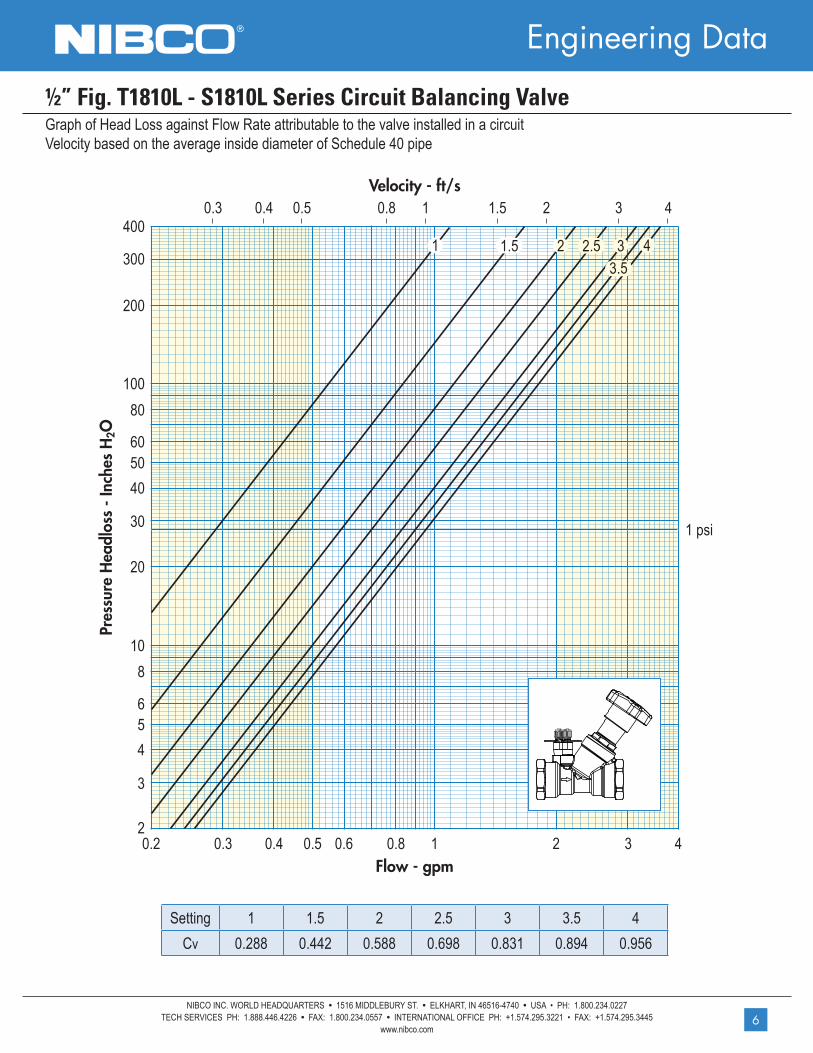
Graph of Head Loss against Flow Rate attributable to the valve installed in a circuit Velocity based on the average inside diameter of Schedule 40 pipe
½” Fig. T1810L - S1810L Series Circuit Balancing Valve
6
Setting 1 1.5 2 2.5 3 3.5 4Cv 0.288 0.442 0.588 0.698 0.831 0.894 0.956
Flow - gpm
Pres
sure
Hea
dlos
s - I
nche
s H
2O
Velocity - ft/s
Engineering Data ®
NIBCO INC. WORLD HEADQUARTERS • 1516 MIDDLEBURY ST. • ELKHART, IN 46516-4740 • USA • PH: 1.800.234.0227TECH SERVICES PH: 1.888.446.4226 • FAX: 1.800.234.0557 • INTERNATIONAL OFFICE PH: +1.574.295.3221 • FAX: +1.574.295.3445
www.nibco.com
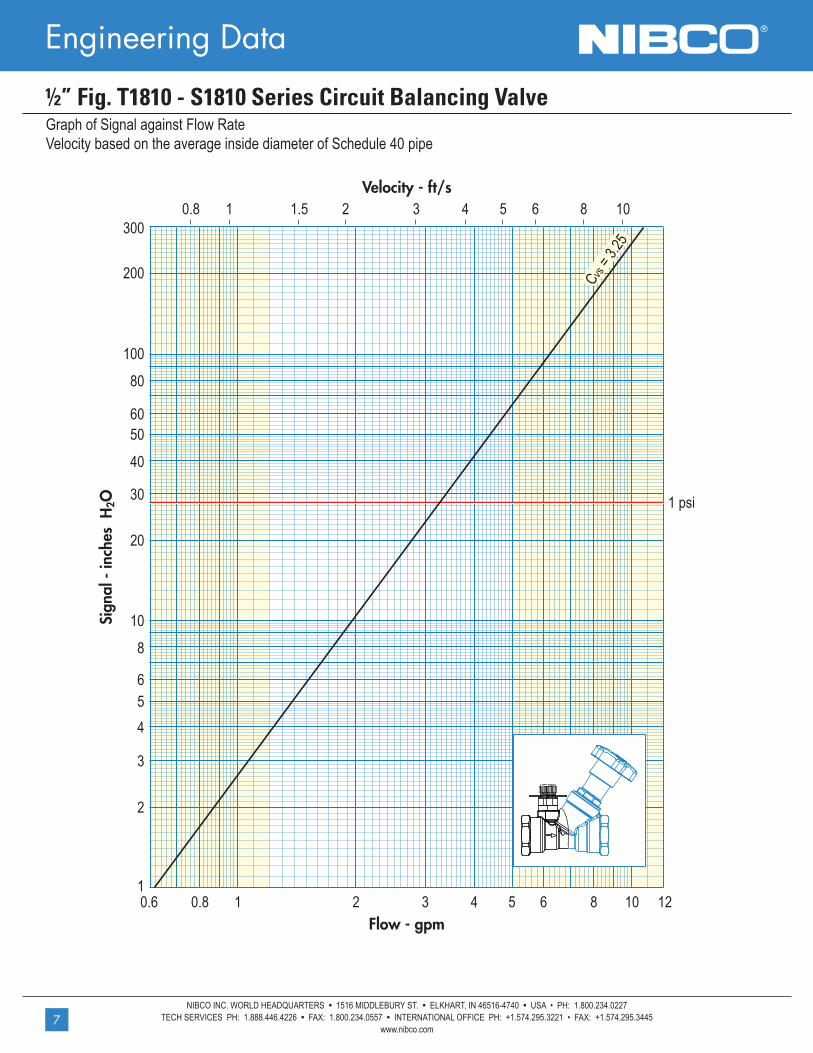
Graph of Signal against Flow Rate Velocity based on the average inside diameter of Schedule 40 pipe
½” Fig. T1810 - S1810 Series Circuit Balancing Valve
7
Flow - gpm
Sign
al -
inch
es H
2O
Velocity - ft/s

Engineering Data®
NIBCO INC. WORLD HEADQUARTERS • 1516 MIDDLEBURY ST. • ELKHART, IN 46516-4740 • USA • PH: 1.800.234.0227TECH SERVICES PH: 1.888.446.4226 • FAX: 1.800.234.0557 • INTERNATIONAL OFFICE PH: +1.574.295.3221 • FAX: +1.574.295.3445
www.nibco.com
Graph of Head Loss against Flow Rate attributable to the valve installed in a circuit Velocity based on the average inside diameter of Schedule 40 pipe
½” Fig. T1810 - S1810 Series Circuit Balancing Valve
8
Setting 1 1.5 2 2.5 3 3.5 4Cv 0.615 0.812 0.998 1.183 1.601 2.042 2.192
Flow - gpm
Pres
sure
Hea
dlos
s - I
nche
s H
2O
Velocity - ft/s

Engineering Data ®
NIBCO INC. WORLD HEADQUARTERS • 1516 MIDDLEBURY ST. • ELKHART, IN 46516-4740 • USA • PH: 1.800.234.0227TECH SERVICES PH: 1.888.446.4226 • FAX: 1.800.234.0557 • INTERNATIONAL OFFICE PH: +1.574.295.3221 • FAX: +1.574.295.3445
www.nibco.com
Graph of Signal against Flow Rate Velocity based on the average inside diameter of Schedule 40 pipe
¾” Fig. T1810 - S1810 Series Circuit Balancing Valve
9
Flow - gpm
Sign
al -
inch
es H
2O
Velocity - ft/s

Engineering Data®
NIBCO INC. WORLD HEADQUARTERS • 1516 MIDDLEBURY ST. • ELKHART, IN 46516-4740 • USA • PH: 1.800.234.0227TECH SERVICES PH: 1.888.446.4226 • FAX: 1.800.234.0557 • INTERNATIONAL OFFICE PH: +1.574.295.3221 • FAX: +1.574.295.3445
www.nibco.com
Graph of Head Loss against Flow Rate attributable to the valve installed in a circuit Velocity based on the average inside diameter of Schedule 40 pipe
¾” Fig. T1810 - S1810 Series Circuit Balancing Valve
10
Setting 1 1.5 2 2.5 3 3.5 4Cv 0.673 1.125 1.392 1.995 2.471 3.399 4.072
Flow - gpm
Pres
sure
Hea
dlos
s - I
nche
s H
2O
Velocity - ft/s

Engineering Data ®
NIBCO INC. WORLD HEADQUARTERS • 1516 MIDDLEBURY ST. • ELKHART, IN 46516-4740 • USA • PH: 1.800.234.0227TECH SERVICES PH: 1.888.446.4226 • FAX: 1.800.234.0557 • INTERNATIONAL OFFICE PH: +1.574.295.3221 • FAX: +1.574.295.3445
www.nibco.com
Graph of Signal against Flow Rate Velocity based on the average inside diameter of Schedule 40 pipe
1” Fig. T1810 - S1810 Series Circuit Balancing Valve
11
Flow - gpm
Sign
al -
inch
es H
2O
Velocity - ft/s

Engineering Data®
NIBCO INC. WORLD HEADQUARTERS • 1516 MIDDLEBURY ST. • ELKHART, IN 46516-4740 • USA • PH: 1.800.234.0227TECH SERVICES PH: 1.888.446.4226 • FAX: 1.800.234.0557 • INTERNATIONAL OFFICE PH: +1.574.295.3221 • FAX: +1.574.295.3445
www.nibco.com
Graph of Head Loss against Flow Rate attributable to the valve installed in a circuit Velocity based on the average inside diameter of Schedule 40 pipe
1” Fig. T1810 - S1810 Series Circuit Balancing Valve
12
Flow - gpm
Pres
sure
Hea
dlos
s - I
nche
s H
2O
Velocity - ft/s
Setting 1 1.5 2 2.5 3 3.5 4Cv 2.424 3.132 4.141 5.301 6.113 6.658 7.122

Engineering Data ®
NIBCO INC. WORLD HEADQUARTERS • 1516 MIDDLEBURY ST. • ELKHART, IN 46516-4740 • USA • PH: 1.800.234.0227TECH SERVICES PH: 1.888.446.4226 • FAX: 1.800.234.0557 • INTERNATIONAL OFFICE PH: +1.574.295.3221 • FAX: +1.574.295.3445
www.nibco.com
Graph of Signal against Flow Rate Velocity based on the average inside diameter of Schedule 40 pipe
1¼” Fig. T1810 - S1810 Series Circuit Balancing Valve
13
Flow - gpm
Sign
al -
inch
es H
2O
Velocity - ft/s

Engineering Data®
NIBCO INC. WORLD HEADQUARTERS • 1516 MIDDLEBURY ST. • ELKHART, IN 46516-4740 • USA • PH: 1.800.234.0227TECH SERVICES PH: 1.888.446.4226 • FAX: 1.800.234.0557 • INTERNATIONAL OFFICE PH: +1.574.295.3221 • FAX: +1.574.295.3445
www.nibco.com
Graph of Head Loss against Flow Rate attributable to the valve installed in a circuit Velocity based on the average inside diameter of Schedule 40 pipe
1¼” Fig. T1810 - S1810 Series Circuit Balancing Valve
14
Flow - gpm
Pres
sure
Hea
dlos
s - I
nche
s H
2O
Velocity - ft/s
Setting 1 1.5 2 2.5 3 3.5 4Cv 3.967 4.849 6.287 9.187 12.250 13.990 14.546

Engineering Data ®
NIBCO INC. WORLD HEADQUARTERS • 1516 MIDDLEBURY ST. • ELKHART, IN 46516-4740 • USA • PH: 1.800.234.0227TECH SERVICES PH: 1.888.446.4226 • FAX: 1.800.234.0557 • INTERNATIONAL OFFICE PH: +1.574.295.3221 • FAX: +1.574.295.3445
www.nibco.com
Graph of Signal against Flow Rate Velocity based on the average inside diameter of Schedule 40 pipe
1½” Fig. T1810 - S1810 Series Circuit Balancing Valve
15
Flow - gpm
Sign
al -
inch
es H
2O
Velocity - ft/s
Engineering Data®
NIBCO INC. WORLD HEADQUARTERS • 1516 MIDDLEBURY ST. • ELKHART, IN 46516-4740 • USA • PH: 1.800.234.0227TECH SERVICES PH: 1.888.446.4226 • FAX: 1.800.234.0557 • INTERNATIONAL OFFICE PH: +1.574.295.3221 • FAX: +1.574.295.3445
www.nibco.com
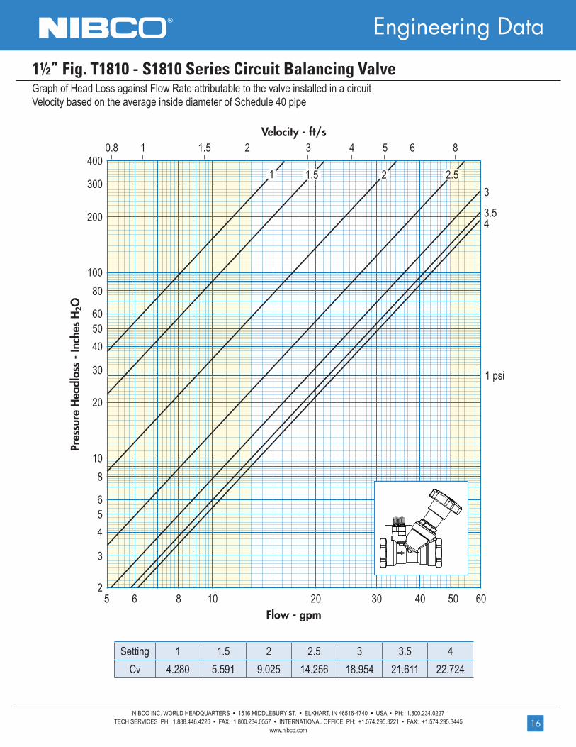
Graph of Head Loss against Flow Rate attributable to the valve installed in a circuit Velocity based on the average inside diameter of Schedule 40 pipe
1½” Fig. T1810 - S1810 Series Circuit Balancing Valve
16
Flow - gpm
Pres
sure
Hea
dlos
s - I
nche
s H
2O
Velocity - ft/s
Setting 1 1.5 2 2.5 3 3.5 4Cv 4.280 5.591 9.025 14.256 18.954 21.611 22.724

Engineering Data ®
NIBCO INC. WORLD HEADQUARTERS • 1516 MIDDLEBURY ST. • ELKHART, IN 46516-4740 • USA • PH: 1.800.234.0227TECH SERVICES PH: 1.888.446.4226 • FAX: 1.800.234.0557 • INTERNATIONAL OFFICE PH: +1.574.295.3221 • FAX: +1.574.295.3445
www.nibco.com
Graph of Signal against Flow Rate Velocity based on the average inside diameter of Schedule 40 pipe
2” Fig. T1810 - S1810 Series Circuit Balancing Valve
17
Flow - gpm
Sign
al -
inch
es H
2O
Velocity - ft/s
Engineering Data®
NIBCO INC. WORLD HEADQUARTERS • 1516 MIDDLEBURY ST. • ELKHART, IN 46516-4740 • USA • PH: 1.800.234.0227TECH SERVICES PH: 1.888.446.4226 • FAX: 1.800.234.0557 • INTERNATIONAL OFFICE PH: +1.574.295.3221 • FAX: +1.574.295.3445
www.nibco.com
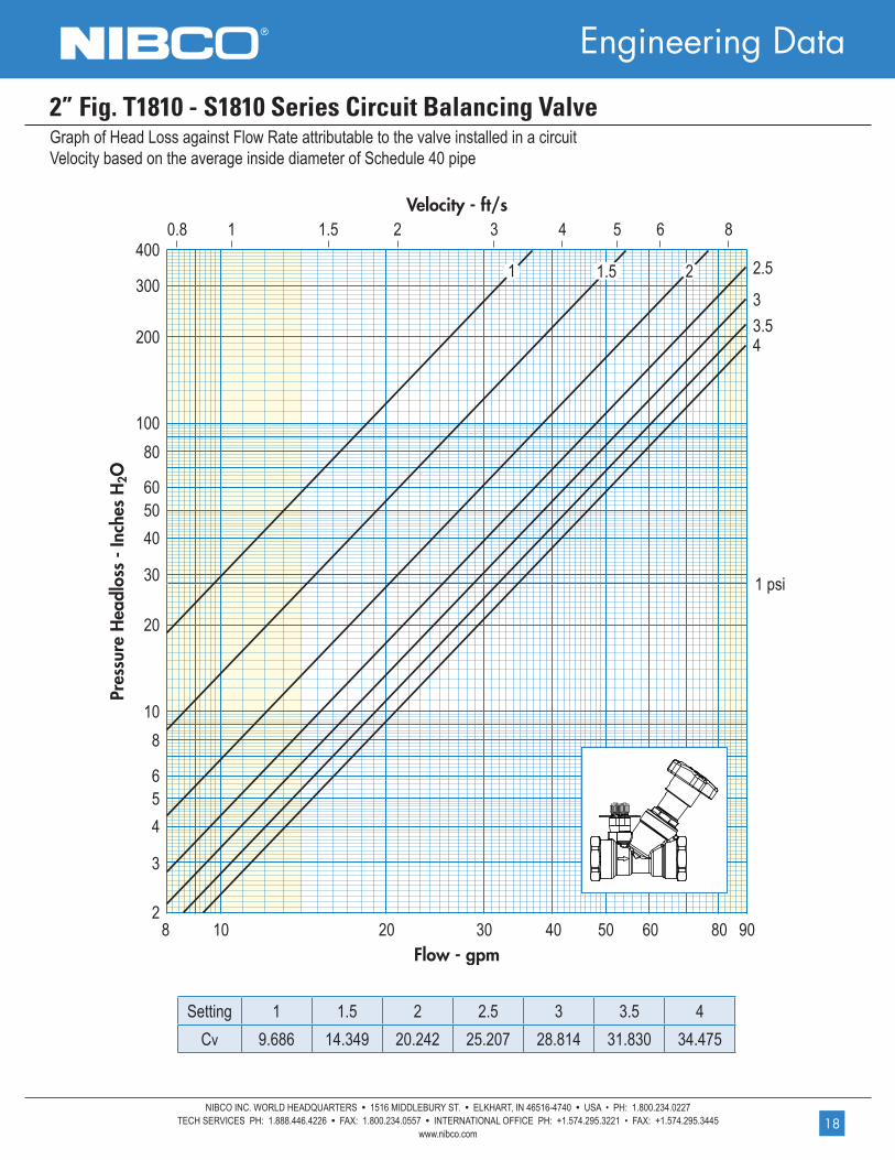
Graph of Head Loss against Flow Rate attributable to the valve installed in a circuit Velocity based on the average inside diameter of Schedule 40 pipe
2” Fig. T1810 - S1810 Series Circuit Balancing Valve
18
Flow - gpm
Pres
sure
Hea
dlos
s - I
nche
s H
2O
Velocity - ft/s
Setting 1 1.5 2 2.5 3 3.5 4Cv 9.686 14.349 20.242 25.207 28.814 31.830 34.475
NIBCO INC.
WORLD HEADQUARTERS
WEB: www.nibco.com
1516 MIDDLEBURY STREET
ELKHART, IN 46516-4740
USA
DOMESTIC CUSTOMER SERVICE
PHONE: 800.234.0227
FAX: 800.234.0557
TECHNICAL SERVICE
PHONE: 888.446.4226
FAX: 888.336.4226
INTERNATIONAL OFFICE
PHONE: +/574.295.3221
FAX: +/574.295.3455
AHEAD OF THE FLOW®
08/15
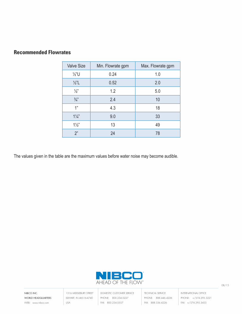
Valve Size Min. Flowrate gpm Max. Flowrate gpm
½”U 0.24 1.0
½”L 0.52 2.0
½” 1.2 5.0
¾” 2.4 10
1” 4.3 18
1¼” 9.0 33
1½” 13 49
2” 24 78
Recommended Flowrates
The values given in the table are the maximum values before water noise may become audible.