fire behaviour of steel columns
TRANSCRIPT
Aleksandra Cvetanovska
FIRE BEHAVIOUROF STEEL COLUMNS
UNIVERSITY “Ss Cyril and Methodius”FACULTY OF CIVIL ENGINEERING – SKOPJE

FIRE IN BUILDINGS
CONSEQUENCES:
- Material damages
- Human injuries and lost of lives
STATISTICAL INFORMATION:Cumulative fire damages are beiger then damages made by earthquakes
FIRE SAFETY OBJECTIVES
1. Protection of human lives
2. Protection of neighboring buildings
3. Protection of material goods in the building
4. Avoiding non tolerant ecologic damaged

FIRE IN BUILDINGS
CONSEQUENCES:
- Material damages
- Human injuries and lost of lives
STATISTICAL INFORMATION:Cumulative fire damages are beiger then damages made by earthquakes
STRUCTURAL FIRE SAFETY REQUIREMENTS
1. To provide bearing capacity in fire condition for required time
2. To prevent fire spread on neighboring buildings
3. To provide condition for people evacuation
4. To provide condition for fire extinguishing

FIRE INFLUENCE ON STEEL STRUCTURES
MATERIAL DEGRADATION
- Decrease of yield stress
- Decrease of strength limit
- Decrease of modulus of elasticity- Significant changes in s-e relation
This material degradation cause significant increase of structural deformations which lead to:
Stability problems / Lost of load bearing capacity
RAPID HEATINGHIGH TEMPERATURES
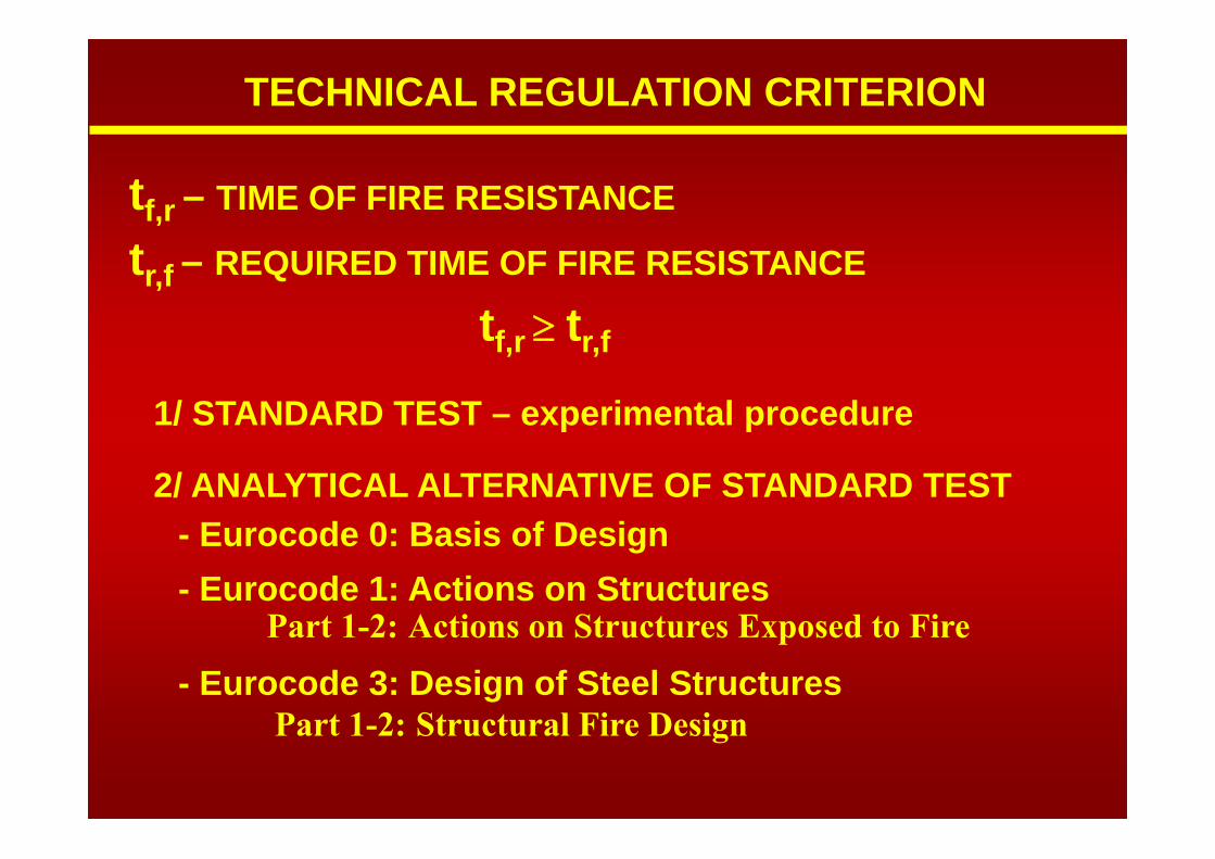
TECHNICAL REGULATION CRITERION
tf,r – TIME OF FIRE RESISTANCE
tr,f – REQUIRED TIME OF FIRE RESISTANCE
tf,r tr,f
1/ STANDARD TEST – experimental procedure
2/ ANALYTICAL ALTERNATIVE OF STANDARD TEST- Eurocode 0: Basis of Design- Eurocode 1: Actions on Structures
Part 1-2: Actions on Structures Exposed to Fire
- Eurocode 3: Design of Steel StructuresPart 1-2: Structural Fire Design

THERMAL ACTION
EC1: Part 1.2: Actions on Structures Exposed to Fire

0 60
200
400
600
800
1000
1200
120 180
q 2=750MJ/mt,d
100
O=0.06m1/2
b 22 1/=1500J/m s K
t [min]
[ C]o
250
500
ISO 834
0 60
200
400
600
800
1000
1200
120 180
q 2=750MJ/mt,d
100
O=0.06m1/2
b 22 1/=1500J/m s K
t [min]
[ C]o
250
500
ISO 834
FIRE LOAD DENSITY
t
iii,ui,k
t
k,fik,t,fi A
mHMA
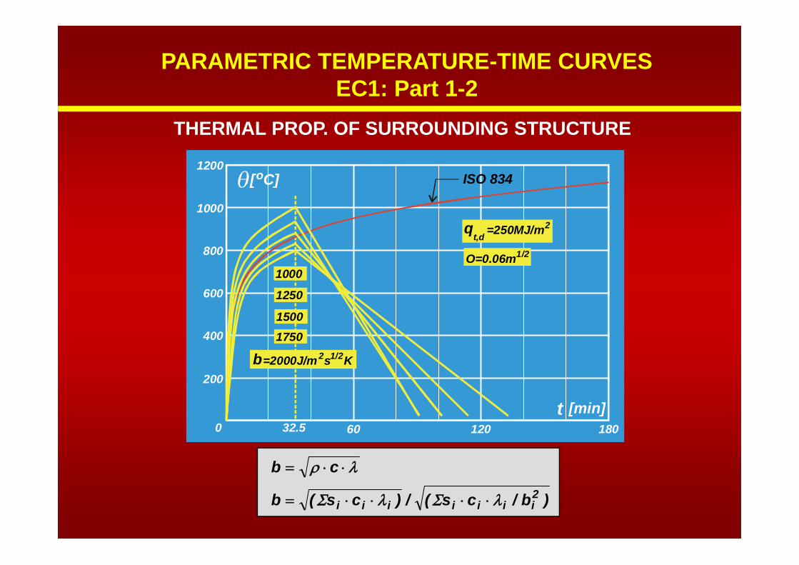
PARAMETRIC TEMPERATURE-TIME CURVESEC1: Part 1-2

0 60
200
400
600
800
1000
1200
120 180
q 2=250MJ/mt,d
O=0.04m1/20.060.08
0.12
b 22 1/=1500J/m s K
t [min]
[ C]o
ISO 834
0 60
200
400
600
800
1000
1200
120 180
q 2=250MJ/mt,d
O=0.04m1/20.060.08
0.12
b 22 1/=1500J/m s K
t [min]
[ C]o
ISO 834
tvv A/hAO
OPENING FACTOR
PARAMETRIC TEMPERATURE-TIME CURVESEC1: Part 1-2
PARAMETRIC TEMPERATURE-TIME CURVESEC1: Part 1-2
0 60
200
400
600
800
1000
1200
120 180
O=0.06m1/2
b 22 1/=2000J/m s K
1250
15001750
1000
q 2=250MJ/mt,d
ISO 834
32.5t [min]
[ C]o
0 60
200
400
600
800
1000
1200
120 180
O=0.06m1/2
b 22 1/=2000J/m s K
1250
15001750
1000
q 2=250MJ/mt,d
ISO 834
32.5t [min]
[ C]o
cb
)b/cs(/)cs(b 2iiiiiii
THERMAL PROP. OF SURROUNDING STRUCTURE
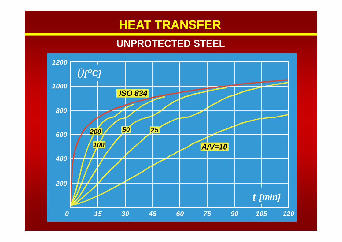
HEAT TRANSFERUNPROTECTED STEEL
HEAT TRANSFER
15 30 45 60 75 90 105 1200
200
400
600
800
1000
1200
50 25
100
200
t [min]
[ C]o
A/V=10
ISO 834
15 30 45 60 75 90 105 1200
200
400
600
800
1000
1200
50 25
100
200
t [min]
[ C]o
A/V=10
ISO 834
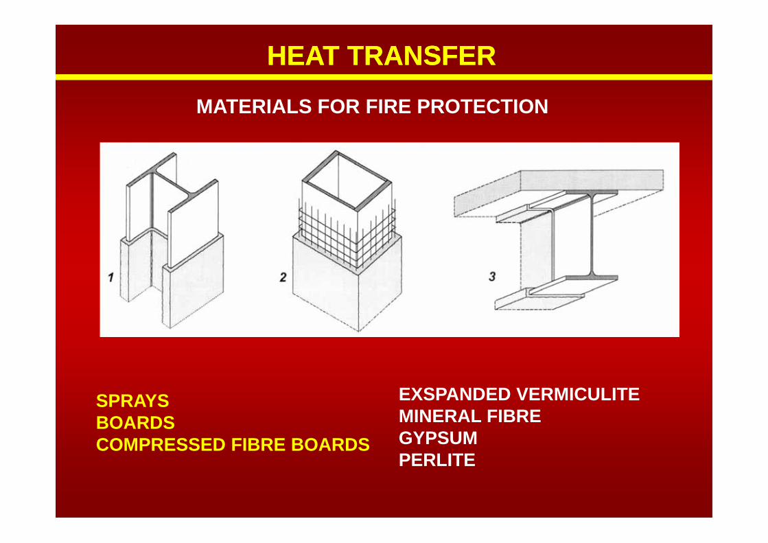
MATERIALS FOR FIRE PROTECTION
SPRAYSBOARDSCOMPRESSED FIBRE BOARDS
EXSPANDED VERMICULITEMINERAL FIBREGYPSUMPERLITE
HEAT TRANSFERHEAT TRANSFER

HEAT TRANSFERPROTECTED STEEL
HEAT TRANSFER
15 30 45 60 75 90 105 1200
200
400
600
800
1000
1200
100
200
200300
300
c
d
p
p
p
p
= 0.15 W/mK
= 600 kg/m3
= 1200 J/kgK
= 0.02 m
t [min]
[ C]o
A/V=100
ISO 834
15 30 45 60 75 90 105 1200
200
400
600
800
1000
1200
100
200
200300
300
c
d
p
p
p
p
= 0.15 W/mK
= 600 kg/m3
= 1200 J/kgK
= 0.02 m
t [min]
[ C]o
A/V=100
ISO 834
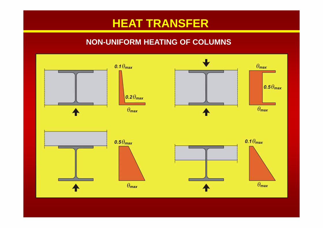
NON-UNIFORM HEATING OF COLUMNS
HEAT TRANSFER

MECHANICAL PROPERTIES: EC3, Part 1.2
REDUCTION FACTORS
0
0.2
0.4
0.6
0.8
1.0
100 300200 500400 600 700 800 900
[ C]o
k
k f f/=y, y, y
Effective yield stress
Slope of linearelastic range
k E E/=E, a, a Proportional
limitk f f/=p, p, p

MECHANICAL PROPERTIES: EC3, Part 1.2
Shape of diagram at elevated temperatures

FIRE BEHAVIOUR OF STEEL COLUMNS
BUCKLING RESISTANCE OF COMPRESSED ELEMENT(EC3: Part 1-2)
The design buckling resistance Nb,fi,t,Rd at time t of a compressionmember with a Class 1, Class 2 or Class 3 cross-section with a uniformtemperature θ a should be determined from::

FIRE BEHAVIOUR OF STEEL COLUMNS
1/ MULTI STORY BRACED FRAMES2/ HORIZONTAL FIRE COMPARTMENTISATION
RIG
ID C
OR
E
defo
rmat
ion
in fi
re
bucklinglength
L
L
=0.7 L
L L
L L
=0.5 L
.
.
fi
fi
43
21
2
HORIZONTALFIRE COMPARTMENT
COMPRESSED ELEMENTS – BUCKLING LENGTH

FIRE BEHAVIOUR OF STEEL COLUMNS
NON-UNIFORM HEATING IN THE CROSS-SECTION
HEB300, S235, STRONG AXES
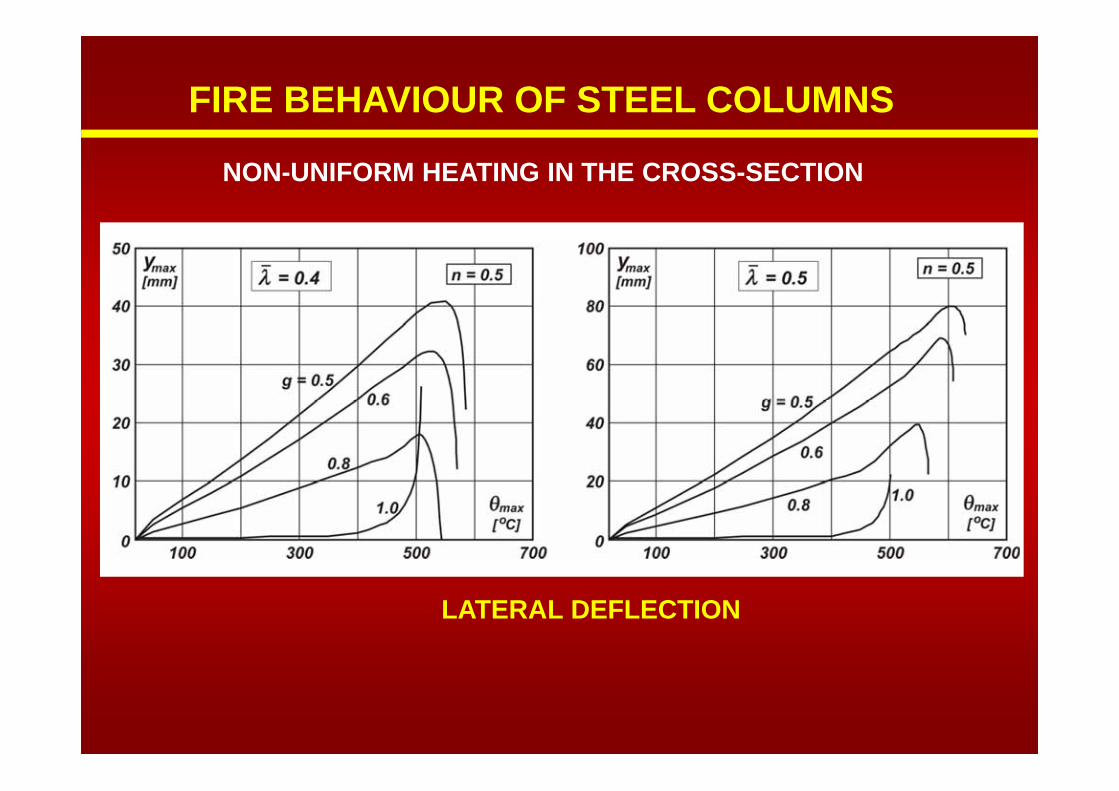
FIRE BEHAVIOUR OF STEEL COLUMNS
NON-UNIFORM HEATING IN THE CROSS-SECTION
LATERAL DEFLECTION

FIRE BEHAVIOUR OF STEEL COLUMNS
INFLUENCE OF ROTATIONAL RESTRAINTS
HEB300, S235, STRONG AXES

FIRE BEHAVIOUR OF STEEL COLUMNS
INFLUENCE OF AXIAL RESTRAINTS
HEB300, S235, STRONG AXES

FIRE BEHAVIOUR OF STEEL COLUMNS
INFLUENCE OF AXIAL RESTRAINTS
Eccentrically compressed column (HEB220)

CONCLUSIONSSTRUCTURAL FIRE BEHAVIOR AND FIRE RESISTANCE
IS A PART OF STRUCTURAL DESIGNAssessment of the fire compartment parameters is a necessary condition to define adequate measures and concept of fire safety. The temperature distribution and the rate of heating depend on structural parameters. These parameters should be defined in the structural design and they are base for calculation of necessity, type and amount of thermal protection.
Rotational restraints at columns have beneficial effect expressedby decrease of buckling length for room temperatures, especiallyfor columns exposed to fire, where the increase of critical temperature is in range of 100-200oC.
Axial restraint of fire exposed columns has detrimental effect on the stability and the critical member temperature. This effect can be neglected only for columns with low slenderness ratios. Increase of the slenderness ratio leads to decrease in the column critical temperature (50-300oC).

THANKS FOR YOUR ATTENTION