finsley gate report 355 (2) - burnley borough council gate mill...finsley gate mill burnley...
TRANSCRIPT

FINSLEY GATE MILL
BURNLEY
LANCASHIRE
SD 84190 32050
HISTORIC BUILDING RECORDING
OCTOBER 2011
C A S T L E R I N G A R C H A E O L O G Y
R E P O R T N O . 3 5 5

CASTLERING ARCHAEOLOGY REPORT 355, 2
CASTLERING ARCHAEOLO GY REPORT NO. 355
FINSLEY GATE MILL
BURNLEY
LANCASHIRE
SD 84190 32050
HISTORIC BUILDING RE CORDING
CONTRACTED BY:
ST MODWEN DEVELOPMENTS LTD CHEPSTOW HOUSE
TRIDENT BUSINESS PARK DATEN AVENUE
RISLEY WARRINGTON
WA3 6BX
UNDERTAKEN BY
PAT FROST BA, MIFA, CONSULTANT ARCHAEOLOGIST
CASTLERING ARCHAEOLOGY
33, STALLION LANE, PONTESBURY, SHROPSHIRE. SY5 0PN
TEL: 01743 792297 MOBILE: 07971751978
email: [email protected]
www.castleringarchaeology.co.uk

CASTLERING ARCHAEOLOGY REPORT 355, 3
SYNOPSIS
This report contains the result of a programme of building recording undertaken at Finsley Gate Mill, Burnley, prior to any redevelopment. The mill site comprises a series of 19th century buildings on the north bank of the Leeds & Liverpool Canal. The mill lies within the Canalside Conservation Area but has not fulfilled the current criteria for Listed building status by English Heritage. The mill is one of the many former steam-powered buildings purpose-built on the principle of rectangular design, with floors supported by cast iron columns, to house the growing 19th century cotton industry in Burnley. Nevertheless the mill is considered to be of sufficient historical, architectural and industrial archaeological interest to warrant a programme of building recording prior to any further developments on the site. Fishwick provides the first cartographic record of a mill on the site, which has taken its name from the nearby Turn Bridge. The mill was built in the 1820s and subsequently renamed Finsley Gate Mill. Little evidence remains of the first mill on the site as occupied by Holgates, other than the sandstone walls that form the west side of the existing 4-storey mill. Holgates are recorded in Trade Directories from 1828 until 1843 and from 1846 Henry Knowles & Sons appear to have taken over the premises. Cartographic evidence suggests that the existing 3-storey stone-built warehouse was added to the west side of the site c.1848 / 1849 by Henry Knowles. At this time the engine house and chimney were sited between the old mill and the canal. In September 1852 the Burnley Advertiser reported on the horrific boiler explosion at the mill when eleven were injured, four of whom died within 24 hours. It seems likely that the sandstone Power House that stands on site today was built shortly after this 1852 explosion, the size and location of the building being dictated by the warehouse built shortly before. In 1866, the Burnley Gazette reported on a fire that almost gutted the mill, reportedly causing £20,000 worth of damage and one fatality, an eleven year old boy. Following the fire, most of the 1820s Turn Bridge Mill appears to have been cleared and a new mill built by the Knowles family. The 1866 building is represented in the lower three storeys of the prominent mill building that stands on the site today. The northeast elevation fronting Finsley Gate bears the 1866 datestone and Knowles containing 30,000 spindles with machinery that . The fourth and upper storey is clearly added at a later date. Towards the end of the 19th century, Witham Bros. took over the mill. The 1893 OS map shows that by this time the canalside chimney had been demolished and the existing brick chimney built together with the boiler house. The existing steel framed bridge over the canal had been constructed connecting Finsley Gate Mill to a Coal Depot, which provided a source of fuel for the three Lancashire boilers that survive on the site today. In 1945 Joshua Hoyle & Sons took over the Mill from Witham Bros. and continued to work there until 1959. Under their ownership, the modern lift shaft on the northwest corner of the 1866 building was added c.1950. In 1959, Lambert Howarth, who had taken over Healey Royd Mill in 1939, acquired Finsley Gate Mill, thus operating premises on both banks of the canal. The company went into administration in January 2007 and Healey Royd and Finsley Gate were bought by St Modwen Developments Ltd. The present site principally comprises three buildings of sandstone construction: the mill built in 1866; the mid-19th century Power House and Warehouse together with the red-brick late 19th century Chimney and Boiler House and the early 20th century single storey shed. The 1866 Mill and c.1848 Warehouse are constructed around the principle of rectangular design with floors supported by cast iron columns. All machinery associated with the spinning mill was presumably removed in 1959 and the rare survival of three Lancashire boilers on the site is attributed to their continued use for heating. The Mill has stood empty since 2007. Sadly, in the intervening years, the building has been subjected to several forays of vandalism and robbery, notwithstanding the security arrangements made by St. Modwens. In consequence, several major decisions have to be made in respect of both sites. The current programme of work and the plans undertaken by Tower Surveys in 2004 have ensured that a record has been made of the existing site prior to any demolition and subsequent redevelopment.

CASTLERING ARCHAEOLOGY REPORT 355, 4
LIST OF CONTENTS
1. Introduction 2. Aim of the Project 3. Methodology Fig. 1 Site Location Plate 1 Site Location, view from the south 2006 Plate 2 Site Location, view from the south 2011 4. History of the Mill Site Cartographic evidence Figs 3-7 Plate 3 5. The Existing Site Plates 4-22 6. Photographic Illustration Plates 23- 90 7. Site Survey Drawings 8. Discussion 9. Acknowledgements 10. Sources Appendix 1 Copy of the Project Briefs Appendix 2 Copy of the Project Design Appendix 3 Digital Photographic Archive Abbreviations BL Burnley Library c. circa DoE Department of the Environment LCC Lancashire County Council LRO Lancashire Record Office LSMR Lancashire Sites and Monuments Record OS Ordnance Survey PRN Primary Record Number

CASTLERING ARCHAEOLOGY REPORT 355, 5
1 . INTRODUCTION
1.1 This report forms Stage 2 of a programme of archaeological recording undertaken on two mill sites located south of the town centre of Burnley. Healey Royd Mill and Finsley Gate Mill were bought by St Modwen Developments Ltd in 2007 with a view to developing a high quality mixed use scheme that would enable re-use of the two mill sites (Application No. 12/07/0042). The subject of this report is Finsley Gate Mill, sited between the road also known as Finsley Gate and the north bank of the Leeds and Liverpool Canal that separates the two former mill sites (Fig. 1 & Plates 1 & 2 following). Stage 1 works were completed on Healey Royd Mill in January 2009 and the results published as Castlering Archaeology Report No. 300. 1.2 Finsley Gate Mill lies within Burnley Canalside Conservation Area, which extends along much of the length of the Leeds and Liverpool Canal within the town. Finsley Gate Mill, Healey Royd Mill, and the adjacent Finsley Wharf, the former canal boat yard, . is a concentration of mills and terraced housing that developed from the end of the eighteenth century following the construction of the Leeds and Liverpool Canal. Both Healey Royd and Finsley Gate Mills lie outside the core of the Weavers Triangle and neither has been afforded statutory protection by English Heritage. Planning Background 1.3 Consultation with Doug Moir, Planning Officer (Archaeology), Lancashire County Archaeology Service, acting as advisor to Burnley Borough Council, resulted in proposals for a programme of historic building recording to be undertaken prior to future phases of development on both mill sites (Appendix 1A; May 2007). In June 2007, Castlering Archaeology was contracted by St Modwen Developments Ltd. to undertake the prescribed archaeological work following the guidance of the Planning Officer (Archaeology). A Written Scheme of Investigation (Appendix 2 WSI) for the prescribed works was submitted to and subsequently approved by the Planning Officer (Archaeology). 1.4 The recommendation followed the advice given by central government as set out in Planning Policy Guidance: Planning and the Historic Environment (PPG 15) and Planning Policy Guidance: Archaeology and Planning (PPG 16) issued by the DoE. Both PPG 15 and PPG 16 have since been replaced by the Department for Communities and Local Government Planning Policy Statement 5: Planning for the Historic Environment (March 2010). 2011 Revised Proposals 1.5 Since 2007 both mills have suffered from vandalism and professional looting, rendering them too damaged for restoration. In consequence, several major decisions have had to be made in respect of both sites.
1.6 In March 2011 outline planning permission and conservation area consent were granted by Burnley Borough Council in respect of revised proposals for the two mill sites. The revised proposals comprise the
demolition of Healey Royd Mill
and at Finsley Gate Mill demolition of modern brick additions
demolition of the late 19th century Chimney
demolition of the late 19th early 20th century single storey shed alongside Finsley Gate

CASTLERING ARCHAEOLOGY REPORT 355, 6
stripping out the internal fabric of the mill, including all floors and supporting cast iron columns
insertion of modern structural support
retention of the façade of Finsley Gate Mill in the short to medium term
with the ultimate aim of regenerating the present site.
1.7 In September 2011, a revised Specification for archaeological recording of Finsley Gate Mill was prepared by Doug Moir, Planning Officer (Archaeology) for Drivers Jonas Deloitte, acting on behalf of St Modwen Developments (Appendix 1B). In April and October 2011 Castlering Archaeology was granted limited access to the interior of the mill in order to complete the programme of building recording as recommended in 2007. 1.8 This report is submitted as a condition of Conservation Area Consent APP/2010/0608 which proposes the partial demolition of Finsley Gate Mill complex with the exception of the elevations of the stone-built structures on site, which comprise the 1866 mill, the 1848 Warehouse and the former Power House that links these two buildings.
2 . AI M OF THE PROJECT
The aim of the programme of historic building recording is to:
provide a record of the site prior to any development
identify and objectively record by means of photographs and annotated drawings any significant evidence for the
original and subsequent historical form and functions of the building
analyse and interpret the building as part of an integrated system intended to perform a specialised function
determine the functional arrangements and division of the building and the roles of the historical plan form, technical layout and process flow, as far as these aims are possible.

CASTLERING ARCHAEOLOGY REPORT 355, 7
3 . METHODOLOGY
3.1 The following programme of historic building recording has been undertaken: Desk-based assessment to assist in the interpretation of the site 3.2 The desk-based study has consulted primary and secondary sources held at the following repositories:
Lancashire Sites and Monuments Record Lancashire County Record Office, Preston
Burnley Local Studies Library
On-site Building Recording 3.3 The recording is based on a Level 2/3 survey, as specified in Understanding Historic Buildings: A guide to good
recording practice (English Heritage 2006). The recording comprises:
general external photographic record of the site undertaken in June 2007 external and internal photographic record undertaken in April 2011 and supplemented in October 2011
Interpretation of architect s drawings
Photographic Record 3.4 The photographic record has been undertaken in 35mm monochrome, digital format and a selection of colour slides. A selection of the digital photography is included in this report and the full photographic record will be deposited at Lancashire County Record Office, Preston as part of the site archive. The full digital photo archive is included as Appendix 3 of this report. Survey Drawings 3.5 The survey was undertaken by Tower Surveys of Nottingham in April 2004. Copies of the drawings are included in Section 7 as hard copies within the A4 report and on CD-ROM in digital copies of the report. The record includes measured floor plans, elevations and cross-sections of the main buildings.

CASTLERING ARCHAEOLOGY REPORT 355, 8
Fins
ley
Gat
e M
ill

CASTLERING ARCHAEOLOGY REPORT 355, 9
Plate 1: Finsley Gate & former Healey Royd Mills, view from the south
prior to any works on site (www.maplandia.com, c.2006)
Plate 2: Finsley Gate & Healey Royd Mills, following demolition on the Healey Royd site, 2011 (google-earth)
Finsley Gate Mill
Healey Royd Mill complex
Healey Royd Mill
Finsley Gate Mill

CASTLERING ARCHAEOLOGY REPORT 355, 10
4 . HISTORY OF THE MILL SITE
4.1 Although textiles had been made in the Burnley area since medieval times at least, it was the on-set of the period
town. 4.2 During the second half of the 18th century, the manufacture of cotton began to replace that of wool, and changes in technology brought about the decline of the domestic industry. Textile manufacture which had been mainly carried out in the workers own homes moved to a factory-based industry. The first mills in the town were built near the rivers until, in the 18th century, the adaptation of the steam engine for mill use freed the mills from their reliance on water-power. The steam engine was applied to factories in Burnley by the end of the 18th century and by 1801 the Leeds and Liverpool Canal had reached the south side of the town by means of the embankment built over the Rivers Calder and Brun. During the 19th century, the population of Burnley soared as people moved into the town to take up employment in the increasing number of mills and other associated industries. By 1886 Burnley was producing more cotton cloth per year than any other town in the world and making more looms than any other place in the country. 4.3 The construction of the canal and the proximity of the coalfields greatly contributed to industrial development on the south side of the town, allowing raw materials and coal for fuelling the steam engines that powered the machinery to be easily transported. The canal also provided a water supply for the mill boilers and was readily available for fire fighting. Across the canal from the Finsley Gate Mill, the Wharf was constructed as a boat and maintenance yard for the Canal Company. Cotton Mills were established along the line of the canal and away from the congestion of the town centre; larger mills could be built to accommodate a mixed production of spinning and weaving with the addition of single-storey sheds with large working floor areas. 1820s-1850 4.4 Henry Fishwick, a local surveyor and land agent, produced the first detailed town plan of Burnley in 1827 (Fig. 2 overleaf). The map records the straight line of the canal embankment as it extends south to the wooden Turn Bridge and the Canal Boat Yard, before turning sharp west. On the north bank of the canal, a mill has already been established on the Finsley Gate site, taking its name from the nearby Turn Bridge. 4.5 There can be some , when studying lists of cotton manufacturers and trade directories. However, Bennett (1949, 3, 181) states that Turn Bridge Mill was built by the Holgates around 1820. He states that the site was taken over by the Knowles family of
Barnoldswick and later by the Whithams. Jack Nadin, a local historian, confirms this history in his recent book published in 2008. John and George Holgate are recorded as Turn Bridge Mill Directory of 1828 and the Holgates continue to be mentioned in Trade Directories until 1843. From 1846 Henry Knowles & Sons appear to have taken over the premises. 4.6 for the first mill on the site, while Merryweather in 1841 (Fig. 3 overleaf) and the OS maps published in 1848 and 1851 show a more regular rectangular building flanking the canal. Merryweather 1841 map shows the location of the first Chimney on site, which stood mid-way along the long axis of the mill on the canal side. The position of the chimney suggests the first engine house was sited within the rectangular building. 4.7 The large-scale OS town map, surveyed in 1849 and published in 1851 (Fig. 4 overleaf), provides the first cartographic record of the existing sub-square warehouse that stands towards the northwest side of the site. The warehouse was unrecorded by the OS in 1848 and therefore built in the short period before the 1849 survey was undertaken. The map also provides the first record of the three cotton mills working in close proximity; Healey Royd Mill built on the south bank of the canal and Turn Bridge Mill and Finsley Mill on the north bank.

CASTLERING ARCHAEOLOGY REPORT 355, 11
Fig. 2 1827 Plan of Burnley by Fishwick
Fig. 3 1841 Plan of Burnley by Merryweather
Fig. 4 OS large-scale map surveyed in 1849 and published in 1851
Finsley Gate Mill
Finsley Gate Mill
Finsley Gate Mill
CASTLERING ARCHAEOLOGY REPORT 355, 12
4.8 While under the ownership of Henry Knowles & Sons, a horrific boiler explosion occurred at the mill on September 1st 1852. The explosion was reported in the Burnley Advertiser which described A huge valley of steam, fire and boiling water and hot ashes engulfed several people ; eleven were injured, four of whom died within 24 hours. Many boiler explosions occurred when water levels dropped below the top of the internal boiler flue causing the intense heat of the furnace to burn through the metal casing. Low water safety valves as used on the Lancashire boilers were subsequently developed to avert such accidents. It seems likely that the sandstone Power House that stands on site today was built shortly after this 1852 explosion, the size and location of the building being dictated by the warehouse built shortly before. 4.9 The risk of a fire was prevalent in the cotton mills and, in 1866, the Burnley Gazette reported on a fire that almost gutted the mill, reportedly causing £20,000 worth of damage and one fatality, an eleven year old boy. Nadin (2008) adds that the fire was extinguished by breaking steam pipes. 1866 Rebuilding 4.10 Following the fire, most of the 1820s Turn Bridge Mill site appears to have been cleared and a new mill built by the Knowles family. This is the lower three storeys of the prominent mill building that stands on the site today. The northeast elevation fronting Finsley Gate bears the 1866 datestone (Plate 3 overleaf). The 1866 Mill occupied by Henry Knowles & Sons, Cotton Spinners & Manufacturers, contained 30,000 spindles and the machinery
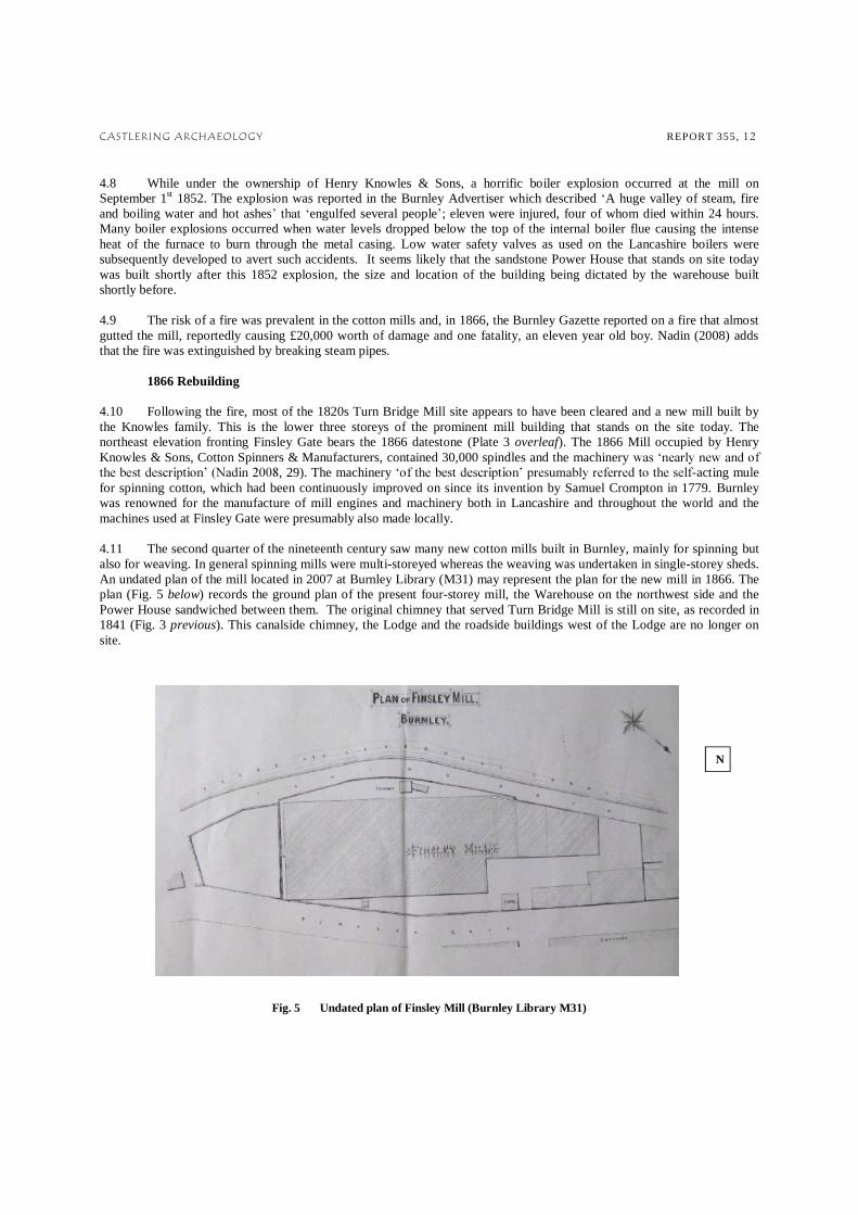
, 29). The machinery -acting mule for spinning cotton, which had been continuously improved on since its invention by Samuel Crompton in 1779. Burnley was renowned for the manufacture of mill engines and machinery both in Lancashire and throughout the world and the machines used at Finsley Gate were presumably also made locally. 4.11 The second quarter of the nineteenth century saw many new cotton mills built in Burnley, mainly for spinning but also for weaving. In general spinning mills were multi-storeyed whereas the weaving was undertaken in single-storey sheds. An undated plan of the mill located in 2007 at Burnley Library (M31) may represent the plan for the new mill in 1866. The plan (Fig. 5 below) records the ground plan of the present four-storey mill, the Warehouse on the northwest side and the Power House sandwiched between them. The original chimney that served Turn Bridge Mill is still on site, as recorded in 1841 (Fig. 3 previous). This canalside chimney, the Lodge and the roadside buildings west of the Lodge are no longer on site.
Fig. 5 Undated plan of Finsley Mill (Burnley Library M31)
N

CASTLERING ARCHAEOLOGY REPORT 355, 13
Plate 3: 1866 datestone
Late 19th century additions 4.12 The application to Burnley Borough Council in 1875 to raise the 1866 Mill by one storey was clearly approved and implemented, as shown by the continuous stone string band between the two upper storeys of the present building (Plate 23 following). The narrow lift shaft recorded on the c.1866 plan (Fig. 5 previous) was also raised to reach the top floor (Plate 34 following). 4.13 Towards the end of the 19th century, Witham Bros. Ltd., Cotton Spinners, took over the mill. Withams, a prominent local family, worked Finsley Gate Mill for spinning and Plumbe Street Shed for weaving as one concern at this time, undertaking all the processes involved in the manufacture of cotton goods. 4.14 By 1893, both mill buildings on the north side of the canal are named as Finsley Mill. The 1893 OS map (Fig. 6 below) records the expansion of Healey Royd Mill and the Coal Depot on the south bank of the canal. In 1878 Messrs Brooks and Pickles had applied to the 2007, 16). The Depot fronted the canal and a tramway ran to it from Towneley Colliery, from where coal was transported to be distributed by boat. By 1893, the existing steel framed bridge over the canal (Plates 39-43 following) had been constructed connecting Finsley Gate Mill to the Coal Depot, which provided a source of fuel for the boilers. 4.15 By 1893, the canalside chimney had been demolished and the new brick chimney built west of the mill complex (Plate 24 following). The chimney stands on site today, perhaps built to serve a new and more powerful engine and / or required as local legislation at this time called for all mill chimneys in the town to be at least 90ft high (Bennett 1951, 4, 106). Also by 1893, the red-brick Boiler House adjoining the warehouse has been built and the new brick front that covers part of the northwest elevation of the Power House has been added (Plates 27 & 28 following).
Fig. 6 1893 OS map
Existing Finsley Gate Mill

CASTLERING ARCHAEOLOGY REPORT 355, 14
The early 20th century site 4.16 By the first decade of the 20th century, Burnley had become one of the most important cotton producing towns in the world and nearly 100,000 looms were in action. By the turn of the century most mills were employed in weaving but Finsley Gate Mill appears to have resisted this change. The Cotton Spinners Manufacturing Directory records Witham Bros. Ltd. still spinning at Finsley Mill and weaving at the nearby Plumbe Street Shed in the early decades of the 20th century. In 1921, Withams were operating 43,000 spindles at the Mill, producing goods that were transported to their Warehouses in York, Burnley and Manchester. 4.17 at this time. The 1912 OS map (Fig. 7 below) records the extent of terraced housing and back-to-backs that have been built in close proximity to the canal and the mills at Finsley Gate. The canal provided a source of water for the mill boilers while mills away from the town had to seek other sources, some building their own reservoirs. To the northeast, the map records the 1,256 yard long Burnley embankment and east of the canal Plumbe Street Shed (Cotton), the weaving shed worked in conjunction with the mill by several manufacturers, is recorded. 4.18 still causing some confusion in tracing the occupants of each mill. James Baron & Sons Ltd., Cotton Manufacturers & Waste Merchants, is also recorded working at Finsley Mill in 1912 and up to the 1930s. The company was established in 1831, carrying out an extensive business supplying cotton waste for all grades of spinning, cleaning waste and surgical wadding etc. Most cotton manufacturers in the town were small scale; some may have owned one or two mills but it was not unusual for two or three smaller firms to share the same building. However, it seems more likely that James Baron & Sons are working at the old Finsley Mill site, not the present Finsley Gate Mill site. 4.19 The 1912 map records alterations to the west side of the 1866 Mill, which appear to be red-brick infill between existing buildings, seen on the site today.
Fig. 7 1912 OS map

CASTLERING ARCHAEOLOGY REPORT 355, 15
Post-WW2 period 4.20 The First World War signalled the decline of cotton manufacture in Burnley. Cotton was difficult to obtain, there was a shortage of manpower and important markets were lost. After a short period of prosperity in the post WW1 period, there came the slump in the 1920s and 1930s that resulted in unemployment and the closure of some mills. 4.21 In 1945 Joshua Hoyle & Sons, Cotton Spinners & Manufacturers, took over Finsley Mill and Plumbe Street Shed from Witham Bros. and continued to work there until 1959. Under their ownership, the modern lift shaft on the northwest corner of the 1866 building was added c.1950. This appears to be the only major structural addition to the site since 1912. 1959 - 2007 4.22 In March 1939, Lambert Howarth took over Healey Royd Mill. Twenty years later, in 1959, the company acquired Finsley Gate Mill, thus operating premises on both banks of the canal. Plumbe Street Shed was closed in 1959 and eventually demolished in 1985 (Nadin 2008). 4.23 Between 1960 and 1970, housing on the north side of Marlborough Street was demolished and the area taken into the Lambert Howarth site at Healey Royd. Although Finsley Gate was electrified by this time, the mill retained the chimney and Lancashire boilers for heating the factory. Lambert Howarth were the main supplier of footwear and homeware to Marks & Spencer . Lambert Howarth went into administration in January 2007 after Marks & Spencer, its largest customer, cancelled all future orders. Later in the same year, Healey Royd Mill and Finsley Gate Mill were bought by St Modwen Developments Ltd. 2007-present 4.24 Finsley Gate Mill has stood empty since the purchase in 2007. In the intervening years, the building has been subjected to several forays of vandalism and robbery, notwithstanding the security arrangements made by St. Modwens. The lead flashing and slates have been robbed from the site, windows have been broken and small fires have been started. The damage to the roofs has led to rainwater entering the building, particularly on the upper floor of the 4-storey mill (Plate 81 following). All possible means of access to the lowers floor have therefore been blocked. 4.25 In 2009, the bridge over the canal that once linked the two mills to transfer goods was demolished during demolition work on the Healey Royd site (Plates 37 & 38 following). This part of the building has now been sealed off (Plate 80 following). 4.26 In March 2011, RFS Consultancy undertook an asbestos survey of the building, identifying areas where crocidolite (blue asbestos), amosite (brown asbestos) and chrysolite (white asbestos) are present. The material is primarily associated with areas where 20th century asbestos insulation boards have been introduced for partitioning and roofing. The presence of asbestos and the deteriorating state of the building have further restricted access to the building.

CASTLERING ARCHAEOLOGY REPORT 355, 16
5 . THE EXI STING SITE
5.1 Finsley Gate Mill is aligned northwest / southeast flanking the north bank of the Leeds & Liverpool Canal, with the highway known as Finsley Gate forming the north boundary of the site. The site comprises three buildings of sandstone construction namely the mill built in 1866, the mid-19th century Power House and Warehouse, together with the red-brick late 19th century Chimney and Boiler House and the early 20th century single storey shed. External and internal inspection of the site has indicated five distinct phases of development. The surviving elements of Phase 1 development on the site are housed in the buildings to the west side of the 1866 Mill, where
the rubblestone fabric in the eastern walls of the c.1852 Power House and the sandstone stair tower in the northwest end of the 1866 Mill appear to have formed part of the northwest side of the mill built by Holgates in the 1820s
To the northwest of the first mill on site Phase 2 works, undertaken in the 1848-late 1852 period, comprise
the 2-bay two-storey Warehouse aligned northwest / southeast, first recorded by the OS map surveyed in 1849 the three-storey Power House, aligned northeast-southwest with its south gable fronting the canal, first recorded by
the OS map of 1892 but probably built shortly after the explosion in September 1852 Phase 3 works comprise:
the mill built by Knowles in 1866, raised to four-storeys in 1875
Phase 4 late-19th century additions include:
the free-standing Chimney constructed in the late -19th century the brick addition to the front of the c.1852 Power House
the brick Boiler House added to the northeast side of the Warehouse
the single storey shed adjoining Finsley Gate; partly built by 1893, completed by 1912
Phase 5 20th century additions and alterations include
lift shaft added c.1950
internal alterations undertaken by Lambert Howarth The main elements of the building are indicated on Plate 4 overleaf and described in the text following.
CASTLERING ARCHAEOLOGY REPORT 355, 17
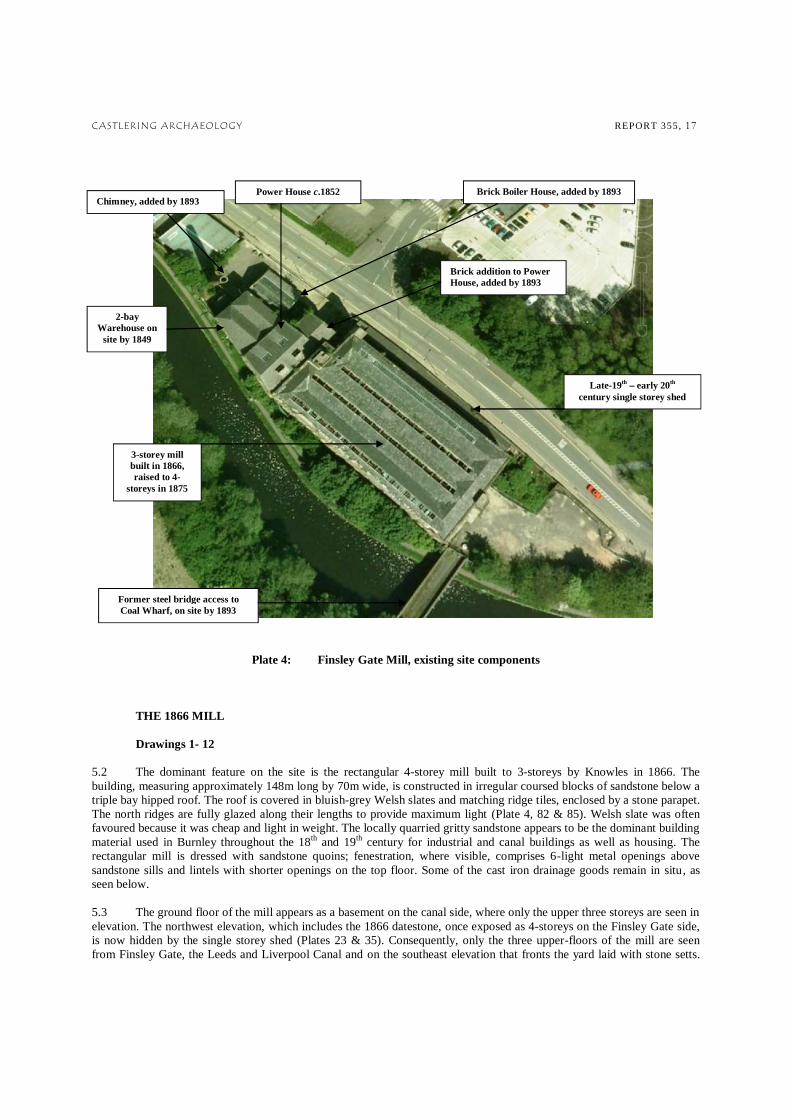
Plate 4: Finsley Gate Mill, existing site components
THE 1866 MILL Drawings 1- 12 5.2 The dominant feature on the site is the rectangular 4-storey mill built to 3-storeys by Knowles in 1866. The building, measuring approximately 148m long by 70m wide, is constructed in irregular coursed blocks of sandstone below a triple bay hipped roof. The roof is covered in bluish-grey Welsh slates and matching ridge tiles, enclosed by a stone parapet. The north ridges are fully glazed along their lengths to provide maximum light (Plate 4, 82 & 85). Welsh slate was often favoured because it was cheap and light in weight. The locally quarried gritty sandstone appears to be the dominant building material used in Burnley throughout the 18th and 19th century for industrial and canal buildings as well as housing. The rectangular mill is dressed with sandstone quoins; fenestration, where visible, comprises 6-light metal openings above sandstone sills and lintels with shorter openings on the top floor. Some of the cast iron drainage goods remain in situ, as seen below. 5.3 The ground floor of the mill appears as a basement on the canal side, where only the upper three storeys are seen in elevation. The northwest elevation, which includes the 1866 datestone, once exposed as 4-storeys on the Finsley Gate side, is now hidden by the single storey shed (Plates 23 & 35). Consequently, only the three upper-floors of the mill are seen from Finsley Gate, the Leeds and Liverpool Canal and on the southeast elevation that fronts the yard laid with stone setts.
Chimney, added by 1893 Power House c.1852
2-bay Warehouse on
site by 1849
3-storey mill built in 1866, raised to 4-
storeys in 1875
Former steel bridge access to Coal Wharf, on site by 1893
Late-19th early 20th century single storey shed
Brick addition to Power House, added by 1893
Brick Boiler House, added by 1893

CASTLERING ARCHAEOLOGY REPORT 355, 18
Three storeys of regularly spaced windows light the first to third floors and divide the 1866 Mill into 18 bays along its long axis. 5.4 The southeast elevation rises to three storeys with a central narrow lift tower that formed part of the original building (Plate 34). The continuous stone band shows where the mill was raised in height in 1875 and a further addition has been made to the lift tower in more modern times. The third bay from the northeast includes loading doors and an overhanging hoist, acknowledging the late 19th century legislation that prevented Burnley mill owners from having their hoists overhanging the streets. 5.5 Southeast of the 1866 Mill, iron railings form a boundary with the canal and Finsley Gate, enclosing the yard area. On the south side of the yard, a pair of iron gates leads to the steel framed bridge that once linked the mill to the Coal Wharf and, from the Lambert and Butler period, to Healey Royd Mill complex (Plates 39-41). On the northwest corner of the mill, the rendered tower encloses the lift shaft added in 1950 (Plates 34 & 35). Plate 5: cast iron downspouts & light fitting Plate 6: 1866 Mill column style on the southwest elevation
1866 MILL INTERIOR 5.6 The 1866 Mill, like most mills, was constructed around the principle of rectangular design with floors supported by cast iron columns. The mill is not of fireproof construction, although it was built in a period when fireproof technology had become widely adopted. Joisted planked floors are supported by 16 deep (0.4m) primary wooden beams that rest on c (0.5m) thick stone outer walls and are supported at intersections by the four rows of 18 cylindrical cast iron columns that run down the long axis of the mill, separating all four floors into four almost equal bays. The style and layout of the columns is repeated on all floor levels. The rolled and winged heads of the columns bolt to the beams above (Plate 6 previous). The columns are not vertically connected; timber floors are sandwiched between each level of column. The ground, first and second floors of the mill have concrete screed floors while the top floor has a stripwood floor, probably laid over the original planks. The stripwood floor has been considerable damaged by the incursion of rainfall into the top floor (Plates 82 & 83 following).

CASTLERING ARCHAEOLOGY REPORT 355, 19
5.7 The form of mill buildings was dictated by the processes they contained. The machinery was supplied by steam power with a main upright shaft forming the link between the engine and the central drive shafts that ran the length of the mill on all floors. The flat bolting holes in the columns indicate how the belt drives from the line shafting above were transferred to the machinery. Within the existing building, however, there is no longer any surviving floor evidence of the position of the machinery. 5.8 All internal bricks measure 230 x 100 x 70mm. The upper floor of the mill is open to the roofline where additional light is provided by the north facing glazing. The triple roofline is supported by King-post trusses with raking struts (Plate 84). On the southeast end of the top floor, machinery to take goods towards the narrow lift shaft and the hoist bear the
E. A. Foulds Ltd Colne, Lancashire, seen below. The company was established by Ernest Albert Foulds in 1907 as a general engineering and millwright business, to serve the needs of the local textile industry; later focussing on the manufacture of lifts and hoists. Plate 7: 5.9 The main entrance is from the southeast elevation, alongside the narrow lift shaft, where a wide dog leg concrete staircase, enclosed by insulation board, rises to the upper three floors. A single flight of wooden steps leads down to the former ground floor, which was open to Finsley Gate prior to the addition of the single storey shed. The shed now encases the floor like a basement, the north side of which is built against the canal bank. On the west side of the 1866 Mill, the stone staircase enclosed by rubblestone appears to have been part of the earlier mill on site. A further dog-leg staircase is located on the southwest side of the building at the east end. THE NORTHEAST END OF THE 1866 Mill 5.10 The northeast side of the 1866 Mill is separated from the Power House by a 0.6m thick wall constructed in red sandstone rubble. The wall is not faced on the outer elevation of the Power House, indicating that this was never an exposed wall. The rubblestone is continuous around the square stone staircase on all floor levels and visible in the dog-leg staircase on the southwest side of the mill, where access is possible (Plates 55 & 60). The rubblestone appears to have once formed the east wall of the 1820s Turn Bridge Mill. The wall was retained when the House was added to the site in the 1850s and the wall was not replaced during the construction of the new mill in 1866. Viewed from the air (Plate 4 previous), it is clear that the roof of the 1866 Mill was designed to extend over the earlier staircase towards the Power House wall. 5.11 The internal measurement of the rubblestone wall is c.9.4m, which suggests that the width of the 1820s Turn Bridge Mill corresponds to the 30ft factory width recommended by Arkwright in the late 18th century. The full-height stone staircase was presumably an external feature of the 1820s mill.

CASTLERING ARCHAEOLOGY REPORT 355, 20
THE POWER HOUSE Drawings 1-12 5.12 The three-storey building adjoining the northwest side of the 1866 Mill is the Power House, built shortly after the 1852 explosion to continue to drive machinery for Turn Bridge Mill. The building is constructed in coursed square sandstone rubble with dressed quoins encircled by a first floor lintel band. The building is aligned southwest-northeast with gable ends fronting the canal to the south and facing Finsley Gate to the north. The north elevation is masked by the late-19th century red-brick addition (Plates 27 & 28 following), which was presumably added at the same time as the chimney and the boiler house. 5.13 The blocked opening in the canalside elevation at ground level, seen below and recorded on Drawing 7, may indicate how the flue to the first chimney on site left the Power House. Plate 8:
Blocked opening in the canalside elevation
5.14 The lower courses of the Power House northeast gable wall have been removed and the ground floor is now open towards the modern loading door in the red brick addition that protrudes 5m in front of the stone-built Power House. Parts of the original features of the northeast elevation of the House can be seen in the upper floors of the red-brick frontage, where they have been either painted over or panelled as offices were required in more recent times (Plate 46). In the east bay, a tall opening measuring 2.5m high to the keystone by 1.5m wide is painted over (Plate 47). The small opening above it looks into the roofspace described in 5.19 following. To the rear, the entire southwest elevation of the House can be seen from the canal (Plate 81 & Drawing 7 following). SOURCE OF POWER 5.15 The Power House is divided into two longitudinal bays with the two thickest walls of 0.7m being on the west side (Drawings 1-4). This would suggest the location of a steam engine. The flight of narrow wooden steps that rise from this bay appear to be original and in quite a restrictive position. They are clearly only intended for use in servicing the engine. The tall openings in the western bay have segmental heads, following the general trend of openings used in engine houses. 5.16 A machinery would be the most likely choice in the mid-19th century period. Steam may have been originally provided by a type of wagon boiler advocated by the Boulton and Watt partnership, housed in the eastern compartment. After the new larger mill was built in 1866, more power would have been required. In the later 19th century, a new horizontal engine may have been introduced, fed by steam provided by the three Lancashire boilers sited in the purpose-built red brick Boiler House added on the Finsley Gate side of the warehouse (Drawing 1; paras 5.20-5.26 following). The Lancashire boiler (patented by William Fairburn & John Hetherington in 1844) with double-flues became the standard boiler used in cotton

CASTLERING ARCHAEOLOGY REPORT 355, 21
mills from the mid-19th century period, replacing the less powerful wagon boilers. Either type of engine would have transferred power from the engine flywheel and gear drive to the mill machinery by a series of horizontal drive shafts. 5.17 There is little evidence of steam power visible within the Power House today. Only one cast iron bearing box (Plate 9 below left) was evident in the internal east wall of the Power House at second floor level and a section of steam pipe was located to the west side of the red-brick of the House at ground floor level, which may have connected to the boilers (Plate 10 below right). 5.18 The building has been considerably altered by the introduction of a more modern electric power system by Lambert Howarth since the 1950s. The early mill was presumably lit by gas lighting supplied by the nearby gasworks until electricity was introduced. The Lambert Howarth factory was entirely powered by electricity and the main power supply, which is still active and until recently served other properties along Finsley Gate, is sited in a sealed compartment in the single storey shed, as indicated on Drawing 1.
Plate 9 left & Plate 10 above POWER HOUSE ROOFSPACE 5.19 The floor of the present roofspace is unsafe, but the area can be seen from the ramped access that descends c.1m down from the top floor of the mill (Plate 53). The roof is now supported by a lightweight bolted steel frame inserted into the stone long walls (Plates 50-53 & Drawing 4). The frame may follow the style of the original frame, constructed in cast and wrought iron, as seen by the author on mid-19th century industrial buildings. The frame, built on a complicated pattern of queen posts and angled struts with iron tie-rods, has fireproof qualities while providing ample space for the numerous pipes that run through the building at this level. The cast and wrought iron frame may have been used as a pre-fabricated structure, individually designed to fit the space between the 1820s Turn Bridge Mill and the 1848 Warehouse. The regular coursing in the former 1820s external sandstone wall is clearly seen in Plate 47; the stones measure a fairly consistent 11 x

CASTLERING ARCHAEOLOGY REPORT 355, 22
THE EXTERNAL BOILER HOUSE 5.20 The boiler house is a rectangular single-storey gable-ended structure sited close to the former engine and the present chimney. The late 19th century boiler house is aligned northwest-southeast below a slate roof with north facing lights, supported by a steel frame. The elevation fronting Finsley Gate is fully rendered and three staggered 0.6m wide segmental headed openings are located in the northwest gable above the rendered ground level (Plates 27 & 29). 5.21 Over periods of modernisation steam powered machinery was superceded by electricity, while the three boilers continued to be used for the supply of heating. The boiler house has been sealed up since the survey undertaken in 2004 and the three Lancashire boilers and their associated fittings survive on the site, although fairly inaccessible due to the condition of the building. Internally three Lancashire boilers are arranged longitudinally. The two northernmost boilers are coal fired while the southern boiler has been converted to oil consumption in the post-1959 period, perhaps in anticipation of a coal shortage s on the boilers but the two coal- (5.22 following). 5.22 The boilers are housed in brick casings which enclosed their surrounding brickwork flues. The brick flues allowed for the hot gases produced by burning coal to circulate under and along the sides of the boilers before exiting towards the external chimney. The lingering hot gases also helped to heat the water in the boiler. The boilers measure a linear 30ft in length by 9ft diameter, built in riveted steel. Plate 12 below shows how the furnace doors have been removed when the oil feed was added and Plate 11 below shows the twin-furnace doors fitted with the stoker feeds. Only the top of the boilers are visible; some of the fittings are retained, although damaged, and asbestos cladding is dispersed over the boiler house floor (Plate 14 overleaf). The charging ends of the boilers protrude from the white tiled wall on the northwest side of the house seen below.
Plate 11: Middle of the 3 boilers Plate 12: The southern boiler fitted with an oil supply
Safety valves

CASTLERING ARCHAEOLOGY REPORT 355, 23
5.23 James Proctor was an engineer, born in 1836, who developed the idea for stoking boilers automatically, resulting in the first patent for his invention taken out in 1875 named `Proctor`s Mechanical Stoker`. Numerous improvements followed and the company registered as James Proctor Ltd. in June 1902 continues to manufacture modern automatic feeds today. The stoker is primarily constructed in cast iron and fed from the coal feed above. There is no coal hopper evident and no obvious coal storage on the site, although evidence may be sealed below the present yard surface. The coal would fall into
ed inside the 'Ram Coking Stoker' box. The activating lever for the ram is on the left hand-coal down onto cast iron coking plates within the charging hole. The coking plates reached a red hot temperature which coked the coal, driving off unwanted gases.
Plate 13:
5.24 The high temperatures reached within the boilers required the fitting of steam valves in order to release excess steam. Plate 14 below shows the blue stop valve (a crown valve) which could isolate the boiler and its pressure from the mill / factory plant. The hand wheel indicates a type of screw-down valve fitted to the eastern / oil fired boiler. The higher west side of the boiler house and the topside of the boilers are reached by an unstable set of wooden steps and a gangway that rests on top of the boiler housing on the south side (Plate 88 following). 5.25 The boilers were presumably fed with water either directly from the town's water mains or from the canal. 5.26 The boilers are recorded in plan on Fig. 1 and further investigations are prevented by the current state of the building and the presence of asbestos.
Plate 14:
The tops of the 3 boilers protruding above the brick housing
Low water safety valves

CASTLERING ARCHAEOLOGY REPORT 355, 24
1848 WAREHOUSE
5.27 The Warehouse appears to have been added in 1848 to serve the 1820s Turn Bridge Mill. The 1849 OS record shows a link alongside the canal between the mill and the warehouse but the existing canalside elevation of the Power House indicates that this link must have been demolished in favour of building the new Power House in the 1850s. The warehouse is an example of a fireproof building construction, which together with the remains of an overhead sprinkler system on both floors suggests it may have been originally used to store the bales of cotton off-loaded from canal barges. The canalside loading doors in the southwest elevation are seen in Plate 32. Additional loading doors face into the yard (Plates 31 & 33 following). The stone features on the canalside elevation indicate that this was once the principle elevation of the building. 5.28 The upper two floors show the original layout. At first floor level, the space is subdivided by a single row of four
cylindrical cast iron columns with rolled heads that support five springing from iron plates which seem to be cast in a single piece (Plates 15 below & 62-65 following). Each arch spans a 6ft wide roof section. The floors are now covered with a concrete screed, but the original form would have been flagstones, separated from the jack-arches below by a fill of sand or ash. 5.29 A single flight of iron railed steps rise to second floor level, where the line of columns is repeated (Plates Plate 16 below & 66-70). The second floor columns are winged to support the roof trusses above. The opening in the south side of the internal wall (Plate 71) may have provided access from the 1820s mill, as suggested by the 1849 OS map (Fig. 4 previous). Elsewhere throughout the site several original openings have been altered and / or enlarged in the intervening walls, to allow free access between the buildings. Plate 15 far left:
Sample ground floor column Plate 16 left: Sample ground floor column & hoist machinery

CASTLERING ARCHAEOLOGY REPORT 355, 25
LATE 19TH CENTURY RED-BRICK BUILDINGS
Elevation Drawing 5 5.30 The brick Chimney, Boiler House and three-storey front to the Power House are all constructed in red bricks. While the bricks used on the boiler house and the front to the Power House measure a standard 230 x 100 x 70mm, those used on the chimney are larger measuring 230 x 110 x 75mm. The free-standing chimney, bound by 11 iron bands, is the westernmost feature on the site. The size of Lancashire boilers necessitated the construction of an external boiler house, the scale of which was determined by the number of boilers. THE SINGLE STOREY SHED
Drawings 1 & 5 5.31 The single storey shed flanks the 1866 Mill and fronts Finsley Gate (Plates 17 & 18 below & 23 & 24 following). Cartographic evidence suggests the linear structure may have been built in two phases; the west side completed by 1893 and the east by 1912. The street frontage elevation now comprises four blocked openings and a modern wooden door leading in off the street. The shed now houses a modern plant room and electricity sub-station to which there is no access (Plate 17 below). Access to the shed from the ground floor of the mill was sealed with concrete blocks sometime after 2007, both to prevent unlawful access and because of the presence of asbestos. The view from above the mill floors above shows how slates have been robbed from the roof in attempts to gain access. Plate 17 above: Blocked access to modern plant room and electricity sub-station Plate 18 right: Damaged roof seen from above
5.32 In October 2011 access to the interior of the shed was gained through the former blocked access. The plan of the shed is recorded on Drawing 1 which shows how the former plant / power room on the east side of the building has been converted to a toilet. South of this, the east side of the shed forms one open space with no evidence of its past use. Plate 19 overleaf shows how the shed has been abutted to the ground floor of the 1866 mill. The east and west sides of the building are separated by the electricity sub-station, which is still in use and only accessible from the door seen in Plate 17 above.

CASTLERING ARCHAEOLOGY REPORT 355, 26
5.33 The west side was last used as a couple of small storage spaces that adjoined the lift shaft sited in the northwest angle of the 1866 mill. The ancillary hand-winder for the lift shaft, manufactured by Colnes, is in situ in an alcove adjoining the east side of the lift (Plates 21 & 22 below).
Plate 19 above: East end of the shed, viewed from the west
Plate 20 left: Ground floor lift access Plate 21 left: Ancillary hand-winder & Plate 22 below: operating instruction

CASTLERING ARCHAEOLOGY REPORT 355, 27
6 . PHOTOGRAPHIC ILLUSTRATION
Plate 23 above: Mill viewed from the east across Finsley Gate (June 2007) Plate 24 left: Mill viewed from the northwest, with the late-19th century chimney rising above the site (June 2007)

CASTLERING ARCHAEOLOGY REPORT 355, 28
Plate 25 left: Mill viewed from the northwest, alongside the canal (June 2007) Plate 26 below: Southeast elevations of the Mill, viewed from Healey Royd Mill (January 2009)

CASTLERING ARCHAEOLOGY REPORT 355, 29
Plate 27: Power House built c.1852 & Warehouse built c.1848 with late-19th century red-brick additions, viewed from the north across Finsley Gate (April 2011) Plate 28: The northeast gable of the 3-storey Power House masked by the late-19th century brick addition to the front; (June 2007)
3-storey Warehouse
3-storey Power House
Late-19th century Boiler House & front
to Power House

CASTLERING ARCHAEOLOGY REPORT 355, 30
Plate 29 above:
Late 19th century Boiler House, northwest elevation Plate 30 left: Late-19th century Chimney (June 2007)

CASTLERING ARCHAEOLOGY REPORT 355, 31
Plate 31: The northwest elevation of the Warehouse, built mainly in brick,
& the southwest elevations fronting the canal (April 2011) Plate 32 left: Warehouse, canalside elevation, Plate 33 right: Warehouse, northwest
former loading doors & hoist (April 2011) elevation, loading doors & hoist (June 2007)

CASTLERING ARCHAEOLOGY REPORT 355, 32
Plate 34: 1866 Mill, southeast elevation with lift shaft and hoist over former loading doors (April 2011) Plate 35: View from the southeast over the single storey-shed: 1866 Mill northeast elevation picture left & in the background the rendered lift shaft added in 1950 (June 2007)

CASTLERING ARCHAEOLOGY REPORT 355, 33
Plate 36: Former footbridge over the canal connecting the first floor level of the former Healey Royd Mill to the third floor of Finsley Gate Mill (June 2007)
Plates 37 & 38: Views over the footbridge seen during demolition work at Healey Royd Mill (January 2009)

CASTLERING ARCHAEOLOGY REPORT 355, 34
Plate 39 above: The late-19th century steel bridge that linked the former Coal Yard to Finsley Gate Mill
& Plates 40 & 41 below: Bridge viewed from the south and the north

CASTLERING ARCHAEOLOGY REPORT 355, 35
Plate 42: The single-storey shed fronting Finsley Gate Plate 43:
Brick additions to facilitate toilet facilities and corridors

CASTLERING ARCHAEOLOGY REPORT 355, 36
POWER HOUSE INTERIOR
GROUND FLOOR
Plate 44 left: View from the southwest towards the modern sliding doors inserted into the
late-19th century front to the Power House
&
Plate 45 right: View from the northeast towards the much-altered ground floor of the Power House

CASTLERING ARCHAEOLOGY REPORT 355, 37
SECOND FLOOR OF LATE 19TH-CENTURY BRICK ADDITION TO THE NORTHEAST GABLE OF THE POWER HOUSE
Plate 46: View towards sections of the external sandstone wall of the Power House exposed in the east bay of the late-19th century brick addition
Plate 47: External sandstone wall
of the Power House exposed in the west bay of the late-19th century
brick addition to the front of the House

CASTLERING ARCHAEOLOGY REPORT 355, 38
FIRST FLOOR OF THE POWER HOUSE
Plate 48: The west bay of the Power House at second floor level; the conveyor belt runs through to the east bay seen below left
Plate 49: East bay through to west bay

CASTLERING ARCHAEOLOGY REPORT 355, 39
TOP FLOOR OF THE POWER HOUSE
Plate 50: View towards the northeast gable
Plate 51: View towards the northwest wall

CASTLERING ARCHAEOLOGY REPORT 355, 40
Plate 52: View towards the southwest gable, Plate 53: View from the ramped access into (canalside) the Power House towards the top floor of the 1866 Mill Plate 54: View towards the wall between the Power House and the 1866 Mill; the coursed sandstone represents the outer wall of the 1820s mill

CASTLERING ARCHAEOLOGY REPORT 355, 41
P0WER HOUSE EXTERNAL SOUTHEAST WALL
& EVIDENCE OF TURNBRIDGE MILL
1866 Mill TOP (4th) FLOOR, NORTHWEST END Plate 55: View towards the southeast wall of the Power House; the rubblestone represents the internal wall of the 1820s Turn Bridge Mill
Plate 56:
View from the southwest towards the sandstone wall enclosing the flight of stone steps that also
served the old Turn Bridge Mill

CASTLERING ARCHAEOLOGY REPORT 355, 42
1866 Mill 3rd FLOOR, NORTHWEST END
Plate 57: View towards the southeast wall of the Power House: former internal wall of the 1820s Mill and, to the
right, the sandstone wall that encloses the flight of stone steps, also part of the 1820s Mill
Plate 58:
Wall enclosing flight of stone steps, viewed from the southwest

CASTLERING ARCHAEOLOGY REPORT 355, 43
Plate 59: External southeast rubble wall of the Plate 60: Southeast wall of the Power House Power House, abutted by the 1866 Mill at first floor level; View from 3rd down to 2nd floor modern staircase former northwest wall of the 1820s Mill
1848 WAREHOUSE
GROUND FLOOR FORMER LAMBERT HOWARTH FACTORY SHOP Plate 61: View towards the north

CASTLERING ARCHAEOLOGY REPORT 355, 44
1848 FIREPROOF WAREHOUSE FIRST FLOOR
Plate 62: View towards the northeast wall; steps rise to second floor
Plate 63: View towards the northwest wall, loading door & steps to second floor

CASTLERING ARCHAEOLOGY REPORT 355, 45
Plate 64: View towards the concrete blocked openings in the canalside wall to the southwest
Plate 65 above: Brick jack-arch detail; view towards the northeast wall Plate 66 right: Flight of iron railed steps to top (third) floor

CASTLERING ARCHAEOLOGY REPORT 355, 46
1848 FIREPROOF WAREHOUSE TOP (THIRD) FLOOR
Plate 67: View towards the openings and former loading door in the canalside wall to the southwest
Plate 68: View towards northeast wall with enclosed steps and the machinery for transporting goods to and from the loading door in the northwest wall

CASTLERING ARCHAEOLOGY REPORT 355, 47
Plate 69: View from the southeast towards the Plate 70: as left, viewed from the south loading door and overhead machinery
Plate 71: View from the northwest towards the large opening that now leads to the canalside section of the former Power House

CASTLERING ARCHAEOLOGY REPORT 355, 48
1866 Mill GROUND FLOOR
Plate 72: Mill former ground floor, blocked on the northeast side by the addition of the single storey shed:
view from the southeast towards the four internal bays separated by rows of 18 cast-iron columns
Plate 73: Column and beam supporting wooden floor above; underside of the flight of wooden steps picture left

CASTLERING ARCHAEOLOGY REPORT 355, 49
1866 Mill FIRST FLOOR
Plate 74: View from the southeast
Plate 75: Column and beam supporting wooden floor above

CASTLERING ARCHAEOLOGY REPORT 355, 50
1866 Mill SECONDFLOOR
Plate 76: View from the east
Plate 77: View from the southeast; supportive bracing in place between the columns to the right

CASTLERING ARCHAEOLOGY REPORT 355, 51
Plate 78: Views towards the west end of the mill; the conveyor belt formerly ran across the bridge over the canal, seen in Plates 36-38, to connect to Healey Royd Mill
Plate 79: View from the northeast towards the conveyor belt run & former link to the bridge

CASTLERING ARCHAEOLOGY REPORT 355, 52
Plate 80: Location of former foot bridge to Healey Royd, seen in the blocked openings on the canalside elevation (April 2011)
Plate 81: Blocked openings and canalside elevation seen from Healey Royd Mill
(January 2009)

CASTLERING ARCHAEOLOGY REPORT 355, 53
1866 Mill TOP (THIRD) FLOOR
Plate 82: View from the southeast towards the two northernmost bays
Plate 83: View from the southeast towards the two southernmost bays
CASTLERING ARCHAEOLOGY REPORT 355, 54
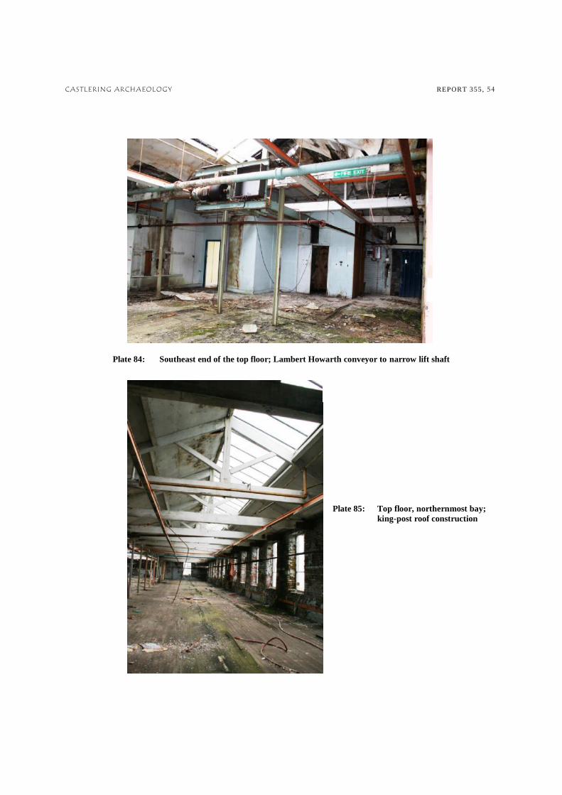
Plate 84: Southeast end of the top floor; Lambert Howarth conveyor to narrow lift shaft Plate 85: Top floor, northernmost bay; king-post roof construction

CASTLERING ARCHAEOLOGY REPORT 355, 55
BOILER HOUSE INTERIOR
Plate 86 left:
The three boilers protruding west from the brick housing, view from the south
Plate 87 below: The southernmost oil-fired boiler, viewed from the east
Plate 88 below left: Southernmost boiler & access steps to housing

CASTLERING ARCHAEOLOGY REPORT 355, 56
Plate 89 above: The middle of the three boilers, viewed from the northeast
Plate 90 left:
Coal-fired boilers with coke feeders, viewed from the southwest

CASTLERING ARCHAEOLOGY REPORT 355, 57
7 . SURVEY DRAWINGS , A PRIL 2004
DRAWING 1: GROUND FLOOR PLAN DRAWING 2: FIRST FLOOR PLAN DRAWING 3: SECOND FLOOR PLAN DRAWING 4: THIRD FLOOR PLAN DRAWING 5: DRAWING 6: DRAWING 7: DRAWING 8: ELEVATION DRAWING 9: SECTION A-A DRAWING 10: SECTION B-B DRAWING 11: TOPOGRAPHICAL SURVEY DRAWING 12: ROOF SURVEY

CASTLERING ARCHAEOLOGY REPORT 355, 58
8 . DISCUSSION
8.1 While Finsley Gate Mill is one of the many steam-powered purpose-built manufactories built to house the growing 19th century cotton industry in Burnley. The mill has not fulfilled the current criteria for Listed building status by English Heritage, however it is nevertheless considered to be of sufficient historical, architectural and industrial archaeological interest to warrant the current programme of work. 8.2 The current work has shown that the mill remained constantly in use for over 150 years until purchased by Lambert Howarth in 1959. The buildings are part of a changing landscape where many old industrial buildings have been replaced by modern workshops and retail units. The mill itself exhibits five building phases illustrating the rise of the cotton industry in the town, changes and improvements in technology, the final decline of the cotton industry and the introduction of new manufacturing processes into the site. The history of the mill is closely linked to three local families, the Holgates, Knowles and Withams, household names in the cotton industry in their time. 8.3 Finally the mill came into the hands of Lambert Howarth and since 1959 their commercial success in supplying goods to Marks and Spencers, another household name, saw major internal alterations to the site, brought about by the change of use, the introduction of different type of machinery and the requirements of more office space and toilet facilities. The canalside became less of an asset as goods became more easily moved by road as opposed to by canal boat. 8.4 There is little surviving architectural interest within the mill buildings themselves other than their basic construction features. The cast iron columns and jack-arches in the c.1848 Warehouse bear testimony to the move towards fireproof technology in the 19th century; while Knowles 1866 mill represents a preference for cast iron columns and treated wooden beams. The former engine house retains no machinery and has been impacted on by the brick addition to its frontage. 8.5 Of more interest are the three late-19th century Lancashire boilers that survive within the external boiler house, which served the Mill and the Lambert Howarth factory for in excess of 100 years. Their survival is due to their continued use for heating on the site during the Lambert Howarth period and, after this company folded, their size and their setting presumably prevented them from being sold along with the other machinery on the site. 8.6 Since Lambert Howarth moved out and the complex fell out of use, the mill has been vulnerable to vandalism, slates have been stolen from the roof, people have slept rough in the building and fires have been started. In the interests of safety and in attempts to prevent further vandalism, the lower openings in the mill buildings were blocked off. Over the years rainwater has ingressed and pooled on most of the floors. Consequently the building has become unsafe. 8.7 While the external elevations of the mil have been recorded since 2007, access to the interior has only recently been gained. Access has been limited in the interests of health and safety given the deteriorating condition of the site and the presence of asbestos. However, the current programme of work and the plans undertaken by Tower Surveys in 2004 have ensured that a record has been made of the existing site prior to any demolition and subsequent redevelopment, which may take place.
9 . ACKNOWLEDGEMENTS
Castlering Archaeology would like to express gratitude to the following for their valuable help during the project: St Modwen Properties PLC. for contracting the recording work; Prosurv Consult PLC; Tower Surveys, Chartered Surveyors, Nottingham for the detailed surveys drawings; John Rutter of RFS Consultancy, Whitchurch, for accompanying the internal site visit in April 2011 and Martin Kettle for doing the same in October 2011; Drivers Jonas Deloitte, Surveyors and Planners; Doug Moir, Planning Officer (Archaeology), Lancashire County Archaeology Service; and staff at Burney Library Local History Section and Lancashire County Record Office, Preston.

CASTLERING ARCHAEOLOGY REPORT 355, 59
10 . SOURCES
10.1 Bibliography Ashmore O., 1969, The Industrial Archaeology of Lancashire. Newton Abbot Ashmore O., 1982, The Industrial Archaeology of North-West England. Manchester Bennett W., 1949, The History of Burnley 1650 to 1850, Part 3. Burnley Bennett W., 1951, The History of Burnley from 1850, Part 4. Burnley Chapples L., 1992, My Burnley Memories. Burnley Clarke M., 1990, The Leeds and Liverpool Canal; A Historical Guide. Leeds DoE, 1990, Planning Policy Guidance Note 16: Archaeology and Planning (PPG 16), London: HMSO DoE & DNH, 1994, Planning Policy Guidance Note 15: Planning and the Historic Environment (PPG 15), London: HMSO Department for Communities and Local Government, 2010, Planning Policy Statement 5: Planning for the Historic Environment. March 2010, London: TSO (www.communities.gov.uk/documents/planning) Farrer W. & Brownbill, J., 1911, The Victoria History of the County of Lancaster, 6, London Grant J., 1887, A Sketch of Burnley Seventy Years Ago, Transactions of the Burnley Literary and Scientific Club, 5, 94-105 Hall B., 1977, Burnley (A Short History), Burnley (Burnley Library) Hall B., & Spencer K., 1993, Burnley, A Pictorial History, Chichester Howell J., nd, Hills R.L., 2008, Development of Power in The Textile Industry. Landmark Publishing Ltd. IfA, 1997, Code of Conduct (revised 2009) IfA, 2001, Standard and Guidance: For Archaeological Desk-Based Assessment. Reading (revised edition) IfA, 2001, Standard and Guidance: For the Investigation and Recording of Standing Buildings or Structures. Reading (revised edition) RCHME, 2006, Recording Historic Buildings A Descriptive Specification. 3rd edition Lancashire County Council & Egerton Lea Consultancy, 2005, Lancashire Historic Town Survey Programme: Burnley; Historic Town Assessment Report; published by Lancashire County Council & Egerton Lea Consultancy with the support of English Heritage & Burnley Borough Council. May 2005 Leask, Andrew, W., 2007, Report on Finsley Gate and Healey Royd Mills, Burnley (Structural). D05/128, Rogers Leask Ltd., June 2007 Leask, Andrew, W., 2007, Updated Report on Finsley Gate and Healey Royd Mills, Burnley (Structural). Rogers Leask Ltd., December 2008

CASTLERING ARCHAEOLOGY REPORT 355, 60
Lewis, David W., 2007, Conservation Area Consent Application and Planning Application: Finsley Mill and Healey Royd Mill, Supporting Justification Statement. David Lewis Associates, January 2007 Lowe J., 1985, Burnley. Chichester Nadin, Jack, nd, (Burnley Library; pub. by author) Nadin, Jack, 2008, Burnley Cotton Mills. Tempus Rutter, John, 2011, Finsley Gate, Burnley, Lancashire: Asbestos Survey Report. RFS Consultancy, Whitchurch: March 2011 Slater D.J., 1987, Burnley and the Textile Industry, unpub. BA dissertation, Liverpool Polytechnic Smith S., 1970, The Leeds and Liverpool Canal: the Waterway that made Burnley Prosperous. Burnley Timmins G., 1996, Four Centuries of Lancashire Cotton. Preston Townend M., 1999, Burnley: Images of England. Stroud 10.2 Trade Directories
of Lancashire. Manchester 1855, Mannex & Co. History, Topography, and Directory of Mid-Lancashire. Preston 1868, Mannex & Co. Directory of North and East Lancashire etc. Preston 1876, Mannex & Co. Directory and Topography of North-East Lancashire with Bury and District. Preston 1918, 1927, Burnley Guide; Chamber of Commerce
y 10.3 Cartography 1827 Plan of the Town of Burnley by Fishwick (Burnley Library) 1841 Plan of the Town of Burnley by Merryweather (Burnley Library) 1848 Burnley Tithe Map (LRO DRB 1/31)
1851 OS 1:500 town map, surveyed 1949, Sheet 8 1893 edition s 64.2 & 64.6 1910 Old Ordnance Survey Maps, Godfrey Edition Burnley 1910, Lancashire Sheet 64.02 1912 s 64.2 & 64.6
1938 edition OS 1: 10560 map, Lancashire sheet 64 NE 1960 edition 1:2500 map 10.4 Burnley Library Burnley Advertiser, 1857, viii, 290 p.2 c.1 re. Finsley Gate to let Burnley Gazette, 1866, iii, 10 p.3 c.7 re. fire Burnley Express 1939, III, 22, p8, c3 re. Lambert Howarth take over Acc.no. 10167: The Decline of the Cotton Trade in Burnley by Sr Elizabeth. 1959 Thesis, University of Belfast

CASTLERING ARCHAEOLOGY REPORT 355, 61
10.5 Websites www.burnley.gov.uk www.maplandia.com www.spinning the web.com www.weaverstriangle.co.uk www.google-earth 10.6 Lancashire Historic Environment Record PRN 22067 Healey Royd Mill, Hughes Street, Burnley post 1848. Recorded by OS in 1897 PRN 22068 Post-1848 Coal Depot, adjacent to Leeds & Liverpool Canal, north of Marlborough Street PRN 6875 Cotton Factory between Finsley Gate and the Leeds Liverpool Canal shown on the OS first edition map PRN 16970 Finsley Gate Boatyard, Burnley; former Finsley Gate wharf boatyard Warehouse, now a workshop and offices. Grade II
Listed building no. 906-1-3-55 PRN 16971 Former Finsley Gate Boatyard; 18th century canal bridge operator's house now a workshop on the east side of the British Waterway's Yard. Grade II Listed building no.906-1-3-56 PRN 22069 Finsley Dockyard, adjacent to Leeds & Liverpool Canal

CASTLERING ARCHAEOLOGY REPORT 355, 66
Appendix 1A SPECIFICATION FOR ARCHAEOLOGICAL RECORDING OF FINSLEY GATE AND HEALEY ROYD MILLS, FINSLEY GATE, BURNLEY (SD 8411 3203) Prepared on behalf of Burnley Borough Council for Mr Nicholas Whittingham, Land Director, St Modwen Properties PLC 1. Summary 1.1 Planning permission (12/07/0042) for mixed-use development including residential, office, leisure (use classes A3, A4, C2, C3, D1, D2, B1 & B2) and associated car parking, and Conservation Area Consent (12/07/0043) for the demolition of the card room along Finsley Gate frontage and 20th Century extensions to north and west. Healey Royd Mill: demolition of 2 bays of single storey cutting sheds and demolition of post-1930 extensions at Finsley Gate and Healey Royd Mills Burnley has been granted by Burnley Borough Council. Because of the historic nature of the site it has been recommended that an archaeological record of the buildings should be made. 1.2 This recommendation follows the advice given by central government as set out in Planning Policy Guidance: Planning and the Historic Environment (PPG 15) and Planning Policy Guidance: Archaeology and Planning (PPG 16) issued by the DoE. 2. Site Location and Description 2.1 The site is located at NGR SD 8411 3202, bounded by Centenary Way (A682) to the north, Finsley Gate to the east, Springfield Road to the south and Marlborough Street and Healey Wood Road to the west. The site is bisected by the Leeds and Liverpool Canal, with Healey Royd Mill to the west and Finsley Gate to the east. The site does not currently have any electricity supply, and contractors will therefore need to provide their own lighting. Some vandalism of the site has occurred leaving some trip hazards and broken glass. The roofs are in a fair state and although pigeons have nested in the buildings there is only a limited amount of pigeon guano. Both mills are thought to have been completely cleared of any surviving machinery, although access to the Finsley Gate Boiler House was not possible. 3. Planning Background The proposed development will require the demolition of the 20th century card room, as well as 20th century extension to Finsley Gate Mill, as well as single storey cutting sheds and post-1930 extensions on the Healey Gate Mill side of the site.
ithin Zone B, D and E until the developer has secured the implementation of a programme of recording of buildings in that Zone, in accordance with a written scheme of investigation, which has been submitted to and approved in writing by the Local Planning Authority. A
After a site visit with Mr Whittingham it was agreed that a staged approach to the recording would be followed, comprising: 3.3.1 A general photographic record of the site as it currently exists prior to any demolition works. No drawings will be required for this stage. (This does not apply to the 1903 card room which will require a detailed drawn and photographic record before it can be demolished). 3.3.2 The mills will then be subject to a soft strip which will see the removal of modern material such as office partitions and suspended ceilings. After this has been completed the archaeologists will return to site to complete a detailed photographic and drawn record of the buildings. 3.3.3 The developer is considering developing the site is a stage manner, commencing with the Healey Royd complex and then moving on to the Finsley Gate site. It is therefore possible that the recording exercise will be conducted according to the
etable and not as a single piece of work. 4. Archaeological Background A Mill (Lancashire Sites and Monuments Record PRN 6875) is recorded at Finsley Gate by 1824 when the owner is recorded as John Sellers, and is shown on the 1st Edition OS mapping of 1844 (Lancashire Sheet 64). Healey Royd Mill (Lancashire Sites and Monuments Record PRN 22067) is not on the 1st Edition OS 1:10560 map (Lancashire Sheet 64, surveyed 1844),

CASTLERING ARCHAEOLOGY REPORT 355, 2
but can be seen on the 1st Edition 1:2500 of map of 1891 (Lancashire Sheet LXIV.2) and therefore dates to the period between 1844 and 1891. The textile mills of the north west were of great historical significance, shaping the landscape and the communities within which they were built and which surrounded them. However to date, no systematic study of the mills of the Borough or the County as a whole has been made, and the importance of this particular site remains to be assessed. 4.3 Further information concerning the development of the site is available in the Supporting Justification Statement (January 2007) prepared by David W Lewis. 5. Requirement for Recording & Aims of the project 5.1 From the time of the Industrial Revolution the North West has held an important position in the industrial development of the country and, as the area that led the cotton-based textile industry and the development of the factory system, contains many buildings of great significance, both locally and nationally. In recent years however many such structures have been lost through demolition or redevelopment with no record of their original form surviving. Buildings are an important part of the historic environment, providing information on historical technology, social structure and lifestyles. 5.2 The first aim of the proposed work is to identify and objectively record by means of photographs and annotated drawings any significant evidence for the original and subsequent historical form and functions of the building. 5.3 The second aim of the proposed work is to analyse and interpret the building as part of an integrated system intended to perform a specialised function. The archaeologist on site should give particular attention to reconstructing as far as possible the functional arrangements and division of the building. The roles of historical plan form, technical layout and process flow should all be considered in this process of interpretation. 6. General Instructions 6.1 Health and Safety - The archaeologists on site will naturally operate with due regard for Health and Safety regulations, and the contractor must ensure that all relevant requirements are met with regard both to site personnel and to members of the public. This work may require the preparation of a Risk Assessment of the site, in accordance with the Health and Safety at Work Regulations prior to submission of the tender. Lancashire County Archaeology Service (LCAS) and its officers cannot be held responsible for any accidents that may occur to outside contractors engaged to undertake this work while attempting to conform to this specification. 6.2 Confirmation of Adherence to Specification - Prior to the commencement of any work, the archaeological contractor must confirm adherence to this specification in writing to LCAS, or state (with reasons) any proposals to vary the specification. Should the contractor wish to vary the specification, then written confirmation of the agreement of LCAS to any variations is required prior to work commencing. Unauthorised variations are made at the sole risk of the contractor. Modifications presented in the form of a re-written project brief will not be considered by LCAS. 6.3 ualifications - Prior to the commencement of any work, the archaeological contractor should provide LCAS in writing with a projected timetable for the site work, and with details regarding staff structure and numbers. The names and curriculum vitae of key project members (the project manager, site supervisor, any proposed specialists etc.), along with details of any specialist sub-contractors, should also be supplied to LCAS (if C.V.s have not previously been supplied). All project staff provided by the archaeological contractor must be suitably qualified and experienced for their roles. The timetable should be adequate to allow the work to be undertaken to the appropriate professional standard, subject to the ultimate judgement of LCAS. 7. Level of Recording 7.1 The survey shall be based on a Level 2/3 survey, as specified in Understanding Historic Buildings: A guide to good practice (English Heritage 2006). The archaeological contractor must ensure that all parts of the buildings are made available for inspection. 8. The Written Record; 8.1 The location of the building, including name or street name and number, town, civil parish, and National Grid Reference. 8.2 The date when the record was made and the names of the recorders and the organisation which employs them (e.g. Unit name) as well as the reason for the record (to meet the requirements of a planning condition) and quoting the relevant planning application reference (see 1. Summary).

CASTLERING ARCHAEOLOGY REPORT 355, 3
8.3. sequence. The names of architects, builders, patrons and owners should be included if known. The purpose of this is to describe the building when no fuller record is required or to serve as an introduction to a more detailed record that may follow. 8.4 development, and of the evidence supporting this analysis. 8.5 An account of any fixtures or fittings associated with the building. 8.6. Copies of other records of the building, or a note of their existence and location. 8.7 The archaeological contractor will undertake a map-regression exercise based on the readily-available map evidence held by the Lancashire Record Office, Preston and a rapid examination of the available 19th- and 20th-century Trades and Postal directories and all relevant secondary sources. This work is intended to inform the archaeological recording by providing background information with regard to function and phasing. Relevant information from any other readily available sources should be consulted and from other people such as owners, building contractors or architects) who may be familiar with the building. Sources of such information should be given. Please note that this exercise is not intended to be a formal desk-based assessment, and should not represent a disproportionate percentage of the time allowed for the project overall. 8.8 for example its relationship to local settlement patterns or its part in a larger functional group of buildings. 8.9 A note of the significance of the building locally, regionally or nationally, in terms of its origin, purpose, form, construction, design, materials or status. 8.10 A copy of this specification should be included, as an appendix, in the report on the building. 9. The Drawn Record; 9.1 Plans (to scale or fully dimensioned, usually 1:50 or 1:100) of all main floors as existing. Buildings with a repetitive structure (e.g. many industrial buildings) may be planned on one floor only, but a note or a sketch plan should be made to show the arrangement of other floors. Plans should show the form and location of any structural features of historic significance. Items of interest would typically include:
all structural elements (including posts, columns, etc) truss positions and form evidence for power transmission original staircases original doors and windows, including associated shutters or other fittings original and subsequent historical internal partitions blocked doors and windows masonry joints
9.2 Drawings (to scale or fully dimensioned) recording the form and location of other significant structural details (e.g. timber or metal framing, roofs). 9.3 Sections to illustrate the vertical relationships within a building (e.g., ceiling heights; differing floor heights; roof trusses). 9.4 Drawing conventions should conform to English Heritage guidelines as laid out in Understanding Historic Buildings: A guide to good recording practice (English Heritage 2006). 10. The Photographic Record; 10.1 General view or views of the exteriors and interiors of the buildings prior to demolition. 10.2 The overall appearance of principal rooms and circulation areas. (After demolition of the modern extensions) 10.3 of buildings designed by an architect, or intended to be seen from a certain point of view, it is important to have regard to the intentions and to record the effect of the

CASTLERING ARCHAEOLOGY REPORT 355, 4
10.4 does not show adequately on general photographs. 10.5 10.6 not show adequately on general photographs. 10.7 A plan at a suitable scale (1:50 or 1:100), for each floor, showing the location from which the photographs have been taken. The annotation of plans for this purpose is acceptable. 10.8 A photographic register listing all photographs taken (b/w prints and colour slides are required for record shots, whilst high quality digital images are acceptable within the report). For ease of use each set of photographs should be numbered sequentially 1, 2, 3, etc. 10.9 General photographs can be taken with a 35mm camera (Medium or Large Format cameras may also be used). Any detail photographs of structural elements should if possible be taken with a camera with perspective control. Other detail photographs may be taken with either a Medium Format or a 35mm camera. All detail photographs must contain a graduated photographic scale of appropriate dimensions (measuring tapes and surveying staffs are not considered to be acceptable scales in this context). A 2-metre ranging-rod, discretely positioned, should be included in a selection of general shots, sufficient to independently establish the scale of all elements of the building and its structure. 10.10 All record photographs to be black and white, using conventional silver-based film only, such as Ilford FP4 or HP5, or Delta 400 Pro (a recent replacement for HP5 in certain film sizes such as 220). Dye-based (chromogenic) films such as Ilford XP2 and Kodak T40CN are unacceptable due to poor archiving qualities. Digital photography is unacceptable due to unproven archiving qualities. 10.11 of the exterior setting shots and interior shots) should be be reproduced, but all viewpoints must be represented within the report. 11. Post-Recording Work and Report Preparation A written report shall be produced. This will include: 11.1 The location of the building, including name or street name and number, town, civil parish, and National Grid Reference. 11.2 The date when the record was made and the names of the recorders and the organisation which employs them (e.g. Unit name) as well as the reason for the record (to meet the requirements of a planning condition) and quoting the relevant planning application reference (see 1. Summary). 11.3 n, age and development sequence. The names of architects, builders, patrons and owners should be included if known. The purpose of this is to describe the building when no fuller record is required or to serve as an introduction to a more detailed record that may follow. 11.4 analysis. 11.5 nce for these interpretations. An account of any fixtures, fittings, plant or machinery associated with the building. 11.6 Any evidence for the former existence of demolished structures or plant associated with the building should be given. 11.7 Copies of other records of the building, or a note of their existence and location. 11.8. Relevant information from other readily available sources and from other people such as owners, building contractors or architects) who may be familiar with the building. Sources of such information should be given. 11.9 rns or its part in a larger functional group of buildings. 11.10 A note of the significance of the building locally, regionally or nationally, in terms of its origin, purpose, form, construction, design, materials or status.

CASTLERING ARCHAEOLOGY REPORT 355, 5
11.11 The report illustrations should include as a minimum: a location map at not less than 1:2500; a site plan at not less than 1:500 with the building being recorded clearly marked; photographs used to illustrate key points and a complete set of site drawings, at an appropriate scale, executed to publication standard. Extracts from all historic maps studied during the map analysis stage (section 8.8.) are also to be included, where they clearly show changes, within the report with the building/buildings of interest clearly visible. All copyright and Licence agreement numbers should be included where necessary. The photographic record plan and register must also be included. 11.12 A copy of this specification should be bound into the back of the report. 11.13 A fully indexed archive is to be compiled consisting of all primary written documents, plans, photographic negatives and a complete set of labelled photographic prints. Labelling should be in indelible ink on the back of the print and should include: film and frame number; date recorded and photographer's name; name and address of feature/building; national grid reference. Printed adhesive labels are also acceptable. Photographic prints should be mounted in appropriate archival stable sleeves. 12. Deposition of archive 12.1 The ARCHIVE resulting from building recording will be deposited with the Lancashire Records Office, in a format to be agreed with the County Records Officer, and within a timetable to be agreed with the Specialist Advisor (Archaeology) or Planning Officer (Archaeology). A summary record of the building with appropriate illustrations will be deposited with the Lancashire Sites and Monuments Record and with the National Monuments Record in Swindon. 12.2 The site archive, including finds and environmental material, shall be conserved and stored according to the UKIC Guidelines for the preparation of excavation archives for long-term storage (1990) and the Museum and Galleries Commission Standards in the Museum Care of Archaeological collections (1992)
. 12.3 Copies of the report will be supplied to the Specialist Advisor (Archaeology) or Planning Officer (Archaeology) and to the Lancashire Sites and Monuments Record on the understanding that it will become a public document after an appropriate period (a maximum of 6 months after the completion of the fieldwork unless another date is agreed in writing with the County
-ROM. Paper copies will be supplied to the Local Planning Authority and to the relevant Conservation Officer. 12.4 Provision and agreement will be made for the appropriate academic publication of any results that are not to form part of any further work. A brief summary report of fieldwork, to appear in the Council for British Archaeology North West Archaeology North West should be produced. This should be sent to the editor of Archaeology North West in time for it to appear within a calendar year of the completion of fieldwork. 13. Further Details Further information about the building and proposed development can be obtained from Nicholas Whttingham, St Modwen Properties PLC, Chepstow House, Trident Business Park, Daten Avenue, Risley, Warrington, WA3 6BX, tel: Tel: 01925 825950, Fax: 01925 284808, e-mail: [email protected]. 13.2 Any queries about the contents of the brief should be addressed to the Lancashire County Archaeology Service, Lancashire County Council Environment Directorate, Guild House, Cross Street, Preston PPR1 8RD Tel 01772 531734, fax 01772 533423 14. Valid period of specification 14.1 This specification will remain valid for up to one year from the date of issue. After that time it may need to be revised to take into account new discoveries, changes in policy or the introduction of new working practices or techniques. Any queries relating to this specification should be addressed to the Lancashire County Archaeology Service without delay. Lancashire County Archaeology Service May 2007 Douglas Moir Planning Officer (Archaeology) E-mail: [email protected]

CASTLERING ARCHAEOLOGY REPORT 355, 6
Appendix 1B SPECIFICATION FOR ARCHAEOLOGICAL RECORDING OF FINSLEY GATE MILL, FINSLEY GATE, BURNLEY
(SD 8411 3203) Prepared on behalf of Burnley Borough Council for Mr Robert Goulsbra, Drivers Jonas Deloitte.
1. Summary 1.1 Outline planning permission (12/10/0594) and Conservation Area Consent (12/10/0608) has been granted for Proposed mixed use development, including residential, office, industrial, hotel, leisure and community use (specifically Use Classes A3, A4, B1, B2, C1, C2, C3, D1 & D2) with associated car parking, including details of points of access, all other matters reserved for future approval at Finsley Gate and Healey Royd Mills, Finsley Gate, Burnley. 1.2 Because of the historic nature of the site Lancashire County Archaeology Service recommended that an archaeological record of the buildings should be made. This recommendation followed the advice given at that time (2010) by central government as set out in Planning Policy Guidance: Planning and the Historic Environment (PPG 15) and Planning Policy Guidance: Archaeology and Planning (PPG 16) issued by the DoE.
2. Site Location and Description 2.1 The site is located at NGR SD 8411 3202, bounded by Centenary Way (A682) to the north, Finsley Gate to the east, Springfield Road to the south and Marlborough Street and Healey Wood Road to the west. The site is bisected by the Leeds and Liverpool Canal, with Healey Royd Mill to the west and Finsley Gate to the east. The site does not currently have any electricity supply, and contractors will therefore need to provide their own lighting. Some vandalism of the site has occurred leaving some trip hazards and broken glass. The roofs are in a fair state and although pigeons have nested in the buildings there is only a limited amount of pigeon guano. Both mills are thought to have been completely cleared of any surviving machinery, although access to the Finsley Gate boiler house was not possible. 3. Planning Background 3.1 It is proposed that the historic core structures of Finsley Gate Mill will be retained in the short to medium term but ultimately demolished and commensurate building in terms of scale, bulk and mass redeveloped in its place in the event that a viable occupier cannot be identified. Sub-standard and dilapidated modern structures accumulated around Finsley Gate Mill will be removed. 3.2 It is a condition of the planning permission (no. 27) and the conservation area consent (no. 2) that: "No works shall start in connection with the development hereby granted until the developer has secured the implementation of a programme of building recording and analysis, in accordance with a written scheme of investigation which has been submitted to and approved in writing by the local planning authority. A copy of the record shall be lodged with the local planning authority within two months of its completion." 3.3 After a site visit with Mr Whittingham, St Modwen Properties, in 2007 it was agreed that a staged approach to the recording would be followed, comprising: 3.3.1 A general photographic record of the site as it currently exists prior to any demolition works. No drawings will be required for this stage - this does not apply to the 1903 card room, which will require a detailed drawn and photographic record before it can be demolished.
3.3.2 The mill will then be subject to a soft strip which will see the removal of modern material such as office partitions and suspended ceilings. After this has been completed the archaeologists will return to site to complete a detailed photographic and drawn record of the buildings. 4. Archaeological Background 4.1 A Mill (Lancashire Historic Environment Record PRN 6875) is recorded at Finsley Gate by 1824 when the owner is recorded as John Sellers, and is shown on the 1st Edition OS mapping of 1844 (Lancashire Sheet 64). Healey Royd Mill (Lancashire HER PRN 22067) is not on the 1st Edition OS 1:10560 map (Lancashire Sheet 64, surveyed 1844), but can be seen on the 1st Edition 1:2500 of map of 1891 (Lancashire Sheet LXIV.2) and therefore dates to the period between 1844 and 1891.

CASTLERING ARCHAEOLOGY REPORT 355, 7
4.2 The textile mills of the north west were of great historical significance, shaping the landscape and the communities within which they were built and which surrounded them. Since the submission of the 2007 applications the first stage of an assessment of all the mill sites within the County (The Lancashire Mills Rapid Assessment Survey 2010 Oxford Archaeology North/English Heritage) has been completed. The entry for Finsley Gate reads as follows: "Finsley Mill was built as a cotton-
listed as the occupants of Finsley Mill in a trade directory for 1834 (Pigot 1834, 241). A boiler accident reported in 1852 also mentions Finsley Mill as the scene of the incident (Burnley Advertiser 1 September 1852). The mill is located on the right hand side before the Canal Bridge, which replaced the original Turn Gate Bridge, on Finsleygate. The mill was advertised to let 'on a repairing lease for 999 years', the mill being situated on Finsley Gate and on the Leeds and Liverpool Canal. The article states that the mill had recently been enlarged but not yet finished and that the lessee would be expected to finish off these works. By this time the mill was owned by Messrs Shaw, Sutcliffe and Tattersall (The Leeds Mercury, 25 July 1857). In 1848 and 1866 Finsley Mill was operated by Henry Knowles and Sons. The mill was advertised for sale in 1855 together with its land, engines, boilers, boiler-houses, warehouse, counting house, mechanics' and blacksmith's shops, and other office, chimney, and the other appurtenance, 157 power looms, 5008 self-acting mule spindles and 9048 throstle spindles. The mill is described as standing four-storeys tall with an attic, measuring 42ft in breadth and being situated next to the Leeds and Liverpool Canal. A yard is described as being an optimal ground for the erection of a weaving shed extension (Manchester Times, 19 May 1855). A date-stone exists from Knowles' occupancy - it gives 1866 as a date possibly referring to some rebuilding- or extension works, following a fire in the same year. This stone is let into a space above the roof of a single-storey block (shed?) close to the road, whilst the main mill building was a three-storey building from stone, 18 windows in length and with a loading bay towards its river-side. a brick chimney (probably with engine- and boiler-house attached) lay next to this main building. Another fire was reported at the mill in 1876, whilst it belonged to Messrs Witham Brothers, probably due to a workman treading on a match (Liverpool Mercury etc., 31 October 1876). This newspaper reference names Finsley ('Tinsley') Mill as one of Burnley's largest mills and damage, some of which was done to the engine and boilers, to be estimated around £5000. In the 1920s the mill was run by cotton and cotton-waste merchants James Baron and Sons (1831) who had become Ltd. in 1907. In 1945 Witham Brothers were running 43,000 spindles and 1540 looms at the mill, and in 1958, when Joseph Boyles and Sons ceased to work at Finsley Mill, cotton manufacture on these premises stopped with them. Lambert Howarth and Sons took over the mill in 1960 (Nadin 2008, 33-4)." 4.3 The recording of the Healey Royd Mill site was undertaken by Castlering Archaeology between 2007 & 2009 (Castlering report no. 300). 5. Requirement for Recording & Aims of the project 5.1 From the time of the Industrial Revolution the North West has held an important position in the industrial development of the country and, as the area that led the cotton-based textile industry and the development of the factory system, contains many buildings of great significance, both locally and nationally. In recent years however many such structures have been lost through demolition or redevelopment with no record of their original form surviving. Buildings are an important part of the historic environment, providing information on historical technology, social structure and lifestyles. 5.2 The first aim of the proposed work is to identify and objectively record by means of photographs and annotated drawings any significant evidence for the original and subsequent historical form and functions of the building. 5.3 The second aim of the proposed work is to analyse and interpret the building as part of an integrated system intended to perform a specialised function. The archaeologist on site should give particular attention to reconstructing as far as possible the functional arrangements and division of the building. The roles of historical plan form, technical layout and process flow should all be considered in this process of interpretation. 6. General Instructions 6.1 Health and Safety - The archaeologists on site will naturally operate with due regard for Health and Safety regulations, and the contractor must ensure that all relevant requirements are met with regard both to site personnel and to members of the public. This work may require the preparation of a Risk Assessment of the site, in accordance with the Health and Safety at Work Regulations prior to submission of the tender. Lancashire County Archaeology Service (LCAS) and its officers cannot be held responsible for any accidents that may occur to outside contractors engaged to undertake this work while attempting to conform to this specification. 6.2 Confirmation of Adherence to Specification - Prior to the commencement of any work, the archaeological contractor must confirm adherence to this specification in writing to LCAS, or state (with reasons) any proposals to

CASTLERING ARCHAEOLOGY REPORT 355, 8
vary the specification. Should the contractor wish to vary the specification, then written confirmation of the agreement of LCAS to any variations is required prior to work commencing. Unauthorised variations are made at the sole risk of the contractor. Modifications presented in the form of a re-written project brief will not be considered by LCAS. 6.3 c - prior to the commencement of any work, the archaeological contractor should provide lcas in writing with a projected timetable for the site work, and with details regarding staff structure and numbers. The names and curriculum vitae of key project members (the project manager, site supervisor, any proposed specialists etc.), along with details of any specialist sub-contractors, should also be supplied to lcas (if c.v.s have not previously been supplied). All project staff provided by the archaeological contractor must be suitably qualified and experienced for their roles. The timetable should be adequate to allow the work to be undertaken to the appropriate professional standard, subject to the ultimate judgement of lcas. 7. Level of Recording 7.1 The survey shall be based on a Level 2/3 survey, as specified in Understanding Historic Buildings: A guide to good practice (English Heritage 2006). The archaeological contractor must ensure that all parts of the buildings are made available for inspection. 8. The Written Record; 8.1 The location of the building, including name or street name and number, town, civil parish, and National Grid Reference. 8.2 The date when the record was made and the names of the recorders and the organisation which employs them (e.g. Unit name) as well as the reason for the record (to meet the requirements of a planning condition) and quoting the relevant planning application reference (see 1. Summary). 8.3. A detailed development sequence. The names of architects, builders, patrons and owners should be included if known. The purpose of this is to describe the building when no fuller record is required or to serve as an introduction to a more detailed record that may follow. 8.4 supporting this analysis. 8.5 An account of thinterpretations. An account of any fixtures or fittings associated with the building. 8.6. Copies of other records of the building, or a note of their existence and location. 8.7 The archaeological contractor will undertake a map-regression exercise based on the readily-available map evidence held by the Lancashire Record Office, Preston and a rapid examination of the available 19th- and 20th-century Trades and Postal directories and all relevant secondary sources. This work is intended to inform the archaeological recording by providing background information with regard to function and phasing. Relevant information from any other readily available sources should be consulted and from other people such as owners, building contractors or architects) who may be familiar with the building. Sources of such information should be given. Please note that this exercise is not intended to be a formal desk-based assessment, and should not represent a disproportionate percentage of the time allowed for the project overall. Note: Castlering Archaeology, who recorded the Healey Royd site in 2007-2009 should be contacted to enquire as to whether they have already undertaken this work. 8.8 patterns or its part in a larger functional group of buildings. 8.9 A note of the significance of the building locally, regionally or nationally, in terms of its origin, purpose, form, construction, design, materials or status.

CASTLERING ARCHAEOLOGY REPORT 355, 9
8.10 A copy of this specification should be included, as an appendix, in the report on the building. 9. The Drawn Record; 9.1 Plans (to scale or fully dimensioned, usually 1:50 or 1:100) of all main floors as existing. Buildings with a repetitive structure (e.g. many industrial buildings) may be planned on one floor only, but a note or a sketch plan should be made to show the arrangement of other floors. Plans should show the form and location of any structural features of historic significance. Items of interest would typically include:
all structural elements (including posts, columns, etc) truss positions and form evidence for power transmission original staircases original doors and windows, including associated shutters or other fittings original and subsequent historical internal partitions blocked doors and windows masonry joints
9.2 Drawings (to scale or fully dimensioned) recording the form and location of other significant structural details (e.g. timber or metal framing, roofs). 9.3 Sections to illustrate the vertical relationships within a building (e.g., ceiling heights; differing floor heights; roof trusses). 9.4 Drawing conventions should conform to English Heritage guidelines as laid out in Understanding Historic Buildings: A guide to good recording practice (English Heritage 2006). 10. The Photographic Record; 10.1 General view or views of the exteriors and interiors of the buildings prior to demolition. 10.2 The overall appearance of principal rooms and circulation areas. 10.3 intended to be seen from a certain point of view, it is important to have regard to the builders intentions and to record the effect
10.4 which does not show adequately on general photographs. 10.5 10.6 ent and use and which does not show adequately on general photographs. 10.7 A plan at a suitable scale (1:50 or 1:100), for each floor, showing the location from which the photographs have been taken. The annotation of architects plans for this purpose is acceptable. 10.8 A photographic register listing all photographs taken (b/w prints and colour slides are required for record shots, whilst high quality digital images are acceptable within the report). For ease of use each set of photographs should be numbered sequentially 1, 2, 3, etc. 10.9 General photographs can be taken with a 35mm camera (Medium or Large Format cameras may also be used). Any detail photographs of structural elements should if possible be taken with a camera with perspective control. Other detail photographs may be taken with either a Medium Format or a 35mm camera. All detail photographs must contain a graduated photographic scale of appropriate dimensions (measuring tapes and surveying staffs are not considered to be acceptable

CASTLERING ARCHAEOLOGY REPORT 355, 10
scales in this context). A 2-metre ranging-rod, discretely positioned, should be included in a selection of general shots, sufficient to independently establish the scale of all elements of the building and its structure. 10.10 All record photographs to be black and white, using conventional silver-based film only, such as Ilford FP4 or HP5, or Delta 400 Pro (a recent replacement for HP5 in certain film sizes such as 220). Dye-based (chromogenic) films such as Ilford XP2 and Kodak T40CN are unacceptable due to poor archiving qualities. Digital photography is unacceptable due to unproven archiving qualities. 10.11 of t be reproduced, but all viewpoints must be represented within the report. 11. Post-Recording Work and Report Preparation
A WRITTEN REPORT SHALL BE PRODUCED. THIS WILL INCLUDE:
11.1 The location of the building, including name or street name and number, town, civil parish, and National Grid Reference. 11.2 The date when the record was made and the names of the recorders and the organisation which employs them (e.g. Unit name) as well as the reason for the record (to meet the requirements of a planning condition) and quoting the relevant planning application reference (see 1. Summary). 11.3 A detailed description of the buildisequence. The names of architects, builders, patrons and owners should be included if known. The purpose of this is to describe the building when no fuller record is required or to serve as an introduction to a more detailed record that may follow. 11.4 supporting this analysis. 11.5 d present use, and of the uses of its parts, with the evidence for these interpretations. An account of any fixtures, fittings, plant or machinery associated with the building. 11.6 Any evidence for the former existence of demolished structures or plant associated with the building should be given. 11.7 Copies of other records of the building, or a note of their existence and location. 11.8. Relevant information from other readily available sources and from other people such as owners, building contractors or architects) who may be familiar with the building. Sources of such information should be given. 11.9 patterns or its part in a larger functional group of buildings. 11.10 A note of the significance of the building locally, regionally or nationally, in terms of its origin, purpose, form, construction, design, materials or status. 11.11 The report illustrations should include as a minimum: a location map at not less than 1:2500; a site plan at not less than 1:500 with the building being recorded clearly marked; photographs used to illustrate key points and a complete set of site drawings, at an appropriate scale, executed to publication standard. Extracts from all historic maps studied during the map analysis stage (section 8.8.) are also to be included, where they clearly show changes, within the report with the building/buildings of interest clearly visible. All copyright and Licence agreement numbers should be included where necessary. The photographic record plan and register must also be included.

CASTLERING ARCHAEOLOGY REPORT 355, 11
11.12 A copy of this specification should be bound into the back of the report.
11.13 A fully indexed archive is to be compiled consisting of all primary written documents, plans, photographic negatives and a complete set of labelled photographic prints. Labelling should be in indelible ink on the back of the print and should include: film and frame number; date recorded and photographer's name; name and address of feature/building; national grid reference. Printed adhesive labels are also acceptable. Photographic prints should be mounted in appropriate archival stable sleeves. 12. Deposition of archive 12.1 The ARCHIVE resulting from building recording will be deposited with the Lancashire Records Office, in a format to be agreed with the County Records Officer, and within a timetable to be agreed with the Specialist Advisor (Archaeology) or Planning Officer (Archaeology). A summary record of the building with appropriate illustrations will be deposited with the Lancashire HER and with the National Monuments Record in Swindon. 12.2 The site archive, including finds and environmental material, shall be conserved and stored according to the UKIC Guidelines for the preparation of excavation archives for long-term storage (1990) and the Museum and Galleries Commission Standards in the Museum Care of Archaeological collections (1992)
. 12.3 Copies of the report will be supplied to the Specialist Advisor (Archaeology) or Planning Officer (Archaeology) and to the Lancashire HER on the understanding that it will become a public document after an appropriate period (a maximum of 6 months after the completion of the fieldwork unless another date is agreed in writing with the County Archaeological Officer). This should be p -ROM. Paper copies will be supplied to the Local Planning Authority and to the relevant Conservation Officer. 12.4 Archaeological contractors must complete the online OASIS form at http://ads.ahds.ac.uk/project/oasis/. Contractors are advised to contact Lancashire HER prior to completing the form. Once a report has become a public document by submission to or incorporation into the HER, Lancashire HER may place the information on a web-site. Please ensure that you and your client agree to this procedure in writing as part of the process of submitting the report to the case officer (Ken Davies) at Lancashire HER. 13. Further Details 13.1 Further information about the building and proposed development can be obtained from Robert Goulsbra, Surveyor, Planning and Development, Drivers Jonas Deloitte, 1 City Square, Leeds, LS1 2AL, Tel/Direct: 0113 292 1396, Fax: 0113 244 5580, Mob: 07827 248565, e-mail: [email protected]. 13.2 Any queries about the contents of the brief should be addressed to Douglas Moir, Planning Officer (Archaeology), Lancashire County Archaeology Service, Environment & Public Protection Services, Development Management, PO Box 100, County Hall, Preston, PR1 0TD, Tel 01772 531734, e-mail: [email protected]. 14. Valid period of specification
14.1 This specification will remain valid for up to one year from the date of issue. After that time it may need to be revised to take into account new discoveries, changes in policy or the introduction of new working practices or techniques. Any queries relating to this specification should be addressed to the Lancashire County Archaeology Service without delay.

CASTLERING ARCHAEOLOGY REPORT 355, 12
APPENDIX 2
Project Design for a Programme of Historic Building Recording
to be undertaken at Finsley Gate and Healey Royd Mills, Finsley Gate, Burnley. NGR: SD 8411 3203
Prepared for St Modwen Properties PLC.
Prepared by:
Castlering Archaeology
14th June 2007 1. Introduction Planning Background 1.1 Planning permission (No. 12/07/0042) for mixed-use development including residential, office and leisure use (Classes A3, A4, C2, C3, D1, D2, B1 & B2) with associated car parking, together with Conservation Area Consent (No. 12/07/0043) for the demolition of the card room along Finsley Gate frontage and 20th Century extensions to the north and west has been granted, in respect of Healey Royd and Finsley Gate Mills, by Burnley Borough Council. The proposed works include demolition of two bays of the single-storey cutting sheds at Healey Royd Mill and demolition of post-1930 extensions to Finsley Gate and Healey Royd Mills. 1.2 B, D and E until the developer has secured the implementation of a programme of recording of buildings in that Zone, in accordance with a
This recommendation follows the advice given by central government as set out in Planning Policy Guidance: Planning and the Historic Environment (PPG 15) and Planning Policy Guidance: Archaeology and Planning (PPG 16) issued by the DoE. 1.3 Consultation with Mr Doug Moir, Planning Officer (Archaeology), Lancashire County Archaeology Service, acting as advisor to Burnley Borough Council has resulted in proposals for a programme of historic building recording to be undertaken prior to and during phases of demolition within the specified areas. 1.4 This project design for the prescribed archaeological work has been prepared by Pat Frost, Castlering Archaeology, hereinafter called the Contractor, following the guidance of Mr Doug Moir (May 2007 doc). 2. Site Location The site is located at NGR SD 8411 3202, bounded by Centenary Way (A 682) to the north, Finsley Gate to the east, Springfield Road to the south and Marlborough Street and Healey Wood Road to the west. The site is bisected by the Leeds and Liverpool Canal, with Healey Royd Mill to the west and Finsley Gate to the east. 3. Archaeological Background 3.1 Information provided by the Planning Officer (Archaeology), from Lancashire Sites and Monuments Record, indicates that a Mill (Lancashire Sites and Monuments Record PRN 6875) is recorded at Finsley Gate by 1824 when the owner is recorded as John Sellers, and it is shown on the 1st Edition OS mapping of 1844 (Lancashire Sheet 64). Healey Royd Mill (Lancashire Sites and Monuments Record PRN 22067) is not on the 1st Edition OS 1:10560 map (Lancashire Sheet 64, surveyed 1844), but can be seen on the 1st Edition 1:2500 of map of 1891 (Lancashire Sheet LXIV.2) and therefore dates to the period between 1844 and 1891. 4. Project Aims 4.1 The aims of the programme of historic building recording are to:
provide a record of the site prior to any development identify and objectively record by means of photographs and annotated drawings any significant evidence for the original and
subsequent historical form and functions of the building. aim of the proposed work is to analyse and interpret the building as part of an integrated system intended to perform a specialised
function to determine the functional arrangements and division of the building and the roles of the historical plan form, technical layout
and process flow as far as these aims are possible

CASTLERING ARCHAEOLOGY REPORT 355, 13
5. Programme of Historic Building Recording - Methodology In view of the importance of the site, the following programme of historic building recording has been drawn up. 5.1 Desk-based assessment to assist in the interpretation of the site. 5.1.1 The desk-based study will consult the relevant records held at the following repositories: Lancashire Sites and Monuments Record; Lancashire County Record Office, Preston; Burnley Local Studies Library; The National Monuments Record, Swindon and County & Local Museum Archives 5.1.2 Material will include relevant known archaeological records, historical and cartographic documents, Trades and Postal directories, pictorial and photographic evidence, geotechnical data, where available, secondary and oral sources. 5.1.3 All sources consulted will be listed in the report and a statement regarding their reliability will be included in the desk-based assessment. Any potential but unavailable sources of information will also be listed. 5.2 On-site Building Recording 5.2.1 The recording will be based on a Level 2/3 survey, as specified in Understanding Historic Buildings: A guide to good recording practice progress. Stage 1: General photographic record of the existing site prior to any demolition works Stage 2: General photographic record following the soft strip Stage 3: Detailed photographic and drawn record of the buildings including the 1903 card room at Finsley Gate Mill Stage 4: Report writing Stage 5: Archive deposition Photographic Record: 5.2.2 The full photographic record will be undertaken in 35mm format in monochrome (Ilford FP4 or HP5) and colour print. Photography will include general views of the site, internal and external elevations, principal rooms and circulation areas and detailed photographs of structural / architectural features at 90 degree angle, as far as these aims are possible. Photographs will contain graduated
A selection of colour slides will be taken together with digital images which may be used within the report. A descriptive text will accompany the photography. 5.2.3 Plans will be produced at a suitable scale showing the location from which the photographs have been taken. A photographic register will be completed listing recording all photographs taken. The Drawn Record 5.2.4 The Drawn Record will include measured ground plans of all main buildings. Plans will include the form and location of individual features/details of architectural/archaeological/technological merit for example posts, columns, truss positions, original doors, windows, staircases, blocked openings and any evidence for power transmission or former use etc 5.2.5 The record will include cross-sections of the main buildings to illustrate the vertical relationships within a building. 5.2.6 Drawing conventions should conform to English Heritage guidelines as laid out in Understanding Historic Buildings: A guide to good recording practice (English Heritage 2006). The site drawings have been undertaken by Tower Surveys, Nottingham. 6. Post-Fieldwork Programme 6.1 Following the completion of the desk-based study and site work, an illustrated and bound report will be prepared in A4 format and
-ROM. The report will include as a minimum: synopsis / non-technical summary planning background the location of the development site and the location of individual buildings within the complex a full written description of the results of all elements of the programme of recording detailed description of the buildings, overall form, successive phases of development, including supporting evidence account of any fixtures or fittings associated with the buildings

CASTLERING ARCHAEOLOGY REPORT 355, 14
plans and sketches, as appropriate selective photographic record illustration, where appropriate note of the significance of the building locally, regionally or nationally, in terms of its origin, purpose, form, construction, design,
materials or status. s or its part
in a larger functional group of buildings all sources consulted Archive statement photographic archive copy of the brief and the project design as Appendices 1 & 2
6.2 An appropriate number of copies of the report will be produced for the client and all interested parties, within one month of the completion of the fieldwork. Copies of the report will be supplied to the Lancashire County Archaeological Officer, Lancashire Sites and Monuments Record and the local Conservation Officer on the understanding that it will become a public document after an appropriate period. 6.3 A summary of the final results of the project will be submitted to CBA North-west for publication in the relevant section of the annual
7. Archive Format and Deposition 7.1 The site archive will be prepared in accordance with MAP2, Appendix 3 in the Management of Archaeological Projects (English Heritage, 1991) and will be included as appendices in the report. It will comprise a copy of the report and all written, drawn and photographic records relating to the assessment. 7.2 The deposition of the archive will be discussed with Lancashire County Archaeological Officer and the archive will be presented to the agreed repository within twelve months of the completion of the contract. 8. Resources and Programming 8.1 The desk-based assessment and field evaluation will be undertaken by the Contractor, who is a Member of the Institute of Field Archaeologists and holds a Post-graduate Diploma in Industrial Archaeology (University of Birmingham - Ironbridge Institute). The contractor will abide by the IFA Code of Conduct (1997), IFA Code of Approved Practice for the Regulation of Contractual Arrangements in Field Archaeology (1990). 8.2 The date of commencement of the project is Tuesday June 26th 2007 when the pre-works photographic record will be undertaken. The Contractor is aware that the client is anxious for project to proceed and siteworks are likely to commence in July 2007. 9. Health and Safety The Contractor is an affiliated member of CBA and holds Insurance for Public and Employees Liability through the CBA insurance service. Appropriate Health and Safety legislation will be complied with. The Contractor operates according to the recommendations outlined in The Health and Safety Manual of the Standing Conference of Unit Managers (SCAUM 1991; revised 2001). 10. Sources English Heritage, 2006, Understanding Historic Buildings: A guide to good recording practice Swindon: English Heritage Moir, D., 2007, Specification for Archaeological Recording of Finsley Gate and Healey Royd Mills, Finsley Gate, Burnley. Lancashire County Archaeology Service. Douglas Moir Planning Officer (Archaeology), May 2007 (Appendix 1)

CASTLERING ARCHAEOLOGY REPORT 355, 15
APPENDIX 3
REPORT NO. 355 DIGITAL PHOTOGRAPHIC ARCHIVE
NO. DESCRIPTION VIEW FROM DATE 1 Finsley Gate Mill, southeast elevation Southeast 14.04.11 2 as above; lift shaft detail Southeast 14.04.11 3 as above; cast iron rain goods Southeast 14.04.11 4 Finsley Gate Mill, southeast elevation South 14.04.11 5 Finsley Gate Mill across Finsley Gate Northeast 14.04.11 6 as above Northwest 14.04.11 7 1866 datestone North 14.04.11 8 Single storey shed, viewed from above Southeast 14.04.11 9 as above, viewed from above Northwest 14.04.11 10 as above, viewed from above showing vandalism to roof Northwest 14.04.11 11 1866 Mill ground floor Northeast 14.04.11 12 Floor as above Northeast 14.04.11 13 as above, column & ceiling detail 14.04.11 14 as above 14.04.11 15 as above East 14.04.11 16 1866 Mill first floor Northeast 14.04.11 17 Floor as above East 14.04.11 18 as above Southeast 14.04.11 19 as above East 14.04.11 20 as above, column detail 14.04.11 21 1866 Mill second floor Northeast 14.04.11 22 Floor as above Southeast 14.04.11 23 as above East 14.04.11 24 as above North 14.04.11 25 as above, column detail 14.04.11 26 as above; west end conveyor belt system towards former bridge over the
canal to Healey Royd Mill East 14.04.11
27 as above, location of exit to bridge North 14.04.11 28 Northeast end of the 1866 Mill; rubblestone party wall to Power House;
part of 1820s mill on site East 14.04.11
29 Northeast end of the 1866 Mill second floor; rubblestone party wall & door to Power House; part of 1820s mill on site
East 14.04.11
30 Northeast end of the 1866 Mill second floor; rubblestone wall & door to stair tower; part of 1820s mill on site
South 14.04.11
31 Northeast end of the 1866 Mill second floor; rubblestone wall, part of 1820s mill, seen in dog-leg staircase; second down to first floor
North 14.04.11
32 1866 Mill third (top) floor Southeast 14.04.11 33 Floor as above East 14.04.11 34 as above, north bay with king-post truss Southeast 14.04.11 35 as above South 14.04.11 36 Floor as above, southeast end; view towards narrow lift shaft and
overhanging conveyor mechanism Northwest 14.04.11
37 Floor as above, west end; rubblestone party wall to Power House; part of 1820s mill on site
Southeast t 14.04.11
38 as above Southeast 14.04.11 39 Northeast end of the 1866 Mill second floor; rubblestone wall & door to
stair tower; part of 1820s mill on site South 14.04.11
40 1866 Mill third (top) floor Southeast 14.04.11 41 Finsley Gate Mill, Warehouse, Power House, Boiler House & Chimney Northwest 14.04.11 42 as above Northwest 14.04.11 43 Finsley Gate Mill, Power House & Warehouse fronted by Brick Power
House front & Boiler House North 14.04.11
44 Power House fronted by brick gabled addition North 14.04.11 45 Power House & brick front interior; ground floor level North 14.04.11 46 as above South 14.04.11

CASTLERING ARCHAEOLOGY REPORT 355, 16
47 Steam pipes, located in the ground floor of the Power House 14.04.11 48 as above 14.04.11 49 First floor room (east side) in the brick addition to the stone Power House;
view towards the former external northeast wall of the Power House Northeast 14.04.11
50 First floor room (west side) in the brick addition to the stone Power House; view towards the former external northeast wall of the Power House
Northeast 14.04.11
51 1848 Warehouse ground floor; former factory shop; column detail 14.04.11 52 as above 14.04.11 53 1848 Warehouse view from the canal Southeast 14.04.11 54 1848 Warehouse canalside elevation, former loading door South 14.04.11 55 1848 Warehouse northwest elevation, loading doors Northwest June 2007 56 1848 Warehouse interior, first floor South 14.04.11 57 as above Southeast 14.04.11 58 as above, steps to second floor East 14.04.11 59 as above, views to blocked openings in canalside wall North 14.04.11 60 as above, steps to second floor West 14.04.11 61 1848 Warehouse interior, second floor South 14.04.11 62 as above East 14.04.11 63 as above, views towards overhead conveyor machinery to loading doors Southeast 14.04.11 64 as above East 14.04.11 65 as above Northwest 14.04.11 66 as above Southeast 14.04.11 67 1850s Power House first floor east bay with old conveyor to Warehouse North 14.04.11 68 Power House first floor west bay with old conveyor to Warehouse Northwest 14.04.11 69 as above, view towards canalside wall Northeast 14.04.11 70 Power House first floor east bay with old conveyor to Warehouse Southeast 14.04.11 71 Power House top floor, steel and iron framed roof Southeast 14.04.11 72 Floor as above, view towards canalside gable East 14.04.11 73 as above, view towards northwest wall Northeast 14.04.11 74 as above, view towards north gable South 14.04.11 75 Power House top floor, view towards rubblestone wall; former wall of
1820s mill West 14.04.11
76 Power House top floor, view towards doorway through 1820s rubblestone wall into the 1866 Mill
West 14.04.11
77 Doorway seen from 1866 Mill top floor Southeast 14.04.11 78 Footbridge to second floor of Finsley Gate Mill West 79 Demolition works in area of footbridge West 80 Finsley Gate Mill complex, view along Finsley Gate Northwest June 2007 81 as above South June 2007 82 Finsley Gate Mill East June 2007 83 Mill southeast elevation Southeast June 2007 84 Gates to bridge over the canal linking 19th century coal wharf and Healey
Royd site to Finsley Gate Mill Northeast June 2007
85 Bridge to Finsley Gate Mill Southwest June 2007 86 as above Northwest June 2007 87 Bridge & gates viewed from mill above; Finsley Wharf in the background North 14.04.11 88 Finsley Gate Mill complex, view along Finsley Gate Northwest June 2007 89 Power House fronted by brick gabled addition North June 2007 90 Power House masked north gable North June 2007 91 Boiler House Northwest June 2007 92 Chimney North June 2007 93 Single storey shed adjoining northeast elevation of the 1866 Mill Northwest June 2007 94 Finsley Gate Mill complex, view along Finsley Gate East June 2007 95 1866 Mill & single storey shed Northwest June 2007 96 Single storey shed used as mains electric station North June 2007 97 1866 datestone North June 2007 98 Mill western buildings North June 2007 99 Finsley Gate Mill complex viewed along the canal Northwest 14.04.11 100 as above Northwest 14.04.11 101 as above Northwest June 2007 102 Canalside elevation Northwest 14.04.11

CASTLERING ARCHAEOLOGY REPORT 355, 17
103 Canalside elevation; bridge to Healy Royd Mill removed Southwest 14.04.11 104 as above; views to Power House and Warehouse Southwest 14.04.11 105 Warehouse canalside elevation; former loading door Southwest 14.04.11 106 Canalside elevation, Warehouse blocked opening Southwest 14.04.11 107 Canalside elevation, opening seen in 105 Southwest 14.04.11 108 Canalside elevation South 14.04.11 109 1850s Power House; possible link to first Chimney on site Southwest 14.04.11 110 Bridge over canal from Finsley gate Mill to Coal Wharf (see nos 84-87) Southeast June 2007 111 Mill viewed from Marlborough Road; vandalised roof Southwest 14.04.11 112 1866 Mill vandalised roof South 14.04.11 113 Mill water tower viewed through gap in top floor South 14.04.11 114 1866 Mill top floor column & beam detail 14.04.11 115 E A Faulds, Colne lift & hoist manufacturers mark 14.04.11 116 Cast iron box; Power House west wall North 14.04.11 117 Link between Mill & Power House, west bay South 14.04.11 118 Link between Mill & Power House, east bay South 14.04.11 119 Warehouse column 14.04.11 120 1866 Mill 2nd floor pipes Southwest 14.04.11 121 Mill viewed from Healey Royd West Jan 2009 122 As above West Jan 2009 123 Canalside elevations from Healey Royd top floor West Jan 2009 124 Finsley Gate elevation; red brick link buildings North June 2007 125 Single storey shed interior West Oct 2011 126 Single storey shed interior, wall to 1866 mill Northwest Oct 2011 127 Single storey shed, west side interior West Oct 2011 128 Ground floor lift door, west end of shed, northwest corner of 1866 mill Oct 2011 129 Lift hand winder, west end of shed, northwest corner of 1866 mill Northeast Oct 2011 130 Lift hand winder notice Oct 2011 131 1848 Warehouse, ground floor Southeast Oct 2011 132 1848 Warehouse, ground floor steam pipes to boiler house South Oct 2011 133 Boiler house, southern oil fired boiler & steps to top of boiler housing West Oct 2011 134 Boiler house, southern oil fired boiler West Oct 2011 135 Boiler house, 3 boilers protruding from housing South Oct 2011 136 Boiler house, two northern coal-fired boilers North Oct 2011 137 Boiler house, two northern coal-fired boilers South Oct 2011 138 Middle coal fired boiler with coking unit West Oct 2011 139 Coking Unit detail West Oct 2011 140 Southern boiler top valves South Oct 2011 141 Boilers sited above brick housing South Oct 2011 142 30ft long southern oil-fired boiler East Oct 2011 143 Boilers sited above brick housing Southwest Oct 2011 144 Middle boiler protruding above the brick housing East Oct 2011 145 Boilers sited above brick housing Southwest Oct 2011 146 Boilers & coke feed Northwest Oct 2011 147 Boilers sited above brick housing South Oct 2011 148 Single storey shed interior, east end East Oct 2011