finite-element method of analysis for plane curved girders
TRANSCRIPT

FINITE-ELEMENT METHOD OF ANALYSIS FOR PLANE CURVED GIRDERS
by
William P. Dawkins
Research Report Number 56-20
Development of Methods for Computer Simulation of Beam-Columns and Grid-Beam and Slab Systems
Research Project 3-5-63-56
conducted for
The Texas Highway Department
in cooperation with the U. S. Department of Transportation
Federal Highway Administration
by the
CENTER FOR HIGHWAY RESEARCH
THE UNIVERSITY OF TEXAS AT AUSTIN
June 1971

The op1n10ns, findings, and conclusions expressed in this publication are those of the authors and not necessarily those of the Federal Highway Administration.
ii

PREFACE
A method for analyzing plane, curved girders is presented in this report.
The method combines the versatility of finite-element modeling with the effi
ciency of direct matrix structural analysis techniques. The procedure for
describing the geometry and loading of the girder follows closely the methods
used in discrete-element beam-column modeling presented in previous reports.
It is presumed that the reader has a knowledge of matrix algebra and manipu
lations and is acquainted with conventional procedures for analysis of curved
members. A review of Chapter 1 of Ref 4 will be of assistance in understanding
the analytical procedures described herein.
This is the twentieth in a series of reports that describe work done
under Research Project 3-5-63-56, "Development of Methods for Computer Simu
lation of Beam-Columns and Grid-Beam and Slab Systems." The reader will find
it advantageous to review Research Report No. 56-1 which provides ba~kground
information on discrete-element modeling of beam-columns.
Duplicate copies of the program deck and test data cards for the example
problems in this report may be obtained from the Center for Highway Research,
The University of Texas at Austin.
William P. Dawkins
October 1970
iii

!!!!!!!!!!!!!!!!!!!"#$%!&'()!*)&+',)%!'-!$-.)-.$/-'++0!1+'-2!&'()!$-!.#)!/*$($-'+3!
44!5"6!7$1*'*0!8$($.$9'.$/-!")':!

LIST OF REPORTS
Report No. 56-1, "A Finite-Element Method of Solution for Linearly Elastic Beam-Columns" by Hudson Matlock and T. Allan Haliburton, presents a finiteelement solution for beam-columns that is a basic tool in subsequent reports.
Report No. 56-2, "A Computer Program to Analyze Bending of Bent Caps" by' Hudson Matlock and Wayne B. Ingram, describes the application of the beamcolumn solution to the particular problem of bent caps.
Report No. 56-3, "A Finite-Element Method of Solution for Structural Frames" by Hudson Matlock and Berry Ray Grubbs, describes a solution for frames with no sway.
Report No. 56-4, "A Computer Program to Analyze Beam-Columns under Movable Loads" by Hudson Matlock and Thomas P. Taylor, describes the application of the beam-column solution to problems with any configuration of movable nondynamic loaus.
Report No. 56-5, "A Finite-Element Method for Bending Analysis of Layered Structural Systems" by Wayne B. Ingram and Hudson Matlock, describes an alternating-direction iteration method for solving two-dimensional systems of layered grids-over-beams and plates-over-beams.
Report No. 56-6, "Discontinuous Orthotropic Plates and Pavement Slabs" by W. Ronald Hudson and Hudson Matlock, describes an alternating-direction iteration method for solving complex two-dimensional plate and slab problems with emphasis on pavement slabs.
Report No. 56-7, "A Finite-Element Analysis of Structural Frames" by T. Allan Haliburton and Hudson Matlock, describes a method of analysis for rectangular plane frames with three degrees of freedom at each joint.
Report No. 56-8, "A Finite-Element Method for Transverse Vibrations of Beams and Plates" by Harold Salani and Hudson Matlock, describes an implicit procedure for determining the transient and steady-state vibrations of beams and plates, including pavement slabs.
Report No. 56-9, "A Direct Computer Solution for Plates and Pavement Slabs" by C. Fred Stelzer, Jr., and W. Ronald Hudson, describes a direct method for solving complex two-dimensional plate and slab problems.
Report No. 56-10, "A Finite-Element Method of Analysis for Composite Beams" by Thomas P. Taylor and Hudson Matlock, describes a method of analysis for composite beams with any degree of horizontal shear interaction.
v

vi
Report No. 56-11, I~ Discrete-Element Solution of Plates and Pavement Slabs Using a Variable-Increment-Length Model" by Charles M. Pearre, III, and W. Ronald Hudson, presents a method of solving for the deflected shape of freely discontinuous plates and pavement slabs subjected to a variety of loads.
Report No. 56-12, I~ Discrete-Element Method of Analysis for Combined Bending and Shear Deformations of a Beam II by David F. Tankersley and William P. Dawkins, presents a method of analysis for the combined effects of bending and shear deformations.
Report No. 56-13, tlA Discrete-Element Method of Multiple-Loading Analysis for Two-Way Bridge Floor Slabs tt by John J. Panak and Hudson Matlock, includes a procedure for analysis of two-way bridge floor slabs continuous over many supports.
Report No. 56-14, itA Direct Computer Solution for Plane Frames" by William P. Dawkins and John R. Ruser, Jr., presents a direct method of solution for the computer analysis of plane frame structures.
Report No. 56-15, I~xperimental Verification of Discrete-Element Solutions for Plates and Slabs" by Sohan L. Agarwal and W. Ronald Hudson, presents a comparison of discrete-element solutions with the small-dimension test results for plates and slabs, along with some cyclic data on the slab.
Report No. 56-16, I~xperimental Evaluation of Subgrade Modulus and Its Application in Model Slab Studies" by Qaiser S. Siddiqi and W. Ronald Hudson, describes an experimental program developed in the laboratory for the evaluation of the coefficient of subgrade reaction for use in the solution of small dimension slabs on layered foundations based on the discrete-element method.
Report No. 56-17, 'TIynamic Analysis of Discrete-Element Plates on Nonlinear Foundations" by Allen E. Kelly and Hudson Matlock, a numerical method for the dynamic analysis of plates on nonlinear foundations.
Report No. 56-1B, "Discrete-Element Analysis for Anisotropic Skew Plates and Grids" by Mahendrakumar R. Vora and Hudson Matlock, describes a tridirectional model and a computer program for the analysis of anisotropic skew plates or slabs with grid-beams.
Report No. 56-19, "An Algebraic Equation Solution Process Formulated in Anticipation of lJanded Linear Equations tl by Frank L. Endres and Hudson Matlock, describes a system of equation-solving routines that my be applied to a wide variety of problems by utilizing them within appropriate programs.
Report No. 56-20, "Finite-Element Method of Analysis for Plane Curved Girders" by William P. Dawkins, presents a method of analysis that may be applied to plane-curved highway bridge girders and other structural members composed of straight and curved sections.
Report No. 56-21, '~inearly Elastic Analysis of Plane Frames Subjected to Complex Loading Conditions" by Clifford 0. Hays and Hudson Matlock, presents a design-oriented computer solution of plane frame structures that has the capability to economically analyze skewed frames and trusses with variable cross-section members randomly loaded and supported for a number of loading conditions.

ABSTRACT
A method for analyzing plane, curved girders is presented. The continuous
girder is replaced by an assemblage of straight, prismatic elements which are
chords of the original curve. Each straight element is considered as a grid
type member. The entire assemblage is treated as a special case of a grid
structure. Conventional matrix methods of structural analysis are used to
derive the equilibrium equations and a direct recursion-inversion solution
procedure is utilized. Flexural properties, loads and restraints are allowed
to vary at will along the girder.
A computer program which applies the analytical procedure is described.
Output information prOVided by the program includes all displacements of each
station, the shear in each'element and the bending and torsion moments about
normal and tangential directions, respectively.
Results obtained with the program are compared with other analytical pro
cedures and with experimental data.
KEY WORDS: computers, finite-element analysis, curved beams, girders,
matrix analysis.
vii

!!!!!!!!!!!!!!!!!!!"#$%!&'()!*)&+',)%!'-!$-.)-.$/-'++0!1+'-2!&'()!$-!.#)!/*$($-'+3!
44!5"6!7$1*'*0!8$($.$9'.$/-!")':!

SUMMARY
A method is developed for the analysis of curved structural members. The
curvature is in a single plane, thus it is particularly suited for application
to curved highway girders. The girders are replaced mathemetically by an eas
ily visualized assemblage of straight elements which are chords of the curved
beam.
The equilibrium equations of the structural assemblage are solved by high
speed digital computer. Bending properties, loads, and elastic restraints may
vary freely along the member.
A computer program which applies the analytical procedure is described.
Output information provided by the program includes displacements, rotations,
the shear in each element, and the bending and torsion moments about normal
and tangential directions, respectively.
This report includes documentation for the development of the equilibrium
equations, a listing of the computer program with flow charts, a guide for the
use of the program, a brief comparison to test measurements, and sample prob
lems with results.
ix

!!!!!!!!!!!!!!!!!!!"#$%!&'()!*)&+',)%!'-!$-.)-.$/-'++0!1+'-2!&'()!$-!.#)!/*$($-'+3!
44!5"6!7$1*'*0!8$($.$9'.$/-!")':!

IMPLEMENTATION STATEMENT
A concise method for the analysis of plane, curved girders has been
developed. The method consists of replacing the curved member with an as
semblage of straight structural elements Which forms an easily visualized
structural model.
Several areas requiring additional research have been encountered during
the course of this study. One area that needs work to make utilization of
the program more convenient for the highway bridge designer would be the devel
opment of a user-oriented data generation routine. The variable increment
length capability of the computer program may require a significant amount of
manual computation to obtain the data required as input, particularly in the
case of distributed data. The distribution procedure should be modified to
accept data which are distributed with respect to distance along the member
as well as with respect to stations as is now the case. A further modification
of the program should be to permit elastic restraints at the stations at orien
tations other than in the global coordinate directions.
Another area that needs study concerns the determination of the effective
torsional rigidity of open cross-sections when warping effects are present.
The use of the conventional torsional stiffness parameter yields excellent re
sults at points which are located at some distance from the point of restraint.
However, in the vicinity of the restraints, warping of the cross-sections cre
ates additional torsional rigidity which is not accounted for by the conven
tional term. For conventional curved highway bridge members, this effect will
be small but should be considered by the investigator when interpreting results.
This program can be put to immediate use by bridge designers for aid in
the analysis of curved girders which are supported in diverse ways. Connecting
diaphragms can be represented by appropriate restraints; support settlements
can be considered; and various torsional stiffness variations can be included.
It is recommended that this program be put into test use by designers of
the Texas Highway Department to further evaluate its uses, and to investigate
needed extensions or modifications to make it acceptable to the everyday user.
xi

!!!!!!!!!!!!!!!!!!!"#$%!&'()!*)&+',)%!'-!$-.)-.$/-'++0!1+'-2!&'()!$-!.#)!/*$($-'+3!
44!5"6!7$1*'*0!8$($.$9'.$/-!")':!

TABLE OF CONTENTS
PREFACE
LIST OF REPORTS
ABSTRACT AND KEY WORDS
SUMMARY • . . . . . . •
IMPLEMENTATION STATEMENT
NOMENCLATURE
CHAPTER 1. INTRODUCTION
Purpose .•. . . . Preliminary Considerations
CHAPTER 2. METHOD OF ANALYSIS
Assumptions • . .. ... . Development of Equations ... . Solution of Simultaneous Equations . Support Reactions and Internal Forces
CHAPTER 3. THE COMPUTER PROGRAM
FORTRAN Program • • . . • • Description of Girder Girder Supports and Restraints Element Stiffnesses and Coordinate Applied Loads and Moments Input Data • • Output Data • • . • . • • • . . •
CHAPTER 4. EXAMPLE SOLUTIONS
Rectangular Bracket Semicircular Bow Girder Circular Arc I-Beam Straight Beam Solution Curved Highway Girder
xiii
System
iii
v
vii
ix
xi
xv
1 1
3 3
12 13
17 17 19 19 19 20 20
23 23 26 26 31

xiv
CHAPTER 5. CONCLUSIONS AND RECOMMENDATIONS
Conclusions Reconunendations
REFERENCES .. .. .. .. .. • .. .. • .. .. .. .. 0 .. .. .. .. .. .. .. .. .. .. .. .. 0 • .. ..
APPENDICES
1. Torsional Rigidities •••• Appendix Appendix Appendix Appendix Appendix 5. Appendix 6.
THE AUTHOR
2. Input Forms •• 3. Flow Diagrams ••.••• 4. Listing ••
Sample Data Output
.. .. .. .. .. .. .. .. .. .. .. .. .. .. .. .. .. .. .. 0 ..
33 33
35
39 45 63 75 87 91
105

Symbol
a. 1
A. 1
b. 1
B. 1
d. 1
EI z
? m
? 1l,m
F Y
F. 1
GJ
i
L
m
Typical Units
1b/in
in.
1b/in
1b/in
1b
in-1b/rad
1b
in-1b,lb
in-1b,lb
1b
in-1b,lb
in-1b/rad
in.
NOMENCLATURE
Definition
(3 X 3) Continuity matrix
(3 X 1) Recursion matrix
(3 X 3) Continuity matrix
(3 X 3) Recursion matrix
(3 X 3) Continuity matrix
(3 X 1) Continuity matrix
Flexural rigidity
Force in Y -direction at station m in m
element i
(3 X 1) Matrix of end forces at station m of element i in element coordinate system
(3 X 1) Matrix of end forces at station m of element i in normal and tangential coordinate system
Applied load in Y-direction
(3 X 1) Matrix of loads applied to station i
Torsional rigidity
Integer
Element length
Integer
xv

xvi
Symbol
i i m ,m x,n z,n
M • , M z,i x, l.
n
Qi
R ., R X,l.
R. l.
gi m,n
s . y,l.
T Q',n
-* T Q',n
-:i u m
U. l.
i v m
V. l.
X, Y,
X , m Ym,
z,i
Z
Z m
Typical Units
in-1b
in-1b
in-1b, 1b
in-1b/rad
in-1b/rad, 1b/in
in-lb/rad, 1b/in
1b/in
rad, in.
rad, in.
in.
in.
Definition
Bending and torsion moments, respectively, at station i of element n in element coordinate system
Moments applied to station i in X- and Z-directions, respectively
Integer
(3 X 1) Matrix of reactions at station i in global coordinate system
Elastic restraints at station i against rotation in X- and Z-directions, respectively
(3 X 3) Matrix of elastic restraints at station i
(3 X 3) Matrix relating end forces at station m to unit displacements at station n for element i in element coordinate system
Elastic restraint at station i against translation in Y-direction
(3 X 3) Coordinate transformation matrix for element n
Transpose of T Q',n
(3 X 1) Matrix of displacements at station m of element i in element coordinate system
(3 X 1) Matrix of displacements at station i in global coordinate system
Displacement of station m in Y -direction m
for element i
Displacement of station i in Y-direction
Global coordinate system
Element coordinate system
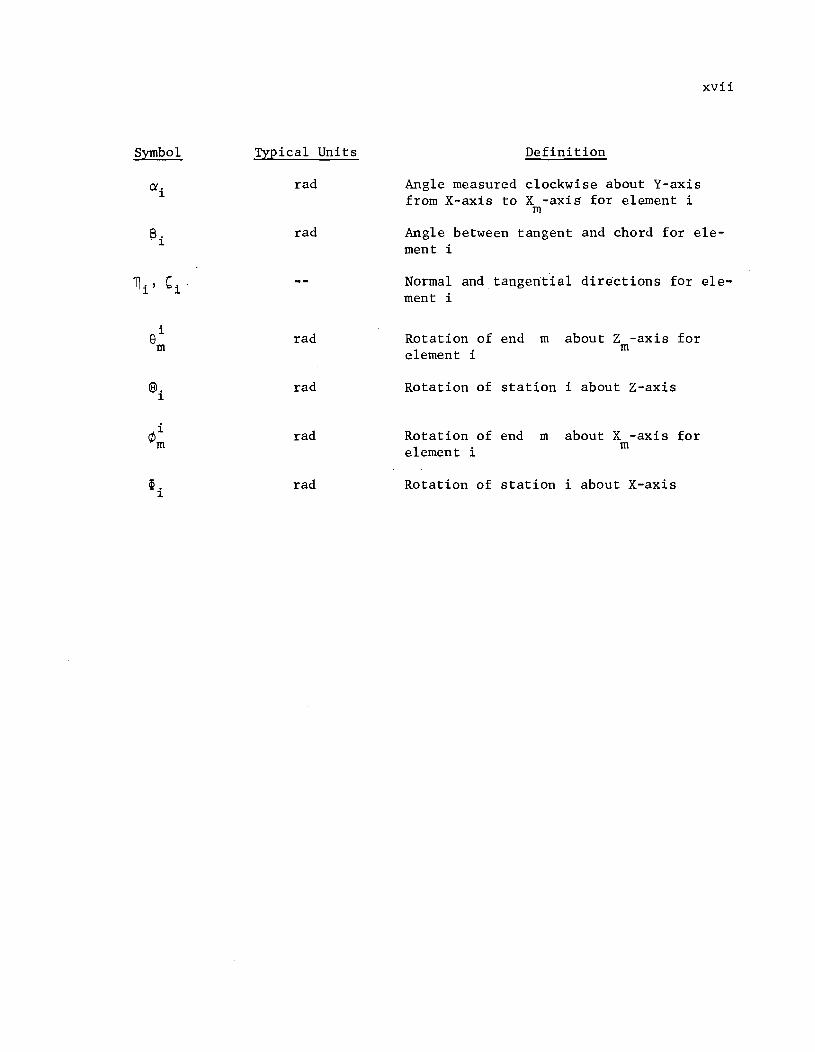
Symbol Typical Units
rad
rad
rad
@. rad 1
rad
~ . rad 1
Definition
Angle measured clockwise about Y-axis from X-axis to X -axis for element i
m
xvii
Angle between tangent and chord for element i
Normal and tangential directions for element i
Rotation of end m element i
about Z -axis for m
Rotation of station i about Z-axis
Rotation of end m element i
about X -axis for m
Rotation of station i about X-axis

CHAPTER 1. INTRODUCTION
Purpose
The construction of modern highway systems has led to ever increasing
use of continuously curved or polygonally curved girders and beams. Safe and
economical design of these structural elements requires a general procedure
for determining the displacements and internal forces induced by live and dead
loading. Although the analysis of curved beams has been the subject of many
studies, no totally general analytical procedure has yet been devised. A
variety of methods have been proposed; however, these methods are limited to
special classes of problems (Refs 2, 10, and 11) or lead to highly complex
arithmetic expressions which are of practical utility only when a digital
computer is used to perform the operations (Ref 9).
Development of the digital computer and finite-or discrete-element methods
have permitted the formulation of nearly completely general analytical proce
dures for many structural problems (Ref 7).
The purpose of this report is to present a finite-element method of
analysis for plane curved girders with all loads applied normal to the plane
of the member.
Preliminary Considerations
The basic concept of finite-element or discrete-element analysis is the
formulation of a model which maintains a high degree of geometric and behav
ioral similarity with the real structure, but which can be readily analyzed.
Models of structures curved in space have been proposed previously (Refs 1
and 8). These models replace the continuously curved member with a number of
straight segments which are chords of the curve. Obviously, the greater the
number of segments, the higher the degree of geometric similarity.
When the curved member lies in a single plane and is loaded normal to
that plane, the polygonally curved model becomes a special case of a grid type
structure (Ref 5). This type of structure can be analyzed by conventional
1

2
matrix methods of analysis and, as demonstrated later in this report by
example problems, the model responds to externally applied loads in the same
fashion as the continuously curved member. In addition, the finite-element
analysis procedure can be utilized to solve those problems which are not
susceptible to solution in closed form.

CHAPTER 2. METHOD OF ANALYSIS
Assumptions
A plane curved girder and a finite-element model of the girder are shown
in Fig 1. As stated in the preceding section, the finite-element model is a
special case of a plane grid and conventional matrix analysis techniques will
be used to determine the displacements and internal forces in the model. In
the succeeding derivations, it is assumed that all loads and restraints are
applied only at the intersections of the chord elements. These intersections
are referred to as the joints or stations of the girder. Stations are assigned
sequential identification numbers starting from one end of the structure. Each
element is identified by the larger of its two end station numbers.
The usual assumptions of frame analysis are maintained (Ref 4). Pri
marily, these assumptions are that the structure is linearly elastic and that
all displacements are small compared to other dimensions of the structure.
Development of Equations
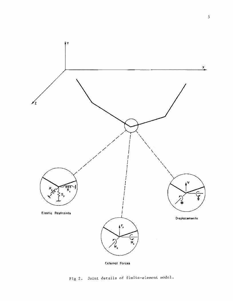
Details of the finite-element model are shown in Fig 2. Since this is a
grid structure, each joint in the model may be subjected to three external
forces or elastic restraints and may undergo three displacement components.
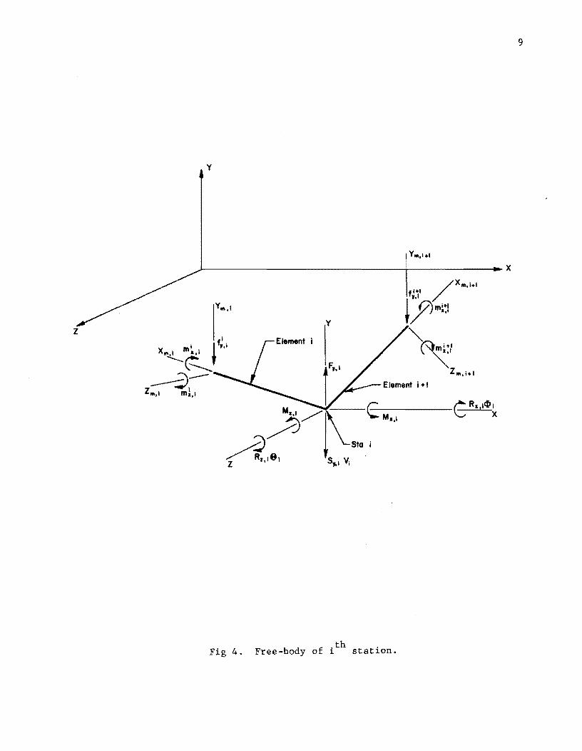
A free body of the ith element of the model appears in Fig 3. There
are three internal forces as shown in Fig 3(a) and three displacement com
ponents as shown in Fig 3(b) at each end of the element. The member end
forces and end displacements (Fig 3) are related to an auxiliary, or member,
coordinate system. The X -axis is defined by the centroidal axis of the pris-m
matic element. The Y - and 2 -axes are the principal axes of the cross-section. m m
Since the member lies in the X-2 plane, it is assumed that the Y -axis and m the global Y-axis, Figs 2 and 3, are parallel, and that the X -2 and global
m m X-2 planes coincide. Although these assumptions limit the orientation of the
principal axes of the cross-section of the element, it is not felt that this
is a serious limitation (Refs 4 and 8).
3

4
y
y
z
r
(a) Continuous curved girder.
(b) Finite-element model.
x .,.
Rotation Restraints
Fig 1. Curved girder and finite-element model.
x ..
z
y
/ /
/ /
/
Elastic Restraints
/ /
/ /
/ I I I I I I 1 1 I I I I I 1 I I
E)(ternal Forces
Fig 2. Joint details of finite-element model.
5
x
Displacements

6
v
v".
x
(a) Element end forces.
v
x
x.
(b) Element end displacements.
Fig 3. Free-body of ith finite element.

7
The element end forces are related to the element end displacements by
Ref 4.
i GJ 0 0
-GJ 0 0 i
m . 1 L L ciJi - l X,1-
fi l2EI -12EI 6EI i
0 Z
0 Z Z
y,i-l L3 L3 L2 vi - l
i 6E -6EI 2EI i
0 0 Z Z
m z,i-l L L2 e. 1 L 1-
= (1)
i -GJ 0 0
GJ 0 0 ¢~ m x,i L L 1
fi -12EI -6EI l2EI -6EI i
0 Z Z 0 Z Z
L3 L2 L3 L2 v.
y,i 1
i 6EI 2EI -6EI 4EI ei
0 Z Z 0
Z Z m
L2 L2 z,i L L i
Where the forces i fi and the displacements
i i m . 1 , , etc. ciJ. 1 v. 1 X,1- y,i-l 1- 1-
etc. are readily identified in Fig 3, and
GJ :::; torsional rigidity* of element i,
L :::; length of element i,
EI = bending rigidity of element i about Z -axis. z m
The matrix equation (Eq 1) may be expressed conveniently in the form
-i ::i ::i -i f. 1 S. 1 . 1 S. 1 . u. 1 1- 1- ,1- 1- ,1 1-
(2)
? ::i ? -i S .. 1 u. 1 1,1- 1,i 1
* See Appendix 1 for discussion of torsional rigidity.
,

8
where
-i f m
? m,n
-i u
m
=
=
=
(3 X 1) matrix of end forces at station m in element i,
(3 X 3) matrix of stiffness coefficients relating element end forces at station m to unit displacements at station n for element i, and
(3 X 1) n~trix of displacements of end m in element i.
Equation 2 is expanded to
"7i f. 1 1-
-i f.
1
=
=
~ -i ~ -i S. 1 . 1u . 1 + s. 1 .u. 1- ,1- 1- 1-,1 1
~ -i -=i-i S . . 1u . 1 + s. . u . 1,1- 1- 1,1 1
(3)
(4)
A free-body of the ith station of the finite element model is shown in
Fig 4. The conditions of equilibrium of the station are expressed by
where
M x, i
F y, i
M z,i
Q' n
-
+
-
-
=
.~ . i sin
i i+1 R - cos Q'.m x, i + Q'.m . - cos Q"+lm . x,1 1 1 1 Z,1 1 X,1
sin i+1
0 Q', 1m . = 1+ Z,1
S , V. fi fi+: = 0 y,1 1 y, i y,1
sin i i
sin i+1
R ,9. - Q'.m . - cos Q'.m . - Q"+lm . z,1 1 1 x,1 1 z,1 1 x,1
i+1 0 cos Q"+lm . = 1 z,1
angle measured clockwise about Y-axis from X-axis to X -m
axis for element n, Fig 3.
(5)
(6)
(7)
9
y
z
EM .. "
Fig 4. Free-body of ith station.

10
These equations may be arranged in matrix form as
M R 0 0 t. x,i x,i 1
F y,i 0 S y,i
0 V. 1
M z,i 0 0 R z,i <8l. 1
0 -sin i
cos O!i O!. m 1 X,i
0 1 0 fi y, i
sin O!. 0 i cos O!. m z,i 1 1
cos O!i+1 0 -sin O!i+1 i+11 m . X,1
0 1 0 fi+~ y,1 = 0 (8)
sin 0 i+1
O!i+1 cos O!i+1 m z,i
Introducing
cos O! n 0 -sin O!n
T = 0 1 0 (9) O!,n
sin O! 0 cos O!n n
M x,i
F. = F (10) 1 y,i
M z,i

R x, i 0 0
R. = 0 S 0 1. y, i
0 0 R z,i
and
~. 1.
U. = V. 1. 1.
e. 1.
Equation 8 may be expressed in matrix notation as
F. 1.
R.U. 1. 1.
~ T . f. a,1. 1.
- -i+l T '+If. == 0 a,1. 1.
Substitution of Eqs 3 and 4 in Eq 13 yields
11
(11)
(12 )
(l3)
F. - R. U. - T . S~ . l~~ 1 - T .? ~ - T . l?+~~+l 1. 1. 1. a,1. 1.,1.- 1.- a,1. 1.,1. 1. a,1.+ 1.,1. 1.
_ T ?+l -i+l a, i+l i, i+l u i +l o
Element end displacements lJi i '
to the station displacements
tions (Ref 4)
-i u.
1. =
= -* -TI'\I • U. 1
... ,1. 1.-
-* -T .U. a,1. 1.
U. 1 ' 1.-
-i+l u.
1.
(14)
(Fig 3b) are related
(Fig 2) by the transforma-

12
-i+1 -* u. = T '+lU, 1 Q',1 1
-:i+1 -* Ui +1 = TQ', i+1 Ui +1 (15)
where
T = Q',n transpose (Ref 5) of T Q',n
Combination of Eqs 14 and 15 leads to the governing equation
~ -* i ->', - -::1+1-* (T . S. . 1T . ) U. 1 + (T . S. . T . + T . 1 S. . T . 1 Q',1 1,1- Q',1 1- Q',1 1,1 Q',1 Q',1+ 1,1 Q',1+
- -:i+1-* + R.)U. + (T '+l S, '+IT '+l)U'+l = F. 1 1 Q',1 1,1 Q',1 1 1 (16)
Equation 16 expresses the load-deflection relationship which must be satis
fied at every station in the finite-element model.
solution of Simultaneous Equations
where
and
Equation 16 may be more compactly expressed as
d. is 1
= o
b. , and c. 1 1
are (3 X 3) matrices of stiffness coefficients
a (3 X 1) vector of external loads.
(17)
Evaluation of this equation at every station in the finite-element model
leads to a set of simultaneous, linear, matrix equations in the unknown dis
placements of the stations. An efficient procedure for solution of these
equations has been discussed by Endres and Matlock (Ref 3). Only an outline
of the procedure is given here.
At each interior station i, the unknown displacement vectors
Ui+
1 satisfy the equation
U. and 1

13
U. ::: A. + BiUi+l 1 1 (18)
if
-(a.B. 1 - -1 -- + d.) A. = + b.) (a.A. 1
1 1 1- 1 1 1- 1 (19)
and
-(~.B. 1 - -1
B. = + b.) c. 1 1 1- 1 1
(20)
where the superscript -1 indicates the inverse of the matrix (Ref 5). Since
evaluation of Eq 17 at end station 0 results in ao = 0 , values of Ai and
may be determined sequentially for each station beginning at station 0 B. 1
and proceeding to the final station n.
to zero values for both c and B n n
At station n evaluation of Eq 17
Hence, Eq 18 yields U ::: A n n
is obtained. A can be evaluated from known data, a solution for U n n
values for displacement vectors may be obtained by back substitution in
Support Reactions and Internal Forces
where
Support reactions are obtained from the equation
R.U. 1 1
leads
Since
Other
Eq 18.
(21)
= (3 X 1) matrix of forces in the three support springs at station i related to the global coordinate system.
Element end forces, ~ 1 and ~ , may be determined from known station 1- 1
displacements by application of Eqs 15, 3, and 4, respectively. As previously
stated, the forces obtained from these equations are related to the member
coordinate system for the straight chord element. For design purposes, it is
desirable that the internal forces be known in relation to a tangent and nor
mal to the curved member. The element and tangential coordinate systems for

14
/ Original Curved Girder
Sta. i-I
Fig 5. Normal and tangential coordinate systems for element i.

15
the ith element are shown in Fig 5. The element end forces may be expressed
in relation to the normal and tangential coordinates by the transformation
where
--:i fTj, i-I
--:i fTj . ,1.
? Tj,m
T 13 ,m
-* T
13 ,m
=
=
=
=
= --"Ir --:i TQ • f. 1
,-,,1. 1.-
-* -i TQ .f.
,-,,1. 1. (22)
(3 X 1) matrix of end forces in element i in normal and tangential directions at station m,
(3 X 3) transformation matrix of the form of TTj of Eq 9 except evaluated for angle 13m Fig 5, ,
transpose of T 13 ,m
.

!!!!!!!!!!!!!!!!!!!"#$%!&'()!*)&+',)%!'-!$-.)-.$/-'++0!1+'-2!&'()!$-!.#)!/*$($-'+3!
44!5"6!7$1*'*0!8$($.$9'.$/-!")':!

CHAPTER 3. THE COMPUTER PROGRAM
FORTRAN Program
The procedures described in the preceding chapter have been programmed
for solution on a digital computer. The program is written in FORTRAN IV for
the Control Data Corporation 6600 Computer. With minor changes, the program
will be operable on other computer systems. However, no solution should be
attempted on machines operating with less than twelve significant decimal
figures in arithmetic operations. A summary flow diagram for the FORTRAN pro
gram is given in Fig 6. Detailed flow charts and a listing of the program are
included in Appendices 3 and 4.
The input data, insofar as is possible, has the same form as conventional
beam-column data (Ref 7). The form of the input data is shown in the Guide
for Data Input in Appendix 2. The following paragraphs give the assumptions
on which the input data are based.
Description of Girder
The global coordinate system is selected arbitrarily and the geometry of
the girder is referenced to the global system. The plane of the curved girder
must lie in the global X-Z plane and one principal axis of the girder cross
section must be parallel to the global Y-axis.
In order that as much data as possible may be generated automatically,
the girder is assumed to be composed of combinations of straight and circu
larly curved segments. Required data for each station on the girder consist
of the station number, beginning with station zero, and the global X and Z
coordinates of the station. Station numbers and coordinates for a segment of
the girder are generated automatically at equal intervals along a straight
line between indicated end points if the segment is not designated as a curve.
For a curved section, the global X-Z coordinates of the center of the cir
cular arc must be supplied in addition to the station numbers and coordinates
for the terminal stations of the section. Intermediate stations are generated
17

18
I START I
~ I READ input datal
I IGenerate station numbers I
and coordinates
I IDistribute data to stationsl
I ISolve for station displacementsl
I I PRINT station displacementsl
I (--- DO for each element)
I Isolve for element end in element coordinate
forces I system
I IElement part of No curved section?
I Yes
Convert element end forces to normal and tangential components
~ IPRINT element end forceSl
'--------1 I RETURN for new problem I
)
Fig 6. Summary flow chart.

at equal arc lengths between the terminals. The included angle for any arc o length must not exceed 180 .
The above interpolation procedure permits the use of unequal increment
lengths.
Girder Supports and Restraints
19
The girder must be restrained to prevent all possible rigid body displace
ments. Three elastic restraints may be applied to each station. These include
restraint of rotation of the joint about the global X-axis, restraint of trans
lation of the joint in the global Y-direction and restraint of rotation of the
joint about the global Z-axis. Unyielding supports may be simulated by speci
fying a large value of elastic restraint. Elastic restraints may be applied
to individual stations or may be distributed over a range of stations in the
same manner as the spring supports of ordinary beam-column data (Ref 7) pro
vided that the increment length is constant within the distribution range.
Element Stiffnesses and Coordinate System
Each element of the girder between adjacent stations is assumed to be a
straight, prismatic elastic grid member. Torsional and flexural stiffnesses
are supplied re~ated to a coordinate system defined separately for each ele
ment. In this special coordinate system, the X -axis is defined by the cen-m
troidal axis of the prismatic element and the Z -axis is oriented such that m
the X -Z plane and the global X-Z plane coincide. In addition, the positive m m Y -direction is parallel to the global Y-axis. As stated previously, the
m X , Y ,and Z-directions are assumed to be the principal axes of the m m m
element cross-section (Fig 3).
Stiffness values may be supplied for individual elements or may be auto
matically distributed over a section of the girder by linear interpolation
between specified end stations. This automatic generation option must be
applied only over those sections of the girder having a constant element
length, otherwise erroneous stiffness values may result.
Applied Loads and Moments
Loads and moments are applied to stations related to the global coordinate
system. Forces are assumed to be positive when the vector is in the same

20
direction as the positive Y-axis. Forces in the global X- and Z-directions
are not permitted. A moment about the X- or Z-axis is positive when the
vector, given by the right-hand screw rule, points in the positive X- or Z
direction. Moments about the Y-axis are not permitted.
Input Data
Formats and additional explanatory information for the input data are
given in Appendix 2. The data for each problem are arranged in tabular form
as outlined below. Two alphanumeric cards are required at the beginning of
each data deck. These are followed by
(1) Problem Identification card with alphanumeric description of the problem. The program terminates if the problem identification is blank.
(2) Table 1. Program Control Data - 1 card. Each of Tables 2, 3, 4, and 5 may be retained from the preceding problem by inserting the code ''KEEP'' at the appropriate location in Table 1. The number of cards added to each table is supplied on this card.
(3) Table 2. Station Coordinates. The station' number and global coordinates of each station are supplied. The number of cards added to this table is given in Table 1. When stations are to be generated on a circular arc, the card containing the station number and coordinates of the beginning station must also include the jdentifier "CURVE" and the global coordinates of the center of the arc. Addition of information to Table 2 held from the preceding problem is not permitted.
(4) Table 3. Elastic Restraints. The number of cards in this table is specified in Table 1.
(5) Table 4. Element Stiffnesses. The number of cards is specified in Table 1. Care must be taken to insure that every element has been assigned a nonzero value of flexural and torsional stiffness. Otherwise the program will terminate.
(6) Table 5. Applied Loads and Moments. The number of cards is specified in Table 1.
As many problems may be run in succession as desired. The data coding
sheets for the example problems of Chapter 4 are reproduced in Appendix 5.
OUtput Data
All input data are echo printed as read. Output of the computed data is
arranged in Table 6 as follows

21
(1) Station Displacements in Global Coordinate Directions. The identification number, global coordinates, rotations about the global X- and Z-axes and deflection in the global Y-direction are printed for each station. The sign convention for the displacements is given in Fig 2.
(2) Element End Forces in Normal and Tangential Directions. The member end forces are initially computed related to the member coordinate system of the element (Fig 3). If the element is part of a curved section, the end forces are transformed to normal and tangential directions as shown in Fig 5.
Output data for the example problems of Chapter 4 are given in Appendix 6.

!!!!!!!!!!!!!!!!!!!"#$%!&'()!*)&+',)%!'-!$-.)-.$/-'++0!1+'-2!&'()!$-!.#)!/*$($-'+3!
44!5"6!7$1*'*0!8$($.$9'.$/-!")':!

CHAPTER 4. EXAMPLE SOLUTIONS
A variety of problems have been solved to verify the analytical procedure
and the computer program described in the preceding chapters. The results
obtained by the program are compared with closed form solutions, other numeri
cal procedures and with experimental data. The input data and the computer
output are presented in Appendices 5 and 6, respectively.
Rectangular Bracket
The rectangular bracket shown in Fig 7 is composed of hypothetical
straight, circular cross-section members having equal bending and torsion
stiffnesses. The behavior of members of this type is not affected by warping
of the cross-section (see Appendix 1). Hence, the method of analysis des
cribed in Chapter 2 does not introduce any further approximation and the re
sults are identical with those obtained by application of any method of
indeterminate structural analysis (see, for instance, Ref 6).
Output data from the computer analysis for this structure are presented
as Problem CGll in Appendix 6. Although 36 stations were used to give a more
detailed determination of the deflections and internal forces, an exact solu
tion for forces and deflections at the stations could have been obtained using
as few as three elements and four stations. In the latter case, the four
stations necessary are those labeled 0, 16, 20, and 36 in Fig 7.
Semicircular Bow Girder
The pipe girder shown in Fig 8a is subjected to a uniformly distributed
lateral load. As in the previous example no warping effects are present and
the problem is readily solved by conventional methods of indeterminate struc
tural analysis (Ref 6). The solutions obtained by the finite-element method
and by a closed form method are tabulated in Fig 8b. It is seen that excel
lent agreement is obtained for as few as ten increments in the model. Agree
ment is further improved when twenty increments are used.
23

24
10'
z
y
r---------------~~~~r_------x
All members
E Iz ; GJ
Fig 7. Rectangular bracket.

b
Uniform Vertical Load: 120 Ib/ft
10~ inch 0.0. x 0.279 inch W.T.
25
---x
z
(a) Plan view, semicircular bow girder.
Point a Point b
Least PCGR Least PCGR
Work 10 Incr 20 Incr Work 10 Incr 20 Incr
Bending Moment (Ib-in) 1.440 x 10' 1.428 xlO' 1.437 x 10' -3.934 X 10⁴
-3.954 x 10· -3.939xI04
Twisting Moment (lb.-in) -4.285 xl04 -4.385 x 10· -4.310xI0· 0 0 0
Vertical Reaction (Ib) 1.885 x 10' 1.885 X 10' 1.885 X 10' - - -
Vertical Deflection (i n) 0 0 0 - 0.2176 - 0.2165 -0.2173
(b) Comparison of results.
Fig 8. Comparison of results with closed-form solution.

26
Output data for this problem are included in Appendix 6 as Problems CG12
and CG13.
Circular Arc I-Beam
The experimental and analytical r.esul ts of a study of the circularly
curved I-section, shown schematically in Fig 9, are reported in Ref 10. These
data, together with the solution obtained with the method reported herein are
compared in Figs 10 and 11 for two loading conditions. It is pointed out in
Ref 9 that although the beam was encased in concrete at each end, the ends of
the beam were not completely restrained as was assumed in the analysis (Fig 9).
This is evidenced by the nonzero vertical deflection indicated at station zero
in Fig lOb. The deflections obtained by the finite-element analysis agree
well with those obtained experimentally as reported in Ref 10.
Since the ends of the beam are built in, the end cross-sections are not
free to warp. This increased stiffness results in a reduction of the angle of
twist in the vicinity of the restraint. This effect is evident in the com
parisons presented in Fig 11. The effect of warping restraint is not consid
ered in the finite-element analysis; hence, the twist angles indicated are
higher than those obtained experimentally. However, excellent agreement is
obtained in the center portion of the beam where the effect of the warping
restraint is reduced.
Straight Beam Solution
Since an ordinary straight beam is a special case of the grid analysis
method described in this report, the program may be used to solve a wide vari
ety of beam problems. One particular advantage is the ability to use varying
increment lengths in describing the beam. To illustrate the use of the pro
gram in this respect the beam shown in Fig 12 is solved and the results are
compared with those reported in Ref 7. It is seen that excellent agreement
is obtained with the previously reported procedure.
It should be noted, however, that the beam is solved as a special case
of a grid structure. As such it is expected by the program that the structure
will be subjected to the effects o~ moments about the X-axis even though none
are imposed by the loading system. As a consequence nominal values of torsional
rigidity (GJ) and restraint against rigid body rotation about the X-axis (RX)

27
324"
L------t~-=~~~~----~-----------x @)
0.54 Rod.
z
Fig 9. Circular arc I-beam (after Ref 10).

28
.S; ~
IS :;:: j .... ! "8 :;:: .. ~
.5
.~ -~ i 0
'8 :;:: ... ~
Station
00 2 4 6 8 10 12 14 16 18 20 ....
-0.\ , , ,/
// // -0.2 ,/
,/
/
/ -0.3 /
/
Calculated by PCGR
-0.4 ---- Calculated bj Ref. 10
- --- Experimental, Ref. 10
-0.5
(a) Vertical deflection due to I-kip vertical load at station 10.
-0.1
-0.2
-0.3
-0.4
-0.5
8 Station
10
------
12 14 20
Calculated by PCGR
Calculated by Ref. 10
Experimental, Ref. 10
(b) Vertical deflection due to I-kip vertical load at station 6.
Fig 10. Comparison of calculated and experimental deflections for circular I-beam (after Ref 10).

0.02
0.01
III 0::::
0.0 C :g ... Q)
"0 -0.01 0::::
oct .. III
~ -0.02
-0.03
-0.04
0.02
0.01
III 0:::: c
0.0 ~ c ... Q)
"0 -0.01 0::::
oct .. WI
~
-0.03
-0.04
Station
2 8 10
o~
12
I
I
Calculated by PCGR
- - - - Calculated by Ref. 10
o Experimental, Ref. 10
(a) Twist angle due to I-kip vertical load at station 10.
-----12 .y- 16 18 ~~
Calculated by PCGR
---- Calculated by Ref. 10
0 Experimental, Ref. 10
(b) Twist angle due to I-kip vertical load at station 6.
Fig 11. Comparison of calculated and experimental twist angles for circular arc I-beam (after Ref 2).
29

30
10ft
Sta 0
49!50 ,
10ft 10ft 10ft
10 20
(a) Continuous straight beam (after Ref 7).
I Station Deflection (in) Bending Moment(lb-in)
Ref 1 PCGR Ref 1 PCGR
0 5.140 x 10⁻¹ 5.775 x Kr l -5.035 x 10⁻⁴ 0
10 4.713 x10- 2 4.101 x 10⁻² 3.261 X 10⁵ 3.261 X 10 5
20 2.141 X 10⁻¹ 2.143xI0- 1 1.124 X 10" 1.121 xl0 6
30 1.298 1.291 -9.190 X 10⁵ -9.195 x 10⁵
35 1.041 1.045 -3.335 x 10⁵ -3.341xI05
40 5.315 X 10⁻¹ 5.328 X 10⁻¹ -1.263 X 10⁻⁴ 0
(b) Comparison of results.
Fig 12. Comparison of results with discrete-element analysis of continuous beam.
40

must both be supplied. In the case at hand, unit values of these data were
utilized (see Appendices Sand 6).
Curved Highway Girder
31
A curved girder which is similar to those used in curved highway bridge
structures is shown in Fig 13. In addition to the fixed supports shown in the
figure, it is assumed that diaphragms, parallel to the global X-axis, frame
into the girder at every tenth station beginning at station 3 and ending at
station 153. The numerical values of restraint (see Appendices 5 and 6) are
for a pair of lSU33.9 sections at each diaphragm station.
Although the wide flange cross-section is susceptible to the effects of
warping of the cross-section it is unlikely that any significant amount of
warping will be provided by the supports. Hence, the analytical procedure
described in this report may be utilized ~ith sufficient accuracy. Restraint
against twisting of the girder, provided by the deck slab will tend to make
the results of the analysis err on the side of safety.

32
..... --------- Radius = 475 ---~---------........ I r---------------------------,-__ --------__________ -T0~~--~X
6° 16.3'
26
z
(a) Plan.
Station
1 t-t-r~f-r-I ~~ I
10 in, x II, in. t-<, I rOin.xlin.t-{ I 1O\Iz In. x I in. It. '""""""\. lOinx~in. t -1
Arc Dist!lllCt 52 ft 12ft 75 ft . 26 ft. 55 ft . 31 ft. ...24 ft. 40 ft.
Beam -160 ..J6 'IF 135,. Ixp.! 36 'IF 135 36 'IF
~ixed * . . * see Text for Additional Diaphragm Support •
(b) Elevation.
Fig 13. Typical curved highway girder.

CHAPTER 5. CONCLUSIONS AND RECOMMENDATIONS
Conclusions
A method for analysis of plane curved girders has been presented. The
method consists of replacing the curved member with an assemblage of straight
structural elements which are chords of the original curve. Each of the chord
elements is then analyzed as a grid member using conventional matrix methods
of structural analysis. The resulting equations are solved using a direct
solution on the digital computer. The program, PCGR2, has been used to solve
a number of problems to verify the method of analysis and the accuracy of the
computer program. As demonstrated by the example problems, the method is
applicable to a wide variety of practical problems.
Recommendations
Several significant areas requiring additional research have been en
countered during the course of this study.
Of primary importance is the determination of the effective torsional
rigidity of open cross-sections when warping effects are present. The use
of the conventional to~sional stiffness parameter yields excellent results at
points which are located at some distance from the point of restraint. How
ever, in the vicinity of the restraint, warping of the cross-sections creates
additional torsional rigidity which is not accounted for by the conventional
term.
Utilization of the variable increment length capability of the computer
program described herein may require a large amount of manual computation to
obtain the data required as input, particularly in the case of distributed
data. The distribution procedure should be modified to accept data which are
distributed with respect to distance along the member as well as with respect
to stations as is now the case. A further modification of the program should
be to permit elastic restraints at the stations at orientations other than in
the global coordinate directions.
33

!!!!!!!!!!!!!!!!!!!"#$%!&'()!*)&+',)%!'-!$-.)-.$/-'++0!1+'-2!&'()!$-!.#)!/*$($-'+3!
44!5"6!7$1*'*0!8$($.$9'.$/-!")':!

REFERENCES
1. Baron, Frank, 'Matrix Analysis of Structures Curved in Space," Proceedings, Vol 87, No. ST3, American Society of Civil Engineers, March 1961.
2. Brookhart, G. C., "Circular-Arc I-Type Girders," Proceedings, Vo193, No. ST6, American Society of Civil Engineers, December 1967.
3. Endres, Frank L., and Hudson Matlock, "An Algebraic Equation Solution Process Formulated in Anticipation of Banded Linear Equations," Research Report No. 56-19, Center for Highway Research, The University of Texas at Austin, January 1971.
4. Gere, J. M., and W. Weaver, Jr., Analysis of Framed Str~~tures, D. Van Nostrand Co., Inc., Princeton, New Jersey, 1965.
5. Gere, J. M., and W. Weaver, Jr., Matrix Algebra for Engineers, D. Van Nostrand Co., Inc., Princeton, New Jersey, 1965.
6. Kinney, J. S., Indeterminate Structural Analysis, Addison-Wesley Publishing Co., Inc., Reading, Massachusetts, 1957.
7. Matlock, Hudson, and T. A. Haliburton, "A Finite-Element Method of Solution for Linearly Elastic Beam-Co1unms," Research Report No. 56-1, Center for Highway Research, The University of Texas at Austin, September 1966.
8. Michalos, James, 'Matrix Formulation of the Force Method for a Structure Curved in Space," Publications, Vol 26, International Association for Bridge and Structural Engineering, Zurich, 1966.
9. Soto, M. H., "Analysis of Suspended Curved Girder," Proceedings, Vol 92, No. ST1, American Society of Civil Engineers, February 1966.
10. Spates, K. R., and C. P. Heins, Jr., "The Analysis of Single Curved Girders with Various Loadings and Boundary Conditions," Progress Report for Maryland State Roads Commission and U.S. Bureau of Public Roads, Civil Engineering Department, University of Maryland at College Park, June 1968.
11. Thibodeaux, M. H., ''Numerical Analysis of Normally Loaded Plane Frames," thesis presented to the University of Illinois, Urbana, in partial fulfillment of the requirements for the degree of Doctor of Philosophy, 1958.
12. Timoshenko, S., Strength of Materials, Vol I and II, D. Van Nostrand Co., Inc., Princeton, New Jersey, Third Edition, 1956.
35

!!!!!!!!!!!!!!!!!!!"#$%!&'()!*)&+',)%!'-!$-.)-.$/-'++0!1+'-2!&'()!$-!.#)!/*$($-'+3!
44!5"6!7$1*'*0!8$($.$9'.$/-!")':!

APPENDIX 1
TORSIONAL RIGIDITIES

!!!!!!!!!!!!!!!!!!!"#$%!&'()!*)&+',)%!'-!$-.)-.$/-'++0!1+'-2!&'()!$-!.#)!/*$($-'+3!
44!5"6!7$1*'*0!8$($.$9'.$/-!")':!

APPENDIX 1. TORSIONAL RIGIDITIES
In the derivations of Chapter 2, the relationship between the twisting
moments and angular displacements at the ends of the prismatic element is
and
i mx i-I ,
i m . x,~
=
=
i ¢. ) ~
GJ i i L (-¢. 1 + ¢.)
~- ~
(A1.l)
(A1.2)
This relationship is referred to as the St. Venant theory of torsion and is
well documented in any standard reference on strength of materials (see, for
instance, Ref 12). The factor GJ in the equations is the torsional rigidity
of the element, where G is the shear modulus of the material and the value
of J depends on the geometry of the cross-section. For example, for a solid
circular cross-section, J is the polar moment of inertia of the circle and
4 J = TTr
4 (A1.3)
where r is the radius of circle. Values of J for other solid or closed
cross-sections are tabulated in Ref 12.
When the cross-section is composed of thin rectangular elements, such as
I or H sections, and the cross-section is free to warp out of its original
plane, the factor J may be obtained from
n
J = tI i=l
3 b.t. ~ ~
39
(A1.4)

40
where
n = number of plates in cross-section,
b. = width of .th plate, and l.
l.
t. = thickness of .th plate. l. l.
This equation was utilized for determining the torsional rigidities for
b1em CG41 and is applicable since nu warping restraint is imposed at any
cross-section.
pro-
In the structure analyzed in problems CG31 and CG32, the ends of the I
sections were encased in concrete and warping of the cross-section was inhi
bited. In this case the torque-twist relations expressed in Eqs A1.1 and A1.2
are not directly applicable and a more complex relationship between twisting
moment and twist angle should be used (see Ref 12, Vol II, pp 255-265). How
ever, to apply this more complex relationship, an additional unknown must be
introduced at every station; that is, the rotation of the member about the
global Y-axis. This would increase the amount of computational effort by
twenty-five percent. In view of the excellent comparison with experimental
results indicated in Figs 10 and 11 at points remote from the applied warping
restraints, the additional refinement appears to be unwarranted. A more
expedient approach appears to be to increase the conventional torsional rigi
dity in the vicinity of a warping restraint. The amount of increase and the
region of the member to which the increase should be applied must be the sub
jects of further study.

APPENDIX 2
INPUT FORMS

!!!!!!!!!!!!!!!!!!!"#$%!&'()!*)&+',)%!'-!$-.)-.$/-'++0!1+'-2!&'()!$-!.#)!/*$($-'+3!
44!5"6!7$1*'*0!8$($.$9'.$/-!")':!

GUIDE FOR DATA INPUT FOR PCGR 2
with supplementary notes
extracted from
FINITE-ELEMENT METHOD OF ANALYSIS FOR PLANE CURVED GIRDERS
by
William P. Dawkins
June 1971

This page replaces an intentionally blank page in the original --- CTR Library Digitization Team

PCGR 2 GUIDE FOR DATA IN~UT Card Forms
IDENTIFICATION OF RUN (2 alphanumeric cards per run)
IDENTIFICATION OF PROBLEM (one card each problem; program stops if PROB NAtlli blank)
PROB NAME I I Description of problem (alphanumeric)
4 II
TABLE 1. PROGRAM CONTROL DATA (one card each problem)
ENTER "KEEP" TO HOLD PRIOR NUM CARDS ADDED FOR TABLE 2 3 4 5 TABLE 2 3 4 5
I [ I I I I IS IS IS IS 6 9 II 14 16 19 21 24 31 40 45 50
TABLE 2. STATION COORDINATES (number of cards according to TABLE 1, none if preceding TABLE 2 is held.) Coordinates are generated at equal intervals for omitted stations.
GLOBAL COORDINATES
STA. x z IS ElO.3 ElO.3
6 10 16 25
ENTER "CURVE"
FOR CURVED MEMBER
56 60
COORDINATES OF CENTER OF CIRCLE IN GLOBAL X-Z
PLANE XC ZC
ElO.3 ElO.3 70
80
80
80
80

This page replaces an intentionally blank page in the original --- CTR Library Digitization Team

TABLE 3. ELASTIC RESTRAINTS (number of cards according to TABLE 1). Data added to storage as lumped quantities per station (or per increment length), linearly interpolated between values input at indicated end stations, with 1/2 values at each end station. Concentrated effects are established as full values at single stations by setting final station = initial station.*
ENTER "CONTD"
RESTRAINTS IF CONTU FROM TO TO NEXT
IN GLOBAL COORDINATE DIRECTIONS
STA STA CARD RX SY RZ
I IS IS ElO.3 RIO.3 ElO.3 6 10 15 20 30 40 50 60 70
TABLE 4. ELEMENT STIFFNESSES (number of cards according to Table 1). Element stiffnessesi~* are added to storage as lumped quantities for each increment, linearly interpolated between values input at indicated ena stations, with full values for all increments. ~vn nonzero values of stiffness must be supplied for each increment.** Stiffness data are interpreted as applying over a segment of the structure as indicated by the ''FROM'' - liTO" station specifications, therefore, the "TO" station must be greater than the "FROM" station.
ENTER "CONTD" BENDING IF CCNTD TORSION S T IFFNE S S "f<,'c,':
l'l,;OM TO TO NEXT STIFFNESS ABOUT Z STA STA CARD EIZ rn
GJ IS IS ElO.3 EIO.3
6 10 15 20 30 40
* See page 57 for separate explanation of sequencing procedure. ** See page 59 for separate explanation of sequencing procedure.
50 60
*** Element stiffnesses are supplied related to element coordinate systems.' (See page 55 for explanation.)
80

This page replaces an intentionally blank page in the original --- CTR Library Digitization Team

TABLE 5. APPLIED LOADS AND MOMEtITS (number of cards according to TABLE 1). Data added to storage as lumped quantities per station (or per increment length), linearly interpolated between values input at indicated end stations, with 1/2 values at each end station. Concentrated effects are established as full values at single stations by setting final station initial station.*
6
FROM STA
IS 10
TO STA
IS 15
ENTER "CONTD" IF CONTD TO NEXT
CARD
20
XM
E10.3
FORCES IN GLOBAL
COORDINATE DIRECTIONS
FY
E10.3 30 40
STOP CARD (one blank card at end of run)
~See page 57 for separate explanation of sequencing procedure.
ZM
E10.3 50 60 70 80
80

This page replaces an intentionally blank page in the original --- CTR Library Digitization Team

GENERAL PROGRAM NOTE S
The data cards must be stacked in proper order for the program to run.
Input in integer fields must be right justified in field.
A consistent set of units must be used for all input data - e.g., pounds and inches.
TABLE 1. PROGRAM CONTROL DATA
All ''KEEP'' blocks must be blank for the first problem of a run.
If Table 2 is held, no new information may be added to Table 2. If Table 2 is to be revised, it must be supplied with all data.
For each of Tables 3, 4, and 5 the data are accumulated in storage by adding to previously stored data. The number of cards input is, therefore, independent of the hold option.
TABLE 2. STATION COORDINATES
Stations are assumed to lie on straight lines or segments of circular curves. If columns 56-60 are blank, the segment is assumed to be a straight line. If "CURVE" is inserted in columns 56-60, the segment is assumed to be a circular arc. The values of XC and ZC are Global coordinates of the center of the circle in the Global X-Z plane. The first card of a sequence governs whether the segment is a straight line or a circle; therefore, columns 56-80 on .the last card in Table 2 are ignored.
A maximum of 50 cards is permitted in Table 2.
The maximum number of curves is 20.
The first card in Table 2 must contain the information for station zero.
The maximum number of stations in the member is 200.
TABLE 3. ELASTIC RESTRAINTS
Typical units: SY lb/in
RX, RZ in-lb/radian
Data are distributed to stations between indicated end stations according to the station-by-station interpolation procedure shown on page 57.

This page replaces an intentionally blank page in the original --- CTR Library Digitization Team

There is no restriction on the order of cards in Table 3 except that within a distribution sequence the stations must be in ascending order. The maximum number of cards in Table 3 is 50.
The station-to-station distance must be constant within the interpolation interval indicated by the FROMTO stations.
TABLE 4. ELEMENT STIFFNESSES
Typical units: GJ
lb-in2
EIZ
lb-in2
Data in this Table sho~ld not be entered (nor held from the preceding problem) which would yield nonzero values beyond the ends of the real structure.
Data in this Table are distributed according to the element-by-element interpolation procedure shown on page 59.
The station-to-station distance must be constant within the interpolation interval indicated by the FROMTO stations.
A maximum of 50 cards is permitted in Table 4.
TABLE 5. APPLIED LOADS AND MOMENTS
Typical units: FY lb
MX,MZ lb-in
Data in this Table are distributed according to the station-by-station interpolation procedure shown on page 57.
The station-to-station distance must be constant within the interpolation interval indicated by the FROMTO stations.
An applied load is positive if its vector has the same sense as the corresponding Global Axis.
An applied moment is positive if its vector, given by the right-hand screw rule, has the same sense as the Global X- or Z-Axis.

This page replaces an intentionally blank page in the original --- CTR Library Digitization Team

Element stiffnesses are related to a coordinate system defined separately for each element as foilows:
y
x
Joint i +1
x, Y,Z
x ,Y ,Z m m m
X m
Y Z m' m
Global coordinate system
Element coordinate system
Centroidal axis of pr ismatic element
Principal axes of element cross section
Element must be oriented such that
Y and Y axes are parallel and m
x -z and X-Z planes coincide. m m

This page replaces an intentionally blank page in the original --- CTR Library Digitization Team

Procedure for Station-by-Station Distribution
Individual-Card Input FROM TO CONTD R S STA STA ? etc.
x y
7-+7 3.0 • 5' -+1 ~ 2.0 i)
Case lao Data concentrated at one station - - - - -
Case lb. Data uniformly distributed - -
15-+20 '+.0 1.0 e J 0 --';"2 0 2.0 0
Multiple-Card Sequence
Case 2. First-of-sequence - - - - - - - 125 ~~~~~~====~~==~
Case 3. Interior-of-sequence - - - - - ~ 1 IcfNTOI 0.0 2.0 :---0 1 30 IC9>NTDI 4-.0 2.0 <9 ~I ==~~~~~~~~====* 136 I~NTDI 2.0 <9 I~o 1 1 2..0 ----Cas e 4. End- 0 f- sequence - - - - - - - - 1'--__ ...L......::........=----l ___ ...L-----.::=....::~_----L _____ ..L...
Resulting Distribution of Data
R x
Stotion No.: 0
S Y
Slalion No: 0
I I
5 10
5 10
15 20
15 20
-4-
-3-
-2-
-1-
25 30 35 40
-3-
-2-
-1-
I I
25 30 35 40

This page replaces an intentionally blank page in the original --- CTR Library Digitization Team

Procedure for element by element distribution
Individual-Card Input
Case lao Data for one element - - -
Case lb. Data uniformly distributed - - -
Multiple-Card Seguence
Case 2. First-of-sequence
FROM TO CONTD STA STA ?
- ~ 0--71
~ 1 ~15'
FROM TO CONTD STA STA ?
IC~NTDI
GJ or EIZ
"'".0 • 2.0 e
4.0
1.0 o
GJ or EIZ
J.O I~ Case 3.
-~--~~~~--~ Interior-of-sequence - - - - - - - - - - - - - - - - ~~_3~~~:~~~~~ __ ~~ ____ ~ End-of-sequence - - - - - - - - - - - - - - - - - - -Lc=== ____ (;=~:_~~O~~ ____ ~ __ ~~ ____ ~
:~: /0
4-.0
:<: 2.0 C(J)NTD
I I ,/ Case 4.
6
5
4-
3
2
1-
Element No. :
Station No. : 0 5
2.0
10 15 20 25 30

This page replaces an intentionally blank page in the original --- CTR Library Digitization Team

APPENDIX 3
FLOW DIAGRAMS

!!!!!!!!!!!!!!!!!!!"#$%!&'()!*)&+',)%!'-!$-.)-.$/-'++0!1+'-2!&'()!$-!.#)!/*$($-'+3!
44!5"6!7$1*'*0!8$($.$9'.$/-!")':!

PROGRAM PCGR2
READ problem name and identification
Problem name blank?
No
READ program control data
First problem of run?
Set up card counts for Tables 2, 3, 4, 5
READ and echo print Table 2-station coordinates
Generate missing station coordinates
READ and echo print Table 3-elastic restraints
Distribute Table 3 data to stations
CALL INTERP
READ and echo print Table 4-element stiffnesees
Yes
Yes
63
See separate flow diagram, pages 66, 67, and 68
See Ref 7 for details of interpolation procedure

64
Distribute Table 4 data to stations
CALL INTERP
All element stiffnesses positive?
Yes
READ and echo print Table 5-applied loads
Distribute Table 5 data to stations
Solve for station displacement by 3 wide recursion -inversion process
CALL SOLVER
PRINT number, coordinates and dis
·placements for each station
,-- - - DO for each element
I I I I I I I I I I I
Calculate element end forces in normal and tangential directions
ORCES
forces
\.._-------RETURN for new problem
No
See Ref 3 for details of recursion -inversion process. See flow diagram for Subroutine FSUB, pages 70 and 71

PROCEDURE FOR GENERATION OF MISSING STATION DATA I
I I - 1+1 I
READ Control Station' Data IN(I), XN(I), ZN(I), CURVEN(I), XCN (1), ZCN (I)
I I ... l?
No
Number of Elements in Segment
Yes
NEL == IN (I) - IN (1-1)
Is Segment Curved? CURVEN(I-l) ::: CURVE
No
Generate Missing Station Data Along Straight Line
Increments in X,Z Coords.
DX = (XN(I) - XN(I-l))/NEL DZ (ZN (I) - ZN (I-i)) /NEL
DO For Each Station ,-- On Line J == 1 to NEL I I I I I I
X,Z Coordinates of Station
x (J) Z(J)
X(J-l) + DX Z(J-l) + DZ
I Isegment Identifier I l ____ ::~J) 1-1
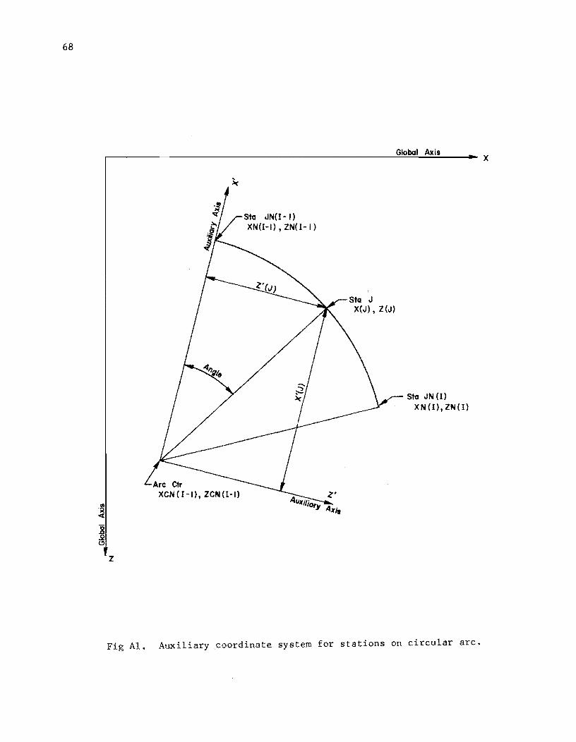
See Fig Al, page 68
X(2) = XN(I) Z(2) ::: ZN(I)
Yes
-
65

66
No
Echo Print Control Station Data and Segment Type Description
Last Card in Table? I > NCD2?
Yes
Number of Elements in Model
NB = IN(NCD2)
I Table 3 Input
Generate Missing Station Data Along Circular Arc
Arc Radius
RADIUS = ~[XN (I) - XCN 2 2
(I-1)J + [ZN(J) - ZCN(I-1)J
Chord Length of Arc
CHORD = ~[XN(I) - XN( I-1)J2+ [ZN(I) - ZN(I-1)J
2
Angle Enclosed by Arc ANGLE = 2 * ARSIN (0.5 * CHORD I RADIUS)
Angle Enclosed by Each Element DANGLE = ANGLE I NEL
Direction Cosines for Auxi liary Coord. System CX = CZ =
(XN(I-1) - XCN(I-1 (ZN(I-1) - ZCN(I-1
I
» / RADIUS » / RADIUS

I Do For Each Station on Arc
(-- J ., 1 to NEL
Angle from X Axis to Station m ANGLE = J * DANGLE
Station Coords. in Aux. System XPM = RADIUS * COS (ANGLE) ZPM = RADIUS * SIN (ANGLE)
Station Coords. in Global System X(J) = cx * XPM - CZ * ZPM + XCN(I-l) Z(J) = cz * XPM + ex * ZPM + ZCN(I-l)
Isegment Identifier I IDSEG(J) = 1-1
"--------.~
67
68
z
Stu IN(I-I) XN(I-I) , ZN(I - I )
Global Axis
Stu J X(J) , Z (J)
,-- Stu IN (I) . XN(l),ZN(I)
Fig AI. Auxiliary .coordinate system for stations on circular arc.
x

69
SUBROUTINE FORCES
9 Calculate Element Length and Direction Cosines of Element Coord. System With Respect to Global Coord. System
Set Up Coord. I Transformation Matrix
Ca lcula te :1 nt Stiffness Coefficients and Set Up Element Stiffness Matrix
Set Up Element End Displacement Matrix From Station Displs'l
Transform Element End Displs. to Element Coord. System
Is Element Part of No Curved Segment?
Yes
Calculate Radius I of Circular Arc
Calculate Sine and Cosine of Angle Between Tangent to Arc and Element X Axis
m

70
( Set conti~ matrix ai = 0 I
Yes
SUBROUTINE FSUB
~ Operating at 1
station zero?
No
Form submatrix -i J S1' 1'-1 from s, 1 ' , 1- ,1
-i Transform si i-l , to global coords. to form continuity matrix a,
1
I Form submatrix J J s, . from 8 .• 1
l 1,J 1,1-
-i Trans form s. . 1,1
to global coords.
Operating at last station in girder?
Calculate element length and direction cosines of element coord. system with respect to global system for element to right of station
Set up coordination transformation matrix
Set submatrix -i+l s, . = 0
1,1

Calculate Normal and Tangential Components of Element End Forces
71

72
Calculate stiffness coefficients and set up submatrix
.....i+1 s, , 1,1
_i+1 s, ,
1,1
coords.
Combine submatrices .....i -i+1 s, . and s. ,
1,1 1,1
and elastic restraints at station to form continuity matrix t,
1
Form submatrix J+1 '+1 s, '+1 fromr, 1,1 1,1
.....i+1 Transform s. '+1 to
1,1
global coords. to form continuity matrix c i
Form co~tinuity matrix d, from
1
loads at station

APPENDIX 4
LISTING

!!!!!!!!!!!!!!!!!!!"#$%!&'()!*)&+',)%!'-!$-.)-.$/-'++0!1+'-2!&'()!$-!.#)!/*$($-'+3!
44!5"6!7$1*'*0!8$($.$9'.$/-!")':!

PROGRAM PCGR 2 I INPUT ,OUTPUT I C C-----ANALYSIS OF PLANE ELASTIC CURVED LINES TREATED AS AN ASSEMBLAGE C OF GRID ME~ERS - WPD C C-----THlS PROGRAM WILL OPERATE ON EITHER COC~bOO OR 18M3~0/50 SYSTEMS. C THOSE CARDS NEEDED TO OPERATE UN THE IBH3bO/50 ARE INCLUDED AS C FOLLUWING COMPANION CARDS TO THE CDC CARDS AND HAVE A C IN COLUMN C ONE AND THE SYMBOLS IBM IN COLUMNS 18 THRU 80. OTHER ADDITIONAL C CARDS SUCH AS THE SELECTIVE DOUBLE PRECISION STATEMENTS ARE ALSO C TAGGED WITH IBM AND NULLED WiTH A C. WHEN CONVERTING TO THE C IBM3~0/50 SYSTEM. THE CUMPANION CDC~600 CARDS SHOULD BE RETAINED C AND NULLED WITH AN ADDED C. C C*****NOTATION C AI.". Bt •• ~ C AAIoI> B8hl, C('hl C ANGLE C CHORD C COHTD C COH13, CON14, CONT5 C CURVEN(I, CID C ex .• C2. C DANGLE C 001,1 C UX. 02. CEllI'. EIZNII C FJ C FORCEI.I C FY I I. FYN II C uJII. GJNII C I, .I, .1.1 C lOlli, ID211 C IDSEGII, ISEG C lMEN C INI3, INI'" INIS C IHLl, INLIt. INLS C J STA C ISTART. ISTOP C !TEST C JHII C JNUM C "EEP C "EEP2'''EEP3'''EEP" C LSM C MAX C Nil C NCD~,NCD3.NCD4.NCD5 C NCI2,NCI3.NCI4,NCIS C NCTZ,NCT3.NCT4,NCT5 C NEL C NEw
RECURSION COEFFICIENtS CONTlHUITY COEFfiCIENTS ANGLE IN ARC. ANGLE TO STATIOH CHORD LENGTH FOR ARC COMPARISOH PARAN COHTINuATION CODE FOR OATA DISTRIBUTION CODE TO INDICATE CURvED SEGHENt FO GIRDER DIRECTION COSINES ANGLE INCREMENT COHTINOITY COEFFICIENTS COORDINATE INCREMENTS FLEXuRAL STIFF"ESS DUMMY YARIABLE t.LEMENT EMO F OItCE APPLIED FORCE IN Y DIRECtiON TORSION STIFF"ESS lNTEGER INDICES ALPHANUMERIC RUN AND PR08 OESCRIPTION SEGMENT IDE"T NO ELEMENT NO INITIAL STATION IN OATA DISTRIBuTION FINAL STATION IN DATA DISTRIBuTION STA NUMBER INITIAL. FINAL STATIONS IN SEUUENCl COMPARISON PARAM INPUT STATION NUMBER STA NO COMPARISON PARAM CODE TO HOLD PRECEDING TABLE DISTRiBuTION TYPE PARAM COUNTER NO ELEMENTS IN MODEL NO CARDS ADDEO TO TABLE INITIAL CARu COUNIER FOR lA8LE TOTAL NO CARDS IN TABLE NUMBER OF ELEMENTS IN SEGMENT COMPARISON PAR AM
07AG9 1AG9
01AG9 01AG9
7AG9 01AG9 07AG9 07AG9 01AG9 07AG9 01AG9 07AG9 01AG9 01AG9 01A69 01AG9 01AG9 01AG9 01AG9 01AG9 01AG9 07AG9 01AG9 01A69 07AG9 01AG9 07AG9 01AG9 07AG9 01AG9 07AG9 07AG9 01AG9 07AG9 07AG9 01AG9 07AG9 01AG9 01AG9 01AG9 01AG9 01AG9
C C C C C C C C C ~
~
C C C C C C (.
C
111 /'oIL /'oJ MPRvtl /'oT RAulUS RTl .1 RXII, f<Zt }, !:Iol,)
RXNII R2.NII
:'INE. COSINE .;.Y')' Say ttl • IF x (). l C » XCN I I. lCN ( J • XL .. XL". XL.3 XM( I, 11411 X"II. 1"11 lIPM. ZPM
DIMENSION PARAM 07AG9 COMPARISON PARAM 07AG9 MAX NO STATIONS IN MODEL. DIMENSION PARAM 01AG9 PROb NAM~ 01AG9 TAbLE NO 01AG9 ARt RADIUS 07AG9 COORD TRANSFORMATION COEFFICIENT 07AG9 cLASTIC ROTATION RESTRAINT ABOUT X AXiS 07AG9 ~LASTIC ~OTATION RESTRAINT ABOUT I AXIS 01AG9 '-LEMENT STIFFNESS COEFFICIENT 07AG9 TRIG FUNCTIONS TO TRANSFORM ELEMENT FORCES01AG9 ELASTIC TRANSLATION RESTRAINT IN Y DIR 01AG9 DUMMY VARIABLE 01AG9 GL08AL COORDINATES 01AG9
XC. Z~COORDINATES OF ARC CENTER 01AG9 E.LEMENT LENGTH, S"UARED, CUBED 01AG9 APPLIED MOMENTS 01AG9 INPUT STATION COOROINATES 01AG9 AuXILIARY STA COORDS 01AG9
.(, • • l~'). wIMI. (. ll:.RO
STATION DISPLACEMENTS 01AG9 COMPARISON PARAM 07AG9
C····· .. \.JTAIIO,. 7AG9 1AG9 L
C-----uuuoLt PRc~ISION UECK Q1AG9IBM C IMPLICIT Rt.AL*S I A-H.O-Z I 01AG9IBM (.
(
':'DIMENSION 1 2 3 ;;
1AG9 AllO).l.ll. BI201.3.31. COHT31501. COHT4150l, COHT51S01.07AG9 CuRVENI201. E1112031. EI1N1501. FORCElb.l,. FYIZ031. 07AG9 FYN(501. GJIZ011. GJN1501. ID1140 1• 1021201, IDSEG12031.01AG9 IN13150" INI4(~OI. INI51501t 07AG9 INL3150l, INL4(~OI. INL51501. IN(50). RX12031. RXNISOI. 07AG9
... RIIZOll. R1NI5~1. SYIZ031. SYN1501. X12011. XCN1201. 07AG9 ) XMIZO~I. XMH150i. XN1501. Z12u31. 2.CNI201. lMIZ031. 01AG9 b 2.MH15iJlt l"15ult W(20).3) 07AG9
NJ • 203 141 • 5(,
uA1A lTlST, NE •• CURVE. OATA ~ONtD I "HeONT I
luuu FORMAT 1 2vA4 I
I'.E~P I 4H , 4HNEW , ~CURv. 4HKEEP I
1001 FORMAT 5Hl • SOX. IOHI-----TRIM , IvvZ FukMAT ~2H PROGRAM PCGR2 - DECK 1 - DAWKINS
1 28M REVISION DATE Z2 JULY 1970 , PROS. I. 5X. 20A4 I
A". 1 X j. 'X. "I; i
Iv~j fvR~T « ;x. 20A4 1~v4 FVKMAT I11I '11M lvu5 FuR"'" T , ;X. '" Ivu60Fu~T (1113~H
1 I ""x. ZOH 2 , ""X. 25M 3" 28M .. I 3SM
Ivv7vFuRMAT (11134H 1 II. ;X, 4~H
Z 26M 3 ,,5X. "oM
Ivvb FvRMAT ( 46H
TABLE 1 - PROGRAM CONTROL DATA TAilLE NUMBER
3 4 5 PRIOR-DATA OPTIONS. 19X, ,,( A", 2X I. NUM CARDS INPUT THIS PROBLEM, 6X. 416
TABL~ Z - STATION COORDINATES STA GL08AL COORDINATES
SEGH~hT TYPE AND DATA X 2. I
USING DATA FROM THE PREYIOUS PROBLEM I
7AG9 01AG9 07AG9 01AG9 01AM 01AG9 22JLO 22JLO
IREVISED 01AG9 01AG9 01AG9 07AG9 07AG9 01AG9 01AG9 01AG9 07AG9 01AG9 07AG9
I01AG9 07AG9

IvU9 FURMAT I 5X. 15. 5X. 2EIO.3. 20X, A4, IX. 2EIO.3 I 07AG9 -7AG9 07AG9 01AG91BM ObOC9COC 01AG9 07AG9 07AG91BM 060C9CDC 07AG9
lUloOFuRMAT ( 45X, 1 13H
CIUll FORMAT IIUX. l~, 1011 FORMAT (lOX. 15. 10120FORMAT ( 46X,
STRAIGHT I 5X, IP2D12.3 5X, ZEIZ.3
I 30H CURVE C 2 I, SSI, IPZD12..3 )
2 I, ~SX, 2E12.3 I
xc ZC
lul30FURMAT 111139M TABLE 3 ELASTIC RESTRAINTS I II. SX, 49H FROM TO CONTD RX
IUl4 FURMAT (5X,46H USlhG DATA FROM THE PREYIOUS NONE I I"IS FORMAT { I 2SH
1016 FORMAT { SX, 21S. Clul7 FuRMAT {lOX, 214,
1017 fORMAT {lOX. 214, !uI8UfURMAT IIIISOH
A4, IX. 6EIO.3 I IX. A4. II. IP6Dll.3 IX. A4. IX. 6Ell.) I
TABLE 4 - ELEMENT STIFFNESSES
SY RZ 1I07AG9 PROBLEM PLUS I 01AG9
07AG9 07"'G9 07AG918M 07AG9COC
1 II. 5X. 40H IOl90FUKMAT 11/140H
FROM TO CONTD GJ Ell 07AG9
li07AG9 07AG9 TABLE S - APPLIED LOADS AND MOMENTS
1 II. SX. 48H IU20 fORMAT 111117H lU21GFURMAT 1/IJ25H
FRUM TO CONTD XM FV PROB ICONTDIo I. 5X. 20A4 ) TABLE 6 - RESULTS
ZM Jl 07A(;9 07AG9
1 /1, 2X. 47H 2 15H 3 II. 2X. 40H
STATIUN DISPLACEMENTS IN GLOBAL COORDINATE 01 REC Tl ONS
07AG9 22JLO 07AG9
4 ax. ZOH ~ /. 2X. 51H I; 30H Y
Clu22 FORMAT I 7X. I~. lu22 FORMAT ( 7X, IS. 10230FORMAT 1II125H
STA GLOBAL COORDINATES DISPLACEMENTS
X DEFLECTION Z ROTATION
IP2DI2.3. 3X. )014.3 2EI2.3. 3X. 3E14.3 TABLE - 6 ICONTD)
Z I )
22JLQ 07AG9
x ROTATION 2ZJLO 07AG9 2ZJL(lIBM 22JlOCDC
1 II. 2X, 46H .< 15H 3 II. 2X, 45H 4 25H
ELEMENT END FORCES IN NORMAL AND TANGENTIAL 07AG9 22JLO 07AG9
S I. 2X. 48H 6 35H 7 I. 2X. 4aH 8 )5H
DIRECTIONS ELEM
NO. END (! 1
TwiSTING SHEAR
MUMENT FORCE
Clu24 FORMAT ( 7X. IS.
TWISTING III
MOMENT IP6D12.3
6El2.3 1024 FORMAT ( 7X. 15, C C-----OEFlhE TlST PARAMETERS C
C
Nil lERU
= 0 v.o
C-----PROGRAM AhD PRO~~EM lOENTIFICATION C
READ 10~O. ( 101111. 1 = I. 40 I CALL TIC TOC (11
10 READ 1000. NPR08. I 102111. I = I. 19 IF ( NPROB .EO. ITEST GO TO 999
PRINT IDOl PRINT 1002 PRINT Iv03. I 1011 ll. I = 1. 40 I
ENO( 1-11
SHEAR BEND ING
FORCE MOMENT
BENDING
MOMENT I I
22JLO 07AG9 22JLO 07AG9 22JlO 07AG9 22JLOIB"" 22JlOCOC
7AG9 07AG9
7AG9 01AG9 07AG9
7AG9 07AG9
7AG9 07AG9 09JAOCOC 07AG9 07AG9 l2JLO 07AG9 07AG9
PRINT 1,,04. IIPRoB. I 102111. I • 10 19 I t C-----INPUl TA8LE 1. PRUGKAM CUNTROL OATA <-
DREAD 10"S. KEEP2. KEEP3. KEEP4. KEEP5. I NC02 • NCD3 • NCD4 • NCD5 "PRlhT l~v6. KEEP2. X~EP~. xEEP4. KEEP5, 1 NCD2 • NCD3 • NCD4 • NCD5
C '-----TEST ALL HuLD UPTIONS 8LA~ FOR NEw PROBLEM C
C
20
3u 41.1
50
bU
70
C Iv ...
110
t
IF ! NEW .EO. ITEST I GO To 20 IF , KEEP2 .EO. KEEP I GO TO 900 IF K~EP3 .EO. KEEP I GO TO 900 IF KEEP4 .E~. KEEP GO TO 900 If KEEP5 .Eu. KEEP GO TO 900
liE ... lTEST IF KEEPZ .EO. KEEP I GO TO 30 IF I NCDl _LT. 2 1 GO TO 901 GO TO 40 IF I NCDl .NE. NIL I GO TO 902 IF I KEEP3 .EO. KEEP I GO TO 50
NCB I NCB NCD3
e.U TO ~o NCI3 • NCT3
• 1 NCB = NC r:o • NC03 IF Nen .EO. NIL I GO TO 903 IF K~E~4 .EU. ICE~P I GO TO 10
NCI4 • 1 NCT4 • NCD4
GU TO luu NCI4 NCT4
• 1 NCT4 • NeT4 + NCD4
IF XEEP~ .EO. KEEP ) GO TO 110 NelS • I Ncn • NCO~
,,1.1 Tv 120 NCl5 • NCT5
• I NCTS IICH + NC05
C-----READ. ECHO PRINT AND olSTRIBUTE TABLE 2 - STATION COORDINATES t
HO PRINT 1001 IF I KEEPZ .NE. KEEP 1 GO TO 130
PRINT 1,,08 vU TO 235
131.1 I • 0 14u I = I + 1
REAl) 10,,9. JNII), XNIII. llllil. CURYENIII. XCNlll. ZCNtl1 IF ( I .GT. I ) GO TO Hv
X12! XN( 11 Z(2) IN(ll
loU TO 190
01AG9 7AG9
07AG9 1AG9
07AG9 07AG9 07AG9 01AG9
7AG9 01AG9
7AG9 07AG9 01AG9 07AG9 01AG9 07AG9
7AG9 07AG9 07A69 07AG9 07A69 07AG9 07AG9 07AG9 07AG9 07AG9 07AG9 07AG9 07AG9 07AG9 0711G9 07AG9 07AG9 07AG9 07AG9
7AG9 07AG9 07AG9 07AG9 07AG9 07AG9 01AG9
1AG9 01AG9
7AG9 1AG9
01AG9 07AG9 07AG9 07AG9 07AG9 01AG9 07AG9 07AG9 01llG9 07AG9

l
15 V NE L • IN I I I - IN I I -11 IF 1 N£L .LT. 1 I GO TO 904
DENOM • NEL IF CURVENI I-II .Eu. CURVE I GO TO 20U
l-----STRA�GHT SLGME~T - uEN£RkTL STATION COORDINATES C
C
160 OX = I XNIlI - XNII-lI I DENOM Dl = I lNIII - lNII-li I IDENOM 15TART = JNI I-I I + 3 ISTOP = JNIII + 2
UD 110 J = ISTART. ISTOP XIJI = XIJ-l1 + OX l 1 J 1 = l I J-lI + Dl I DSEG I J 1 z I - 1
110 lONTINUE 180 PRINT lU10 190 PRINT 1(.,11. JNIlI. XNIII. lNIII
IF 1 I .IT. NCD2 1 GO TO 140 GO' TO 230
C-----CURVED SEGMENT - GENERATE STATION COORDINATES C C SulVE FOR ANGLE BETWEEN RADII THROUGH STATIONS JNll-ll AND JNIII C
2VO
C
C
C
C
ox = XNIII - XCNII-ll Dl = lNIII - lCNll-ll RADIUS, DSORT II OX • OX I + 1 Dl • Dl II fLE = OX • OX + Dl • Dl RADIUS c SUR T 1 FLE I OX • XNIII - XNll-l 1
Dl = lNIII - lNll-ll CHORD = DSORT II Ox • OX + 1 Dl • Dl II FLE = OX • OX + Dl • Dl CHORD = SORT I FLE I ANGLE = 2 •• DARSIN I 0.5 • CHORD I RADiUS 1 FLE c 0.5 • CHORD I RADIUS ANGLE = 2 •• ASIN I FLE 1 DANGLE • ANGLE I DENOM
C-----ESTA~LISH DIRECTION COSI~ES FOR X· AXIS WRT X-l AXES C
C
CX = I XNII-1I - XeNII-1I I I RADIUS Cl = I lNIl-li - lCNll-ll I I RADIUS
C-----CHEC~ FUR CW OR-CCW GENERATION REOUIRED C
C
o lPM • -Cl • 1 XNIII - XCNIl-ll + CX· 1 lNIII -2CNII-1I
IF lPM .LT. 0.0 1 GO TO 202 SIGN 1.b
GO TO 204 2v2 SIGN • - 1.0
C-----~ENtRATt CvURDINATES Of STATIONS ON CURVE WRT XVl SYSTEM C
07AG9 07AG9 07AG9 07AG9
7AG9 07AG9
7AG9 07AG9 07AG9 07AG9 07AG9 07AG9 01AG9 07AG9 01AG9 07AG9 01AG9 07AG9 07AG9 07AG9
7AG9 01AG9
1AG9 07AG9
7AG9 01AG9 01AG9 01AG91BM 030C9CDC 030C9CDC 07AG9 07AG9 07AG91BM 030C9CDC 03OC9CDC 07AG91BM 030C9CDC 030C9CDC 01AG9
1AG9 07AG9
7AG9 01AG9 01AG9
1AG9 01AG9
7AG9 01AG9 07AG9 07AG9 01AG9 01AG9 01AG9
7AG9 07AG9
1AG9
C
C
l
204
22"
Ntl = NEL - I uu <20 J = I. NEl
FJ = J ANGLE = F.J · DA~GLE XPM . RAUIUS · UCOS X~'" HAD Ius · COS lPM = SIG~ · RADIUS 2>',., = SII.>~ · RADIUS JNUI-I = IN(l-1 1 + < XIJNUM) = ex · XPM 2IJ,WMI . ez · XPM l05EG I.JNw",il = SIGN
lv~TINUE
JkUM c JNll) + 2 X{JNUMI = XNI I 1 l{JNuMI = lNI I I
1 ANC,lE I I ANGLt I . DSIN 1 ANGLE . SI", I A",GLE
+ J - Cl . lPM + XCNII-li + CX . lPM + lCNI I-II . 1 I - I I
IlJSEGIJNUMI = Slur< • I I - I I
225 PRlroT lu12. XCNll-ll. lCNII-J} u(., Tu 19~
23v ND = JNI~lD21 C-----READ. ECHV PKINT A~D DISTRIBuTE TABLE 3 - ELASTIC RESTRAINTS l
C
235 PRI~T 1013 IF 1 ~tEP~ .NE. KEEP 1 GO TO 240
PRINT Iv14 IF { NCD3 .NE. NIL 1 GO TO 240
PRINt Iv15 I.>V Tu .60
L4v uu ~5v 1 E NC13. NCT3 HEAD Iv16. Ih13111. INL3111. CONT311,. RX"'III. SVNIII. RZNIII
IF { 1~13{ II .GT. INL31 II .A~D. CONT31 II .NE. CONTD 1 GO TO 905 "HI,.T 1017. INI31110 1~~3111o CUNT3{11. RXNll10 SVN{11o RlNIII
2~v CUNTINUE C ~-----UiSTkldwTE TABLE
L.SM = 0 CAl...I.. INTER~ 1 N". NeT3. IN13 • INL3. CONT3 • CALL I~TER~ I ~B. ~CT 3. IN13. INL3. CONT3 • lALL INTtR>' { "'d. ~CT3 • IN13 • INL3. CONT3 •
l (..-----RLJ.I.V. t.(HU PHli'oT AN" I.J!STRlbUTE TABLE 4 -l
2bu PRINT lul8 IF 1 nEP4 .NE. KEEP I GO TO 210
PRI~t 1014 IF 1 N(D4 .NE. Nil I GO TO 270
PRINT 1~15 1.>0 TO 30~
27U Du 28V I • NCI4. NCT4
RlN. Rl. LSM, NI. RXN, Rx. LSM. NI. SYN, SV. LSM, NI.
ELEMENT ST IFFNESSES
HtAU 1016. 1~14111. INL4111. CONT4111. GJNIII. EllNIII
NJ NJ NJ
07AG9 07AG9 07AG9 07AG9 07AG91B'" ObJAOCDC 07AG91BM ObJAOCDC 07AG9 07AG9 07AG9 ObJAO 01AG9 07AG9 07AG9 07AG9 ObJAO
7AG9 01AG9 07AG9 07AG9
1AG9 07AG9
7AG9 07AG9 07AG9 01AG9 07AG9 01AG9 01AG9 07AG9 07AG9
1AG9 01AG9
1AG9 07AG9 01AG9 -lAG9
1AG9 01AG9
1AG9 01AG9 01AG9 07AG9 01AG9
7AG9 07AG9
7AG9 14JLO 14JLO 01AG9 07AG9 01AG9 07AG9 07AG9 07AG9

(
(-----T[ST STATluNS IN PROPER uRDER (
260 (
IF I INI4111 .GE. INL41 II .AND. (ONT4111 .NE. (ONTO) GO TO 906 PRINT 1"17. IN14111. IN .. 4(1). (ONT411). GJNII), EIZNI!I
CONTINUE
(-----DISTRIBUTE TABLE 4 (
7AG9 07AG9
7AG9 07AG9 07AG9
7AG9 7AG9
07AG9 7AG9
LSM = I 07AG9 (ALL INH.RP I NB. N(T4. INI4. INL4. (ONT4. GJN, GJ. LSM. NI. NJ I 07AG9 (ALL INTERf' I t.B. t.(T4. l/'d4. INL4. (ONT4. EIZN. Ell, LSM. NI. NJI07AG9
(
C-----T[ST STIFFN[~S[S FUR ALL NuNlERO ANO POSITIvE (
290 (
MAX = NB + 2 ~u 290 I • 3, MAX I F I GJ I I I • LE. ZERO IF I EIZIII .LE. ZERO CONTINUE
GO TO 908 ) GO TO 90B
(-----READ. E(HU PRINT At.O DISTRIBUTE TABLE 5 - APPLIED LOADS (
3uu
31U
(
PRI"T 1"19 IF I KEEP5 .NE. KElP I GO TO 310
PRlt.T lul4 IF I t.(D5 .NE. NIL) GO TO 310
PRINT Iv15 ,,0 TO 330 ~O 320 I = N(15. N(T5
READ Iv16. IN151110 INL5(1). (ONT511), XMNI!I. FYNfll. ZMNfI)
(-----T[ST STATluNS IN PROPER vRDER (
32u 33"
IF I INI5111 .GT. INL5111 .AND. (ONT5I!1 .NE. (ONTO 1 GO TO 907 PRI"T Iv17, 1"15111. INL5111, (ONT5111. XHNI!I. FyNII). ZMNIIl
(uNTINUE CONTINUE
(
(-----UISTRI6UT[ TABLE (
(ALL (ALL (ALL
LSM = 0 INTERP I NB. INTERP 1 NB, INTERP I N6.
NCT5. INI5, INL5. CONT~. ZMN. ZM, LSM, NIt NJ f'.ICT5. IN15. INL5. CONT5. XMN. XM, LSM, NI, NJ NeTS. IN15. INL5. CONTS. FyN, Fy, LSM, NI, NJ
(
(-----Et.D (
OF DATA INPUT - BEGIN SOLUTION
(
(
7AG9 07AG9
7-'G9 07AG9 07AG9 07AG9 07AG9 07AG9
7AG9 07AG9
7AG9 7AG9
07AG9 07AG9 07AG9 07AG9 07AG9 07AG9 07AG9
7AG9 07-'G9
7AG9 07AG9 07AG9 07AG9 07AG9
7AG9 07AG9
7AG9 07AG9 07AG9 07AG9
I 07AG9 7AG9
07AG9 7AG9 7AG9 7AG9
(-----(ALL RE(URSlut.-It.VERSlut. SuLvER FOR 3 ~IDE BANDED MATRIX EQUATIONS07AG9 ( 7AG9
(
(
OCALL SOLVER, NJ, NS, W. x. z. sv, RX, RZ. GJ. Ell. FY, XM, ZM. I A. B I
07AG9 07AG9
7AG9 7AG9
(
(-----PRlnT RESULTS L
,
f'RI"T Ivul PRIt.T IvU2 PRlt.T IvU3. I 10111). I = I. 40 ) PRJ~l lu2~. hPROB. ( ID~(l', I = 1. 19 ) PRINT Ivd
uO 34~ I ~ 2. MAx ISTA = I - 2
PRINT 11.122, ISlA, X(II, ZIII, '1111,2', wll,l), '11(1,3) j4u (UNTINUE
~-----~~L~uLATf LLEMlNT t~v FuRC~~
(
Pkll'<T luOI PRlt.T Iv02 I-"Rl."T 1",03. l ID1111. 1 = 1.40 I PRINT lu20. t.PR06. 1 ID2(1). I = I. 19 ) PRINt IL23
UU 350 I = 3. MAX IMEM • 1 - 2 ISEG = lAbS I IDsEGI I) ~IGN = !USEGIII I ISEG (ID • (URvEt.IISEG) XC .: XCNllSt.uJ l( = I(NI !SEG)
CA~L FUkCl~ ( ~J, I. ~, x. z. GJ. Ell. FORCE, SIGN. CID, xc. ZC 1 vPRI~l lu24, IMEM, F0RCE:..l2,11, FORCE(l,l), FORCE(3,11,
FOR(EI5.1). FOR(E!4.1). FOR(EI6.11 35u (vNTINUl
(-----E"U uF ~ULUTIOt. (
(ALL TI( TU( (4) ,-----(Ht(~ FuR Nl. PROBLlM L
\".IV TO lu
':Ivl" Pkll-.T ';1l""V";' YUUv FuRMAT (///~3H
NT = I ...,0 TO 998
-,-'1d PRli>d ~Cj9BI I'IIT, 9~~8uFURMAT ( / 32H
I 10H _~" (ALL lXIT ';1lul Pklj"l 9""ul
9uvl FvRMAT (///~OH
NT = 2 vU TO _9d
%2 PR INT 9,,02 9vv2 FuRM~T (///46H
NT = 2
ILLlvAL KEEP DATA. )
NPRUb (HE(K INPUT DATA FOR TABLE. II.
I PROBLEM , A4 J
INSUFFI(IE~T STATION (OORDINATE INFORMATION.
(ANNUT 60TH KEEP AND AUD DATA TO TABLE 2. )
7AG9 07AG9
7AG9 22JLO CHAG9 07AG9 07AG9 07AG9 07AG9 . 07AG9 07AG9 07AG9
7AG9 07AG9
7AG9 22JLO 07AG9 07AG9 07AG9 07AG9 07AG9 07AG9 06JAO 06JAO 07AG9 07AG9 07AG9 06JAO 07AG9 07AG9 07AG9
7AG9 07AG9
7AG9 09JAO(D( 07AG9
7AG9 07AG9·
7AG9 07AG9
7AG9 7AG'1
07AG9 07AG9 07AG9 07AG9 07AG9 06JAO 07AG9 07AG9
) 07 AG9· 07AG9 07AG9 07AG9 07AG9· 07AG9
-....J 00

101.1 TO 998 903 PRINT 9003
90U3 FORAAT ""33H NT • 3
GO TO 998 9v" PRlhT 911040
9 vII" FORMAT '" I~OH hT • 2
IOU TO 998 9115 PRINT 9uO~
9vUS FORAA T 1II130H NT • 3
GO TO 998 906 PRINT 900!>
NT • .. GU TO 998
9vl PRINT 91.105 NT • !>
1>1.1 TO 998 91.18 PRINT 9008
9008 FQRAAT Iln .. aH NT - S
GO TO 998 C , END PC<iR 2 C
END
INSuFFICIENT SuPPORTS.
ILLEGAL STATIQN COORDINATE OATA.
ILLEGAL STATION SEQUENCE. ,
ZERO OR NEGATIVE STIFFNESS SPECIFIED. I
014G9 07AG9
107AG9 07A69 07AG9 07AG9
107AG9 07A69 07A69 07AG9 07AG9 07A69 07AG9 07AG9 07AG9 07AG9 07AG9 07AG9 07AG9 07AG9 07AG9 07AG9 07AG9
7AG9 07AG9
7AG9 7AG9
OSUBROUTINl INTERP ( NS. NCT. INI. INL. CONT. VARYN. VARy. 1 LSM. NI, NJ 1
C (-----Llk~AR INTERPOLATION SUBROUTINE (
C C , C
10
H
20 30
41.1
:'0
60
71.1
1>0
90
100
U 1
LSH • I - ~ARIASLES DEFINED MID~AY BETWEEN STATIONS LSM - ~ - VARIABLES DEFINED AT STATIONS
IMPLICIT REAL*e I A-H.o-Z ) DATA CUNTO I 4HCONT I OIM~NSIQH INiINII. INL(NII. CONTINII. VARYNINI).
DO 10 I • It NJ VARY III • 0.0
CONTINUE
ASM- LSM ASM - O.S • ASM KR2 • 0
lllJ 1 .. 0 Me • 10 NCT KRJ ... R2
IF I CUNTINCI .EQ. 'ONTO I GO TO 20 KR2 • 0
(,0 TO 30 KRl • 1 KSW • J + I(.R2 + 2 • KRJ
IF I KRJ .EO. J I GQ TO 40 Nel • NC JV • 11'11 (NCII + LSM
If ( r.Rl .EO. 1 I GO TO 130 if ( INL INC! .L[. Htt , GO TO eu
J:'l • NB OIFF • JS2 - JV + LSM DENOI'! • I i'lL I NCI - Jv • 105M VlND • VARYNINCll • ( VARYNINCl
* I DIFF/DEIiOM I (,,11 TO I !;tv, bv~ 10. 70 I, 1(5111 if , INIINCI .GT. Nfl I GO TO 130 GO TO 90 If , INj(NClI _(;aT. NS I GO TO 130 (,1.1 TO 9il If , "5~P .£0, 2 I (,0 TO bO If ( INL!NCl) .bl. NI:> I GO TO 130 (,,, TO 9"
J52 • INLINC) ~END • VARYNINC} Jl • JV + 2 JZ • JSZ + 2 OENOM - J2 - JJ + LSM JINCR c 1 ESM • 1.0 ISW • 1
If I DEroOI'! .NE. 0.0 I liO TO 100 DENOM • l.u ISII • 0
uO 110 J • Jl. n. JINCR OIFF .. J - Jl
- VARYNINCll )
07AG9 07AG9
7A69 07AG9
7AG9 07A69 07AG9
7AG9 07AG9 I !1M OUG9
IIARYlNJI07AG9 07AG9 07AG9 07AG9
7AG9 07A69 07AG9 07AG9 07AG9 07AG9 07AG9 07A69 07AG9 07AG9 07AG9 07AG9 07A69 07AG9 07AG9 07AG9 07AG9 07AG9 07AG9 07AG9 07AG9 07AG9 07AG9 07AG9 07AG9 07AG9 07AG9 07AG9 07AG9 07AG9 07AG9 07AG9 07AG9 07AG9 07AG9 07AG9 07AG9 07AG9 07AG9 07AG9 07AG9 07AG9

C C
C C
I)
I 110
120
130
140
PART • ( DIFF + AiM I I DEHOM VARYI~I • VARYI~I + I VARYN(NC11 + PART
• I vEND - VARyNINC1' I I • ESM COI<TlNUE IF I ~iM .EO. 1 , GO TO 1,0 IF I ISW .EO. 0 I GO TO 120
~INCR • ~2 - ~l EiM • - O.!> liW • 0
GV TO 100 If , KR, .EO. 0 I GO TO 130
~V • INLINCI + ~~ HCI • HC KiWP • KiW
CONTINUE
RETURN
END INTERP END
07AG9 07AG9 07"1;9 07"'1;9 17AG9 17AI;9 07"'1;9 07AG9 07AG9 07AG9 07AG9 07AG9 07AG9 07AG9 07AG9
7AG9 7AG9
07AG9 7AG9
07AG9 7AG9
usuaROU1INf SOLVER 1 N~. Na. w. x. l. SY. RX. RZ. GJ, Ell. 1 FY. XM. lM. A. 6 I
\.
\.-----~U~.L ~IMv~lAN~OV~ eYUAT.uN~ bY ~~CVR~luN-INVfRSION PROCEOVRf
IMP~ICII RtA~.e I A-H.o-l , uUIM~N51uh ""N~.3.11. AAI3"I. AM113.11. ATMI3.11. B(N~.3.)I. I dBI3.31. aMU3.)). BTMI3.31. Ct3.31. eeI3.31. 0013.11. < t1lIN~I. fYCNJ .. GJIN~lt RXIN~1t RZCN~1t SYCNJI. XIN~1o 3 XMIN~I. Z'~l. lMIN~I. WCN~.31. wPI(3.11 ,
C-----lhITIA~llE
C llV 30 I . I. N~ lll.i Ie ~ . 1, 3 ... ".~.ll . 0.0 lJU 10 K. • 1. 3
IHI.~.KI • 0.0 10 CONTINUE 30 CI.lN11NUE
C C-----fuR.AHU PAS5 - SOLVE FuR RECURSION COEFFICIENTS C
C
MAX • N8 + Z UO eo J • Z. MAX
J.J • ,J
'-----FuRM CONTINUiTY MATRICE5 C
, vCA"~ F!oua 1
N~. N8. All.. fie. (c. DO. ~~ .• x. l. 5Y. RX. RZ. GJ. EIZ. FY. XM. ZM I
C-----CALCU~ATE C M"'TRlx (
(
00 oil • 10 3 00 "0 J. • 1. 3
eMUItK) • aU-I.! .KI .. II CONT IHUE
CA~L ~fV , "'11.. aMI. c. 3. 3 j
( ... ~L ... iFF I aa. c. (. 3. 3. 1 I C"'~L INVR C C. J~ I CA~L N£(, I ( 1
,-----LA~CUL ... Tt 0 (OEFFl'ILNT C
C
(ALL MffV C. CC. 8TM. 3. 3 I 00!>0'103 00!>0J.·103
atJ. I.KI = 8TMII.KI !>o CvNT INUE
~-----'A~'V~ATL A CO~FFIC1LNT (.
VO 6 ... I • 1. 3 AMI !I.lI • A(J-IoI.l >
6c.. CONTINUE
07AG9 07AG9
7AG9 07AG9
7AG9 07AG9161'1 07AG9 07AG9 07AG9 07AG9
7AG9 07AG9
7AG9 07AG9 07AG9 07AG9 07AG9 07AG9 07AG9 07AG9
7AG9 07AG9
7AG9 07AG9 07AG9 07AG9
7AG9 07AG9
7AG9 07AG9 07AG9
7AG9 07AG9
7AG9 07AG9 07AG9 07AG9 07AG9 07AG9 07AG9 07AG9 07AG9
7AG9 0711.1;9
7AG9 07AG9 07AG9 07AG9 07AG9 07AG9
7AG9 07AG9
7AG9 07AG9 07AG9 07AG9
00 o

C
CALL MFFV I AA. AMl. ATM. 3. 1 I ISIGN • -1
CALL ASFF I ATM. DO. ATM. 3. 1. ISIGN I CALL MFFY 1 C. ATH. AMl. 3. 1 }
DO TO I • 1. 3 AC,J.I.ll • AMllltll
71J CCltTlMUE ao CONTINUE
c-----8AC~Sue$TITUTIOM - SOLvt FOR DIsPLACEMENTS C
C
DO 90 I • 10 3 "'PlIlt11 • 0.0
90 COMTlMUE DO no L • 2. MAX
.I • MAX -L + 2 DO 100 I • 10 3 DO 100 K • 10 3
lITliIl1.~1 • 81.1.1.«.1 100 COfITlNUE
CALL MFFV ( 8TM. "'Pl. ATM. 3. 1 1
C-----CALCULATE OISPLACEMENTS C
C
C
DO 110 I • 1. 3 "'1.1.11 • AIJ.I.1, + ATMII.11
110 COfIT I NU£ DO 120 I • 10 3
"'P111.1) • "'1.1.1) 12 () COlI TI HUE 130 COfITIHUE
RETUR"
C EHO SOLVER END
07AG9 07AG9 07AG9 07AG9 07AG9 07AG9 07AG9 07AG9
7AG9 07AG9
7AG9 07AG9 07AG9 OTAG9 07AG9 07AG9 07AG9 07AG9 07AG9 07AG9 07AG9
7AG9 07AG9
7AG9 07AG9 07AG9 07AG9 07AG9 07AG9 07AG9 07AG9
7AG9 07AG9
7M;9 07AG9
7AG9
OSU8ROUTIHE Fsua I HJ. Ha. AA. ss. CC. DO. I RL. GJ. Ell. FV. ItM. ZH
C-----FORk ~ATRICES FROM STIFF~ESS TERMS C C IMPLICIT REAL.a I A-H.O-I 1
~~, x, z. SY. RX, I
OTAG9 07AG9 07AG9
7AG9
UUIM~HSlvH AAI3.31. 8613.31. CCI3.31. DOI3.II.XINJ). ZINJI. 07AG91SH
SV(NJlt07AG9 07AG9 07AG9
7AG9
I RX\HJ), RLINJIt GJINJh EllIHJ). FVINJI. XMINJlt 2 LHIHJI. SI3.31. RTI3.,}
C (-----T£ST FOR 8~YIHNING OF STRUCTuRE C
10
C
IF I .1.1 .HE. 2 I GO TO 20 DO 10 I • I. 3 00 10 .I • 1. 3
AAII,.I1 • 0.0 SII,.II • 0.0 RTII • .I1 • 0.0 8all.JI .0.0
CQIiITHtUE ('0 TO 60
(-----FORH PAkTIAL STIFFNESS HATRIX SI.I.I.JJ-I.J.I-II FROM C
C
Sllt31 c -SI1.31 513.11 • - Sll.ll
C-----FURH PROOVCT RT-TRANS • S • RT C
CALL RTSR I RT. S. AA I C
07AG9 7AG9
07AG9 07AG9 07AG9 07AG9 07AG9 07AG9 07AG9 07AG9 07AG9
7AG9 SIJJ-I.JJ.JJ-II07AG9
7AG9 07AG9 07AG9
7AG9 07AG9
7AG9 07AG9
C-----FORM PARTIAL STIFFNESS MATRIX SI.lJ.J.I.J.l1 FROM SIJJ.JJ-l.JJI C
7AG9 07AG9
7AG' 07AG9 07AG9 07AG9 07AG9
C
511.-11 S12.21 SU.ll S(303)
·-SI101l • - SI2.21 • - S(3.11 • 2.0 • SI:h3 1
C-----FoRM PRvOVCT RT-TRANS • S • RT C
CALL RT&R I RT. s. 68 I C C-----TlST FOR EHD OF STRUCTURt c
C
IF I .1.1 .LT. DO "0 I • 1. DO "0 .I • I,
ecCl.JI C.CltT lHUE 60 TO 120
N6 .. 2 3 3 • 0.0
GO To 60
C-----FO~ ROTATloh MATRIX FOR MEMBER .1.1 .. 1 C
60
C
ox. XI.lJ+l' - XI.I.l1 01. 11.1.1+11 - 11.1.11 XL2 • OX • ox .. OZ • Ol XL • OSQRT I XL2 I
7AG9 07AG9
7AG9 07AG9
7AG9 07AG9
7AG9 07AG9 07AG9 07AG9 07AG9 07AG9 07AG9
7AG9 07AG9
lAG9 07AG9 07AG9 01AG9 07AG9I IlM

XL • SQRT ( XL2 XL3 • XL - XL2 CX • OX I XL CZ • OZ I XL
00 70 I - I. 3 110 10 J • I. 3
RT( I .JI • v.v 10 CONTiNuE
RT(1.11 - 1.0 RTf3,ZI • - CZ RTf2.ZI · CX RTf2.31 · CZ RTf 3,31 · CX
C c-----FORM PARTIAL STIFFNESS MATRIX S(JJ.JJ.JJ+11 C
C
S(1.11 • 12.0 - EIZ(JJ+11 I XL3 $(2.21 .~GJ(JJ+1' I XL S(3.~1 • 4.0 - EIZ(JJ+11 I XL 5(1.31 • + 6.0 - EIZ(JJ+11 I XL2 S13.lI • S(1.31
C-----FORM PRODUCT RT-TRANS - S - RT C
CALL RTSR ( RT. S. CC I
C C-----COHBINE BB AND CC C
CALL ASFF ( BB. CC. BB. 3. '3. 1 I C C-----FuRM PARTIAL STIFFNESS MATRIX S(JJ.JJ+1.JJ+11 FR~ SeJJ.JJ .JJ+l1 C
C
S(1.11 • - S(1.11 S(2.Z1 • - S(2.21 S(3.11 - - S(3.11 S(3.31 • O.~ - S(3.3)
C-----FORM PRODUCT RT-TRANS - S - RT C
CALL RtSR ( RT. S. CC C C-----AOO SUPPORT SPRINGS TO BB MATRIX C
120
C
BB(1.11 • BBl1.11 + Sy(JJI 8B(2.21 • B8(2.21 + RX(JJI BB(3.31 • BB(3.31 + RZ(JJI
C-----FORM 00 MATRIX C
RETURN C C END FSUb
END
00(1.11 • FY(JJ I 00(2.11 • XM(JJI 00(3.11 • ZM(JJI
06JAOCDC 07AG9 07AG9 07AG9 07AG9 07AG9 07AG9 07AG9 07AG9 07AG9 07AG9 07AG9 07AG9
7AG9 07AG9
7AG9 07AG9 07AG9 071.(';9 07AG9 07AG9
7AG9 07AG9
7AG9 07AG9
7AG9 07AG9
7AG9 07AG9
7AG9 07AG9
7AG9 07AG9 07AG9 07AG9 07AG9
7AG9 07AG9
7AG9 07AG9
7AG9 07AG9
7AG9 07AG9 07AG9 07AG9
7AG9 07AG9
7AG9 07AG9 07AG9 07AG9 07AG9
7AG9 07AG9 07AG9
SUBROUTINE RTSR ( R . S. X I C C-----FuRM ~kuOUCT e RT-S-R • X I
C C IMPLICI T RE.AL-S ( A-H.O-l I
DIMENSIUN Re3.31. S(3.31. X (3.31, r (3.31 C
00 20 I . 1. 3 DU lO J • 1. 3
TEMP • 0.0 IJU 10 I'. • 1. 3
TEMP. TEMP • R(K.I) • S(K,JI 1u CUNTiNUE
TlIoJI - TEMP 21.i CONTiNUE
C CALL MFFV e T. R. X. 3. 3 I
C RETuRN
C C E"O RTSR
END
SU6ROUliNE MFFV e x. Y. l. M. N I ~ C---- MU~TI~LY FUL~ MATRIx BY FULL MATRix OR VECTOR C (x.YcLI ~ C IMPLICll REAL-S e A-H.O-l I
DIMENSION XIM.MI. IIM.HI • lIM.NI C
C
C
00 20 J - 10 H DO 20 I - I. M
TEMP - 0.0 D0101'.-I.M
TEMP _ TEMP + X(I.I'.I - Y(I'..JI IV CUHTiHUE
ZII.JI • TEMP 20 CONliNUE
R~TURN
C END MFFV END
07AG9 7AG9
07AG9 7AG9
07AG91BM 07AG9
7AG9 07AG9 07AG9 07AG9 07AG9 07AG9 07AG9 07AG9 07AG9
7AG9 07AG9
7A(;9 07AG9
7AG9 07AG9 07AG9
07AG9 7AG9
07AG9 07AG9
7AG9 07AG91BM 07AG9
7AG9 07AG9 07AG9 07AG9 07AG9 07AG9 07AG9 07AG9 07AG9
7AG9 07AG9
7AG9 07AG9 07AG9
OJ N
SUBROUTINE AS'F I x. V. Z. M. N. ISIGN 1 C C----ADU OR SUIITRACT FULL C IX+V.ZIORIX C C IMPLICIT R~AL.8 I A-M.o-Z 1
DIMENSIUH XIM.NI. VI~.NI. ZIM.NI C
IF I ISIGN I 30. 10. 10 DO 20 I • 1. M
DO 20 J • 1. N ZIJ.JI • XII.JI
20 CONTINUE GO TO !lD
C 3D IX) .a I . 1. M
004DJ·ltN ZIJ.JI
40 CONTINUE C
!lD RETURN C C END A$Ff
END
• XII.JI
10
+ VIJ.JI
- VII.JI
07AG9 7AG9
07AG9 07AG9
7AG9 07AG91B~ 07AG9
7AG9 07AG9 07AG9 07AG9 07AG9 07AG9 07AG9
7AG9 07AG9 07AG9 07AG9 07AG9
7AG9 7AG9 7AG9
07AG9 07AG9
SU8RvUTINE INVR I X. ISTA I (
(-----INVERT MATRIX (
( IMPLI(IT R~AL.a I A-H.U-Z I DIMENSlvN X13.31
(
11.11.10 FORKAT (1(1,,1 FORMAT
10ul FORMAT
31Ml NO INVERSE EXISTS, ISTA • , 13 I
(
(
(
10
31 .. X. lPD10.3 I , 31 .. X. El 0.3 I I EP • 1.0E-l0
DO "0 I . 1, 3 IF I DA8S I Xliol I , IF I A8S I XII 011 I
S . 1.0 I X 11.11 DU )0 j . 1. 3
XII.JI . XII.J I (ONTINUE
XlloIl • S LlU 30 J • 1, 3
.LT.
.L T.
• S
IF I J .EQ. I I GO TO 30 S • XIJ.l) XL.hl) c 0.0
LlO 20 K • 1. 3
EP GO EP GO
XIJ,~) • Xt.J.I:., - S .. X(l.t::..J 20 (ONTINUE 30 (ONT INUE .. 0 (vNTINUE
R~TUI(N
~o ISTA • ISTA -PRINT IvOO. ISTA
TO ~O
TO ~O
PRINI 1"010 (I XII.J), J. 10 3), 1'1.3 I (
( E"D II.vR END
07AG9 7AG9
07AG9 7AG9 07AG91B~
07AG9 7AG9
07AG9 07AG91B~ 07AG9CDC 07AG9
7AG9 07AG9 07AG91f\~ ObJAOCDC 07AG9 07AG9 07AG9 07AG9 07AG9 07AG9 07AG9 07AG9 07AG9 07AG9 07AG9 07AG9 07AG9 07AG9 07AG9
7AG9 07AG9 07AG9 07AG9
7AG9 07AG9
7AG9

~U~kvUTINE NEG 1 X I C C-----NEGATE A fULL MATRiX OR A VECTuR C IX=-xl C C IMPLICIT REAL·8 1 A-H.O-l I
DIME~SIUN X13.31 C
C
C
DO 10 J ~ 10 3 DlwIUI=I.3
-lU £ • .J.I - X~ I·~.J I 10 CO}; '-I NUE
RETURN
C END NEG END
SUBIWUTIN£. FORCES I I>J. I. w. x. Z. GJ. Ell. FORCE. I SIGN. CID. XC. ZC I
L C-----C~(U~TE ELEMENt C
END I'DRCES RELAT~O TO MEMBER AXES
c IMPLiCIT REAL+8 I A-H.O-l I UD!,-Ib>tSiv,; t:.lZ,rc,J,. FvW.CI:.(6.1" GJ(-NJ1. 516.6). 1 "TSII>.II. ~TMI6.11. XINJI. llPWI
DATA CURvE I ~HCURV I C C-'----SET UP "EMBER STI~I'I'lESS MATRIIl AJlD, ROTATION I",ATRIX C
C
C
10
ox • I1I1 - xll-11 DZ = lill - ZlI-I" XL • OSORT I OX • Ox + DZ • DZ I XL2 = ~x * Dx + ,Ill • I)l XL. SQRl I XL2 .) -ilL) • XL • xLi! CX • OX I IL Cl • DZ I XL
VO 10 J • I. ,. VO .LO .:.. 11: 1. 6
RT C.h':") u.a (ut<TINUE
RT(I.I) a
RTO.21 RT(Z.21 • RTIZ.» • RT(3.3) 2
vO 40 J = 4. I> UI.J40Ka4,b
I.e; - Cl
cx CZ ex
RTIJ.K) • ~TIJ-3. K-31 "" (ONT lNUE
C-----FvR~ STIFFNESS HATklX C
LJU 50 ~ = I. 6 I,)U :;,C K = 1, 6
~(j.Kl • v.a 50 CONTiNUe:
07AG9 7AG9
07AG9 07AG9
7AG9 07AG918M 07AG9
7AG9 07AG9 07AG9 07A69 07AG9
7AG9 07AG9
7AG9 07AG9 01AG9
Q6.JAO 06JAC
7AG9 07 ... 69
7A69 01A691BM 07AG9 01AG9 OnG9
lAG9 07AG9
lAG9 01AG9 07AG9 C7AG9IB'" 07AG9CD( 07A69CDC Ol'AG9 07AG9 OTAG9 07AG9 C1AG'i 07AG9 07A69 J7AG9 G7AG9 07AG9 07AG9 07AG9 07AG? 07AG9 C7AG9 07AG9 ~AG9
G7AG9 7AG9
C'7AG9 ~7A('9
~7AG9
07AG9
C
.> ( 1 , 1 I.. 12. (; • E I Z ( I) I XL 3 S12.21 = GJIII I XL ~13,3) ~ 4.0· EllII) I XL
IJv bu J = I. 2 '!)(..hJ+)I II: - S(..),JJ S(J+3.JJ :: - SIJ.J) ~(J+3.~+3) 5IJ.J)
bO Cu"'T I IiUE Slb.b) S(303) ~(l.3J 6.C· EIZ{IJ I XL2 SIl.I» 511.31 5(3011 SI1.31 ~(3.4. E - 5Il,3) !:d4.3) E - 511,3) ~(4.6' - Sf 1.::,) ,,11>.11 ~11031 ~(6.4' & - 5(1.3' ~(3.bJ E U.5 • 5C~.31
St6.~) E St3.6J
c-----otfINt vtFLECTION MATRI~ C
(.
v070J-l.3 ... T5IJ.1I •• 11-1 .. )1
~T$4J+3.11 • WII.J) 7... C ... "'TlIiUf
C-----Cu'*"~~T DISPLACc:foI(I'lTS Tli "'<"'IlER COORUINATE SYSTEM C
CALL MFfV I RT. '"TS. IoITM. I> • 1 C C-----C~~LULATE FORCE5 L
C~"L ""FV ( S. ~TM. FORCE. b • 1 I C
I~ I CIO ."'Eo CURVE I <>0 TO 80 C (.-----T .... ""I'U",., LL~Ht"T END fvilCES TO I'<CR •• AL AND TANGEIiTlAl DIREClIO"'S C C
C
'u
RADIUS' OSORT (I XC - XI~I 1**2 + I ZC - lill 1**2 I FLt'I XC - XIII ' •• 2 + I ZC - lll) 1.'2 RAOIliS • 50P.T I FLE I SINE • 0.5 • ~" I RADIUS COSiNE. DSORT I l.~ - SINE· SINE I fLE = I.v - SIIi~ * SINE CVSINt • S<JRT I FLE I TF a: FORCE.12.1J FuRCEI2.11 • TF * (OSINE - SIG'" * FORCEI3.ll • SINE FVRCEI3.il • fliRCE13.11 • COSII'lE + SLGN , TF • SINE TF • FORCEc;.I) f~RCEI~.11 TF. COSINE. SIGN * FORCEI6.11 • SINE fuRCElb.11 • fliRCtl6.11 * LOSlNE - SIGN' TF * SI"'E
C:'NTlIiUE
C END FVRCES ~ND
07AG9 07AG9 07AG9 C7AG9 07AG9 07AG9 07AG9 C7AG9 01AG9 07AG9 07AG9 07AG9 07A(;9 D7AG9 07AG9 07AG9
, 07AG9 Q7AG9 07AG9
7AG9 07AG9
7AG9 07AG9 07AG9 07AG9 07AG9
7AG9 07A69
7AG9 07A69
7AG9 07AG9
7AG9 07AG9.
7AG9 07AG9
7AG9 07AG9
7AG9 C7AG91BJo\ 03OC9CtlC 030C9(OC ~7AG9
07AG91B" 030C9CDC 030C9CDC 07AG9 06.JA~
06JAO 07AG9 06.JAO 06.JAO 07AG9
lAG9 nAG9
7A69 07AG9
7100£,9

APPENDIX 5
SAMPLE DATA

!!!!!!!!!!!!!!!!!!!"#$%!&'()!*)&+',)%!'-!$-.)-.$/-'++0!1+'-2!&'()!$-!.#)!/*$($-'+3!
44!5"6!7$1*'*0!8$($.$9'.$/-!")':!

PCG!! 2 - EXAMPLE PROBLEMS FOR REPORT ll~ ".99"E03 2.148E03 CURVE O.OOOEOO O.OOOEOO COOED 7169 - ,",PI) lS6 "."92E03 3.509E03
CGU RECTANGVLAR BRACKET II 0 l.vOOEZO 3 2 3 3 7.1I00EO' 3.1,i00E05 8.000E08
0 O.OOOEOO 9.600EOI 13 13 7.1I00EO' 3.000E05 8.0vOEoe 20 1.200E02 9.600EOI l3 B 1.000E05 3.000E05 8.000E08 '6 I.Z00E02 O.OOOEOO .6 £c. 1.000EZO
0 0 10000E20 1.000E20 1.000E2C 13 33 7.000E05 3.vOIlE05 ~.000E08 ,. )6 10000E20 1.000E211 1.000£20 ~J "3 7.000E05 ~.000E05 &.000E08 u 36 10000E09 l.oo0E09 H ,3 7.0\lOE05 3.1,i00E05 8.000E08
16 16 -".000E03 1>3 1>3 70000E05 3.IIOOE05 8.000E08 (G12 SEMICIRCULAR BOW GIRDER - 10 INCREMENTS 69 69 1.1I00E20
3 1 I 1 13 13 7.vvOE05 hvoOE05 8.000E08 0 -10200£02 O.OOOEOII CuRvE 0.000[00 O.OOOfOO 83 83 7 • .,00E05 3.1,i00E05 1Io000E08 S O.OOOEOO -1.200E02 CURVE O.OOOEOO O.OOOEOO 93 93 7.000[05 hl,i00E05 8.000Eoe
10 10200E02 O.OOOEOO 103 103 7.000E05 ).000E05 8.000E06 0 0 10000E20 1.000E20 1.000E20 113 113 7.000E05 3.000E05 6.000[08
10 10 1.000[20 1.000E20 1.000E20 123 123 7001l0E05 ).vOOEO~ 8.000E08 \I 10 30022E09 3.777E09 12" 124 1.000EZO 0 10 -3.770E02 lH 133 7.000(05 30000E05 8.000E1I8
(GU SEMICIRCVLAR BOW GIRDER - 20 iNCREMENTS I") 143 7.000E05 3 .... 00EII5 6.000E06 3 2 I 1 153 153 7.000EO; 3.\)00E05 8.000E08
0 -1.200E02 O.OOOEOO CURVE O.OOOEOO O.OOOEoe 150 156 1.000E20 10 O.OOOEOO -1.200E02 CURVE O.OOOEOO O.OOOfOO " 32 7.6Z4E07 2.339Ell 20 1.200E02 O.OOOEOO 23 29 1.428E08 9.747El0
0 0 loGOOE20 1.000E20 1.000£20 32 62 1."20E08 2 .922E 11 20 20 10000E20 1.000E28 1.000E20 62 82 1.420E08 2.922E11
0 7.0 3.022E09 3.777E09 6" 76 6.2UE08 2.054E11 0 20 -108115E02 82 109 ".537E08 4.000EI1
CG21 liOLUTI0H OF BEAM - EXAMPLE PROS " • CFHA REPORT ~6-1 lu9 118 1o"20E08 Z.922Ell 2 " 3 118 136 1.420E08 l.922E II
0 0.000[00 O.\lOOEOII 118 130 3.862EOII 1.519[11 4" 4.800Eu2 o.UI>O[UO 136 lS6 7.82"E07 2.339£11 10 10 1.000EOO 2.670E05 0 )2 -1.670£03 20 20 Z.670EO~ l3 29 -b.800EOI '0 COHTI) O.OOOEOO 32 62 -1.749E03
40 1.250E04 62 82 -1.7Z0E03 0 40 1oOOOEOO !I.OOOEO' 62 76 -1.360E02 0 CONTO V.UOOEOO 82 109 -1.825E03
'OCOHTI) 4.9!10E03 109 118 -1.816E03 40 ".950E03 lib 136 -1.720E03
CG3I HARYLAND REPORT - LOADING CASE 118 130 -1.020E02 2 2 136 156 -1.670E03
0 -1.600E02 2.1741001 CURVE O.OOOEOO 6.000E02 Tt.RHINATE 20 1.600E02 2.I7"EOI
0 0 10000E20 1.000E20 1.000E20 20 20 1.000E20 1.000E20 1.000E20
0 20 2.829E06 1.01I6E09 10 10 -1.000E03
CG32 HARYLA~O REPORT - LOADING CASE 2 KEEP KEEP KEEP 0 0 0
6 6 -1.000E03 CG41 TYPICAL CURVED HIGHWAY GIRDER
7 21 10 10 V S.70vE03 O.OOOEOO CURvE O.OOOEOO O.OOOEOO
}" 5.6"8EO) 7 .65U02 CURvE O.OOOEOO o.oOOEoe 6;,( S.504E03 1.4113E03 CURvE O.OOOEOO O.OOOEOO <12 5.360EO) 1.9"OE03 CURVE o.OOOEOO o.OOOEOO
109 5.099E03 2.547E03 CURVE O.OOOEOO o.OOOEOO

This page replaces an intentionally blank page in the original --- CTR Library Digitization Team

APPENDIX 6
OUTPUT

!!!!!!!!!!!!!!!!!!!"#$%!&'()!*)&+',)%!'-!$-.)-.$/-'++0!1+'-2!&'()!$-!.#)!/*$($-'+3!
44!5"6!7$1*'*0!8$($.$9'.$/-!")':!

PROGRAM PC6R2 ~ UECK I - DAWKINS PCGR 2 • EXAMPLE PROBLEMS fOR REPORT
CODEO 7/69 •• PO
PROB CGII R£cTA~6ULAA 9R.C~ET
TAILE I • PROGRAM CONTROL OATA
PRIOR·OATA OpTIONS NUM CAROS lNPUT TMIS PROBLEM
TABLE ~ - STATIO .. COOADI"ATES
su GLOBAL COORQI,.AT£S II Z
0 0, 9.600(001
20 1.200E-OZ 9,6001!:'01
3. 1.200E-OZ O.
TABLI!: ~ - tL_ST1C RESTR_1NTS
FMOIO TO CONTO Mlt SY
0 • 1.000E·20 I.OOOE.ZO 36 36 1.000E·Zo 1.000E·20
U!lI..E 4 - iLENE,.T STIFfNESsES
FRON TO CONTO IiJ Ell
0 36 1.1I00E·09 1.000E·1/9
TABLE .. .. "PPI-1ED LOADS AND MONENT~
fROM TO CONTO AM FY
16 16 .0, -"'.000E.03
DEvlSION DArE zc JULY 1970
TAIlLE NUM8,.101 2 1 4 'I
3 2
SEGME,.T TYPE 'NU OAT'
$lIlA TGMT
STRATO·II
RZ
1.0001.20 1.000F.20
Z ..
-0,
PROGRAM PCGRZ - DECK 1 - UA"~INS REVISIO~ DArE lc JULY 1~7U DcaR , - fAAMPLt PROBLEMS FO~ REPORT
cooEO 116¥ - .DO
PROB (COh'UI CGIl HECTAMiUI..AII I!MACKt.T
HaLE .. - IiESULfS
STATION IIISPLACEMENTS 1 .. GI..OtlAI- COOliuI,,'TE OIRFrTl"NS
STi GL08'1- COORuI,dTES orSPLAC!'M'''TS l l A ROTATION "EFLErnON 1 ROTA TIo"
0 O. Y.I>OOE oOI 4.036E-16 -2.10"E-17 -1.347E-I!> 1 &.oooE-oo 9.ClO\)(·01 2.4Z2E-04 -2.3 4 9E-03 -7.701E-o~ 2 I.ZooE·ol y,bOo1::'OI 4.841E-04 -9.092E- 03 -1. 465E-ol J l.aooE-ol ... ClOOt·Ol 7.265E-04 -1.917E-OZ -2.01l]E-O;) 4 l.400E-01 9,ClOOE oOI 9.b86E-04 -3,194E-02 -2,6Z6E-OJ .; J.OOoc'·OI 9.bOoE·01 1.21IE-01 -5.11 1£-02 -3o093E-o:l
" J.bOOE-OI 9.,,00E·01 1.453E.03 -7.09"E-02 -3.4nE-oJ 7 4.Z0u(001 9."UoE·01 1 • 69SE-03 -9.27",E_02 -1.798E-01 R 4.s00E·01 9,1>00E.-OI 1.937E-03 -1.161E-Ol -4,037E-0;) .. ;,400E'01 9.ClooE'01 Z.179E-03 -1.41IE-OI -4.200E-O.3
10 b.OOOE·OI ~.ClOOE·OI Z.4Z2£_0] -1.66"E-Ol -4.288E-0.3 II 6.600(,01 9.booE-01 2,664E-03 -1.924£-01 -4.299£-0;' Ie I.ZOotoOI 9,"0~E'OI 2.906E-01 .2 .IIII1E-O I -4.235E-0) IJ 7.800E ool q.Cloo(·OI 3.148£-03 -Z.43nE-01 -4.094E-0.3 I- 1I.400E ool 9.1>00E·01 3.390E-03 -2.670E-01 -3.S78E-OJ IS 9.000l·01 Q .bOOE·OI 1.632£-03 -Z.894E-01 -3.586E-03 16 II.600E·oI q.ClOoE·OI 3.875E-03 -3.099E-OI -3.217E-OJ 17 1.020l00Z 9.ClovE oOI 4.117E-03 -3.28nE-01 -2.845E-03 Ie I .080E -OZ 9.Cloal·01 ... .359E-03 -3.441 E-Ol -Z.542E-0.3 1" 1.140l·02 q.oOOE·OI 4.bOIE-03 -3.S87E-OI -2.106E-0.3 211 I .ZOOl '02 9.",00E·01 4.841E-01 -3. 72~E.Ol -2.13/1£-0 3 21 •• 2001::-0Z 9 .uOot:oo I S.05IE-03 -3.42"E-OI -2.004£-OJ 22 I .200E '02 @.400l·01 5.19IE-03 -3.11 '\E-O I -1.871 E-03 23 1.200/:·OZ 7 .tlOOE.·o I 1>.261£-01 -2.801E-OI -1.7]7E-03 24 I.Zoot-02 7.':00t:·01 1>.267E-03 -2.480;E-01 -1.604[-0~ 2'1 1.200£'02 6,"00E'01 S.203£-03 -2.17"(-01 -1.HOE-oJ 26 I.ZOO(-02 6.000l·01 5.070E-03 -1.86"E-Ol -1.336E-03 U I.ZOOE·02 S,4UOE'01 -. 870E-0 3 -1.5blE.01 -1.201E-0;) 2" 1.200t·02 ... tlOryE·OI -.bOI[-OJ -1.270E.111 -1.069E-03 29 1.200t-02 ... .:001::·01 ... 264E-01 -1.OI,E-OI -9.354E-0" 311 1.2001'.·OZ 3.0001'.'01 3,8S9E-03 -7.682[-02 -6. 0 1IIE-0~ 31 1,20uE·OZ 3,oOOE'01 3.~86E.03 -S.SO'lE-02 -6.6111E-0· lit l.ZOQE·Ol 2 ... 00('01 Z.845£-03 -3.6Jl'E-02 -s.3"5E-0-1! 1.200E·OZ l.dOOE·OI 2.236E-03 ·2.104E-02 -4.009E-0" 34 1.200t 'OZ 1.~OOE·OI 1.559E-03 -9.62 .. l-03 -2.673['0· h 1,20ul'.'OZ o."oaE-oo 8.135[-0. -2.47~E-ol -I,336E-0" 30 1.200£·OZ D. 1.41lE-15 -1.89,E-I" -7.227E-I'"

PROGRAM PC~R2 - OEC~ I - DAWKINS REVISI0~ DATE 2l JULY 1970 PROGRAM PcaRl - DECK 1 - DA.~I~S QEVISION DATE l~ JULY 1970
'" PCGR 11 - EAAMPLE PROBLEMS FOR REPORT PCGR 11 - EAAMPLE PR09LEM~ FOR REPORT N COOED 1109 - .PO coOED 7/09 - WPD
PIII)£I (CON rD. PliO", CGII HECTANGULAII BRACKET CGll SEMiCiRCULAR bU. GIHDER - 10 I~CHEMENTS
TABLE - 6 CCOIITDI UIILE I - ~ROGRAM CONTROL OArA
ELEMENT END FORCES IN "ORMAL ."0 TANGENTIAL DUI'CTlONS TA~l£ NUMS",R
2 1 • S
ELEM ENDU-l) ENOIlI p~10H-DATA OPTION$ NO. hIST ING SHEAR BENDING TWp,TlNG S~EAM BENDING HUM CARUS INPUT T~IS PROtiLEM 1 2 (II MOMlNT FORCE MOMEIIT MIIMENT !'ORCE MOMENT
I -4.036E·04 2.108E-03 1.141E+05 4.036E+04 _2.loeE·~3 -1.22I E-05 11 -4.030E·04 2.10st-Ol I.Z2I.E+05 4.016E*04 _i.loet·n -1.094E*0'> TAIlLE ~ - STATIO" COOROINATES 3 -4.01.E-04 Z.108E·03 i .094£.05 4.0~6£·04 _Z.I08E·~3 -9.616~.0-
" -4.036E·04 2.108E·03 9.610E'04 4.016E·04 _ Z.I oeE '11) -8.4I1E.0 _ SlA GLOSAL COORDINATES SEGMENT TyPE ANU OAT A 5 -4. uoE'04 2.108£003 e.41IE.04 4.0'6E·04 _2.108E·03 -1.146l'~4 K Z 6 -4.030E.04 2,lOIlE_03 7.1 40[.04 4.0~6E.0- .2.108E.03 -!i.88I l • 0_ 1 ·4. a3f1E- 04 Z.108['03 5.88IE.04 4.0~6E·04 _2.108['03 -4.616f+O_ 0 -1.200E·OZ o. 8 -4. Ol6£ -04 2,lo1lE'03 4.616E.04 4.(116£'04 _2,108£'U3 -l.l!2E'04 CURVE xr lC II -4.03111:.'04 2.108E+03 3.352E.04 4.0,6E'0- _2.1OeE+u3 -i/.081E.o;, o. u.
I" -4.03.£0 04 2.108E'03 2,08TE'04 4.0)6E'04 .2.1OeE,u3 ·8. 211~.O3 ~ 0, -1.200E.0i! 11 ·4 .030E. 0- iolOdE.'03 8.21IhO, - .036E.04 .Z.108[·U _._321:._03 CURVE Xc ZC 12 .4,030E'04 2.108t.03 ._.432E.03 4.016['04 • 2.108E.03 1,708~.O4 ~. U • 13 -4.036E·0_ 2.108E·03 -\.70IiE.04 _.~16E·04 .2.losE·03 2.91lE·04 IV 1,2001:.,1)2 O. 1- -4. 030l'04 2.lodE·03 -2. 91,n: * 04 -.016£'0- _Z.10eE·~3 _.UsE'04 IS -4.030['04 2.IOS£·03 -4.2lllE'04 4,036E'04 .2.108['03 5.501t'04 16 '4.030E'04 2.10sE·03 -s.so;n:.h 4.~l6£·04 _2.loeE-~3 6.1681:..0-11 ·4.030E·0- -1.119ZE'03 -6. 76llE.04 4.016E·04 1.892E.03 5,632E-04 UillE I • I:.LASTIC ~ESTRA1WTS II! .4.0l6l·0- -1.d92E.U -'i.63lE'04 4.0]6E·04 1.892E·~3 4,497~'O4 \9 '4,030E-0- ·l,1j9Z~·03 - •• 49!E.04 4.016£'04 1.892[·~3 J.362~·04 ,wo" TO CONTU I<X SY RZ i1!O --.036E·0- -1.692E'03 -3.3f12£.04 4.016£'04 l.tl92E·V3 2.2271:.'0-21 2.2211:.-04 -I,89ZE'03 -4.030E.04 -2.2,7E·0- 1.69ZE·u3 2.90Il'04 0 a 1.1I00E·~0 I."OO[.ZO I.OOOE.20 22 i.221t·0- -1.892['03 '2.90IE.04 ·2.1';7E·0- 1.892E·03 1. 1061'.'04 10 10 1.000E·20 1.000E.20 1.000[.20 2.1 2 .Z211:,. 04 -1. 1192[+03 -1.16I1E'04 -2.2'2 1£'04 1,892E' u) 6.306E.01 Z4 ie.U1E·04 -1.1I9zE·03 -6.30l>E.03 -i!.:?1'71!"04 1.892E·03 -5,0451:.'03 25 2.Zi!1E+04 -I,89ZE' 03 5.045E.03 -Z.li 1E'04 1. 892['0.1 -1.'401:.'0. 26 l.U1E·04 -1.d9i/[·03 I, 6_0E. 04 -2.:0:>7£-0- 1.89ZE·QJ '2.71SI:.·0. TA81.E .. - I'.lE"E~T ~T IH"cSSES 27 Z.221E·04 -1.392~+03 2,7150['04 -2.n7E·04 1. 892E·U -3.910~·O.
CO .. TO 2" 2.ZVE-0" -1.1I92E·03 3.91uE·04 -2.;0;7£'0- I .e9~£·u3 -S.O_O;t.·O .. 1'1<0" TO bJ nz 29 l.221E·04 -1.<l92E+03 5.0-S[·04 -Z.Z;1F:·O· 1.89Zl·U3 -6.180l·0. 3(1 l.Zi!7E·04 -1.d92£o03 6.180[·04 -Z .2:11E·0- 1.892£·Y3 -7.310;1:.'0_ 10 3.0«ZE·09 .I.111E·09 31 2.221E·04 -1.119ZE·03 1.315['0. -2.;0;1£'0- 1.89,,£-03 -8.450~·0_ 32 i:!.2VE·04 -1. 892£'03 8 •• 50[,0. -2.,-?7E·0- 1.892E·U3 -9.5851:.'04 3] c.221l·04 -1. d92E·03 9,585£.0_ -2,?,1E'0- 1.89z[·~3 -1.0 121:.'05
TAIIlE " - AI'PLIED lOADS "O"ENT~ 34 2.227E.04 -1.1$92£.03 1.072E_05 -2·n7£.O- 1.89zE.uJ -1.186~. 05 .1<10 35 2.2i/7E·O" -1.1192£'03 1.186E·05 -2.n1£.04 1.892[,03 -1.2991:.'05 36 2.i!27E·04 -1. 1j92E·03 l,2\1oj[.OS _2.n7[.04 1. 892E·Ul -1.-13l .0!;
COtoTO ... ZM FWO" TO f"Y
TIME !'OFt 'HIS PII081.EM • o """UTES .6ZI SECONDS
t.~APSEV CPV TIME. o .,,-,uTES 9,lJ 1 S£CONOS LU -0. -.I,110E·02 -0.

P~OGR'M PCGRZ • DECK 1 - UAWKINS PCGR 2 - EAA~PLt PROBLEMS FO~ REPORT
COOEO 7/69 - .PO
PROS ICOh'OI tliZ SEMICiRCULAR HOW GIRDER _ 10 INCREMENTS
TABLE ~ - RESULTS
STA GLOBAL COORDINATES II Z II ROTATION
0 -1.Z00E·0il O. -1.!2IE-IS I -1.141E+02 -].708E·01 -1.09'£-03 2 -9.708£'01 -7.0S3E-Ol -1.681£-0] 3 -7.o5JE-OI -9.108E+Ol -1.~42E-03 4 -3.700E+Ol -1.141E+02 -Z,O]II[-03 5 O. -1.200E+02 -2.05n-03 6 3.70eE+Ol -1.hlE+02 -Z.0]6£-03 7 l,O!ll£'OI -9.701£+01 -1.942E-0] 8 9,10IlE'01 -7.US3E+OI -1.6elE-03 9 1,141E'02 -3. 708E+Ol -1.099£-0]
10 1,200E'02 0, -1,·28E-l'
qEVISIO~ O~TE 22 JuLY \970
DtSPLAC,.MENTS Y DEFLECTION l ROTAfLON
-1.e8sE-1T - •• 38SE-11> -Z.3hE-OZ - •• JTBE-O" -S.0']E-02 -6 '.'3E-0--1 •• 6"E-OI -6.079E-0" -1. 97 t.E-01 -).607E-0--2.165E-OI -1.Z.'E-lo -I,97 ... E-OI , .60 ?E-04 -1 •• 68E_OI 6.079E-04 -8,09,E-02 " •• 93£-0" -Z.366£-OZ ... 31SE-o" -1.885E-17 ... l85E-11o
PROGRAM PCu~2 - UECK 1 - ua.KI~S PCGR 2 • tAA~PLt PH08LEM~ FON ~£PODT
cooEIi 7/6¥ - wPO
PROt! U;O" lUI
Dr~ISIO~ uarE ZZ JULY 1970
CG12 SEMLCLHCULAR bUW GI"OER _ 10 LNCREMENT~
TA8LE - 6 ICOIH!;) I
ELEMENT £NO 'URcEs 11\ NORMAL A~O TANIiENTUL 01""CTtON5
ELE" ENOI1-11 £NOOI NO. hiS! ING SwUR aE~OING TWISTING SHEAN I!ENDIN'] (Il MOME"T FORCE 1oI0lolE"T "~MENT FoRet. MOlolENT
I --.3eSE·0" 1,<>96£+03 1,,,ZoE+Os 7,'I32E'03 .1.1>96E'03 "A..6~ 7l. U4 2 ~7.532l-03 I.JI9E+03 8.6 .. 7E+0 .. -I.\~IE+O" .1.319E+U3 -3.563E+04 J I.1SIE+o" 9."25E+oz 3.S6JE+04 -1.t-70E+04 _9.4ZS£+02 4.710£+03
" 1.670E+0" S.!ISSE·OZ -'" 7l~E+03 -1.liIE·04 _S.6SsE·UZ 3.0611.'0" ... 1.lllt+o" 1.1I8St.+OZ -).061E+04 ·3.'~I!E-09 .1.B8SE+UZ 3.9S .. E+0" b -".577<-0 9 -1.1:18sE·oz -3,954E+04 1.1; IE-04 1.885E'OZ 3,061~+0"
-1.L1 H+O" -S.I>!il5E·02 -).061£+04 1.&70E+04 S,6SSE'uz 4.710£+03 ~ -1.670.+0" -9'''i!!>E·oZ - •• 71 UE+03 l.l@IE+O" 9 ,"2sE 'OZ -3,563t.+O" Q -1.181.+0" -1 •• H9t.'03 3. 56JE+0 .. -1.'112E'03 1.319E'u) -B.6"1~+0"
PI 7 .S3Z<003 ·1.1>9I>E·03 !1.6 .. 1£+ 04 -4 .3~SE+04 1,696E'U3 -1.42SE.05
o IoIt.,UTES
9.3111 SECONDS

PROGRAM PCQR2 • DECK 1 - V.WKINS PCGR ~ - EAAMPLt PROBLEMS FDA REPORT
cnOED 7/69 - .PO
TABLE 1 • PROGRAM CONTROL DATA
PRIOR-DATA OpTIONS NUM CARDS lNP~T THIS pROBLER
TASLE 2 • STATION COORDINATES
STA GL08AL COORDINATES A Z
I) -1.200['02 O.
III o. -I,ZOOE'02
20 1.200E-OZ 0,
TABLE, - ELASlIC RESTRAiNTS
FIIOM TO CO/HD lolA sv
a a 1.000E·20 I,OOOE'20 20 20 1.000E·20 1.0OOf·ZO
TAIILE • - ~LE"[~T STIFFNESSES
FIIOM TO CONTD Ii" Ell
II 20 3.022E-09 3.777E·09
TABLE" - APPLIED LOADS ANO MOMENTo;
FAOM TO CONTD 11M FY
20 -0. -1.8SSE·02
REVISION OATE 2~ JULY 1970
5
3 2
SEGMENT TYPE AHU DATA
CURvE lIi: lC o. O.
CURvE lIc ZC O. O.
liZ
1.000".20 1.000£.20
III
-0.
PROGRAM PCijR2 - DECK 1 - 04.~INS PCGR 2 - EAAMPLl PA08LEM~ FO~ REPORT
coOED 7/69 - WPO
PROS (CONTOI CG13 SE~ICIACULAR ~v. ~IkDEw _ 20 I~CREMENT~
TABLE 4 - HESULIS
REVISION DATE 22 JULY 1970
Sl.TtO~ UISPLACEMENTS IN GL09AL COORUI~ATE CtAf~TIQNS
STA GLOSAL COOlilv INATE 5 otSPLAC£HENTS
" Z A ROTATION Y DEFLECTION Z ROUTIo"
0 -1.coOh02 O. -1.437E-IS -1.S8o;E-17 -~,310E-Ib I -1.1&51;:'02 -1.<1770.'01 -b.296E-04 -6.35 ... E_ 03 -2.476E-0~ 2 -1.HIE·oZ -3.108E·01 -1.loIE-03 -Z.J97E-OZ -4,483E-0~ 3 -1.069E·02 -!l.4_SE·OI -1.-43E-03 -S.004E-OZ -5,894E-0·
" -9.70dE·01 -7.Il!l3E·01 -I,"SOE-03 -B.14",E-OZ -6.650E-0" !> -e._85E·01 -8 ... 8;E·01 -1.831E-03 -1.150E-OI -6. h7E-0-to -7.053E'01 -9,fO~E'01 -1.936E-03 -1.47o;E-01 -6.2:2:BE-0~
-,._."t.·ol -1.U69~·02 -I,993E-03 -1.760E-OI -S.174E-0~ A -3,70aE'01 -1.14\E·02 -2.02:4E-03 -10983E-01 -3.695E-0· .. -I.ant-·ol -1.ld5E·02 -2:.039E-03 -2:. 12:4E-Ol -10923E-0.
1(; O. -1.200E·02 -2.043E-03 -2. 17:1E-OI 6.12:SE-l!> II .. enE-.O! -1.185E-02: -2:.039E-03 -2.124E.Ol 1.923E-0· 12 3.7011[-01 -l,H1EoOZ -2:.024E-0) -1.91I1\E-OI 3. 695E-0. 1) !) •• 411t.·ol -1.QI>'1E·02 -1.993E-03 -1.760E-Ol 5.174E-0~ I· 1,O!>3E-0l -9.108E·01 -1.936E-03 -I,410;E-01 6.22:8E-0· 15 11.495£001 -8 •• S!>"'01 -1.II37E-03 -1.150£-01 6.747E-0. I~ '1,70al'01 -7,u53£'01 -1.hoE-03 -II. 14",E-02 6.6soE-o· 11 1.01>9£'02 -5, •• 8£'01 -I,443E_03 -5.00.E-02: 5.894E.0~ I~ lol.It.·o2 -3.708£'01 -I,10IE-03 -2:.397E-02 4. 483E-o· I~ 1.1t1!>E·o2 -1.1I77E'0I -1>.2:96E_04 -6.35",E-03 2. 476E-0· 20 l,aOOE'02 O. -1."37E-15 -1.88",E-17 4.310E-l~

PROGR'M PCGP2 - D[CK 1 • O'.KINS PCGR 2 - EX'~PLl PROSLEMS FOR REPORT
COOED 7/69 - .PO
A[V1S10~ D'TE 22 JU~Y 1910
PROtt [COhTIlI CGl3 5EMICIMCUI.AR 80. GIRDER • 20 IN~II[M[NTS
TABLE - (0 ICONTOI
ELEMENT END FORtts IN NORHAL AND TANGENTIAL OllltrCTIONS
EL[N END 11-11 ENOI1I NO. TwISTING SHEAR SENDING TwtsT 11'16 SHE~H 8E>l01N6 III 140HENT FORCE HOMENT MIlI4[NT FOACE MOMENT
·4.:HoE-04 1.19 1"-03 1_43IE.05 2.213E-04 .1_19IE-Ul -1.151~·05 2 -i.27lt·04 h1002E-03 1.151E-05 6.1I!2[-03 .1_602E-03 -8. l1:si-.O'" ) -0.822E+03 10414E-03 8.11)E'04 _4,IIOU+OJ .1.414[+03 -6.058E'04
'" ",.eolE·oJ l.i2'5E+Ol 6.0SIiE_04 -1.241[-04 .1.225E'Ol -).60el-04 5 1.241E·04 1.031£-03 ].608[.0", -1.6~7[-O4 _1.031E·Ol -1.424E,0", f> I.UTE·04 8.482£+02 1. 424E.04 -1.'1 4[+04 _8.482E-02 "'.424~'01 , 1.1}4E-04 6.597E-02 -4.424E-Ol -1.'5:17['04 _6.597E-02 1. h 41004 8 1.527E-04 4.11U·02 -1.944E_04 -1.1]4[-04 .4.712E-U2 3.041£'04 9 1.134E-04 2.821E·02 -).04JE'Q4 -6.0ll[·0) _2.821E·U2 l.714£'04
10 6.023t+O) 9.425E_Ol -3.114E.04 8'~'54[-08 _9.4213E-Ol ].9l9t._04 11 -1.164E-O' -9.425E'01 -3.93'iE,04 6.0UE'0] 9.425E-Ol 3,714£'04 12 -o.oUE,O) -2.1127E-02 -].71 4E.04 1.1,4[,04 2.821E-U2 3.04]E-04 II -1.13"[-04 -4.712£'02 -l.04JE-04 1.!"l7[''''' 4.112E'02 1.9U~_04 14 -1.527[*04 -6.597E-02 -1.944E.04 1.1;4[-04 (o.597E'U2 4.424E_Ol 15 -1.114[*04 -1I.",82E*02 -4.424E,03 1,6l7[-04 8.482E'02 -1. 424E'04 16 -1.637E-04 -1.0nt-OJ 10424E,04 1.241['04 I.Ol7E'03 -3.601£.0-17 -1.241E*04 -1.225E·03 1.60ltE.04 4.80lE·Ol 1.22'5E'03 -6.051E-04 18 -4.80lE*03 -1 •• 14E'03 6.05I1E-04 -6.1122['01 1.414E'Ul -8.71l[·04 19 6.822[003 -1.602£-03 e.711E'04 -1.1"7lE-04 1.602E'n -l.Uli--OS 20 2.273£·04 -1.791E·03 1.151E-05 ... 310['04 1.791E'03 -1 •• 37£'05
TIME FO~ THIS P~OBLE •• o N!NVTES .429 SECONDS
ELAPSED CPU TIN! • o NIIliUTES 9.1;110 SECONDS
PROGR'M P~~R2 - OECK 1 - O~.KINS PcaA 2 - EAANPI.E PMOB~EMS FOA NEPOIIT
cooEO 7/69 - .PO
PRoe CG21 SOI.UTION OF eEAM - EXAMPLE P~OB 4 - CFHA REPORT 56-1
T'I!~E NUH8FR 2 1 4 5
PRIOM-OAT' OPTlONS HUM CARDS INPUT T"IS PHOB~EM 2 4 3
TA8LE l - STATIO'll COOIIOINATES
GI.08'~ COORDINATES SEGMENT TyPE ANU OATA A Z
o o. O.
4U o.
TABI.E 1 • EI.ASTIC HEST~'I'11TS
FROM TO cONTO "A S'f AZ
10 10 I.OOOE-OO 2.,.,10E·05 -0. 20 20 -0. l.670[.OS -0. 30 -0 CONT -0. O. -0. -Q 40 -0. 1.25aE-04 -0,
U81.E _ - t~EMENT ST IFFI'<t.SsES
FROM TO CONTU 11.1 nz 0 40 1.0~OE'OO 5.000E'09
h"~E ... APPl.nO LO'DS "NO MOMENT.;
~"'O" TO CONTO AM F'f Z ..
0 -0 C!.NT -0. O. -D. -0 3a CO"T -D. 4.Q50E-OJ _0. -0 40 -0. 4.'!!loE-OJ -0.

PROGRAM PCGR2 - D~CK I - DUKINS p[VISION DAT[ 2Z JULY 1970 P~OGRAM PCbRl - UEe,. \0
I - OAWKINS PEVISION DAT[ 22 JULY 1970 '" PCGR 2 - EXAMPLE PROBLEMS FOR REPORT peGR z - lAAMPLt PROBLEMS FOR R[POqT CODED 7/69 • WPO CODEU 1169 - -PD
PRoe (CONTUI PROS ICOr.1D) C621 SOLUTION OF BEAM - EXAMPLE PRoB 4 - CFHq REPORT 56-1 CG21 SOLV11uN OF BEA" - [AA"PLE PROB 4 - CF~Q Qr.PORT 56-1
TABLE" - ilESULTS TABLE • 6 (COtHOI
STATION DISPLAC[MENTS IN GLOBAL COORDINATE OIRti:TtOHS El.E"ENT £'''0 FORCES I~ ,~OR"AL AND UNliEII TIAL O(RFCTIONS
iTA GLOBAL COORUl",AT[S 01 SPLAC.MENTS £.I.E" ~"Oll-ll END CI)
" Z A ~OUT10N Y OEFLEcTION Z ROTATIO" NO. hlSl1N\; St'lEAR BENOI"'G hrSTING SHEAR ilENUING !II "oMENT FORCE MOMENT MO"ENT FORCe: "OME"T
0 O. O. O. 5.77sE-0l -4.810[-OJ I 1.2110E·01 O. O. S.19i1£.OI -4.810E-0) 1 O. -4.J96E-07 -1.15"E-06 O. 4.396E-07 ·2.9S0~-06 2 2.400E·01 O. O. 4.621[·01 -4.e08E-O~ z o. 1.050['02 -1.35401'.-06 o. _1.650E·OI 1.9801'.+03 J 3. 600E.o 1 O. O. 4.04'5E.Ol -4.196E-03 1 O. 4.950£'02 -1.980E.03 D. _4.9501'.,02 7.920£'03 4 4.8001'.'01 O. O. 3.471E·Ol -4.763E-oJ 4 O. 9.QOO~·OZ -7.920E.B3 O. _9.900£·02 1.980E+04 s; 6.000E·01 O. O. Z.903E-0l -4.692E-OJ s U. 1. oS;Of. 03 -I. 9110E .04 O. .1.650E+03 3.960f.'04 6 7.200£'01 O. O. Z.34'?E-01 -4.S6IE-0~ " o. 2.~lSE·03 -3.960Eo04 O. _2.475£'03 6.930;004 1 8. 400E'0 1 O. O. 1.81,1'._01 -4.345E-03 1 O. 3. 40SEo03 -6.9301'.00. 0. _3.465[,03 1.109E'05 8 9.600E+Ol O. O. 1.309E.OI -4.012f-0~ A fl. 4.1>20E o03 -1.10'11'.'05 O. _4.620E·03 1.663E·05 9 1.080E·02 O. O. 8.541;11'..02 -3.S27E-03 ~ o. S.~40f.003 -1.66JE.05 O. _5.940[·03 Z.316~.05
10 1.200['02 O. O. 4.701£·02 -2.850E-0) 10 O. 1.-ZSE·OJ -Z.3UE'05 O. .7,"2SE·03 3.Z67£'·05 11 1.3Z0E·OZ O. O. 1.731 E-02 -2.116E-03 II u. -3 ,417E '03 -3 .Z6 7E '05 O. 3.4 77[·Q3 Z .8501O:·0S 12 1.440E·02 O. O. -4.07lE-03 -1.456E-OJ 12 Q. -1.1>6ZE·OJ -l.esoE'OS; o. 1.6~E·1I3 Z .6S0 E'05 IJ 1.560[·OZ O. O. -1.711E_02 -8.1561'.-0" 13 O. 1.177E·02 -Z.650[·05 O. -3 .177E 'OJ! Z .6B8E·05 14 1.680E·02 O. O. -2.]4"E-02 -1.349E-04 I" O. 2.-113E·03 -2.6111IE.05 0. _Z.463E.03 Z.9B4E.oS 15 1,8001'.. OZ O. O. -2.0S,E.02 6. 499E-0" 15 u • •• /13['03 -l.98 .. E.05 0. _4. 77)! '03 l.S57E·OS 16 1.920['02 O. O. -7.197E-03 1.6OBE-03 16 u. 7 .~4liE'03 -3.557E.05 0. _1.248E·03 4.426~·05
17 i.040E·oZ O. 0. 1.9U4E-02 2.813E-0) 11 o. 9 .ijililE '03 -4.42I>E.05 O. _9 .8as[ '03 5 .613~ '05 Iii 2.160E·oZ O. O. 6016jE.OZ 4.342E-oj 110 O. l.l6llE '04 -S.6IJE·05 O. -1.Z69E·04 7.136E'05 19 2.280E'02 O. 0. 1.24"E-01 6.~ilIE-0) 19 Q. 1.:;66E·04 -7.130E.05 O. -1.S66E-V4 9.01Sl·0S 20 i.400E '02 O. 0. 2.14,E-OI 8.1151'.-03 20 U. I .oiloE '0_ -Cl.01~E·05 o. -I .1I80[ '04 1.I27E'Ob Zl 2 .5zoE -02 O. o. 3.33IE-Ol 1.0911'.-02 21 o. _3.:>13£004 -1.I27E.06 O. 3.513E.04 1.0S6t .OS 22 2.640£'02 O. O. 4.724[-01 1.215[-02 22 o. -).16I>E·04 -7.1150E·05 O. 3.166E·04 3.256E'05 Zl Z. 7601'.. 02 O. O. 6.213£-01 1.253E-02 2J U. _2. 1I03E·04 -3.2SoE·05 O. 2.ilOJE-04 -1.074E·04 l4 2.1180£'02 O. O. 7.70\E-01 1.215E-Oc l4 O. -z.·2.E·04 1. 074E' 0_ O. 2.424E·04 -3,016;'05 25 J.OOoE·02 O. O. 9.lo .. E-01 1.114[-0" i'S o. -2 ,,2i1E'g4 3.010E.05 O. 2.028E+04 ·5.449£"05 Z6 J.120E·02 O. O. 1.03~E.00 9.599E-03 26 O. -1.015E·04 ... 449£.05 O. 1.615£'04 -1.381~'OS
IT J.240E·02 O. o. 1.13,,£.00 7.6551'.-03 2' ~ . -1.li1oE·04 1.38/E.IIS O. 1.1IIt,E'04 .8.811~·OS
2!1 3.16qE·OZ o· O. 1.21~E.OO 5.434£-OJ 2'R O. -7.-01E·03 A.SHE'OS O. 7.407E·03 -9.700f'05 29 3.4110['02 O. O. I.Z6"E.00 3.06<;E·0~ Z~ O. -2.167E·O) 'I.700E.OS O. 2.787E.U) ·1.O03~·06
3Q 3.6001'.,02 O. O. IoZ91E'00 6.8591'.-0- 30 u. 1.'#98E·03 l.o03E.06 O. _I. 998E 'Ul -9.79SE.oS 31 J. ?lOE.OO! O. O. 1.286E.OO -1.56SE-0.'! 31 u. 11 ..... 111'.'03 ".79:.1'..05 O. .6.94I1E• 03 -8. 961~'05 32 3.8401'.'02 o. O. 1.25 .. 1'. '00 -).567£-0) 32 U. ).v29E-04 R.1l61E.OS O. _1.029E'04 -7. 726E '05 3J 3.960£,02 O. O. 1.20?E.00 -5.247E-03 33 o. I • .!IOE-O. 1.72"1'.-05 O. _1.ZloE·U4 -6.Z14t·OS 34 ... 080E·02 O. O. 1.130[ -00 -6.572E-oJ 34 o • 1.'::55E-o" 6.2141'.- 05 O. _1.255E'04 .4.768~-o5
35 ... 200E·oZ O. O. l.o • .,E.oo -7.S.6E-oJ 3., O • 1. I8.E -0 .. 4.76dE.05 O. _1.1841'.·04 -3.341£.'05 36 4. 320f..OZ O. Q. 9.S0",E-OI -8.202E-oJ 3D (I. l. ulIlE_O" J.34/E.05 O. _1.0261'..0. -2.116l.as ]7 4.440E·02 O. 0_ 8.49",1'.-01 -8.593[-OJ JT O. 8.v 8I E'OJ 7.1I0E.05 O. _8.08I E• U3 -1.1461;:'05 111 4.56(1E·02 O. O. 1.45IE.0I -8.187[-03 3il o. S.:>97E·03 1.146E.05 O. _5.591E·Q3 -4.741£-0_
39 ... 680E-02 O. O. 6.39,E-01 ~8.1156E-oJ )9 II. J.u9I1t.Ol •• 14IE.04 O. _3.096[.03 _1.026£.04
40 4.1I00E'02 O. O. 5.32RE-0l -8.86"[-03 40 o. 8.~SI~·02 1.Oi!I>E.O" O. _8.55IE·OZ -1.669t-06
TIME FO" T"'IS PAOSLE" .. o MI",UTEs • 766 SECONDS
ELJ\PSH C"" TIM! • n "I·.uTES 10.511> SECONOS

P~OGRAM PCGR2 - O[CK I - DA.~INS PCGR 2 - E~AMPLE PROBLEMS FOR REPO~T
coOED 1169 - "PO
"ROB cell MARYLAND REPORT - LOADING CASE I
TABLE \ - PROGMAM CONTROL DATA
PRIOM-OATA OPTIONS NUM 'AROS INPUT TMIS pROBLEM
TABLE ~ - STATION COORDINATES
TABL[ IiIUMBF~ 2 1 4 !I
2 2
sU GLOBAL COORDINATES SEGMENT TyPE ANO OATA ~ Z
o -1.1I00E·02 CURVE ~C
O. 20 1.1I00E·02 2.114E·01
TABLE , - ELASTIC RESTRAINTS
FROM TO COIIITIJ R~ Sy RZ
a 0 1.000E·20 1.000E.20 1.000r.20 20 20 1.000E·20 1.000E'20 1.000F..20
TABLE 4 - ELEMENT STIFFNESS[S
FROM TO CONTll bJ EIZ
• 20 2.8l9E·01l 1.086E.09
TA8LE 5 - APPLIEO LOADS AND MOMEIIITo;
FNOM TO COIliTO .(M F~ ZM
10 10 -0. -1.000E'03 -0.
ZC ~.000E.02
PROGRAM PCGR2 - UEC~ I - UA"KINS PCGR ? - £AAMPL~ PROBLE~~ FO~ REPO~T
CODED 7/69 - wpO
PROH ICO .. lu) CG31 MAR~LA~O REPCRr - LOAUING CAS~ I
TABLE .. - kESULI5
5hTrOl't DISPLACEMENTS IN GLOBAL COORulNATE OIRFCTIONS
SU GLOIIAL COCI<UINATES 01 SPLACrMFNTS A Z A ROTATIO'" ~ DEFLrrTlON
0 -1.oOOt·02 2.174E·01 -1.086E-16 -5.000E-18 1 -1.443~·02 1.703E·01 I.OI8E-02 -5.707E-0] 2 -1.28I1E·02 1.39SE·01 1.417E-02 -2.1120E-02 J -lol2H'02 1.01l9E·01 1.310E-02 -1I.13,E-02
-'II.67SE·01 7.dIlSE·00 8.IS4E-03 -1.08AE-OI 5 -8.073t·01 5.4119E·00 5.243E-04 -1. 1I4 3E-OI e. -11.4611~·01 3.;07E·00 -8.5113E-03 -2.220;E-01 7 -4.8S1E·01 I • ~79E' 00 -1.787E-02 -2. 77~E-OI 8 -3.238E·01 8.d70E-01 -2. 11 13E-02 -3.23nE-01 q -1.6I9t·01 2. J14E-OI -3.209E-02 -3.53"E-OI
In i.S47E-1l l.tIlIE-02 -3.450E-02 -3.114"E-OI II 1.6I9E·01 2.Jl4E-01 -3.209E-02 -3.53#oE-01 12 3.238t·01 8.~70E-OI -2.613E-02 -3.230E-OI 13 ... 8S3E·01 1.'II79E·00 -1.18TE-02 -2.77o;E-01 14 6.4116t·01 3.501E·00 -8.5113E-03 -2.220;E-01 IS d.oHE·OI 5 ... II~E·00 5.243E-04 -1. 1I4 1E-OI Ie. 'II.1I7SE·01 7.d6SE·00 8.IS4E-03 -1.08I\E-OI 17 1.127E·02 I.QII9E·01 1.310E-02 -1I.137E-02 III 1.28I1E·02 I.J9SE·01 1.417E-02 -2.1120E-02 19 1.44n·02 1.703E·01 1.018E-02 -S.707E-03 20 1.1I00E·02 2 0I74E'0 I -1.08I1E-\6 -S.000E-18
Z ~OTATION
-4.880E-\1I -3.37I1E-0;t -4.888E-03 -5.122E-OJ -4.S73E-0;t -3.113I1E-03 -2.IIOTE-0~ -1.1I84E-H -9.1130E-04 -4 .374E-0~ -3.178E-14 4.374E-0~ 9.1130E-04 I.1I84E-03 2.1I 07E-0;t 3.113I1E-0) 4. S73E-O~ 5.122E-03 4. 888E-0~ 3. 3711E- 03 4.880E-16

PROGRA~ PCGRI « DECK 1 - OA.KINS PCGR I - EXAMPLE PR08LEMS FOR REPORT
CODED 7/69 .. WPD
PROB ICONTDI CGll MARYLAND REPORT - LOADING CASE 1
TABLE - 6 ICONTD,
ELEMENT END ,ORCES It. NORMA\. A NO TANGENTIAL
ELE'" ENOIl-U NO. TlIIIS'!'ING SHEAR 8ENDING III MOMENT FORCE MOMENT
1 -1.543E+03 5.1I00E+OI 4.99JE-04 I -1.304"-03 5.000E o02 4.1BISE'04 3 -Z,8Z4E-02 5,OOoE-OZ 3,38IE-/)4 4 5.Z0IlE ooZ 5,OooE'oZ 2,570E-04 5 1,IOSf.-03 5,000E-OZ 1_75ISE-04 6 1.470£+03 5.uOoE ooZ \),450E-03 7 1.615Eo03 5.000EoOI 1.310Eo03
" 1,541Eo 03 5.000EooZ -6.831Eo03 ., 1.Z41Eo03 5,OOOEoOZ -1.4''1Eo04 10 1.3Z8Eo02 5.000EooZ -z.309t o04 11 J.OI"E-08 -5.000Eooz -l.IIOEo04 II -1.3ZIEo oZ -5.000E,oz -Z.30Ilto04 13 -1.Z47Eo03 -5.000t.oz -lo"91E.04 14 -1.541E o03 -5.000[002 -6.UIEo03 15 -1.615Eo03 -5.1/00foOZ 1. 31I1Eo03 16 -1.410E.'03 -5.000Eooz Q .450Eo 0] 17 -I,105E.03 -5,OooEooz 1.758Eo04 lIS -50Z0IlE'02 -5.080t·OZ 2.570Eo04 19 i!.8Z4E+OZ -5.IIOoE-OZ ].J81£>04 2G 1.304Eo03 -5.000E-OZ 4.18I1E o04
REViSION DATE IZ JULY 1970
DIQFCTIONS
ENnll. TWTSTING SHEAH 8EI'lDING
M.,IoI£NT FORC~ MOMENT
1.304£-03 _5.000E·OI "4.118~.04 1.814E·01 _5.000E·02 -J.38If.-04 -5.~09E·OZ _5,OOOE-lll -1.570t-'O_ -I,105E-03 _5.000E'02 -l,758~.04 -1._70E·03 _5.000E-1I2 -9.450E_03 -1.615E·03 .5.000E·OZ -I,310~.03 -1.541Eo03 _5.000E.OZ 6.8JIE.oOl -1.U7Eoa3 -7.3~8E·OZ
_5,OOoE'OZ _5.000EoOZ
1,497f.'04 Z.309~00-
-z .91sE-08 -5.000E.oZ 3.1Z0~.Q4 7.318E·OZ 5.000E'~Z Z.309f..04 1.1'4 7t. 03 5.000EoOZ t.4'Ut:,0_ 1.541E+0] 5.000E.02 6.B3It;.·Ol 1.6;5Eo03 5.000E+02 -1.310£00] 1.470Eo03 5.000E'1I2 -9.450f.oOJ 1.105E-03 5.000Eo02 -1.758t:004 5.20U·OZ 5.000E·02 -Z.570~·04
.Z.B~4[·OZ 5.000Eo02 -].3Blf.o04 -1.304E oO] 5.000E o02 -4.18eto 04 -2.5UEo03 5.000E·02 -4.99],00_
TIME FOM THIS PA08L[~ • o MI"UTES • 364 SECONDS
ELAPSED Cpu TIN£ • o MINUTES 10.94 11 SECONDS
PROGRAM PCbR2 - DEC~ I - OA.~tNS PCGR ~ - E.XAMPLE PMO~Lf.NS FOR REPORT
COOED 7/09 - .PO
~EVISION OATE 2~ ~ULY 1970
PROt! CUI MARYL~~O ~EPOHT • LOADINr, CASE 2
TA8LE I • PROGHAN CO"TRO~ uATA UPLE NUM8FR
Z ] 4 IS
PRIOK-nATA OPTIOI'lS KEEP K~EP KEEp NU~ CAHOS I~PUT T~I$ PH08LEM o 0 0
TA8LE ~ - STATION COOMOINATES
5U GLOI:UL COORDINATES SEGMENT TYPE ANII DATA X Z
uSl"" DATA FROM H.E. PREVIOUS PROBLE"
TA8LE , • E.LASTIC RESTRAINTS
FRO" TO CO~TD HX $Y RZ
uSI~b DATA FRO" TtlE P~EVIOUS PROBLE" PLUS
"ONE.
IAEILE •• E.LEME.hT STIF~,,~SSES
"ROM TO CO"'TII "J nZ
1/51"6 D.T. FROM TilE PREVIOuS I>II0II.E" PLUS
I\ONE
h8LE '§ - APPLIE.O LOAOS A "'0 ~O"["T,!
~ilON TO CONTO XM n IM
6 0 -0. -1.000E·03 -0.

PROGRAM PCGR2 - DEC~ 1 - OA.~I"S PCGR , - EAAMP~~ PR08~EMS FOR REPORT
COOED 1169 - .PO
PROS ICONT!)I CeJ2 MARYLAND REPORT - LOADING CASE 2
TAB~E to - RESU~T$
REVISl~ DATE 22 JU~Y 1970
STATIO" OISPLACEMENTS 1N GLOBAL COORuI"AT[ OtR[CTtO"5
!iU G~OIlA~ COORDINATES DtSPLAC,M!NTS A z A ROTATION Y DEFLECT to" l ROTATtON
0 -1.IoOoE·02 2.174E·01 -1.~80E-llo -8.Z04E-18 -5.8114E-III I -1.44U·02 l.rUE-OI 8.Z45E_03 -1I.7]8E-03 -Z,988[-03 2 -1.286E-02 1.395E-01 9.S48E-03 -2.863E-02 -3.910[-03 3 -1.127E·oZ 1.0lo9~·01 5.$18E-03 -1I_309E-02 -3.S5!1E-03 4 -9.675E·01 1.665E·00 -9.643E-04 -1.053E-01 -Z.!l5TE-03 5 -8.073E·01 5.469E·00 -6'1I59£-n -1.48qE-01 -1.38SE-03 6 -6,466E-ol 3.507t-00 -1.578E-02 ·1.&7~E-OI -3.4115E-04 7 -4.653E+ol 1.979E o oO -1.970E-02 -2.147[-01 2.970E-o" 8 -3,236E+Ol 8,870E-Ol -2.10loE-02 -Z.295E- OI 6.IUE-o~ 9 -1.619E-oI 2.314t-01 -Z.030f-02 -Z.31I1E-Ol 7,708f-04
In 2.547E-ll 1.281~-02 -1.787E-02 -2.225[-01 8.7e6E-04 11 1.619E+OI 2.314[-01 -1.420E-02 -Z.03SE-Ol 1.025E-0~ 12 3.238~-0l e • 117 Ot-01 -9.7110E-03 -1.77~E-Ol 1,259f-03 13 4.853EoOI 1.979Eo oo _4.997E_03 -1.4100E_OI 1,590E-03 14 6.41>61: 001 3.507EooO -3.iSlE-04 -1.130E-Ol 1.995E-03 15 11.013£-01 5.469t-oo 3.685E-03 -8.07!E-oZ 2,411E-03 16 9.1>75£+01 7.111>5£-00 6.ll1E-OJ -S.187E-02 2.74IE-03 17 1.127Eo02 }. 0109£+0 I 8 •• 215£-03 -2.84j£-02 ,!.8!IE-03 18 1.286E-02 1,395£-01 7.95IE-03 -10 115E.02 ",57U-0} 19 1.443E·02 l.t6)t-Ol S.~ZIl!·OJ -2.443E-03 1.70IE-03 20 1,600E+02 2.174E+ol -4,434E-17 -1.796E-18 E!.076E-16
PROG~'. PCG~2 - DECK I - D •• KINS PcGR 2 • ~AAMPLE PRORLEM$ FOR REPORT
CODEU 711,9 •• PD
pRoe cCO"TUI CG3~ MARYLAND REPOKT - LOADl"~ CASE 2
TABLE - /I ICO"TU)
ELEME" T tNO FORCES I~ "ORI'IAL AND U"GENTUL
ELEM ENOII-I) NO. T~ISll"G SMEAR SENDING III MOMI:.NT FORCE MUMENr
-Z,338t. o 03 a ,leO"E o02 1I.019E-04 Z ·iI,920E o02 8,l04E-02 ".695E.04 3 I ,911Zt 002 1I.204E ooz ),361E-04 4 9.Z511(.-02 a.ito"E'02 2.037E-04 5 1.2911(-03 8.204E o02 7.04I1E-03 I> 1.306"-03 8.204£002 -6.270Eo03 7 9.56"l-02 -I,796Eo02 -1.9511E o04 II 4.669E o02 -1. 796£002 -1.6nE-a.. ~ 5.5I1E-ol -1.796£'02 -1.38I1E o04
In -2.782E-02 -1. 7911£002 -1.089E·04 11 -S.l2\1~·Ol -1.796E·oZ -7.974E.03 12 -7.081£-02 -1.79/1E·02 -5.0411E-03 II -1I.05.t o02 -1.196E·02 -2.120E·03 I- -1I.23IE oOZ -1.796E'02 II.IOU·02 15 -1.6I1Eo 02 -1.t9I1l'0Z 3. 74 OE_03 16 -b.2IZt.·02 -I,796E'02 6.661E.03 11 -4.0 IIIE '02 -I, <196~'02 '1.58"E'03 I- -1.036t. '02 -1.79bE·02 1.250E-04 )11 2.132E·02 -1.1116£'02 1,54IE'04 l" 1.2t1lt·02 -1.79bf.'02 1.63lE.04
REVlSIO~ DATE 22 JULY 1970
DIQFcTl~S
£"0111 TW15TI"6 SMEAN 6ENOl"6
MOMENT FORC~ MOME"T
8,9~OE-02 _8,Z04E-U2 -4,1I95~004
.I,q~2E·02 .8.Z04E-OZ -3.367(.004
.9.2561!'·02 .6,Z04Eo02 -2.037£-04 -1.2'16E-03 _6,204E-02 -7.0481:. 003 -1.306E·03 _6.204EoOZ 6,2761:.003 .9.569E·02 .8.204E-U2 1.959Eo04 -4.669E·02 1,7911Eo02 1,61l~004 -5.o;i IE-ol 1.796E o02 1.3801:; 004
2.7A2E-02 1.796£-02 I.OB9!'004 S,3~91!"OZ 1.79I1E-OZ 7.974~003 7.0HE·OZ 1.796Eo02 5.049£+03 8 .O~4E 'Oil! 1.196£-02 2.120E.-Ol 8.21IE·OZ 1.796E+U2 -8.103~002 7 .... i7E·Oil! I. 796E 002 -3.740E o03 1I.212E·02 1.796EoU2 -6.1167t.·OJ 4.018E·02 I .7911£ '02 -9 .589t:. '03 1.036£-02 I. 7911E 0U2 -1.250E oO.
-2.132E-02 I. 7911E -02 -1.54I E·O. -7,E!A3E-02 1,796Eo02 -1.831 £ 00. -1.2~IE·03 1,7911£-U2 -2.119"-04
TIME FOR THIS PROBLEN • o MI .. UTES ,407 SECO"OS
ELAPSED CPU TIME • n MINUTES 11.341 S[CONDS

PRoaRA" pe6Rz - DECK 1 • OAwKINS PCeR 2 • EXAMPLE PRORLEMS FOR REPORT
CODED 1169 • -PO
PROS Ca"l TYPICAL CURVED HIGHWAY GIRDER
TABLE I - PAOGRAM CONTROL DATA
PRIOR-OATA OPTIOhS NOM CARDS INPUT THIS pROBLEM
TABLE , • STATION COOADl~ATES
STA GLOBAL COORDINATES X I
0 5.100E-03 O.
3Z S.648E'0) '.65n+OZ
6Z 5.50"E-03 1."8)E.03
82 S.360E-03 1.940E·03
109 5.099E-03 z.541E-OJ
U' 4.99,,£* .. 3 2.'-IIE>0)
156 ".492[*03 3.509['0.1
TABLE 1 - ELASTIC RESTRAINTS
FRO .. TO CONTD IIX SY
0 0 -0. 1.000E·ZO 3 3 1.000E·05 l·000£·05
13 13 1.000E*05 3'000E'05 23 U 1.000£'05 3'000E*05 26 z6 -0. 1'000£*20 :u 33 7.000E·05 3'000E·05 U U 7.000£*05 3.000£*05 53 5) 7.000E~05 3.000E·05 63 63 1.001)£-05 3'000E*05 69 69 -0. l.ooOE*20
QEVISION OATE 22 JULY 1910
hilL! NUMBrR 2 3 " 5
1 10 10
SEGMENT TyPE AIf" DATA
CURvE Xc ZC O. u.
CURvE ~e IC O. Q.
CURvE lIc 1C O. ••
CUIIvl!' ~e Zt O. Q.
CUIIvl!' lie 2C O. o.
CUllvE ~;. ZC O. Q.
Rl
-0. 11.000".0' 8.000['08 8.000r.01l
-0. 8.000'.0' 8.00or-08 1I.000r.08 8.000r.01l
-0.
7J 13 1.0QOE·OS 3.000E<05 t-"
a.OOOt.O'! 0 83 83 1.000E·05 3.000Eo05 8.0001'008 0 93 93 1.000E·OS 3.000E<05 8.000£.08
103 103 1.000E·05 3,OOOE'05 8.000!.08 113 113 1.000!~05 3.000E<05 8.000F.08 123 123 1.0UOE·05 3.000t·05 8.0001"*OEl 12~ lh -0. l.nOOE·20 -0, 133 IlJ 7.000f o05 3.000E·05 8.0001".08 143 1"'3 1.00Ilf·05 3.00CE·05 B.00O".08 ISJ 153 1.000Eo05 3.000E*05 8.000~.oEl 156 156 -0. 1.000E*20 -0.
TABLE. - ELEMEhT STIFfNl5SES
fROM TO tONTO a .. tlZ
0 32 7.82"'E'01 2.]39Eoll 23 29 1."28['08 9,"1E*'0 32 62 1."'i!OE-08 2. 922Eo 11 62 82 1. "ZOE'08 2.922E'11 62 76 6. 2;'5E' 08 2. 05 .. E.ll 82 109 •• 531[008 ".OOOE-lI
109 118 1 ... 20E·08 2.922Eoll 118 136 1."20E·08 2.92Z!~1l 118 130 3.8bZE*OB 1.519E·11 136 IS6 1.82"E·07 2.339Eoll
U8LE 5 - APPLIED LOADS ANO MO..,ENT"
''10'' To CONTO A" n 1M
0 3z -0. -1.670E·03 -0. 23 Z9 -0. -6.800[*01 -0. 32 6Z -0. -1.149!·03 -0. 62 82 -0. -1.720E·03 -0. 62 76 -0. -1.)60E'OZ -0. ez 109 _0. -1.IIZ5E*03 -0.
U9 118 -0. -1.816E·03 -0. liB 136 -0. -1.1Z0E·U -0. 118 130 -0. -1.020E*OZ -0. 136 150 -0. -1.670E·03 -0.

4Z S.1010~·03 1.007E·OJ 1,521E-04 -1o.10nE-02 -10.595E-O" PROGRAM PCGR2 - DEC~ 1 - DAWKINS REVISION DATE 22 JU~Y 1970 ,,3 5.100Ill'OJ 1. Q3I£ '03 4.760E-05 -6.19IE-02 -6.677E-01o PCGA 2 - £UMPLE PROBLEMS FOR REPOIiIT 44 5.601[·Ol l.u55E·03 1.430E-04 -6.32~E-02 -4.400E-O"
CODED 7169 - .PD "II =.597E·03 1.079E·03 2.36 4E_04 -6.46<1E·02 -9.306E-0" ,,10 5.59zE·03 I.U3E·03 3.10IE-04 -6.588E-OZ -1.367E-Ol 47 5.587E·03 1.127E·03 J.SUE-G4 -6.6S"E-02 -1.668E-03 4" =.582E·03 1.150E·03 3.519E-04 -6.105",E-02 -1.784E-OJ
PROIf ICOIiTO) "" !i.57H·03 1.174E·03 3.102E_04 -6.5anE-OZ -1.697E-03 Cel41 TYPICAL CURVED HIGhWAY GIRDER 50 5.S72t·03 1.198£'03 Z.306E-04 -I>,"3 .. E-OZ -1.417E-03
51 5.567['03 1.~22E·03 1,243E-04 -6.23I.>E-02 -9,88aE-04 5' 5.S62E·03 1.2"6E·03 9.S66E-06 -6.000E-02 -4.831E-04 53 !:i.556E·03 l.l70E·03 -8.707E-OS -5.773E-OZ -5,541E-06
U81.E " • RESULTS 54 5.551E·03 1 .l93E 'Ol 1. 1119E-OS -5.S7qE-02 -4.128E-04 55 !:i,545E'03 1.317E·Ol 1.~ 73E-04 -S.39oE-02 -8 .48ZE-0~ STATION o ISPLACEMENTS IN GL08AL COOROINATE DIA!CTIONS 56 5,540~'03 1.3"IE·03 1.883E-0" -5.171£-OZ -1.204£-03 57 !:i.53"E·03 l.l65E'03 2.~S2E-04 -4.89<5E-OZ -1.404E-0~
STA GL08Al. COORIlINATES DISPLAC,-M!:NTS 58 5.5Z8E·03 l.la8E'Ol 1.890[-04 -".54111[-OZ -1."ooE-OJ ... Z j( ROunON y (lEF'LEcTJON Z ROUTION 5~ 5. SUE '03 1.-12E.Ol 1.073£-04 -4.12';E-02 -1.I19E-ol 61l :..516t.·OJ 1.4l6E·03 .2.~42E-O' -3.6l3E-02 -7.529E-o" 61 :..510E·03 1."59E·OJ -1.924E_04 -l.09nE.OZ -1.68lE-04
Q 5.700E·03 O. 40041E-04 .3.1142£-17 -3.31ZE·04 62 5.50"E'03 1.-83E·Ol -Z.J99E-04 -2.S29E-OZ 1.48IE-0!> 1 5.700£'03 Z.400~·01 4.004E-0" -9.652£-03 -3.l12E~0~ 6J 5."98£'03 1.~06E·03 -2.]45£-94 -1.990E-OZ 1.869E-05 2 5.700E+03 ... 801E+Ol 3.907£-04 -I,911£-OZ -2.l80£-0" 6- !:l.49IE·03 1.529['03 -3.3,OE-04 -1,"51'-02 4.l22E-0" :I 5.700E+03 7,ZOI£'01 3.180£-04 -2.830£-OZ -1.0Z6E-03 65 5."115(.'03 1.552E·03 -4.207E_04 -1.003E.OZ 8,063E-0~ .. 5.699E·03 9.601£'01 3.9Z1E·04 -3.7hE·OZ -!.1781!:-03 6b ~.47I1E.03 1.~75E'03 .4.842E.04 -5,93,,£_Ol 1.125E-o:.l , 5.699E·03 I.Z00E·oZ 3.9,3£-04 .... 5Z5£-OZ -4.021E~ol b7 5.,,72£'03 1.:.98E·03 -5.164£-04 -2.700£-03 l.l6SE-0~ 6 5.698E·03 1 •• 40E·02 3.654E-04 .S.ZOf£-OZ ~5.l89E-oJ &II !:l,"65t'03 l.co2IE·OJ -5.063£-04 -6.1"4£-04 1.500E-03 7 5.698E·03 1.680£·OZ 3,S99E-04 -5.71;£-02 -6.US£-OJ 6'1 5 ._5st '03 1.6"4E·03 -4."07£-04 -2.812E-16 1.491E-03 8 5.697E+0) 1. 9ZO£·02 3.~66E-04 -6.052£-02 -6.364E-0~ 70 5,451E'03 l.co67E·03 -3.Z01E~04 -1.08 .. £.03 l.l12E-03 II 5,696£'03 Z.160E·OZ Z.547E-0" -6.Z0QE-oZ -5.930£-03 71 5.44"£'03 1,"90£'03 -1.6e7E-04 -30 614£-0) 9.827E-0~
1<.1 !:l.695t.·03 2.400E·02 1. 755£-04 -6,20iE-OZ -4,94lE-03 7l 5."37E·03 1,71l£'OJ 5.82TE-06 -7.Z31£-03 5.433E-0" 11 5.694E·03 2.639E·oz 8.~18E.05 -6.060£-02 -).51lE-0~ 73 5.430(.'03 1,7J6E'Ol 1. 975E-04 -1.1 61E-02 2.l67£-05 lZ :..693E·03 2.1179E·oz -1.~03E-05 .5.831 E-oz -I,796E-ol 7" 5,42U'03 1. 759£'03 2.27ZE-04 -1.652E-02 -1.680E-05 13 5.691E·03 3.119(' OZ ~1.0JZE-04 -5.S73£-OZ -9.545£-06 7!i 5.415£003 1.1S1£·03 2. S61E_04 -Z0166E-02 -8.143£-05 14 5.690£'0:3 3.UIE·OZ -5. 359E-05 .S.33~E·02 -7.514£-0" 7b 5.407E.03 1,II04h03 2. 810£-04 -Z.681E-02 -1. 652£.04 IS 5.689t.·03 l,598E'02 -1.5Z6E.05 -5.092E-02 -1.486E-03 77 5,400t'ol 1.827E·03 3.880E_04 ·].181E-02 -5.201E-0" 16 !:l.687Eool J.S38E·OZ 6.0Z6E-06 .... BO~E-02 -2.064E-0,J 7A 5.l9Z£·ol 1.850£'03 ..... 77E·0 .. -3. 64 1E-02 -7.499£-0" 17 5.685h03 4.07711.'02 6.25ZE·06 -4.449E-OZ -2.386E-OJ 7'1 5.l .. E·0] 1 ... 7ZhU ... 507E_04 -4.0411E-02 -8.19BE-04 18 5.684U03 4.316E.OZ -1.~04E.05 -".014E·OZ -2.408E-oj 80 5.310E·03 1.<l95E·03 3. 964E_0" -4.39"E_OZ -7.226E-0" 19 5.682E-03 4.556£·OZ -5.888E_OS -3.49,E-Ol -2.1l3E-03 81 5.l68E·03 1.917E'Ol 2. 941E.04 -4.68QE-02 -4.788E-0~ Zo S.6eOE·OJ 4.79liE-oZ -1.159£-04 -Z.91'1E_02 -1.619E-0~ 82 5.36QE·ol 1,9"0£'03 l.hoE-04 -4,953E-02 -1.274E-04 Zl 5.678E·03 5,034£'OZ -I,758E_04 -Z.Z99E-OZ -9.737E-04 83 5.35Z"'03 1.963£·Ol l.h5E_04 -5.21"E-02 -7.397E-06 22 5.676E·03 5.27]E·OZ -Z.208E-04 -1o67~E-OZ -J .576E-04 8_ S.l4]Eo Ol 1."'''6£'03 1'~Z5E-04 -5.48qE.02 -1.9B4E-0~ 2] 5.67lE·03 5.5U£oOZ .2.267E_94 -1.10oE-OZ 1.856E-05 8S =-.3l5E·03 z,u09E'Ol Z.5lZE-0" -5.75~E-02 -J.813E-04 Z4 5.671t.ol 5. 7S1E·oZ -3 •• 64[_04 .6.0Z3E.. Ol 1.5UE-Ol JlI> 5.326E·0] 2.0l2E·Ol 2. 9 lOE.04 -5.986E-02 -5,262E-04 25 5.668E·03 5.990E·oZ -".3Z7E-0" -2.19\E-03 2·8 7SE-03 81 S.3In·ol Z • <I!>5[OO3 3,069E-04 -6.I7~E-02 -6.13oE-0" 26 5.666E·01 6.2zee:-oz -4.705E·04 -Z.303E-16 l.829£-03 810 !>.30BEo03 2.<l77E·03 2. 9lO£_04 -6.30'1[-02 -6.312E-0" Z1 5.663E-03 6.467E·oZ -4.~oeE-04 1·793E-0" ... lI9E-03 89 lo.Z99E.03 2.100E'03 2.5l4£_04 -6.l83[-OZ -5.802£-0" i!8 5.660E·03 6. t05E'OZ .... ,l05E-04 -1.408E·03 "'''65E-03 '10 !>.29()t·03 2,123E'03 1.9l9E_04 -6.415E-02 -40688E-0" 29 5.658E·03 6.944[·OZ -3.857E-04 -4.395E-0) 4.l64E-0~ 91 !i.281t .• ol 2.146EoOl I.Z42E_04 -6,415E-02 -3.154[-04 3n 5.6SliE·03 70 18ZE'OZ -2.~19E-04 -8.57)1:-03 3.613E-ol 92 5.272f.·03 Z.168E·Ol S .8.HE-05 -6.405£-02 -1.478E-04 31 5.65ZE·03 7.420E·OZ -1.100E-04 -1·]68£-02 2.577E-03 '13 5.262E·03 2.191Eo03 1.~4lE-05 -6.414[-02 -3.40lE-01o 3Z 5.648E·03 7.6S7E·02 1.542£-04 -2·Oii!lE·OZ 8.S46E-o" q. 5.Z5lE·03 Z.tI4E'03 5.448E_05 -6,464E-02 -S.946E-O~ 33 S.645E·03 7.1199£·OZ 2. 770E-04 ·Z .68~E-02 4.136E-07 95 5.2"3£'03 2.Z30E.03 9.801£-05 -6.53~E-02 -1.513E-04 3. 5.6",10'03 I), 140"'OZ ].9l9E-04 -3.355E-02 -B.415E-04 9b 5.23"t·Ol 2 .259['03 1.3l4E-0. -6.60~E-OZ -2.441E-04 35 5.6l8E·03 8.38ZE·OZ 4.896£-04 ·l.992E-02 -1.599[-OJ 97 5.22"t'ol 2.~81t:·03 1.526E-04 -6.659E-02 -l.I29E-O" 16 li.6 34[·03 8 ... Z3£·OZ 5.5l~E·04 -4.564£-02 ·Z.180E·0~ 98 5.21"t·OJ Z.30.£·Ol 1.5I7E-04 -6.678E-02 -l.416E-04 37 5.630E·03 8.1164[+02 5.165E-04 .S.0_~E.02 -2.5ZZ[-03 9'1 5.20"(·OJ 2 .3Z6E. Ol 1.]OlE-04 .6.662[-02 -l.247[-04 38 5.6Zbf.·Ol 9.1 05E 'OZ 5.567£-04 -5.427£-02 -2.595E-03 100 !> ol94E '03 2.l,,8E·Ol 9.273£-05 -6.614E-02 -2.654E-0! 39 5.6ZJE·03 9.3.6£·OZ 4.9411£_04 -S.707E-02 -2.398E-0'\ I n I ~ oL8"E 'ol 2 •. PIE '03 4.1Z2E-05 -0.5"SE-02 -1.165£-04 40 5.61sE·03 9.:2117£,02 3.977E-04 -s.e9~E_()Z -1.96lE-03 102 5.I7"E·o} _ 2 .J9JE '03 6.687E-06 -6._72[-02 -8.00zE-0:' 41 5.614£'03 9.8zn·oz 2.77cE-04 -6.016E-02 -1.3S3E-0~ 103 !>.i 6Jt. '03 2.-15E·03 -1.1lZE-05 -6.41I1E-OZ -7.366E-06

U4 !!'>.153E·03 Z •• 37E·03 I.Z.8E-04 -6 •• 05E- OZ -2,655E-O' lO5 5.1.ZI·03 Z.-59E·03 Z.609[_0. -6 •• 05[-OZ -5.500E-04 PROGRAM PCGRZ - DEC~ 1 - UAw~INS REVISION DATE Zl JU~Y 1970 t-' 106 S.13ZhU 2 •• 81E.03 3.81.£-0. -6.lIeE-OZ -8.Z16E-0- peGR ? - EAAMP~E P~OBLEMS FOR REPORT 0 lO' 5.121'·03 2.50lE.0l •• '."-11. -6.3291-0Z -1.OIOE-OJ COOED 7/69 - -PO N
ua 5.110h03 Z.5Z5£·03 5.bu:-0. -6.21,E-OZ -loZI6E-0~ 109 S.099h03 Z.5.7[·03 3.&5SE-0. -5.959E-02 -9.Z5ZE-o· 1111 5,088E·03 Z .!!'>70h03 3,·.ZE-0. -5.67SE-OZ -9.686E-o· 111 5.016E·03' Z.S9n·03 Z.Z36E-0. -5.3liE-Oi -7,8·IE·04 PROB ICON TO) IIi 5.065E·03 Z.61.E·03 i.'38E·0' ".889E-OZ -_.3I8E-04 CGU IYP1CAL CURvEU ~lGMWAY GIROE~ 113 5.05lE·03 i.6l1h03 -1.97ZE-0. • •••• 'E·Oi -,.396E-06 11. 5.041E·03 Z.1>5.'·03 -lot,911:-0. ...OO,E-OZ 3074611:-06 US 5.030h03 2.6811;·03 -i_io.lI:-o. -3,55",E.Oi ,.178E-0:> 116 5.018E·03 z.ro.~·n -i.h6l-0. -3_09!Jf-02 I.Z76E-0~ TAIILE - 6 (CONTU) 117 5.006E·03 2.126£-03 -3.899E-0. -Z.6InE-02 3.06ZE-O· EI.EM£NT ENO FORCES I" NOIIMAL AND TANGE" lUI. DIRECTIONS 118 •• 99.E-03 2.h8E·03 - •• 030E-0. -Z.09,E-02 3.Z0.[-0· 119 •• 98Z[o03 i.l69~·03 • •• 1351!:-04 -1.619E-OZ 3.·3ZE-0·
E~£" EhO 11-11 END II I lZ0 •• 9n~·03 2.1901·03 - •• 09.E-0. -l,16,E-OZ 3.5.5E·04 IZI .,9S9E-03 z.8HE·03 -:h73U·0. -7 •• S.E·03 loZ'I.E·o· ~O. TwISIING SHEAR BENDING TWISTING SHEA,:! BENDING lZ2 •• 11.7[.03 2.832t-03 -2.$'.E-0. .3,1I1jE.OJ Z.36<,E-O- (11 MO"ENT FORCE MOMENT "1\"ENl F"ORCt. MOMENT III • ,93ShOl 2.853E·03 -1.18U·0 • ·1.309E-OJ 3,608E·o~
-3,1I0f·IO 30007E'03 12. •• 923E·03 Z.1I731+03 ... 1zn-o. -Z.79"':-16 6.666E·O· , 1.788E·07 1'''';'1E'OZ _3.007E-V3 7.ZI7t.·04
125 •• 911£003 2,894"'03 -S,819E-8. -3.3951:-0. 1.079E-0~ 2 - ,,51 'liE .02 1,337E·03 -7.z11E'04 5,Z]·E'OZ _1.337E·v3 1,04ZE'05 1Z6 •• 899E-03 Z,915t.03 -1I.&80E-0. ·Z,1l~E-03 1.318E-03 l -5.Z34E·02 -3.3,-E-oz -1.0.2[.05 '1 •• 55E·02 3.33.E·OZ 9,6Z.£+0 • lZl •• 886E·03 2.935[+03 -1I,~3.E.0 • -!>.OleE.03 1 •• Z7E-0~ 4 1.Z68E·03 •• 4e7E-03 -".608E·0- .11 ,"I,6E.03 .6 •• 87E-03 2.518£'05 lZ8 •• 874h03 2.956E·03 -1I.767E-04 -8,77I E-03 1.· •• E-03 S 6.53eot.·03 4,b17E-03 -1.51 8E-OS -5.1]2£-03 _4,817E.03 3.675E.05 129 • _811IE-03 Z.97".03 -6.~24E-0 • -1.31.E·OZ 1.·01E·0~ (, ~.ZJZE·03 3.147E-03 -3.117!1E'05 -3.525[-03 _3.1.7E'U3 ••• 31t.·05 I3n 4.8.9E·03 i.99Th03 -5.715E_0. -1.796E- OZ 1.320E·03 7 3,5Z~E-03 1.417E·03 • ••• 3IE·05 -1.'Ul5E·03 _1 •• nE·03 4,r85E·05 131 4.836E-03 3,017£·03 -3.17U-0. ·Z.31,E-OZ '1.Z73E-04 " 1.585£·03 -I,<-Z6E'02 - •• 78SE·05 ·.Z07[-OZ 1,9Z6E'IIZ •• 739£·05 13Z 4.8Z3[.03 3.038t'03 -3.32IE-05 -Z.85.,E.OZ •• 857E·04 Q -4.Z0TE·QZ -1·~UE·o3 -4,739E·05 z.3i!E'03 1.863E·U3 ".Z9Z~·05 133 •• 810£003 3.058£-03 2.137[-0. -3 •• Z2E-OZ ... S8@1!:·07 10 -2.J2Zh03 -3.S33E·03 -4.29ilE.05 3.'1~IE·03 3.533E·03 3 •• 4.E'05 134 .,798[003 3.078E·01 6,791E-04 ... oozE·OZ -6.160[-0- II ·,hIl51f.·OJ -5.Z03E-03 -3. 4.4E'05 5·n8E'03 S.Z03E• U3 <,.11I5 t ·05 !:!Ill •• 785[-01 3.01181+03 1.0.7£-03 .. ·!t63E-oZ -I,ZOIlE-03 11/ -!il.U8E'v3 -6.87)E.03 -Z.195E'OS 5.71 5E • 03 6.873E·03 5 •• 51~·O. 136 •• 771,,-03 3.1181\:.03 I. ~39E.03 -5.07;,E-OZ -1.687E-O~ 13 -!'I,71SE'o3 -e,li43E'03 -'5 •• 5IE-04 5,o;13E·03 8,5.3E·~3 -I,506E·05 131 •• 758E·03 3,139[·03 1'~87E-03 ~.50.E·QZ -Z.27IE-03 I· l.108E '03 6.S0SE-03 1,501E.05 -Z._ilE·03 _6.505E·03 6,Oa3£o03 138 4.7 ... 5h01 3.1511£-03 1.812[-113 -S.83I E-oZ ·z ,5UE·ol 15 Z,.11E·03 •• 1I35E_03 -6.0BlE-03 -Z.14IE·03 _.,835[-03 I.ZZ2E.05 1311 •• 7l2~·o3 3.179E-03 1.7IZE-03 ... 050EooOZ "'l,.Z!E-o:i 16 ",141t.·OJ 3.165E·03 -1.Z2ZE·OS -1 •• 66E·03 _3.165E·u3 1.981"'05 1.0 4.7I8E·01 3.198E·03 1'~13E-03 -6.17iE·n ·Z.OZ4E·0) 17 1.466£-OJ 1.4115E·03 -1.981E'05 .5.565E·02 _1,495£·03 Z.3.0t.·05 1.1 •• TOS~-Ol 3.ilI8E-03 9.~9!SE-04 -6.Zl8f-OZ ·I,401f;·ol 18 :'.S6SE·02 -1.148E·oZ -2.340£.·05 •• ZOZE·02 1.148E·GZ Z,ZII8~'05 142 •• 6111£-03 3.238t'03 4,688E-0. -6,Z2rE-Oz -6.143E-0· 19 -4,Z02E'OZ -1 ... 45E·03 -2.Z98E·0'5 1.~q5E·03 1.8.5E-03 l.a55t..05 1.3 •• 617E-03 3.e5eE-03 Z,175[_05 -II,Z.sE-OZ -8,921E·oi> 20 -1.Z95E·03 -3.:'15£'-03 -1.BS5E.OS l.n8E·03 3,51SE·03 I.OlZ~·05 1 •• •• 664[.03 3,27e~-03 8.OTU:-0. -6.31iE-OZ -1.096[-03 ZI -1.1l1l8E'03 -5.185E·03 -1.OIlE.05 Z.062£·OJ 5.185E·03 -Z,3Z'IE·O. 1.5 •• 6S0E·Oj 3.~91E·03 1,606E-03 -6.17.E·02 ·Z,Z36E·0) ZZ ." .06ZI:.·03 -6.8liliE·03 2.3Z9E·0. 1.6;8£·03 6.855E-03 ·1.878E-05 1.6 •• 636E-03 1.317E-03 Z,299E_U -6.379E-OZ -3,l!43E-0~ 23 -1.6111£ .03 ·e,5Z5E·03 1,8701E-05 3,9"'IE·OZ B.5Z5E·03 -3,9Z5f;·05 1.7 • • 6ZZf;- 03 3,:l36E·03 2. 78SE-03 -6.Z80E-OZ -3,976E·03 2_ -1,519£·0. -6.'iZ8E·03 3. 937E.05 1,3IBE·O • 6,9Z8E·U3 -5.601 E·05 1411 • ,608E-OJ 3.156E_03 Z.~96E-03 -6.0 •• E-OZ • •• 13.E-O~ 2S -1.318E·o_ -8.666E·03 5.60IE·Os I .nJ8E·04 8,666£'U3 -7,681 E.·05 149 •• 594E·0) 3.J75~·03 i.889E-03 -5.655E-02 -4,Z61E·OJ 26 -1.03B£·0 • -1.U40E·0. 7.681E·05 6,~~.E·03 1.040E·~_ ·I,Olet.·06 150 4.579E-03 3.39.E-0:I Z •• 55E-03 .5.IIIE.OZ -3.745E-O.3 21 -6.6Z_E.o3 l,v89E.O. I. OIoE. 06 l!.~_!lE.03 _I,089E'U4 -7,566~.05 lSI -.565E-03 3,.1.E-03 I, 'l'1.E-03 • ••• Z3E-OZ -Z.BUE·Ol za -Z.88I1E·03 9,1.8£·03 7.5111tE·05 I • 642t! '02 _'1.1.8£·U -5,371@:'05 15Z _.551E_03 3,.31E·01 7.156[-0. -3.6ZZE·OZ -1.531£-0) 2Q -I,6.Zt.·OZ 1 •• 10£·OJ 5,371£.OS -1.ri3E·OJ .7.410E'U3 -3,592E·05 153 .,536E.03 3 •• 5!t-0l ••• 5.9E-0. -Z.75~E_OZ -1.193E-0!. 3n I, TZJE·OJ 5.706£'03 3.592£-05 -Z.'147E·03 .5,706E·U3 -Z,ZZZE·05 IS. •• 5ZIE_03 3.,71~·Gl -l,IZ9[_0. -1 •• 5.E-OZ -Z • 132E-O- 31 l,II.1E·OJ ..036E·03 Z.ZZ2E.05 -3.6y9E·03 •• ,036E·03 -1.ZUt·05 15S •• 507t.-03 3,.90E·03 _Z.466E_0. -II,3SZE-1I3 -3.132E-0- 3Z 5._20E·03 Z,366E·03 I.Z53E·OS .S.'I"E·03 _2 ,366E ·03 -6,848E.O • 156 ..... 9Z~·03 l,209bOl -Z,!9.E·04 -3.700;E-17 -3.1S4E-O- 3J .,a15t.·OJ 6,:.nE.Oz 6,85U.04 -5,I3.E,03 .6,5UE·U2 ·S,Z5I E·O.
3. _.833E·03 6.966E·03 5,27:>E.04 -.,6"5E'03 _11.966£·03 101731:..05 3'i 4,69!>E'03 S.ZI n.03 -, ,171E .05 -3,.11E,03 _5,lI7E'~3 2.44111:.'05 36 J,9ZIf.·o3 3.-68E·03 -Z •• 4I:oE.05 -Z.69ZE'03 .3 •• 68E.Ul 3,Z9ZE.05 31 2,69Zf.oU 1,719E'03 -3.Z9il[.05 -I,I,3E·03 _I,719E·03 3,71ZE.OS 311 l,193E'03 .il.95Z£-01 -3,71lE·05 3.946E·OZ 2.95ZE-01 3.70sE.05 39 -3.94I1E·oZ -I,17'1E·03 -3.7hE-05 I.U8E·03 1. 779E .03 3.271 .. -05 _0
-l.BUE·OJ -3,:'Z8E·03 -"Z71E.05 3.IO.E·03 l.5Z8E-Ul 2 •• 10£·05 -I -J.10_E·03 -5.<l17E·03 -z.·IOE-OS ',""OE'03 5.Z77E-03 1.12210.'05 .2 -J.860h03 -1.U26E·u -I,UZE-05 3.973E·03 7.026E-U3 -5.92Z;·0.

43 -3.97,jE·03 -8.775E·03 5.922E.04 3.2~21!:·03 8.775E·03 -2.733~·05 lOS ~.6ZZf.·03 7.4&7E·03 1.034E.05 -5.~llE·03 _7.467E·03 7.95IE·04 44 1.998E·0~ 8.049E·03 2.724E.05 -2.744E·0) _8.049E·03 -7 .599~.04 106 S.673E·03 5.&4ZE·03 -7.95IE'04 -5.0~5E·03 _5.642E·U3 Z .177£'05 4! 2.744('03 6.JOO~·03 7.59 .. [·04 -2.740E·0) _6.300E·U3 7.7761::'04 197 S.03!>E·03 3.617E·03 -Z.I71E·05 -3.899E·03 _3.8pE·U3 3.112~·05 46 2.740£'03 4.551~·OJ -T.776[.04 -2.1.9E.03 _4.551['03 1.888£'05 108 3.899['03 1.992E·03 -3.IIZE.05 -2.4~7E·03 _1.992E·03 3.600t.·05 47 2.169['03 2.802E·03 -i.888E'05 -1.21 4['0) _2.802E·03 2.572£'05 109 -5.533E·03 1.667E·02 -3.599E.05 7.0~7E·03 _1.667E.u2 3.640E'05 48 1.214['0 3 1.053E·03 -2.5721!:.05 -5.Et14E.01 _1.053E.03 Z.829~.05 lin ".94t1f.·OZ -1.<>54E·03 -3.640E'05 5.224E·OZ 1.654E·U3 3.ZZ4 E·05 49 5.814E·01 -6. li58E·02 -2.829E'05 1.1 i 7E'03 6.958E·02 2.659E·05 III -~ .2Z4E 'OZ -3.470E·03 -3.ZZ4 E.05 1.754E·03 3.470E·U3 Z.349 l ·05 5n -1.11 7E '03 -2.445~·03 -2.659E'05 2.127E·0] 2.445[,0) 2.063£'05 112 -1.754l·03 -5.cIl6E·03 -2.349E.05 2.498E·03 5.Z86E'03 1.017~·05 51 -2.127E·OJ -4.194['03 -~ .063E.05 2.7921!:·03 4.I94E·03 1.039f.'05 II} -2.498£ '03 -7.IOZE·03 -1.017E'05 Z .55lE'03 7.IOZE·03 -7.121 E.'04 52 -2.792E·03 -5.943['03 -1.03?E.0! 2.9~6['0) 5.943[·03 -4.109E'04 114 -Z.0711f.·02 4.410E·03 7.583E·04 1.IS3E·02 .4.410E·03 3.530~·04 !3 -2.926E·03 -7.692E·0) 4.109E.04 2.348E·03 7.69lE.03 -2.288E·05 115 -1.18lE·02 Z .S94E '03 -3.53UE.04 4.188E·02 _2.594E'03 I .007E '05 !4 1.959E·03 7.e77E'03 2.277E.05 -2.5i3E.03 _7.877E·U3 -3.552£'04 116 -4.18eE·02 7.783£·OZ -i.007E.05 9.01Z[·02 _7.783E'02 I .Z03E '05 55 2.523E·03 6.128E·OJ 3.552[.04 -2.3551!:·D] _6.128E·OJ 1.140~·05 117 -9.072E·OZ -1.038E·03 -1.Z03[.05 1.3~1[·03 1.038E·03 9.412 E.04 56 2.355£'03 4.379['03 -1.140E.05 -1.6381!:'03 _4.J79E'U) 2.209E'05 118 1.028£'02 -2.854£'03 -9.413E'04 1.!441!:·02 2.854E·03 2.219t'04 57 1.6leE·03 2.630£'03 -2.209E.05 -5.~4n··OZ -2.630[·03 2.85I E·05 119 -5.042E·02 -4.&73£'03 -2.21 I1 E.04 3.6ilE·02 4.67]E·03 -9.004£"0 4 58 5.547['02 8.814E~2 -2.8511!:.05 7.ij8!'02 _8.814E·02 3.066~'05 120 -3.613E·02 -6.495E·03 9.004E.04 -3.4~7E·02 6.495£'03 -2.460~·05 59 -7.118E·02 -8.1>76E·02 -3.066E.05 1.979['03 8.b76E'U2 2.854!"05 121 3.467['02 -8.317E'03 2. 41>0E.05 -1.804[,03 8.317E·03 -4.458E·05 60 -1.979E·OJ -2.617£'03 -2.854E.05 3.ilUI!:·03 2.6I7E·03 2.216~·05 12Z 1.804E·03 -1.0I4E·04 4.45tiE.05 -4.1 <l5E'03 1.014E·04 -6.893~·05 61 -3.064['03 -4.366E·03 -2.216E.05 3. H5E.03 4.366['03 1.150E·05 123 4.19'11['03 -1.196E·04 6.89JE.05 -7.704[.03 1.196E.04 -9.765~·05 62 -8.5I8E·02 -6. lI5E'03 -1.15IE.05 1.0?5[·03 6.115E'03 -3.443~·04 IZ4 -1.733E·04 -1.J39E·04 9.90~E.05 1.;>48['04 1.339E·U4 -1.313E'06 63 -1.468E·02 -7.917E;'03 3.44S[.04 -3.968[.02 7.917E'03 -2.242~·05 IZ5 -1.248E·04 1.278E·04 i.313E.06 7.5.3E·03 _1.278E.04 -1.006E'06 64 -1.407E·04 -3.804(,03 2.280E.05 1.292E·04 3.804[,0) -3.19~.05 126 -7.593E·03 1.096E·04 1.006E.06 3.911['03 _1.096E·04 -7.4Z4~·05 65 -1.292['04 -5.660E·03 3.192E·05 l.i?9['04 5.660E·03 -4.549E'05 127 -J.9I1E·03 9 .137E.0 3 7.424[.05 1.245E·03 _9.137E·U3 -5.230E'05 66 -1.129E'04 -7.516('03 4.549E.05 8.9981!:.03 7.516[,03 -6.351t:..05 1211 -1.245E.0 3 7.315£.'03 5.230E.05 -5.881[·OZ _7.315E·U3 -3.473E'05 67 -6.998E·OJ -9.372['03 6.35IE.05 5.8!6E·03 9.37ZE'U3 -8.597['05 129 5.88IE·02 5.49]E·03 3.473E.05 -1.773E·03 _5.493E.03 -Z.153E·05 68 -5.856E·03 -1.123£'04 B .591E.05 1.676E·03 1.123E• 04 -1.129~·06 130 1.77JE·03 3.&7IE·03 2.153E.05 -2.4<15E·03 _3. 67 IE·U3 -1.271£'05 69 -I. 67I>E. 03 -1.J08E'04 i.129[.06 -3.7l9[,03 1.308E'04 -1.442~·06 131 2.411!>E·oj 1.900E·03 1.271E·05 -2.9!4['03 _1.900E·03 -8.148E·04 70 3.729E·03 I.UeE·04 1.442E.06 -9.lr4['03 _1.328£004 -1.124t:.'01> 132 ~.934E·03 1.805E·OZ 8.14'!E'04 -3.2~8[·03 _1.805E·OZ -7.713 E·04 71 9.124E·03 1.142E'04 1.124E.06 -1.U7E·04 _1.14lE.0_ -8.503L.05 113 J.268E·03 -1.540E·03 7.713E·04 ·3.671E·03 1.540E·03 -1.14Il'05 72 1.327E·04 9.568E·03 1I.503E.05 -1.63 7[.04 _9.568['0) -6.209~.05 134 -.087E·03 7.007E·03 1.14IE.05 -4.214E·03 _7.007E'U3 5.424~'04 13 1.6J7E·04 7.712E·03 6.20~E.05 -1.1I!9[.04 _7.712E.03 -4.36I E'05 135 4.ZI_E·03 5.Z87E·03 -5.4Z4E'04 -3.7i7E,03 _5.287E.03 1.812~'05 74 5.925E·02 9.343£'OJ 4.420E.05 -1.980E·03 _9.343E.03 -r.l8oE. 05 131> 3.717E·e3 3.567E·03 -1.8IlE.05 -Z.773E·03 _3.567E'~3 2.669~·05 75 1.980E·03 7 .487~'G3 2.180E.05 -2.519['03 _7.487E·03 -3.861 E'04 137 c. 773E. 03 l.tl7ZE·03 -2. 66"E.05 -1.554E·03 _1.87ZE.U3 3.119E'05 76 2.519E·03 5.I>JIE'03 3.861[.04 -2.3<18[,03 .5.63IE·03 9.635£'04 138 1.55_E·03 2.u20E'02 -3.II~E.05 -2.2'<l7E·02 _2.020t·OZ 3.167l ·05 77 2.398E·03 3.~4JE'03 -9.635E.04 -I. H9['03 _3.843E·U3 1.885£'05 13Q l.Z97E·OZ -I. -68E'03 -3. 16lE'05 1.0l![·03 1.468E·U3 Z. 815~05 78 1.799E·OJ 2.123E·03 -1. 885E.05 -9.001[·OZ _~.123i'03 2.393£'05 140 -1.031 E'03 -3.138['03 -2.815E'05 Z.0"l8E·03 3.138E·03 Z.06I E·05 79 9.001['02 4.032£'02 -2.393E·'5 1.j'85E·OZ __ .032E·02 2.490~·05 141 -Z.058E·03 -4.808E·03 "2.06IE.05 2 .~83[ '03 4.808E·03 9.062~·04 80 -1.265E·02 -1.JI7E'03 -2.490E.05 1.107!·03 1.317E·03 2.175L'05 1_2 -Z .683E '03 -6.478E·03 -'1.0&2[,04 2.7,7E·03 6 .478E '03 -6.497l ·04 81 -1.107E·OJ -3.0:17£,03 -2.175E.05 1.8U[·OJ l.037E·U3 1.447£'05 143 -2.73H.·03 -8.14I1E·03 6 .497E .04 2.0~IE·03 8.148E·03 -Z .607E·05 82 -1.924£·OJ -4.157[·OJ -1.441E.05 2.!q2E·03 4.757E.03 3.06n·04 144 3.817E·03 8.11l8i'03 2.566E.05 .4.447E.03 _8.918E.03 -4.240£.04 83 -2.28IE·OJ -6.529['03 -3.067E.04 Z.0~91!:.03 6.!l29E.03 -1.292E'05 h5 4.447['03 7.Z48[·03 4.240E.04 -4.2;91!:'03 _7.248E·03 1.317t:.·05 84 3.515E·OJ 7.294£'03 1.273E.05 -1.6781!:·03 _7.294['03 5.1l6£·0- 146 4.25 .. E·03 5.578£'03 -1.317E·05 -3.4~1[·03 _5.578E·U3 2.657~·05 85 J.678E·03 5. 469E·03 -5.13I>E'0" -3.110[003 _5._69['03 1.853E·0!J 147 3.42IE·03 3.908E·03 -2.657E.05 ·2.104E·03 _3.908E• 03 3.596~·05 86 3.170E·OJ 3.644~·03 -1.85JE.05 -2.1~2[·03 _3.644E·03 Z.h5['05 1411 2.104['03 2.Z38E·03 -3.596E.05 -4.7~91!:·02 _Z.Z38E·U3 4.133E·05 87 2.182E'03 1.819E·03 -2.745E.05 -9.071[002 _i .819E·U3 3.19I E·05 I-II _.759E·02 5.&84E'02 -4.133E.05 1.2<14['03 _5.684E'OZ 4.Z70~'05 88 9.07lE·02 -5.926£'00 -3.19IE.0; 4.&~4E·02 5.926E·00 3.190~.05 150 -1.294E·03 -1.l02E·03 -4.Z70E.05 3.0~8E·03 1.102E003 4.005 t ·05 89 -4.63_E·02 -1.831£'03 -3.190E.05 1.73 7['03 1.83I E' 03 2.74I E·05 151 -3.038E·03 -2.172E·03 -4.00~E'05 4.585E·03 Z.772E'u3 3.339E·05 90 -1.7:l7E·03 -3.&56E·03 -Z.74IE.05 2.7l!l!·03 3.656E·03 1.846E'05 152 -4.58!>E·03 -4. 442E.·03 -3.33'iE.05 5. H7E'03 4.44ZE'U3 Z.Z72l'05 91 -2.723E·03 -5. 48IE·03 -1.846E'05 1.227E·03 S.48IE·03 5.035~·04 153 -S.7&7t.·03 -60112£'03 -2.27ZE'05 6.4;6£003 &.I1ZE'03 8.044 l ·04 92 -3.221E·03 -7.J06E·03 -5.035E·04 3.059E·03 7.306E·U3 -1.Z86E·05 15. 9.83liE·02 4.096E'02 -q.647E_ 04 -5.9';8E·02 -4.696E• U2 9.776E- 04 93 -3.059E·03 -9.IlIE·OJ 1.281>[,05 Z .0;71!:·03 9.131 ['03 -3.522t:.·05 ISS 5.9581::·0Z -1.lOOE·03 -9.77I>E.04 -2.4461!:·02 1.200E'03 6.893~-04 94 4.904E·02 8.285E·OJ 3.5I1E·05 -1.o;UE·03 -8.285E·03 -1.483~·O5 15" 1._52E·OZ -2.8 70E·03 -6.893E·84 -5.47ZE-08 Z.87O[·03 -3.575E-07 95 1.563£'03 6.460E·03 1.483E·05 -1.860['03 _6.460E·03 9.941t.·03 96 1.860E·03 4.6]5£'03 -,.94IE·03 -1.574E·03 -_ .635E·01 1.234t.·05 97 1.5hE·OJ Z·810E'03 -1.234E.05 ·8.9~5[·02 _Z.810E·U3 1.923£·05 98 8.9!15E·02 9.849£ '02 -1.923E'05 -1.782['01 _9.849E·oZ 2.164 t ·05 TiME FOk ntiS P~08LEN • o MINUTES Z.529 SECONDS 99 I. 7ezf.·0~ -8.40~E·02 -Z'I64£'05 8.615£·02 8.401£·OZ 1.958E·05
100 -8.675£'0 -2.61> E.03 -1.95~E.05 1.~68E·03 2.665£,03 1.305 t '05 101 -1.568E·OJ -4. 490E'03 -1.305[.05 1.893['0) 4.490E·u3 2.057E.04 10l -1.89J(·03 -6.315£'03 -2.057E.04 1.649['03 6.li5E' 03 -1.341~·05 E~APSED Cpu TIME . " "T"'UTES 13.87& SECONDS 103 -1.649E·03 -8.140E'03 1.34IE.05 6.4~IE·02 8.140E·~3 -3.334E'05 104 4.689£'03 9.i!92E·0] 3.309E.05 -5.6'ZE·03 _9.Z9ZE.03 -1.034t.'05

This page replaces an intentionally blank page in the original --- CTR Library Digitization Team

THE AUTHOR
William P. Dawkins is an Associate Professor of Civil
Engineering at Oklahoma State University. While at The
University of Texas at Austin, he was an Assistant Profes
sor of Civil Engineering. His research activities included
the study of reinforced concrete and computer simulation of
bridge floor systems. His research and industrial experi
ence includes work on Project MOHOLE. He is the author of several publica
tions and is a member of both professional and honorary societies.
105