finding absolute position of electric motors with yokogawa
TRANSCRIPT

tmi.yokogawa.comPrecision Making
Test&Measurement
Finding Absolute Position of Electric Motors with Yokogawa ScopeCordersRichard Patterson, Product Manager Yokogawa Corporation of America
Brushless DC motors (BLDC) and Permanent Magnet Synchronous Machines (PMSM) are desirable motors for many applications requiring high efficiency and reduced wear parts. Smooth motion and increased efficiency require precise inverter control. One of the basic goals of any electric motor control algorithm is the ability to maximize torque by controlling the drive current vector to be perpendicular to the magnetic north pole of the rotor at all times. To achieve this, one must determine the angle between the encoder or resolver feedback and the actual north pole of the permanent magnet. This way the encoder can be used to accurately measure the position of the rotor. The back EMF may even be used to sense position without the cost of an additional sensor. In this application note, we demonstrate the features of the DL850 ScopeCorder with Real-Time Math to give two techniques that can identify absolute positioning quickly.
Real-Time Math for Rotating Machinery
Rotary encoders and resolvers are the most popular angular position sensors. The most common encoder type is the ABZ quadrature encoder. This encoder has two pulsing phases, A and B, which pulse at a 90 degree shift from one another as the device is rotated. The purpose of the Z signal is to provide 1 pulse per revolution. This signal is useful in instrumentation for measuring rotations per minute (RPM), and indicating the transition from one rotation to the next (reset back to 0 degrees).
Connecting the three signals A, B, Z to three analog inputs of the DL850 ScopeCorder, it is easy to plot the signals as below.
Figure 1 - Encoder signals are 3 high speed pulsed waveforms that must be decoded in order to show an angle measurement
Recording all of this waveform data in order to extract one value (angle) in post-processing is time-consuming and creates unwieldy large data files. Fortunately, when the Real-Time Math option is installed in a DL850 ScopeCorder, the on-board digital signal processor (DSP) is capable of decoding five types of rotary angle signals:
• Incremental ABZ• Incremental AZ• Absolute 8-bit• Absolute 16-bit• Gray Code

tmi.yokogawa.comPrecision Making
Finding Absolute Position of Electric Motors with Yokogawa ScopeCorders
Choosing Incremental ABZ, we can begin to decode the three signals into angular position data in degrees.
Figure 2 – The Encoder Math settings available with the Real-Time Math option for the DL850E ScopeCorder Series, showing the required settings for automatic decoding of encoder signals
After reading the specifications of this encoder the settings above are used to establish the source channels and transition levels of A, B and Z. Next, the Count Condition is updated to match the encoder specifications of x1 and timing based on a falling edge of A. This means that the falling edge of A determines the timing of the increment up by one degree. Lastly, the Reset Timing is based on the falling edge of A every 360 degrees.
Figure 3 - The encoder math results (yellow) transition back to 0 degrees on the falling edge of A. The upper waveform display is a complete capture, while the lower waveform display is the zoomed view
Back EMF measurement
Using a high voltage ScopeCorder input module, it is possible to connect safety leads directly to the measurement terminals of the sample BLDC to measure the back EMF (BEMF) waveform. An external drive is used to drive the shaft directly so that only the BEMF will be measured and not the switching waveform of the motor drive electronics. The BEMF will exhibit a sinusoidal or trapezoidal waveform during a steady constant RPM spin of the motor shaft. By the Lenz’s Law, the voltage waveform will experience a peak during the peak of change of the magnetic flux. This means the peak (and trough) will correspond to the permanent magnet poles oriented perpendicular to the stator phase coil. The negative-going zero crossing of the BEMF signal corresponds to the North pole of the rotor, as illustrated in figure 4.
N
N
S
N S N S
S S
N
S
S N S N
N
N
S
EMF orFlux Linkage
time0
+ Ɛo
- Ɛo
Figure 4 – The Back EMF (BEMF) waveform and corresponding rotor magnet position (for a 1-pole rotor)
Technique One: Finding the Phase Difference
Ultimately the goal is a value in degrees for the orientation of the magnetic north pole of the rotor relative to the encoder reading. Using the Z (1 pulse per revolution) of the encoder as a trigger, the motor is spun while the BEMF and encoder results are plotted.
Figure 5 – Encoder Angle (in yellow) increasing from 0 to 360 degrees, then back to 0, when decoded by the ScopeCorder Real-Time Math, plotted next to the BEMF waveform (in purple)
The difference between the zero of the encoder phase and the next zero-crossing of the back-EMF is the measurement objective. Using cursors, it is easy to measure the output of the encoder math channel in degrees (delta Y in the red box below).
Figure 6 – Using cursors to measure the difference in degrees between the zero point of the encoder signal and the relevant zero crossing of the Back EMF signal
Advantages of Real-Time Math
Yokogawa ScopeCorders’ Real-Time Math has major advantages over post-processing. Because the ScopeCorder is recording only the value in degrees, the amount of data recorded is greatly reduced. The Real-Time Math feature also makes math traces available as trigger sources. Pertinent to this application, the Real-Time Math makes values available to cursor functions. As you can see in figure 6, the cursor measurement clearly indicates the difference in degrees as reported by the encoder math.
TEST & MEASUREMENT tmi.yokogawa.com
Parametric Characterization of DC-DC Converters using Source Measure Units
Technique Two: Electrical Angle
Another relevant function included in Real-Time Math is Electrical Angle.
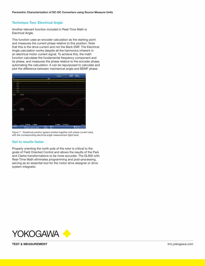
This function uses an encoder calculation as the starting point and measures the current phase relative to this position. Note that this is the drive current and not the Back EMF. The Electrical Angle calculation works despite all the harmonics inherent in an electrical motor current signal. To achieve this, the math function calculates the fundamental frequency component and its phase, and measures the phase relative to the encoder phase, automating the calculation. It can be repurposed to calculate and plot the difference between mechanical angle and BEMF phase.
Figure 7 - Rotational position (green) plotted together with phase current (red), with the corresponding electrical angle measurement (light blue)
Get to results faster
Properly orienting the north pole of the rotor is critical to the goals of Field Oriented Control and allows the results of the Park and Clarke transformations to be more accurate. The DL850 with Real-Time Math eliminates programming and post-processing, serving as an essential tool for the motor drive designer or drive system integrator.