final report performance specification for high
TRANSCRIPT
FINAL REPORT
PERFORMANCE SPECIFICATION FOR HIGH PERFORMANCE CONCRETE OVERLAYS ON BRIDGES
Michael M. Sprinkel, P.E. Associate Director
Virginia Transportation Research Council
(A Cooperative Organization Sponsored Jointly by the Virginia Department of Transportation and
the University of Virginia)
In Cooperation with the U.S. Department of Transportation Federal Highway Administration
Charlottesville, Virginia
August 2004 VTRC 05-R2

ii
DISCLAIMER
The contents of this report reflect the views of the author, who is responsible for the facts and the accuracy of the data presented herein. The contents do not necessarily reflect the official views or policies of the Virginia Department of Transportation, the Commonwealth Transportation Board, or the Federal Highway Administration. This report does not constitute a standard, specification, or regulation.
Copyright 2004 by the Commonwealth of Virginia.

iii
ABSTRACT
Hydraulic cement concrete overlays are usually placed on bridges to reduce the infiltration of water and chloride ions and to improve skid resistance, ride quality, and surface appearance. Constructed in accordance with prescription specifications, some overlays have performed well for more than 30 years whereas others have cracked and delaminated before the overlay was opened to traffic. The use of performance specifications should increase the probability that concrete overlays will be constructed with high bond strengths and minimal cracks and will perform well for many years.
The report describes the Virginia Department of Transportation�s (VDOT) first
experience with the use of a performance specification for the construction and acceptance of a high performance concrete overlay. Acceptance and payment were based on measurements for air content, compressive strength, permeability to chloride ion, and bond strength. Target air contents, high compressive strengths, low permeability, and good bond strengths were maintained throughout the project. Performance specifications with adjustments to the compensation specified in the contract likely influenced decisions made by the contractor and material supplier, and VDOT obtained a better product. VDOT should use the performance specification developed for this project for future bridge overlay projects.

FINAL REPORT
PERFORMANCE SPECIFICATION FOR HIGH PERFORMANCE CONCRETE OVERLAYS ON BRIDGES
Michael M. Sprinkel, P.E.
Associate Director
INTRODUCTION
Hydraulic cement concrete (HCC) overlays are usually placed on bridge decks to reduce the infiltration of water and chloride ions and to improve the skid resistance, ride quality, drainage, and appearance of the surface. The service life of an overlay is usually controlled by the quality of the bond between the overlay and deck. The life of a well-bonded overlay is usually controlled by the time it takes for the overlay to become saturated with chlorides or for chlorides to reach the reinforcement in the deck and cause corrosion-induced spalling. The degree of skid resistance rarely controls the life of an HCC overlay. It is reasonable to expect that the service life of an overlay will increase with an increase in bond strength and a decrease in permeability and the incidence of cracking. High performance concrete (HPC) overlays should be designed to have high bond strength, low permeability to chloride ion, minimal cracks, and good surface characteristics.
Bond Strength of Overlays
Experience has shown that obtaining overlays with high bond strengths is often a problem.1,2 Major overlays have delaminated over large areas before ever being opened to traffic. Others have delaminated prematurely under traffic because of low bond strengths. Surface preparation is generally considered the main factor that affects bond strength. Adequate surface preparation is usually achieved by cleaning the surface to remove anything that can interfere with the bonding of the overlay. It is not usually necessary to remove a considerable depth of concrete to get adequate bond strengths. Concrete is sometimes removed to improve the grade or surface profile prior to placement of the overlay or to allow a thicker overlay to be placed. On older bridge decks, concrete may be deteriorated to the point that major concrete removal is required.
To achieve high bond strengths, the deck surface should be cleaned by shotblasting and other approved cleaning practices to remove asphalt, oils, dirt, rubber, curing compounds, paint, carbonation, laitance, weak surface mortar, and other detrimental materials that might interfere with the bonding or curing of the overlay.
Milling is the most economical way to remove concrete down to the level of the reinforcement. Unfortunately, the impact heads on milling machines typically fracture the surface left in place. Figure 1 shows fractures caused by a new deck being milled before the

2
Figure 1. Fractures Caused by Milling New Deck Prior to Placing Overlay. overlay is placed. The fractures are just below the bond interface between the deck and the overlay. The fractures reduce the strength of the bond between the overlay and deck. When concrete decks are milled prior to placement of the overlay, the bond strength of the overlay is usually controlled by the fractured concrete surface. The milled surface can be shotblasted or hydroblasted to remove some of the damaged concrete. Bond strengths increase as the damaged concrete is removed, but removing all the damaged concrete is usually not practical. A variety of types and sizes of milling machines is available, and research needs to be done to relate the equipment and procedural aspects of milling to damage so that equipment and procedures can be identified or developed that will limit damage. Smaller impact heads may cause fewer fractures.
Shotblasting is one of the practical ways to prepare concrete surfaces to achieve high bond strengths. The shotblaster abrades the deck surface with shot and vacuums up the shot and concrete cuttings. The shot does not leave fractures in the prepared concrete surface. The speed and number of passes of the shotblaster that provide for adequate bond strength are determined with bond tests. By monitoring these factors, the cleaning operation can be controlled. The shotblaster typically removes up to 1/8 in of the surface, and larger shotblasters can remove up to 1/4 in of the surface.
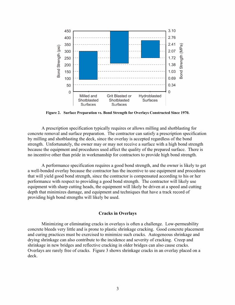
Figure 2 shows bond data collected by the author for HCC overlays placed in Virginia
and Hawaii since 1970. When concrete is milled, follow-up shotblasting is required to clean the surface and remove the damage caused by the milling. Both shotblasting and hydoblasting can yield excellent bond strengths. As Figure 2 suggests, if milling is specified, the risk of low bond strength is high.
3
Figure 2. Surface Preparation vs. Bond Strength for Overlays Constructed Since 1970. A prescription specification typically requires or allows milling and shotblasting for
concrete removal and surface preparation. The contractor can satisfy a prescription specification by milling and shotblasting the deck, since the overlay is accepted regardless of the bond strength. Unfortunately, the owner may or may not receive a surface with a high bond strength because the equipment and procedures used affect the quality of the prepared surface. There is no incentive other than pride in workmanship for contractors to provide high bond strength.
A performance specification requires a good bond strength, and the owner is likely to get
a well-bonded overlay because the contractor has the incentive to use equipment and procedures that will yield good bond strength, since the contractor is compensated according to his or her performance with respect to providing a good bond strength. The contractor will likely use equipment with sharp cutting heads, the equipment will likely be driven at a speed and cutting depth that minimizes damage, and equipment and techniques that have a track record of providing high bond strengths will likely be used.
Cracks in Overlays Minimizing or eliminating cracks in overlays is often a challenge. Low-permeability
concrete bleeds very little and is prone to plastic shrinkage cracking. Good concrete placement and curing practices must be exercised to minimize such cracks. Autogeneous shrinkage and drying shrinkage can also contribute to the incidence and severity of cracking. Creep and shrinkage in new bridges and reflective cracking in older bridges can also cause cracks. Overlays are rarely free of cracks. Figure 3 shows shrinkage cracks in an overlay placed on a deck.

4
Figure 3. Shrinkage Cracks in Overlay Placed on Deck.
A prescription specification typically requires or allows good concrete placement and curing practices. The contractor can satisfy the specification by using the specified curing materials and practices. Unfortunately, the owner may or may not receive an overlay free of cracks because the materials and procedures affect the quality of the cure and the incidence of cracking. A performance specification requires an overlay with few cracks, and the owner is likely to receive a crack-free overlay because the contractor has the incentive to use materials and procedures that will minimize the incidence of cracking, since the contractor is penalized according to his or her performance with respect to providing an overlay without cracks.
Permeability of Overlays
Obtaining overlay concretes with low permeability is typically not a problem.3 The use
of pozzolans and slag as supplemental cementitious materials and good concreting practices easily provide such concretes.
A prescription specification typically requires or allows concrete mixtures that usually
give low permeability. The contractor can satisfy the specification by using an approved mixture. Unfortunately, the owner may or may not receive a low-permeability overlay because the materials and procedures affect permeability. A performance specification requires low permeability, and the owner is likely to receive an overlay with low permeability because the contractor has the incentive to use materials and procedures that will ensure it, since the contractor is compensated according to his or her performance in this regard.
Skid Resistance, Ride Quality, Drainage, and Surface Appearance of Overlays Obtaining overlays with good skid resistance, ride quality, drainage, and surface
appearance is typically not a problem. These factors are easily achieved with good construction
5
practices, and the grooves that are saw cut into the hardened concrete surface ensure good skid resistance.
A prescription specification typically requires the contractor to construct overlays with
good skid resistance, ride quality, drainage, and surface appearance. The contractor can satisfy the specification by using approved materials, procedures, and equipment. Unfortunately, the owner may or may not receive the desired overlay because the materials, procedures, and equipment affect the result. A performance specification requires good skid resistance, ride quality, drainage, and surface appearance, and the owner is likely to receive such an overlay because the contractor has the incentive to use materials and procedures that will ensure it, since the contractor is compensated according to his or her performance in this regard. VDOT recently implemented the use of a ride specification for bridge decks that should be applicable for overlays, and the ride requirements should be added to the performance specification for overlays. Performance specifications for skid resistance, drainage and surface appearance should also be added to the performance specification for overlays.
VDOT�s Special Provision for Hydraulic Cement Concrete Overlays
Constructed in accordance with prescription specifications,4 some overlays have performed well for more than 30 years whereas others have cracked and delaminated before the overlay was opened to traffic. HPC overlays have high bond strengths and minimal cracks and should perform well for more than 30 years. Constructing a high-quality HPC overlay requires that appropriate decisions be made with respect to the selection and use of surface preparation equipment and procedures, mixture proportions, and placement and curing procedures. The use of performance specifications should increase the probability that concrete overlays will be constructed with high bond strengths and minimal cracks and will perform well for many years.
In November 2002, VDOT put into place a performance specification for HCC overlays.
The specification took the form of a Special Provision for Determining Adjustments to Contract Compensation for Hydraulic Cement Concrete Overlays and is provided in the Appendix. The special provision requires that overlay mixtures conform to the following quality acceptance limits (QAL). These QAL are used for calculating adjustments to contract compensation. Air Content
The lower quality limit (LQL) and upper quality limit (UQL) for air content (ASTM C 138, ASTM C 173, or ASTM C 231) is a function of the overlay type. The LQL and UQL for air content are 4.0 percent and 8.0 percent for 7 percent silica fume; 3.0 percent and 7.0 percent for 15 percent latex-modified; and 4.0 and 8.0 percent for other HCC overlays. The air content is determined by one test by the Engineer from each sublot. Compressive Strength
The LQL for compressive strength is the design compressive strength (ASTM C 39) at 28 days plus 300 psi. The design compressive strength is a function of the overlay type. The design

6
strengths are 5,000 psi for 7 percent silica fume, 3,500 psi for 15 percent latex-modified, and 4,000 psi for other HCC overlays. The LQL is 5,300 psi for a silica fume overlay. The strength is defined as the average of tests on three 4- by 8-in cylinders cast, cured, and tested by the Engineer from each sublot. Permeability
The UQL for permeability is 1000 coulombs (AASHTO T 277) at 28 days. Permeability is defined as the average of tests on two 4- by 8-in cylinders cast, cured, and tested by the Engineer from each sublot. Two-inch-thick samples are cut from the center of each cylinder for testing. Accelerated curing procedures are used. Except for latex-modified concrete, cylinders are moist cured for the first week in a moist room at 73 F and in saturated limewater at 100 F for the next 3 weeks. Latex-modified cylinders are moist cured for the first 2 days and air cured for the next 5 days in the lab at 73 F. The cylinders are air cured in an oven at 100 F for the next 3 weeks. The accelerated curing provides permeability values at 28 days that are comparable to the permeability values that will be obtained at 90 days to 1 year in the in-place overlay concrete. Bond Strength
The LQL for bond strength (ACI 503R-93) 6 is 150 psi at 28 days. The bond strength between the overlay and existing concrete is defined as the average of tests on three 2- to 4-inch-diameter cores cut and tested by the Engineer from each sublot. The equipment for testing bond strength is shown in Figure 4. The cores are cut and tested after the overlay has exceeded the design compressive strength, after the curing of the overlay is complete, and prior to the overlay being opened to traffic. The cores are cut 1 in into the existing concrete to isolate the overlay concrete. Locations for each test are randomly determined by the Engineer. For tests that result in a failure in the base concrete at a depth of ¼ in or more over greater than 50 percent of the test area and a test value of less than 150 psi, the bond strength is assigned a value of 150 psi when the average is computed. When more than 50 percent of the tests result in a failure in the base concrete at a depth of ¼ in or more over greater than 50 percent of the test area and a test value of less than 150 psi, the percent within limits (PWL) is the greater of 55 or the calculated value.
Figure 4. Overlay Being Tested for Tensile Bond Strength.

7
Delaminations
The total surface area is tested using the chain drag test (ASTM D 4580-86) prior to opening of the overlay to traffic. Delaminated areas must be replaced by the contractor at no additional cost to the owner. If the Engineer elects to accept the concrete, the contractor will be compensated at 50 percent of the contract unit price for the HCC specified. Pattern Cracking
Overlay concrete for any given sublot in which the cracks are within 1 in of the bond interface must be removed. Cracks that are not within 1 in of the bond interface must be filled with a gravity fill polymer in accordance with VDOT�s Special Provision for Gravity Fill Polymer Crack Sealing. If the Engineer elects to accept the concrete, the contractor will be compensated at 50 percent of the contract unit price for the HCC specified.
Linear Cracking
Overlay concrete for any given sublot in which the cracks are within 1 in of the bond interface or in which the frequency of cracking exceeds 0.12 foot per square foot must be removed. Cracks that are not within 1 in of the bond interface and in which the frequency of cracking is less than or equal to 0.12 foot per square foot must be filled with a gravity fill polymer in accordance with VDOT�s Special Provision for Gravity Fill Polymer Crack Sealing. If the Engineer elects to accept the concrete, the contractor will be compensated at 50 percent of the contract unit price for the HCC specified. Correction for Other Deficiencies
The specification requires that concrete be removed and replaced at no additional cost to VDOT if the PWL for compressive strength, permeability, or bond strength is below 55; the calculated average of any three consecutive compressive strength samples does not equal or exceed the design compressive strength; or the compressive strength test result for any sample is below the design compressive strength by more than 500 psi. If either of the latter two conditions is present, the in-place compressive strength must be investigated in accordance with ACI 318-99, Section 5.6.5, at no additional cost to VDOT. Final decisions will be based on the investigation. If the Engineer elects to accept the concrete, the contractor will be compensated at 50 percent of the contract unit price for the HCC specified regardless of the pay factors (PFs) calculated. Adjustments to Contract Compensation
PFs are multiplied by the contract unit price for the HCC specified. The result is the amount to be compensated to or deducted from the payment to the contractor for the particular lot of concrete. For 91 to 100 PWL, the PF = 0.006 x (PWL � 90); for 85 to 90 PWL, the PF = 0.0; and for 55 to 84 PWL, the PF = �0.9 + (0.01 x PWL).

8
PURPOSE AND SCOPE
The purpose of this study was to evaluate VDOT�s first experience with the use of a performance specification for the construction and acceptance of an HPC overlay.5
METHODS
The overlay was placed on the two northbound lanes of the six-span bridge on Route 29
over the Rockfish River in Virginia (Project 0029-062-1123, SR02). Acceptance and payment were based on measurements for air content, compressive strength, permeability to chloride ion, and bond strength in accordance with VDOT�s Special Provision for Determining Adjustments to Contract Compensation for Hydraulic Cement Concrete Overlays (see the Appendix).
The inside lane was placed on April 29, 2003, and the outside lane on July 15, 2003. The
project was divided into four sublots. Each sublot included three spans in one lane. Type A milling to remove the top 0.5 in of the old surface was a pay item. Surface preparation by shotblasting was included in the overlay price.
An effort was made to evaluate alternative concrete removal equipment. Two milling
machines (Cat and Roadtec) were driven at two speeds on the inside lane. Figure 5 shows the impact heads on the Roadtec milling machine used to mill the northern half of the inside lane. A work order was administered so that diamond grinding was used to remove concrete on the outside lane. Following the milling and grinding, concrete was removed from areas requiring patching, and patches were constructed with the same concrete mixture used in the overlay. Prior to placement of the overlay, patches were shotblasted along with the rest of the deck. The entire deck was wetted and covered with polyethylene following the shotblasting. The polyethylene was removed and the deck wetted again as needed to provide a saturated surface dry deck ahead of the overlay placement.
Figure 5. Impact Heads on Roadtec Milling Machine.

9
Mixture proportions used in the overlay are shown in Table 1.
Table 1. Mixture Proportions for 7 Percent Silica Fume Overlay
Constituent Amount Cement, lb/yd3 658 Silica fume, lb/yd3 46 Fine aggregate, lb/yd3 1269 Coarse aggregate, lb/yd3 1516 Water, lb/yd3 282 Air, % 7
The evaluation of the overlay was based on the preparation and testing of specimens for air content, compressive strength, permeability to chloride ion, and bond strength as described in the Introduction section. For bond strength, the inside lane (sublots 1 and 2) was tested on May 9, 2003, and the outside lane (sublots 3 and 4) on July 24, 2003. The core diameter was 2.375 in, and the core depth was 2.73 in.
The overlay was also checked for delaminations and cracks as described in the Introduction.
RESULTS AND DISCUSSION
Slump, Air Content, and Temperature
Results for slump for the four sublots are shown in Table 2. Although the requirements for slump were 4 to 7 in, the contractor chose to place the concrete in three of the sublots at a slump slightly less than 4 in. To increase the slump, the contractor would have added water. Adding water lowers strength and increases permeability, involving two pay items. Adding water also increases shrinkage, which influences cracking, an acceptance item. The performance specification with adjustments to contract compensation likely influenced the contractor�s decision made not to add water. With a prescription specification, the contractor would likely have added water and VDOT would have obtained an overlay with lower strength, higher permeability, and possibly more cracks.
Table 2. Results for Slump, Air Content, and Temperature for the Four Sublots
Sublot
Slump (in)
Air Content (%)
Concrete Temperature (F)
Air Temperature (F)
Inside lane 1 avg. 3.75 6.8 73 70 2 avg. 3.50 6.0 74 82 Outside lane 3 3.50 5.2 77 63 4 5.25 5.4 75 61

10
Results of air content for the four sublots are shown in Table 2. The LQL and UQL for air content were 4.0 and 8.0 percent for 7 percent silica fume. The average for the four sublots was 5.85 percent, and the standard deviation was 0.7188 percent. The air content of sublot 1 was higher than 6.0 percent, the middle of the specified range. The material supplier adjusted the concrete, and the air content for sublot 2 was exactly 6.0 percent. The air contents for sublots 3 and 4 were lower, so that the average for the four sublots was 5.85 percent, the middle of the specified range. Again, adjustments to contract compensation likely influenced decisions on air content made by the contractor and material supplier, and VDOT got a better product.
Table 2 shows that the concrete satisfied the requirements for temperature of 50 F to
85 F.
Compressive Strength
The LQL for compressive strength was the design compressive strength (ASTM C 39) at 28 days, plus 300 psi. The LQL for the silica fume overlay constructed was 5,300 psi. Results for compressive strength for the four sublots are shown in Table 3. The average values for each sublot were 8,200, 8,882, 8,930, and 9,064 psi. The average for the four sublots was 8,769 psi, and the standard deviation was 387 psi. High strengths were maintained throughout the project. Adjustments to contract compensation likely influenced decisions made by the contractor and material supplier, and VDOT got a better product.
Table 3. Results for Compressive Strength
Cylinder No. (inside lane)
Compressive Strength at 28 Days (lb/in2)
Cylinder No. (outside lane)
Compressive Strength at 28 Days (lb/in2)
3 8,165 5A 8,956 3A 8,288 5B 8,807 3B 8,244 5C 9,172 Set 1 avg. 8,232 Set 1 avg. 8,978 3C 8,099 5D 8,810 3D 8,027 5E 8,907 3E 8,382 5F 8,926 Set 2 avg. 8,169 Set 2 avg. 8,881 Sublot 1 avg. 8,200 Sublot 3 avg. 8,930 4C 8,989 6A 9,012 4D 8,704 6B 9,135 4E 8,953 6C 9,181 Set 3 avg. 8,882 Set 3 avg. 9,109 - - 6D 9,033 - - 6E 8,933 - - 6F 9,088 - - Set 4 avg. 9,018 Sublot 2 avg. 8,882 Sublot 4 avg. 9,064

11
Permeability
The UQL for permeability was 1000 coulombs (AASHTO T 277) at 28 days. Results for permeability are shown in Table 4. The average values for each sublot were 778, 847, 407, and 697 coulombs. The average for the four sublots was 682 coulombs, and the standard deviation was 194 coulombs. Very low permeability was maintained throughout the project. Adjustments to contract compensation likely influenced decisions made by the contractor and material supplier, and VDOT got a better product.
Table 4. Results for Permeability
Cylinder No. (inside lane)
Permeability at 28 Days (coulombs)
Cylinder No. (outside lane)
Permeability at 28 days (coulombs)
3F 758 5G 401 3G 798 5H 395 Sublot 1 avg. 778 Sublot 3 avg. 407 4F 812 6G 705 4G 881 6H 712 Sublot 2 avg. 847 Sublot 4 avg. 697
Bond Strength
The LQL for bond strength (ACI 503R-93) was 150 psi at 28 days. The results for bond strength are shown in Table 5. The average values for each sublot were 208, 170, 175, and 207 psi. The average for the four sublots was 190 psi, and the standard deviation was 20.3 psi. The Lower Quality Index (LQI) was 1.969. For N = 4, the PWL was 100 percent. Voids were noted in the overlay at the bond interface in most cores. The voids were likely caused by entrapped air or water sprayed on the surface prior to placement of the overlay. The voids likely caused a reduction in bond strength. Good bond strength was maintained throughout the project.
The tensile bond strength test results as a function of concrete removal equipment are
shown in Table 6. If it is assumed that shotblasting does no damage, bond strengths should be as least as high as they were for the patches (202 psi). All results were acceptable. The methods were not significantly different at a high confidence level. Evaluations of other bridges are necessary to try to duplicate the results.
Delaminations, Pattern Cracking, and Linear Cracking
No delaminations, pattern cracking, or linear cracking was found.

12
Table 5. Tensile Bond Strength, Failure Location, and Overlay Thickness at Test Locations
Sublot Test Span Failure Failure Base Base Failure Overlay1 1�1A 4.3 219 50 - 1 7/16 1 1�2 3.9 198 50 - 1 5/8 1 2�3A 3.4 173 50 - 1 1/2 1 2�4 3.95 201 50 - 1 1/2 1 3�5 4.3 219 15 - 1 1/2 1 3�6 4.7 239 50 - 1 7/16 2 4�7 4.65 236 70 - 1 1/2 2 4�8B 3.15 160 40 - 1 1/2 2 5�9B 2.85 145 15 - 1 9/16 2 5�10A 3.05 155 80 - 1 7/16 2 6�11 2.8 142 50 - 1 9/16 2 6�12 3.6 183 50 - 1 1/4 1 1�1 Coring - 50 - 1 1/2 1 2�3 Coring - 30 - 1 1/2 2 4�8 Coring - 100 >50 1 1/2 2 4�8A Coring - 50 - 1 9/16 2 5�9 Coring - 50 - 1 9/16 2 5�9A Coring - 100 100 1 9/16 2 5�10 Coring - 90 90 1 1/2 1A Average - 197 - - - 1B Average - 220 - - - 1 Average - 208 - - - 2A Average - 180 - - - 2B Average - 160 - - - 2 Average - 170 - - - 1 & 2 Average - 189 3 1�1G 2.1 101 80 - 2 3 2�2G 4.6 222 80 - 1 9/16 3 3�3G 3.6 174 15 - 1 3/4 3 1�1P 3.3 159 30 - 1 5/8 3 2�2P 4.2 203 25 - 1 3/8 3 3�3P 4.0 193 45 - 2 3/8 4 4�4G 4.3 207 50 - 1 1/2 4 5�5G 4.0 193 70 - 1 1/2 4 6�6G 3.9 188 55 - 1 3/4 4 4�4P 4.8 231 50 - 2 1/4 4 5�5P 4.2 203 45 - 1 1/4 4 6�6P 4.6 222 75 - 1 3/4 3G Average - 166 - - - 3P Average - 185 - - - 3 Average - 175 - - - 4G Average - 196 - - - 4P Average - 219 - - - 4 Average - 207 - - - 3 & 4 G Average - 181 - - - 3 & 4 P Average - 202 - - - 3 & 4 Average - 191 - - - 1,2,3,4 Average - 190 - - - 1,2,3,4 SD - 20.3 - - -

13
Table 6. Average Tensile Bond Test Results (psi) and % Base Failure as Function of Concrete Removal Method and Equipment
Concrete Removal Method
Lane
Average s
Average % Base
s
Cat @ 2�4 ft/min (slow) Inside 197 23 50 0 Cat @ 11 ft/min Inside 220 19 38 20 Roadtec @ 20 ft/min Inside 180 49 42 28 Roadtec @ 2�4 ft/min (slow) Inside 160 21 60 17 Diamond grinding Outside 181 42 58 25 Shotblasted patch Outside 202 25 45 18
Adjustments to Contract Compensation
The data and calculations necessary to compute adjustments to contract compensation are shown in Table 7. The average PWL was 100 percent, and the PF was +6 percent.
Table 7. Adjustments to Contract Compensation
Overlay Concrete
Performance Properties
Average 28-day
Compressive Strength (psi)
Average
Permeability (coulombs)
Average Bond Strength (psi)
Average Plastic Air Content (%)
Sublot 1 8,200 778 208 6.8 Sublot 2 8,882 847 170 6.0 Sublot 3 8,930 407 175 5.2 Sublot 4 9,064 697 207 5.4 Average, 4 sublots
8,769 682.25 190 5.85
SD, 4 sublots 387 193.5 20.3 0.7188 LQL 5,300 150 4.0 UQL 1000 8.0 LQI (8,769 � 5,300)/387
= 8.96 (190 � 150)/20.3
= 1.969 (5.85 � 4.0)/0.7188 = 2.574
UQI (1000 � 682.25)/ 193.5 = 1.642
(8.0 � 5.85)/0.7188 = 2.991
PWL, lower (8.96 > 1.50 for N = 4) = 100
(1.969 > 1.50 for N = 4) = 100
(2.574 > 1.50 for N = 4) = 100
PWL, upper (1.642 > 0.50 for N = 4) = 100
2.991 > 1.50 for N = 4) = 100
PWL, lower and upper
100 + 100 � 100 = 100
Average PWL 100 + 100 + 100 + 100 = 100 PF (91 - 100) = [0.006(100 - 90)] = +0.06 = +6%
SD = standard deviation; LQL = lower quality limit; UQI = upper quality limit; LQI = lower quality index; UQI = upper quality index; PWL = percent within limits; PF = pay factor.
14
Cost
The bid price for the overlay was $35.70 per square yard. With the 6 percent bonus, the cost was $37.84 per square yard. The average bid price for overlays in VDOT�s Lynchburg District was $41.76 per square yard. The project was bid 15 percent less than the average, and the cost was 9 percent less than the average.
CONCLUSIONS
Successful HPC overlays require good surface preparation that provides high bond strength; quality mixture proportions that provide low shrinkage and low permeability; proper placement that includes adequate consolidation and low evaporation rates; and good curing that minimizes cracking. Target air contents, high compressive strengths, very low coulomb values, and good bond strengths were maintained throughout the project. Adjustments to contract compensation likely influenced decisions made by the contractor and material supplier, and VDOT obtained a better product.
RECOMMENDATIONS 1. VDOT should use the performance specification developed for this project for future bridge
overlays. 2. VDOT should add requirements for ride, skid resistance, drainage, and surface appearance to
the performance specification.
REFERENCES 1. Sprinkel, M.M. High Performance Concrete Overlays for Bridges. In Proceedings,
Prestressed Concrete Institute Convention/National Bridge Conference/Federal Highway Administration Symposium on High Performance Concrete, Orlando, Fla., October 19-22, 2003. Portland Cement Association, Skokie, Ill.
2. Sprinkel, M.M. Preparing Bridge Decks for Overlays. Concrete Repair Digest, Vol. 8, No.
5, 1997, pp. 242-247. 3. Sprinkel, M.M., and Ozyildirim, C. Evaluation of High Performance Concrete Overlays
Placed on Route 60 Over Lynnhaven Inlet in Virginia. VTRC 01-R1. Virginia Transportation Research Council, Charlottesville, 2000.
4. Virginia Department of Transportation. Road and Bridge Specifications. Richmond, 2002.

15
5. Virginia Department of Transportation. Special Provision for Determining Adjustments to Contract Compensation for Hydraulic Cement Concrete Overlays. Richmond, November 5, 2002.
6. American Concrete Institute. Manual of Concrete Practice, Part 5, Use of Epoxy
Compounds with Concrete. ACI 503R-93. Farmington Hills, Mich., 1993.


17
APPENDIX
VIRGINIA DEPARTMENT OF TRANSPORTATION SPECIAL PROVISION FOR
DETERMINING ADJUSTMENTS TO CONTRACT COMPENSATION FOR HYDRAULIC CEMENT CONCRETE OVERLAYS
November 5, 2002
PART 1 - GENERAL
1.01 SUMMARY
This Special Provision specifies the requirements for end result properties of in-place concrete in Hydraulic Cement Concrete Overlays and the evaluation of these properties through Quality Acceptance testing performed by the Department for determining adjustments to contract compensation for this item of work. The specifications herein establish minimum standards for concrete construction. This does not relieve the Contractor from following more stringent standards to achieve the quality acceptance limits for applicable performance parameters and their respective Percent Within Limit (PWL) measurements.
1.02 QUALITY CONTROL
A. General
1. The Contractor shall provide and maintain a process Quality Control Plan, hereinafter referred
to as the �Plan.� The Plan shall include a list and function of all personnel, equipment, supplies, and facilities necessary to obtain Quality Control samples, perform tests, and otherwise control the quality of the product to meet specified requirements.
PART 2 � QUALITY ACCEPTANCE
2.01 QUALITY ACCEPTANCE LIMITS
A. Overlay mixtures shall conform to the following performance Quality Acceptance Limits in accordance with the relevant application properties specified in 4.01.B., Table 2, unless otherwise noted on the Contract Drawings:
1. Compressive Strength (ASTM C 39): The Lower Quality Limit (LQL) shall be the design
compressive strength at 28 days, plus 300 psi. 2. Permeability (AASHTO T 277): The Upper Quality Limit (UQL) shall be 1000 Coulombs at
28 days. 3. Bond Strength [ACI 503R-93 � Appendix A (Modified)]: The Lower Quality Limit (LQL)
shall be 150 psi at 28 days. 4. Air Content (ASTM C 138, ASTM C 173 or ASTM C 231): Both the Lower Quality Limit
(LQL) and the Upper Quality Limit (UQL) shall be as specified in Table 1:

18
TABLE 1 AIR CONTENT TARGET RANGE FOR FRESHLY MIXED CONCRETE, (Percent)
Overlay Concrete LQL UQL Latex-modified 3.0 7.0 Silica fume 4.0 8.0 Other hydraulic cement concrete 4.0 8.0
5. Delaminations: The total surface area shall be tested using the chain drag in accordance
with ASTM D 4580-86. 6. Pattern Cracking: Overlay concrete for any given sublot in which the cracks are within 1
inch of the bond interface shall be removed. (Refer to Part 4, paragraph G) Cracks that are not within 1 inch of the bond interface shall be filled with a gravity fill polymer in accordance with the VDOT Special Provision for Gravity Fill Polymer Crack Sealing.
7. Linear Cracking: Overlay concrete for any given sublot in which the cracks are within 1
inch of the bond interface or in which the frequency of cracking exceeds 0.12 foot per square foot shall be removed. (Refer to Part 4, paragraph G herein) Cracks that are not within 1 inch of the bond interface and in which the frequency of cracking is less than or equal to 0.12 foot per square foot shall be filled with a gravity fill polymer in accordance with the VDOT Special Provision for Gravity Fill Polymer Crack Sealing.
B. Unless otherwise specified on the Contract Drawings, the above specified quality acceptance
limits shall be used for calculating adjustments to contract compensation in accordance with Part 4 of this special provision.
PART 3 - EXECUTION
3.01 QUALITY ACCEPTANCE TESTING, SAMPLING, AND INSPECTIONS
A. Quality acceptance testing during mixing and placing of concrete will be performed on samples taken from the end of the pump line or at the point of discharge in accordance with ASTM C 172. The Engineer will take samples of concrete from each Lot during a single work period based on random sampling procedures contained in ASTM D 3665 for each class of concrete being placed. This project shall consist of one (1) lot with two (2) sublots per stage for a total of four (4) sublots. For each Sublot, six (6) cylinders will be made in accordance with ASTM C 31 when testing for compressive strength, as well as, two (2) 4x8 cylinders when permeability is being tested. The cylinders will be tested in accordance with ASTM C 39 for each Sublot to determine the compressive strength.
B. Quality Acceptance Testing Standards and Frequency of Testing: Some, or all, of the following
procedures will be used by the Engineer to evaluate the in-place concrete for Adjustments to Contract Compensation:
1. Compressive Strength: Cylinders made and cured in accordance with ASTM C 31 and
ACI 318-99 - Part 3, Chapter 5, Item 5.6, entitled "Evaluation and Acceptance of Concrete", except that samples will be obtained on a random basis with a minimum of six (6) cylinders prepared for each Sublot. Latex Modified Concrete samples shall be wet cured for 2 days and dry cured for 26 days. The cylinders will be tested in accordance with ASTM C 39. Three compressive strength samples shall be obtained from each sublot on a randomly selected basis. A sample is defined as the average of 2 cylinders for strength.

19
2. Slump Test: Performed at the point of delivery during the time of placement in accordance with ASTM C 143. For Latex Modified Concrete, slump tests shall be performed 5 minutes after sampling from the mixer. Slump shall be in accordance with Section 217 of the Specifications.
3. Air Content Test: Performed during the placement in accordance with ASTM C 138, ASTM C 173 or ASTM C 231. The Engineer will perform one test for each Sublot, which will be considered the Sublot air content test value.
4. Permeability; Coulomb Test: To evaluate the permeability of the concrete.
a. Latex-modified concrete: samples shall be moist cured 2 days in the molds (1 day
at job site and 1 day in the lab), air cured 5 days in the molds in the laboratory, and 21 days out of the molds at 100°F air temp.
b. Silica Fume and other non-latex samples shall be moist cured 7 days in the molds
(1 day at job site and 6 days in the lab) and moist cured 21 days out of the molds in the laboratory at 100°F water temperature.
c. For each Sublot, the Engineer will cast two (2) 4 x 8 cylinder specimens. Two-
inch thick samples will be cut from the center of each cylinder for testing. The average of the two (2) test specimen result values for each Sublot will be considered the Sublot Coulomb test value for permeability.
5. Bond Strength: The bond strength between the overlay concrete and the existing
concrete shall be evaluated in accordance with ACI 503R-93 � Appendix A or VTM 92. For each Sublot, the Engineer will perform three (3) tests. Three (3) 2 to 4-inch diameter cores will be cut 1-inch into the existing concrete to isolate the overlay concrete. The average of the three test result values for the Sublot will be considered the Sublot bond strength test value. The locations for each test will be randomly determined by the Engineer. Tests that result in a failure in the base concrete at a depth of ¼ inch or more over greater than 50 percent of the test area and a test value of less than 150 psi shall be assigned a value of 150 psi when computing the average. When more than 50 percent of the tests result in a failure in the base concrete at a depth of ¼ inch or more over greater than 50 percent of the test area and a test value of less than 150 psi the PWL shall be the greater of 55 or the calculated value.
PART 4 � ADJUSTMENTS TO CONTRACT COMPENSATION
4.01 GENERAL
A. Unless otherwise shown on the Contract Drawings, acceptance of material shall be based on the method of estimating PWL, where the PWL will be determined in accordance with this Section. All Sublot test result values for a Lot, as defined in 3.01.A., will be analyzed statistically to determine the total estimated PWL, as shown in 4.01.B. The PWL is computed using the Lot sample average value, X , as defined in 4.01.D.3, the Lot sample standard deviation, SN, as defined in 4.01.D.4, for the specified number of Sublots, n, and the specification Quality Acceptance Limits, as defined in 2.01.A., where LQL represents the Lower Quality Limit, and UQL represents the Upper Quality Limit, as they apply to each particular acceptance parameter. From these values, the respective Quality Index (Indices), QL for Lower Quality Index and/or QU for Upper Quality Index, is (are) computed in accordance with 4.01.D.5. and 4.01.D.6. Then the PWL for the Lot for the specified number of Sublots, n is determined from Table 4, �Percent of Lot Within Limits (PWL) (Standard Deviation Method).� The adjustment to contract compensation for each Lot is then calculated using the formulas specified in 4.01.F.

20
B. Dependent on the application, concrete shall be tested for the properties shown below. The PWL of each Lot for each parameter will be determined as specified in 4.01.D. Payments shall be based on the criteria defined below.
Performance Parameters Minimum PWL Compressive Strength 85 Permeability 85 Bond Strength 85 Air Content 80
C. In addition, all concrete shall conform to the requirements of 4.01.G. Any deficiencies found to exist as specified in 4.01.G. shall govern, and the Contractor shall either:
1) remove and replace the concrete in that particular Lot at no cost to the Department, or 2) accept a deduction of 50% of the contract unit price for that particular Lot of concrete.
D. Method of estimating PWL:
1. Locate sampling positions on the Lot by use of random sampling procedures specified in 3.01.A.
2. Take a test sample and make the test specimens on the test sample in accordance with
3.01.B. 3. Determine the Lot sample average value, X , by calculating the average of all Sublot test
values. 4. Find the Lot sample standard deviation, Sn, by using the following formula:
2( )
1i
nx X
Sn
−=
−∑
Where: Sn = standard deviation of the Sublot test values xi = individual Sublot test values X = Average of Sublot test values n = number of Sublots
5. Find the Lower Quality Index, QL, by subtracting the Lower Quality Limit, LQL, from the
Average value, X , and dividing the result by Sn.
QL = X - LQL Sn
6. Find the Upper Quality Index, QU, by subtracting the Lot sample average value, X , from the Upper Quality Limit, UQL, and dividing the result by Sn.
QU = UQL - X
Sn
21
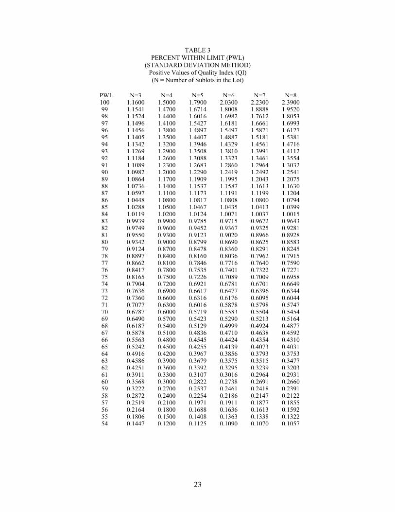
7. The percentage of material above lower tolerance limit, PL, and the percentage of material below upper tolerance limit, PU, will be found by entering Table 3, �Percent Within Limit (PWL) (Standard Deviation Method)� with QL and/or QU using the column appropriate to the total number of Sublots, n, and reading the appropriate number under the column heading �PWL.�
8. For concrete properties with only an Upper Quality Limit (i.e., permeability), PWL equals
PU. For concrete properties with a Lower Quality Limit (i.e., bond strength, compressive strength), PWL equals PL. For concrete properties with both Upper and Lower Quality Limits (i.e., air content), first calculate of the Upper Quality Index, QU, and the Lower Quality Index, QL, by using the Upper Quality Limit, UQL, and the Lower Quality Limit, LQL, respectively. The limits to be used are stipulated in 2.01.A. Then determine PWL using the following formula:
PWL = (PU + PL) - 100
9. The PWL from Table 3 that is to be used is the whole number greater than that found by using the QU or QL in the table. Example: the PWL to be used for n= 4 and a QU of 1.4200 would be 98.
E. Pay Factor Adjustments
1. Pay Factor adjustments for each Lot will be computed in accordance with the formulas
contained in 4.01.F., Table 2 entitled, �Adjustments to Contract Compensation�, by entering the PWL value and performing the calculation indicated for the appropriate PWL range to determine the Pay Factor.
2. The PWL values for compressive strength, permeability, bond strength, and air content for
each lot will be averaged to determine the value to be used for the Pay Factor Adjustment.
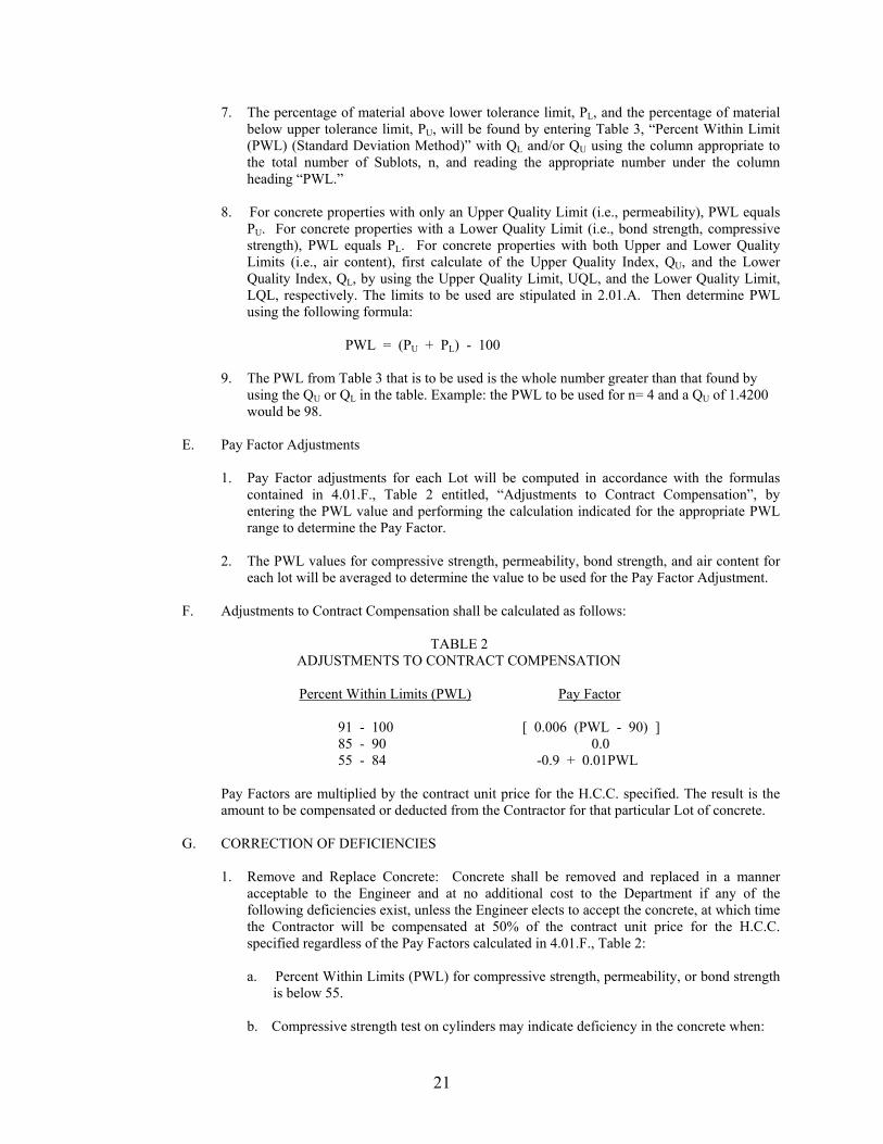
F. Adjustments to Contract Compensation shall be calculated as follows:
TABLE 2 ADJUSTMENTS TO CONTRACT COMPENSATION
Percent Within Limits (PWL) Pay Factor
91 - 100 [ 0.006 (PWL - 90) ] 85 - 90 0.0 55 - 84 -0.9 + 0.01PWL
Pay Factors are multiplied by the contract unit price for the H.C.C. specified. The result is the amount to be compensated or deducted from the Contractor for that particular Lot of concrete.
G. CORRECTION OF DEFICIENCIES
1. Remove and Replace Concrete: Concrete shall be removed and replaced in a manner
acceptable to the Engineer and at no additional cost to the Department if any of the following deficiencies exist, unless the Engineer elects to accept the concrete, at which time the Contractor will be compensated at 50% of the contract unit price for the H.C.C. specified regardless of the Pay Factors calculated in 4.01.F., Table 2:
a. Percent Within Limits (PWL) for compressive strength, permeability, or bond strength
is below 55. b. Compressive strength test on cylinders may indicate deficiency in the concrete when:

22
1. The calculated average of any three consecutive compressive strength sample does not equal or exceed the design compressive strength.
2. Any individual sample�s compressive strength test result is below the design
compressive strength by more than 500 psi. 3. If either of the conditions in 4.01.G.1.b.1. or 4.01.G.1.b.2. is present, the in-place
compressive strength shall be investigated in accordance with ACI 318-99, Section 5.6.5, at no additional cost to the Department. If the compressive strength test results of the in-place concrete meet either, or both of the conditions in 4.01.G.1.b.1. and/or 4.01.G.1.b.2., the concrete shall be considered deficient, and 4.01.G.1. shall apply.
c. Concrete overlays that exhibit any cracks prior to opening to public traffic or loading
shall be subject to the actions specified in Section 4.01.G.1. If the concrete is otherwise acceptable to the Engineer, cracks shall be sealed as specified herein in a manner satisfactory to the Engineer, and at no cost to the VDOT.
1. Pattern Cracking: Overlay concrete for any given sublot in which the cracks are
within 1 inch of the bond interface shall be removed. Cracks that are not within 1 inch of the bond interface shall be filled with a gravity fill polymer in accordance with the VDOT Special Provision for Gravity Fill Polymer Crack Sealing.
2. Linear Cracking: Overlay concrete for any given sublot in which the cracks are
within 1 inch of the bond interface or in which the frequency of cracking exceeds 0.12 foot per square foot shall be removed. Cracks that are not within 1 inch of the bond interface and in which the frequency of cracking is less than or equal to 0.12 foot per square foot shall be filled with a gravity fill polymer in accordance with the VDOT Special Provision for Gravity Fill Polymer Crack Sealing.
d. Delamination Testing � All concrete overlays shall be checked by the Engineer using
the chain drag method in accordance with ASTM 4580-86 no sooner than 24 hours and no greater than 30 days after the completion of the Work. Unsound areas will be identified. If any delaminations are identified, the Contractor shall remove the areas evidencing delamination between the fresh concrete overlay and the existing concrete. These areas shall be replaced at no cost to the Department. The determination by the Engineer as to the existence of delaminations shall be final and binding.
23
TABLE 3 PERCENT WITHIN LIMIT (PWL)
(STANDARD DEVIATION METHOD) Positive Values of Quality Index (QI) (N = Number of Sublots in the Lot)
PWL N=3 N=4 N=5 N=6 N=7 N=8100 1.1600 1.5000 1.7900 2.0300 2.2300 2.390099 1.1541 1.4700 1.6714 1.8008 1.8888 1.952098 1.1524 1.4400 1.6016 1.6982 1.7612 1.805397 1.1496 1.4100 1.5427 1.6181 1.6661 1.699396 1.1456 1.3800 1.4897 1.5497 1.5871 1.612795 1.1405 1.3500 1.4407 1.4887 1.5181 1.538194 1.1342 1.3200 1.3946 1.4329 1.4561 1.471693 1.1269 1.2900 1.3508 1.3810 1.3991 1.411292 1.1184 1.2600 1.3088 1.3323 1.3461 1.355491 1.1089 1.2300 1.2683 1.2860 1.2964 1.303290 1.0982 1.2000 1.2290 1.2419 1.2492 1.254189 1.0864 1.1700 1.1909 1.1995 1.2043 1.207588 1.0736 1.1400 1.1537 1.1587 1.1613 1.163087 1.0597 1.1100 1.1173 1.1191 1.1199 1.120486 1.0448 1.0800 1.0817 1.0808 1.0800 1.079485 1.0288 1.0500 1.0467 1.0435 1.0413 1.039984 1.0119 1.0200 1.0124 1.0071 1.0037 1.001583 0.9939 0.9900 0.9785 0.9715 0.9672 0.964382 0.9749 0.9600 0.9452 0.9367 0.9325 0.928181 0.9550 0.9300 0.9123 0.9020 0.8966 0.892880 0.9342 0.9000 0.8799 0.8690 0.8625 0.858379 0.9124 0.8700 0.8478 0.8360 0.8291 0.824578 0.8897 0.8400 0.8160 0.8036 0.7962 0.791577 0.8662 0.8100 0.7846 0.7716 0.7640 0.759076 0.8417 0.7800 0.7535 0.7401 0.7322 0.727175 0.8165 0.7500 0.7226 0.7089 0.7009 0.695874 0.7904 0.7200 0.6921 0.6781 0.6701 0.664973 0.7636 0.6900 0.6617 0.6477 0.6396 0.634472 0.7360 0.6600 0.6316 0.6176 0.6095 0.604471 0.7077 0.6300 0.6016 0.5878 0.5798 0.574770 0.6787 0.6000 0.5719 0.5583 0.5504 0.545469 0.6490 0.5700 0.5423 0.5290 0.5213 0.516468 0.6187 0.5400 0.5129 0.4999 0.4924 0.487767 0.5878 0.5100 0.4836 0.4710 0.4638 0.459266 0.5563 0.4800 0.4545 0.4424 0.4354 0.431065 0.5242 0.4500 0.4255 0.4139 0.4073 0.403164 0.4916 0.4200 0.3967 0.3856 0.3793 0.375363 0.4586 0.3900 0.3679 0.3575 0.3515 0.347762 0.4251 0.3600 0.3392 0.3295 0.3239 0.320361 0.3911 0.3300 0.3107 0.3016 0.2964 0.293160 0.3568 0.3000 0.2822 0.2738 0.2691 0.266059 0.3222 0.2700 0.2537 0.2461 0.2418 0.239158 0.2872 0.2400 0.2254 0.2186 0.2147 0.212257 0.2519 0.2100 0.1971 0.1911 0.1877 0.185556 0.2164 0.1800 0.1688 0.1636 0.1613 0.159255 0.1806 0.1500 0.1408 0.1363 0.1338 0.132254 0.1447 0.1200 0.1125 0.1090 0.1070 0.1057