final report from mississippi ethanol llc to the …infohouse.p2ric.org/ref/49/48662.pdf · final...
TRANSCRIPT
March 2002 • NREL/SR-510-31720
Mississippi Ethanol LLC Winona, Mississippi
Final Report from Mississippi Ethanol LLC to the National Renewable Energy Laboratory
National Renewable Energy Laboratory 1617 Cole Boulevard Golden, Colorado 80401-3393 NREL is a U.S. Department of Energy Laboratory Operated by Midwest Research Institute • Battelle • Bechtel Contract No. DE-AC36-99-GO10337

March 2002 • NREL/SR-510-31720
Final Report from Mississippi Ethanol LLC to the National Renewable Energy Laboratory
Mississippi Ethanol LLC Winona, Mississippi
NREL Technical Monitor: Rafael Nieves Prepared under Subcontract No. XCO-0-30036-01
National Renewable Energy Laboratory 1617 Cole Boulevard Golden, Colorado 80401-3393 NREL is a U.S. Department of Energy Laboratory Operated by Midwest Research Institute • Battelle • Bechtel Contract No. DE-AC36-99-GO10337

This publication was reproduced from the best available copy Submitted by the subcontractor and received no editorial review at NREL
NOTICE This report was prepared as an account of work sponsored by an agency of the United States government. Neither the United States government nor any agency thereof, nor any of their employees, makes any warranty, express or implied, or assumes any legal liability or responsibility for the accuracy, completeness, or usefulness of any information, apparatus, product, or process disclosed, or represents that its use would not infringe privately owned rights. Reference herein to any specific commercial product, process, or service by trade name, trademark, manufacturer, or otherwise does not necessarily constitute or imply its endorsement, recommendation, or favoring by the United States government or any agency thereof. The views and opinions of authors expressed herein do not necessarily state or reflect those of the United States government or any agency thereof.
Available electronically at http://www.osti.gov/bridge
Available for a processing fee to U.S. Department of Energy and its contractors, in paper, from:
U.S. Department of Energy Office of Scientific and Technical Information P.O. Box 62 Oak Ridge, TN 37831-0062 phone: 865.576.8401 fax: 865.576.5728 email: [email protected]
Available for sale to the public, in paper, from:
U.S. Department of Commerce National Technical Information Service 5285 Port Royal Road Springfield, VA 22161 phone: 800.553.6847 fax: 703.605.6900 email: [email protected] online ordering: http://www.ntis.gov/ordering.htm
Printed on paper containing at least 50% wastepaper, including 20% postconsumer waste

1
EXECUTIVE SUMMARY Mississippi Ethanol, LLC (ME), is a firm operating in Winona, Mississippi, that is aiming to become a prime low-cost producer of ethanol in the Mid-South. ME’s ethanol production process is rather different than processes currently in use. Waste cellulosic materials (e.g., wood chips and sawdust) are first converted to a synthesis-quality gas. This gas is then used to produce commercial grade ethanol via a fermentation process. ME currently has in place the gasification facility, and much of the infrastructure necessary for the entire plant. The Department of Energy, through the National Renewable Energy Laboratory (NREL) in Golden, CO, (NREL subcontract XC0-0-30036-01) contracted with ME to carry out economic and engineering analyses of the process and its potential profitability. Specifically, ME was tasked to • define the fermentation process, • estimate the cost of bringing the gasification facility to an operational status (primarily through upgrading the existing infrastructure), • estimate the cost of adding the fermentation facility, • evaluate ME’s potential for success in ethanol production. To address these issues, ME put together a team consisting of ME, the Diagnostic Instrumentation and Analysis Laboratory (DIAL) at Mississippi State University, the Chemical Engineering Department (ChE) at MSU, and the College of Business and Industry (COBI) at MSU. ME and DIAL worked together to carry out engineering evaluations of the existing gasification facility. The Arrington Corp. was subcontracted to provide an independent engineering and cost evaluation, using facility drawings, process flow diagrams, and P&IDs developed by DIAL and ME. ME and ChE worked together to define the fermentation process and the equipment needed for a fermentation facility. COBI worked with ME to carry out the business analysis required to evaluate the potential for success in ethanol production. As a result of this evaluation process, a fermentation process and facility has been defined that can match the gasification process. For an input stream of 30 tons/day of dry cellulosic waste products to the gasifier, this plant will produce 4000 gallons of ethanol per day. The team estimates that this facility will cost $7 to 10 million. A list of modifications needed to bring the gasification facility to an operational status has been defined. The team’s best estimate is that these modifications will cost approximately $1,040,310. The best estimates of annual operating and maintenance costs are $1,800,000. These numbers imply that for any ethanol market price greater than $1.00 per gallon, the plant will more than cover operating costs, with a paydown of the capital costs within 5 to 10 years (This time will be even shorter if the cost of ethanol continues to climb.). Hence, the team concludes that there is an excellent potential that ME’s process and intended facility can be used to profitably and successfully produce ethanol.

2
Table of Contents EXECUTIVE SUMMARY ............................................................................................................ 1 Table of Contents............................................................................................................................ 2 Task 1.............................................................................................................................................. 4 Mission and Vision of Mississippi Ethanol .................................................................................. 19 Ethanol .......................................................................................................................................... 19 The Process ................................................................................................................................... 20 Feedstock Sustainability ............................................................................................................... 21 Ethanol Demand............................................................................................................................ 22 Competition................................................................................................................................... 23 Government Support..................................................................................................................... 24 Background and History ............................................................................................................... 26 Organization and Structure ........................................................................................................... 26 Production Plan............................................................................................................................. 27 Marketing Plan.............................................................................................................................. 28 Financial Projections..................................................................................................................... 29 Final Report From the Diagnostic Instrumentation & Analysis Laboratory To Mississippi Ethanol, LLC........................................................................................................... 32 An Assessment of Fermentation Related Issues at the Mississippi Ethanol Inc. Facility, Winona, Mississippi .................................................................................................................... 45

3
4
Task 1
Facility Description
Subtask 1.1 The subcontractor shall supply specifications about the syngas and fermentation processes as they relate to the proposed biomass conversion facility. The Mississippi Ethanol Wood Gasification Facility is situated on approximately 8.5 acres of the Crossroads Industrial Park in Winona, Mississippi. This location is within 2 miles of the intersection of Interstate 55 and US Hwy. 82. Greenville, Mississippi and its Mississippi River port is only about 100 miles west on US Hwy. 82 which is four laned the entire distance. On Interstate 55, Memphis is about 100 miles to the north and Jackson, Mississippi about 100 miles to the south. A rail spur runs along the eastern and northern property limits and provides access to the Illinois Central Railroad.
Figure 1
Map
5
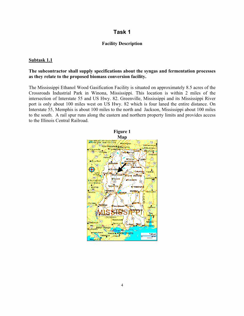
Connections are installed within the plant providing access to municipal water and wastewater disposal systems. Electrical and natural gas connections with local utilities are in place and ready for use. Process and instrument air systems are installed in the facility as are process water headers. Area lighting has been installed around the control room building and in certain process locations. Pipe racks have been built and run the length of the plant site. A fire water hydrant has been located on the west end of the site within reach of both the building and the wood reactor.
Figure 2 Existing Plant Configuration
The 30 dry ton per day (40 wet tons) wood gasification reactor was constructed with initial plans focused on the use of the gasifier as a feed for a catalytic-based methanol production process. This facility was designed to produce a synthesis gas (syngas) from waste sawdust generated by several sawmills within a short radius of the plant. However, economic events worldwide with regard to the methanol market caused the economic feasibility of the methanol venture to be considered a fruitless effort. Therefore, ME has decided to pursue the production of ethanol using fermentation. Most of the equipment pertaining to the gasification of the wood waste has already been installed. The major equipment includes a wood dryer, hammermill, baghouse collection system, wood gasification system, flue gas heat recovery equipment, process gas heat recovery equipment, and particulate removal equipment.
6
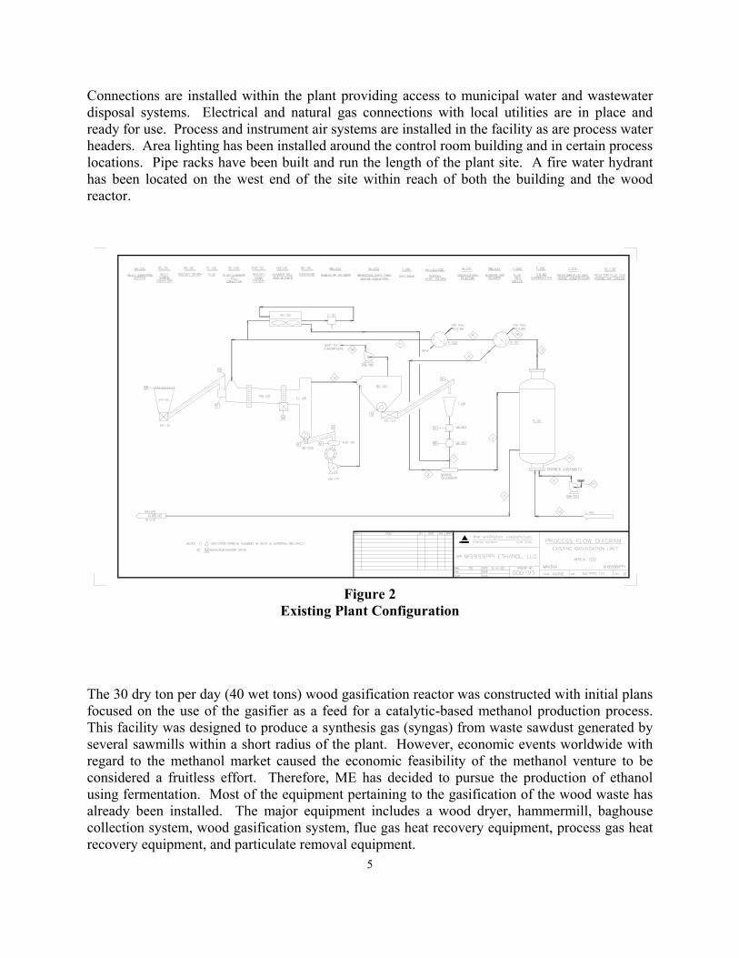
Table 1 EQUIPMENT STATUS CAPACITY / TYPE Wood gasifier
- feed system - reactor - flue gas piping - utility connections
Installed
- 30dry tons per day sawdust - various conveyors - 14 Mmbtu/hr burner
Sawdust drying/sizing system - feed system - rotary dryer - hammermill
Installed - 45 wet tons per day sawdust - various conveyors - 5’ dia. x 35’ length - 7000#/hr sawdust
Baghouse system - 144 element baghouse - induced draft blower
Installed - Polyester bags, 13000 acfm - 24000 acfm @ 5” s.p.
Flue gas heat recovery - steam superheater - steam boiler
Installed
Process gas heat recover Installed - 100 ft2 fintube Process gas particulate removal
- water wash column - ash filter
Installed - 4 tray direct contact - stainless tray filter
Flare system Installed In addition, a 30 ft x 50 ft building houses the installed control room, electrical switchgear, as well as, a shop and storage area. A detailed listing of the installed equipment can be found in the Arrington Corporation report. Modifications to the existing gasifier system will consist of the addition of a wood dryer burner system and an auxillary process boiler. The gasifier feed system will be expanded and covered. Also, the instrument and electrical systems will be modified, as necessary, to adhere to all appropriate codes and standards. Figure 2 shows the existing gasification facility. Reports have been prepared by Mississippi State University Diagnostic Instrumentation and Analysis Laboratories (DIAL) and The Arrington Corporation detailing requirements for completion of the Mississippi Ethanol gasifier system. Also, since construction on the ME facility has been idle for the past few years, the MSU DIAL report addresses inspection, testing, and repair of the existing equipment that will be utilized in the proposed biomass conversion facility. The addition of a synthesis gas to ethanol biological conversion unit will require equipment as shown below. The requirements for this unit are detailed in The Mississippi State Chemical Engineering report on biological conversion and in The Arrington Corporation report. The

7
facility capacity utilizing the existing gasification unit and with the addition of fermentation equipment is 4000 gallons per day.
Major Equipment Purchases Fermenters:
4-25,000 gallon units @$7.00 per gallon (based on two vendor estimates) = $700,000
Note: A 17 hour HRT was used for this calculation 1-2,500 gallon stock fermenter* @$7.00 per gallon = $17,500
Used for archiving a culture of pure isolates for use when the production fermenters need reseeding of the isolates due to scheduled or accidental shuts.
Membrane Biomass Separators:
4-25 gpm Zenon separators (quoted from Zenon) @ $160,000 each = $640,000
Tankage:
2-30,000 gallon holding tanks from fermenter 1-100,000 gallon ethanol storage tank 1-50,000 gallon wastewater storage tank 1-7,500 nutrient feed tank
Total Tankage - 220,000 gallons @$2/gallon (based on actual prices from a chemical plant that has recently purchased tanks) = $440,000
Waste Stream Treatment:
150,000 gpd wastewater plant @ $2/gallon (from vendor estimate) = $300,000
Air treatment (note sure so guessed this) = $200,000 Pumps:
Assuming: 4-fermenter pumps 3-chemical feed pumps 2-culture fermenter pumps 2-distillation feed pump
3-wastewater pumps 2-extra in case I missed something
Total pumps needed - 16 @ $3,000 (assumed average) = $48,000

8
Distillation/Dehydrator:
As per Cliff George (MSU-CHE) - $900,000 (rounded figure that does not include supporting equipment costs or labor because this will be included in %-based estimation estimates given below as per Peters and Timmerhause [1991]).
TOTAL EQUIPMENT ESTIMATE = $3,795,000
It is strongly suggested that a pilot-scale study be performed at the ME Site in which a small-scale fermentation pilot be constructed and operated at the site. The syngas fed into this pilot plant should be the actual syngas generated by the ME gasifier. Provisions will have to be made for managing the excess syngas or plans made for storing large quantities of syngas with the gasifier operated on an occasional basis (if feasible in terms of process stability and operations). The pilot plant should produce at least 0.5 gpd of ethanol. Sizing of the various unit processes should be based on targeted ethanol concentrations exiting the fermenters and associated cost of equipment scaled to meet the targeted ethanol production rate (i.e. >0.5 gpd Eth-OH). The total equipment cost for the pilot unit has been estimated by Mississippi State University to be $323,000. Therefore, a cost of $517,000 is suggested for the pilot system equipment which includes a 50% scaling factor composed of a 30% error margin for costing the equipment and 30% piping/fitting/electrical/yard prep cost.

9
Subtask 1.2 The subcontractor shall specify process-related requirements for the biomass conversion facility. As stated previously, the ME facility was designed to make use of sawdust generated and available nearby. The minimum feedstock requirement for this unit is 30 tons/day of wood waste at or below approximately 15 percent moisture by weight. This corresponds, roughly, to about 40 tons/day of wet, or natural, sawdust. The current design of the wood handling portion of the facility allows for use of the sawdust portion of the wood waste, sawdust. However, with relatively minor changes, the plant could use both sawdust and bark. In addition, a variety of wastes could be used depending on the availability and price. If only agricultural wastes are included, the feedstock supply for the Mississippi Ethanol facility within a small radius is tremendous. The ethanol production rate which the ME facility achieves will depend on several factors and process parameters. The current design expectations are based on studies done by Mississippi State University and included in their attached report. The biological process was modeled for the Mississippi Ethanol gasifier design values for yield and gas composition. These base values are as follows:
H2 46.6 % (mol) CO 28.0 % CO2 15.0 % CH4 7.0 % C2H4 2.0 % C6H14 0.7 % C6H6 0.7 %
Gas flow rate (dry) : 460 moles/hr Gas flow rate (wet) : 530 moles/hr
Since the ME gasifier has the ability to adjust the gas composition by varying operating parameters, this was also simulated. The results indicated an ethanol production rate of 1700 – 6000 gallons per day based on the ME gasifier design. The most probable range of values is within the 3000 – 4000 gallons ethanol per day. With literature reports of the possibility of attaining 90 percent of theoretical values, production expectations for the 30 dry ton sawdust per day have been set at 4000 gallons ethanol per day. The production of additional chemical products is highly likely and addressed in the Mississippi State report. Biomass is derived from carbon within the biosphere and, after combustion, is returned to the biosphere, therefore, the natural carbon balance is not changed. Disposal of waste biomass products is challenging the industries producing these wastes in terms of locating disposal facilities and cost (ranging from $15 - $75/ton depending on geographic location and landfill demand). The production of ethanol from these waste sources allows for the beneficial
10
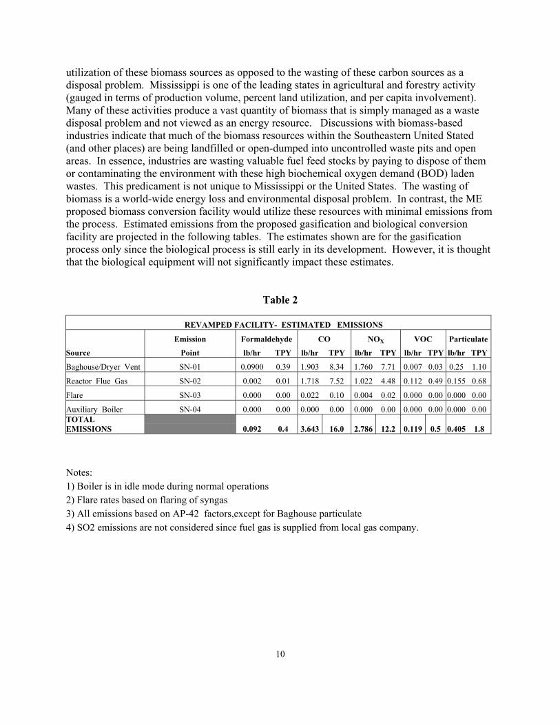
utilization of these biomass sources as opposed to the wasting of these carbon sources as a disposal problem. Mississippi is one of the leading states in agricultural and forestry activity (gauged in terms of production volume, percent land utilization, and per capita involvement). Many of these activities produce a vast quantity of biomass that is simply managed as a waste disposal problem and not viewed as an energy resource. Discussions with biomass-based industries indicate that much of the biomass resources within the Southeastern United Stated (and other places) are being landfilled or open-dumped into uncontrolled waste pits and open areas. In essence, industries are wasting valuable fuel feed stocks by paying to dispose of them or contaminating the environment with these high biochemical oxygen demand (BOD) laden wastes. This predicament is not unique to Mississippi or the United States. The wasting of biomass is a world-wide energy loss and environmental disposal problem. In contrast, the ME proposed biomass conversion facility would utilize these resources with minimal emissions from the process. Estimated emissions from the proposed gasification and biological conversion facility are projected in the following tables. The estimates shown are for the gasification process only since the biological process is still early in its development. However, it is thought that the biological equipment will not significantly impact these estimates.
Table 2
REVAMPED FACILITY- ESTIMATED EMISSIONS
Emission Formaldehyde CO NOX VOC Particulate
Source Point lb/hr TPY lb/hr TPY lb/hr TPY lb/hr TPY lb/hr TPY
Baghouse/Dryer Vent SN-01 0.0900 0.39 1.903 8.34 1.760 7.71 0.007 0.03 0.25 1.10
Reactor Flue Gas SN-02 0.002 0.01 1.718 7.52 1.022 4.48 0.112 0.49 0.155 0.68
Flare SN-03 0.000 0.00 0.022 0.10 0.004 0.02 0.000 0.00 0.000 0.00
Auxiliary Boiler SN-04 0.000 0.00 0.000 0.00 0.000 0.00 0.000 0.00 0.000 0.00 TOTAL EMISSIONS 0.092 0.4 3.643 16.0 2.786 12.2 0.119 0.5 0.405 1.8
Notes: 1) Boiler is in idle mode during normal operations 2) Flare rates based on flaring of syngas 3) All emissions based on AP-42 factors,except for Baghouse particulate 4) SO2 emissions are not considered since fuel gas is supplied from local gas company.

11
Table 3
The facility acquired a construction/operating permit dated October 26, 1993, for the methanol facility currently on-site. A copy of the permit is included in the Arrington Report Appendix. The permit expired in 1998, therefore, a new air permit must be acquired for the construction and operations of the proposed biomass conversion plant. Discussions with the Mississippi Commission on Environmental Quality indicates that the facility could probably qualify as a “synthetic minor source”. The main criteria for this classification are:
- Total emissions are < 100 TPY - Hazardous air pollutants (HAP’s) are less than 10 TPY for any single HAP and less than 25 TPY for all HAP’s on site. The anticipated duration to receive this permit, once filed, is approximately 4 months. Information that must be included in the permit application packet that deals with protecting surface water will be much simpler because Mississippi Ethanol plans to discharge its wastewater to the City of Winona sewer system. The facility will have two major requirements, aside from storm water permit issues. First, pretreatment restrictions will be placed on the wastewater discharged to the city sewer system. Plant engineering and operating conditions will need to be established that will conform to those requirements. Second, a Spill Prevention Control and Countermeasures Plan (SPCC) will need to be developed for the onsite storage of fuel oil used to power the diesel generators. In the event that storage tanks for the petroleum product are placed underground, the SPCC plan will not be required but the tanks will be subject to 40 CFR 280 Underground Storage Tank Regulations. Of the approximately 8.5 acres available at the ME site, only about 3 are currently being utilized. The remaining 5.5 acres should be adequate for the installation of the proposed biological facility. If, however, additional acreage is necessary, the site is bordered on the north and west
GRASSROOTS ESTIMATED EMISSIONS @ 30 TPD Wood Feed Emission Formaldehyde CO NOX VOC Particulate
Source Point lb/hr TPY lb/hr TPY lb/hr TPY lb/hr TPY lb/hr TPYDryer/Cyclone Vent SN-01 0.0900 0.39 2.003 8.77 1.820 7.97 0.013 0.06 0.25 1.10 Reactor Flue Gas SN-02 0.002 0.01 1.718 7.52 1.022 4.48 0.112 0.49 0.155 0.68 Auxiliary Boiler SN-03 0.000 0.00 0.206 0.90 0.122 0.53 0.013 0.06 0.019 0.08 TOTAL EMISSIONS 0.092 0.4 3.9 17.2 3.0 13.0 0.1 0.6 0.4 1.9
Notes: 1) Above emission are for the Gasification Unit only,i.e. the Ethanol Unit is not included since the processing scheme is conceptual.

12
be another 30 acres within the Industrial Park. This land has not been committed and is available for expansion as required. As discussed above, the ME facility is located in a prime location for either truck or rail transport of the products to several possible markets. Transportation of the products by truck will proceed as is normal in the movement of other chemical commodities and, as such, will require no special treatment other than standard identification and carrier licensing. Rail transport will utilize standard bulk chemical cars. Secondary transport by barge will also utilize standard industry standards in use for bulk chemical shipments. For each of the transportation options discussed above, the use of an appropriate loading system at the ME site, as well as, an unloading system at the point of delivery is understood and assumed. On-site storage of the product ethanol and any byproducts or coproducts will require closed-top tanks with overpressure protection and spill containment. Tank losses from product storage should be addressed B conservation vents, carbon bed adsorbers, and/or tank balancing. Materials of construction for the tanks should present no unusual requirements.

13
Subtask 1.3 The subcontractor shall develop capital and operating costs based on process considerations. Capital and operating costs were calculated and compiled for two cases. The first case evaluated a revamping of the existing gasification unit for operation as a feedstock supply to a biological conversion facility. Estimates were assembled by Mississippi Ethanol, Mississippi State Univ. (DIAL), and The Arrington Corporation. Table 4 shows the combined DIAL/ME capital cost estimate for the proposed revamp.
Table 4
DIAL/ME Estimated Capital Cost for the Revamped Gasification Facility
Estimated Capital Cost Cost Category dollars
Equipment 67,300
Supplies 333,987
Personnel 143,023
Contingency 200,000 Total Capital Cost $ 744,310 The total cost of $ 744,310 accounts for inspection, testing, modification, and replacement (where required) with regards to the existing wood handling, gasification, and process gas treatment systems. Additional detail is provided in the DIAL report. As noted above, The Arrington Corporation report also addresses the case of preparing the gasification unit for syngas feed to a biological conversion unit. The Arrington estimate was evaluated and adjusted as shown in Table 5 to account for items already included in the DIAL/ME total. Also, some items identified by Arrington were deemed unnecessary or outside the proposed project scope by a DIAL/ME review.

14
Table 5
Estimated Capital Cost for the Revamped Gasification Facility
Arrington Company Estimate DIAL * Adjusted Arrington Estimate
Cost Item dollars dollars Major Equipment Replace Burner System on Reactor 30,000 NA Cyclone upstream of Baghouse 15,000 NA Duct Burner System on Rotary Dryer 48,000 48,000 Auxiliary Boiler 50,000 50,000 Field Directs Instrumentation 108,000 45,000 Electrical 136,000 55,000 Other (1) 246,000 50,000 Field Indirects (2) 121,000 15,000 Construction Eng., Management, & Safety 33,000 33,000 Process & Detail Engineering 135,000 0 * Utility Power Supply 5,000 0 * Spare Parts and Supplies 40,000 NA Subtotal 967,000 296,000 Contingency 200,000 0 * If new Reactor required 350,000 NA Grand Total Capital Cost $1,517,000 $ 296,000
15
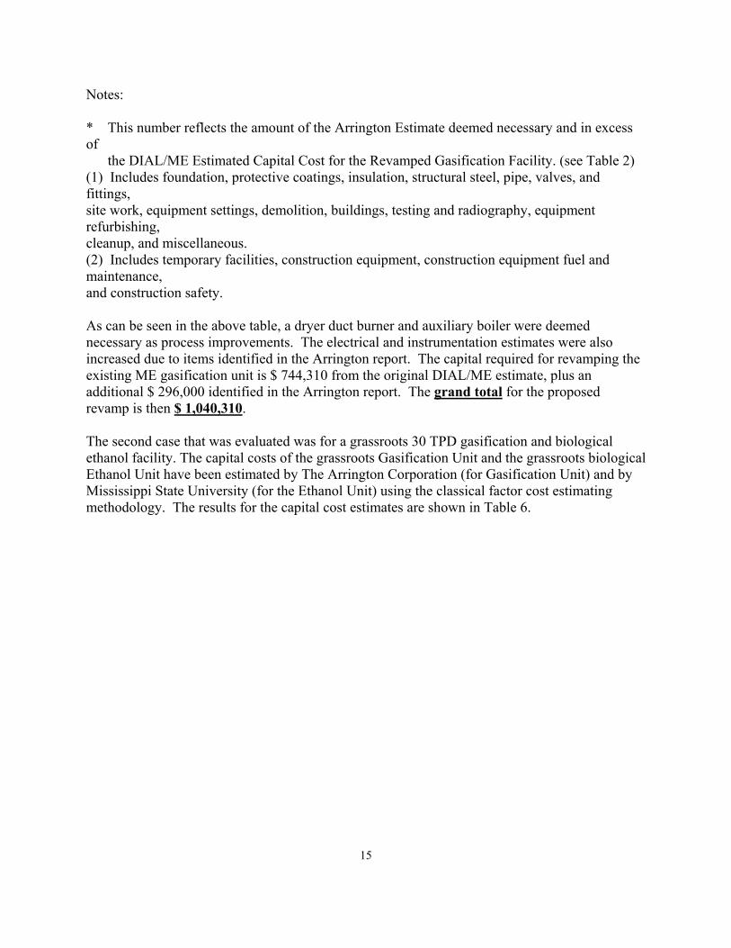
Notes: * This number reflects the amount of the Arrington Estimate deemed necessary and in excess of the DIAL/ME Estimated Capital Cost for the Revamped Gasification Facility. (see Table 2) (1) Includes foundation, protective coatings, insulation, structural steel, pipe, valves, and fittings, site work, equipment settings, demolition, buildings, testing and radiography, equipment refurbishing, cleanup, and miscellaneous. (2) Includes temporary facilities, construction equipment, construction equipment fuel and maintenance, and construction safety. As can be seen in the above table, a dryer duct burner and auxiliary boiler were deemed necessary as process improvements. The electrical and instrumentation estimates were also increased due to items identified in the Arrington report. The capital required for revamping the existing ME gasification unit is $ 744,310 from the original DIAL/ME estimate, plus an additional $ 296,000 identified in the Arrington report. The grand total for the proposed revamp is then $ 1,040,310. The second case that was evaluated was for a grassroots 30 TPD gasification and biological ethanol facility. The capital costs of the grassroots Gasification Unit and the grassroots biological Ethanol Unit have been estimated by The Arrington Corporation (for Gasification Unit) and by Mississippi State University (for the Ethanol Unit) using the classical factor cost estimating methodology. The results for the capital cost estimates are shown in Table 6.
16
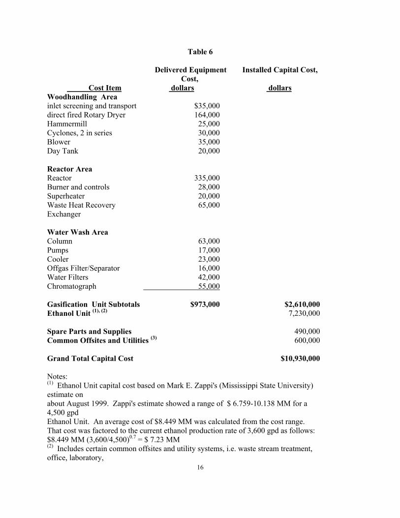
Table 6
Delivered Equipment Cost,
Installed Capital Cost,
Cost Item dollars dollars Woodhandling Area inlet screening and transport $35,000 direct fired Rotary Dryer 164,000 Hammermill 25,000 Cyclones, 2 in series 30,000 Blower 35,000 Day Tank 20,000
Reactor Area Reactor 335,000 Burner and controls 28,000 Superheater 20,000 Waste Heat Recovery Exchanger
65,000
Water Wash Area Column 63,000 Pumps 17,000 Cooler 23,000 Offgas Filter/Separator 16,000 Water Filters 42,000 Chromatograph 55,000 Gasification Unit Subtotals $973,000 $2,610,000 Ethanol Unit (1), (2) 7,230,000
Spare Parts and Supplies 490,000 Common Offsites and Utilities (3) 600,000 Grand Total Capital Cost $10,930,000
Notes: (1) Ethanol Unit capital cost based on Mark E. Zappi's (Mississippi State University) estimate on about August 1999. Zappi's estimate showed a range of $ 6.759-10.138 MM for a 4,500 gpd Ethanol Unit. An average cost of $8.449 MM was calculated from the cost range. That cost was factored to the current ethanol production rate of 3,600 gpd as follows: $8.449 MM (3,600/4,500)0.7 = $ 7.23 MM (2) Includes certain common offsites and utility systems, i.e. waste stream treatment, office, laboratory,
17
control room/motor control center room, and warehouse.
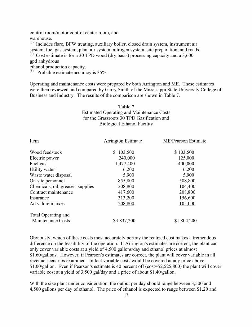
(3) Includes flare, BFW treating, auxiliary boiler, closed drain system, instrument air system, fuel gas system, plant air system, nitrogen system, site preparation, and roads. (4) Cost estimate is for a 30 TPD wood (dry basis) processing capacity and a 3,600 gpd anhydrous ethanol production capacity. (5) Probable estimate accuracy is 35%.
Operating and maintenance costs were prepared by both Arrington and ME. These estimates were then reviewed and compared by Garry Smith of the Mississippi State University College of Business and Industry. The results of the comparison are shown in Table 7.
Table 7 Estimated Operating and Maintenance Costs for the Grassroots 30 TPD Gasification and Biological Ethanol Facility Item Arrington Estimate ME/Pearson Estimate Wood feedstock $ 103,500 $ 103,500 Electric power 240,000 125,000 Fuel gas 1,477,400 400,000 Utility water 6,200 6,200 Waste water disposal 5,900 5,900 On-site personnel 855,800 588,800 Chemicals, oil, greases, supplies 208,800 104,400 Contract maintenance 417,600 208,800 Insurance 313,200 156,600 Ad valorem taxes 208,800 105,000 Total Operating and Maintenance Costs $3,837,200 $1,804,200 Obviously, which of these costs most accurately portray the realized cost makes a tremendous difference on the feasibility of the operation. If Arrington=s estimates are correct, the plant can only cover variable costs at a yield of 4,500 gallons/day and ethanol prices at almost $1.60/gallons. However, if Pearson=s estimates are correct, the plant will cover variable in all revenue scenarios examined. In fact variable costs would be covered at any price above $1.00/gallon. Even if Pearson=s estimate is 40 percent off (cost=$2,525,800) the plant will cover variable cost at a yield of 3,500 gal/day and a price of about $1.40/gallon. With the size plant under consideration, the output per day should range between 3,500 and 4,500 gallons per day of ethanol. The price of ethanol is expected to range between $1.20 and

18
$1.60 per gallon. (A short cut to estimating the price is to look at the retail price of self service, regular gasoline since the excise tax relief is about equal to the typical mark-up on gasoline). Presented below is a table of projected revenue at a production rate of 4000 gallons per day of ethanol. This model assumes the plant will operate 350 days per year. Revenue at 4,000 gal/day Yield
Price/Gallon $1.20 $1.40 $1.60
Ethanol Revenue $1,680,000 $1,960,000 $2,240,000 Acetic Acid and Other revenue 840,000 980,000 1,120,000 Total Revenue $2,520,000 $2,940,000 $3,360,000 Small Producer Tax Rebate 140,000 140,000 140,000 Total $2,660,000 $3,080,000 $3,500,000 For more detail on the economics of the proposed facility (ie, production plan, business plan, revenue projections), please refer to the Mississippi State University (College of Business and Industry) report. ** As a note, the process flow diagrams, process instrumentation diagrams, and electrical diagrams, etc.. that were generated from the various reports have been consolidated in Appendix 1. ** Appendix 2 contains a few pictures that will give a general idea of the size of the major pieces of equipment.
19
Mission and Vision of Mississippi Ethanol
Mississippi Ethanol, LLC, is a firm operating in Winona, Mississippi with the following mission:
Mississippi Ethanol will be the low-cost producer of ethanol in the Mid-South by using a biological process to convert cellulose into fuel quality ethanol and sell that alcohol to gasoline blenders in the surrounding states. Additionally, by-products such as acetates, methane, and other chemicals will be produced and either used as fuel for cogeneration of the plants= needs or sold to generate additional income.
Associated with this mission is a vision that has driven Mississippi Ethanol since its beginning and will continue to drive the firm in the future. The vision is concisely stated in the following:
Ethanol will become an increasingly important component of the fuel market in the U.S. It can extend fossil fuel, increase performance by increasing the octane by three points, and decrease air pollution. Future transportation fuels could be almost pure alcohol with vehicles already operating on 85% ethanol fuel. At the same time the disposal of waste products such as those left behind by timbering operations is a major problem. Mississippi Ethanol will take advantage of both these trends by developing a commercially viable process to convert biomass into ethanol and marketing that ethanol as an additive for gasoline and diesel. Further, Mississippi Ethanol will license the technology so that it can be used in other regions. Thus, Mississippi Ethanol will help reduce biomass wastes, air pollution from vehicles and dependence on fossil fuels. Further, these socially good activities will be done at a profit.
To fully appreciate how Mississippi Ethanol will become a successful business venture one must have some appreciation of the ethanol industry today. The next section presents a very brief history of ethanol.
Ethanol Ethanol is a product that has been around virtually as long as man. It is the result of fermenting sugars. Ethanol is the alcohol in alcoholic beverages. Ethanol has many uses. It is used in the manufacture of many products and is a key ingredient in many products. Its use as a fuel in automobiles goes back to the beginnings of the industry. Henry Ford himself worked on using ethanol as a fuel for the Model T. Germany used ethanol to extend its fuel supplies in World War II as did the U.S. and its allies. Historically ethanol has been more expensive than fossil fuel which has limited its use as a fuel to times when gasoline was in short supply. One reason for the high cost of producing ethanol is the cost of the material used to produce it.
20
The primary material used to make ethanol has been corn. The process to convert corn is simple fermentation. It is well known and produces ethanol rather efficiently. The fact that corn is the main feedstock means that most U.S. ethanol production is in the Midwest corn growing area. The largest market for ethanol has been the West, especially California. A primary reason is that California has required fuel that is less polluting for years. Ethanol acts as an oxygenate making cars burn gas more efficiently and significantly reducing air pollution. The demand for ethanol as a fuel is driven by several factors. Historically the principle driver has been the price and availability of fossil fuels. Ethanol was used as an extender of gasoline by mixing the two. Without making adjustments to the engine, vehicles will run on mixtures up to about 20 percent ethanol although 10 percent ethanol is more common. More recently ethanol demand has been driven by pollution concerns. Ethanol burns much cleaner than gasoline and when used as a 10 percent additive can significantly reduce the pollution caused by vehicles. In some especially sensitive areas such as National Parks and heavily polluted cities, vehicles that ran on pure ethanol are being tested. Vehicles running on 85 percent ethanol are being widely tested. The demand for ethanol will be discussed in greater detail later in this plan. A factor that has limited ethanol use along with its relative high cost is the fact that ethanol cannot be transported via pipelines. Ethanol will absorb water that invariably is in pipelines. Once absorbed the water adversely affects the fuel. To overcome this problem ethanol is blended nearer the consumer. Typically blenders have gasoline and ethanol in separate tanks and blend them as delivery trucks leave the terminal to take the product to service stations. Often the delivery truck takes on pure gasoline to 90 percent capacity and then add 10 percent pure ethanol to splash mix the gasohol on the way to the customer. The importance of this characteristic will become evident as this plan develops. This brief discussion of ethanol only scratches the surface of the information available on ethanol. There are literally thousands of web pages devoted to ethanol on the world wide web. It is suggested that potential investors spend some time on the web gaining and understanding of ethanol in general.
The Process Mississippi ethanol will use a process to make ethanol and related chemicals that is very different than the process used to produce most ethanol. The simplified process description is rather easily presented. Biomass is put through a thermochemical process that breaks down the cellulose into syn-gas that has sugars that are fermented by micro-organisms to produce pure ethanol and other chemicals such as acetate and methane. The feedstock is continuously fed into one end of the process and other additives are put in along the way to get the output. While this simple model aptly describes the overall process it hardly gives an understanding of the science that backs the system. The best way to think of the process is as two distinct steps. Step one is gasification of the biomass. Larry Pearson, the founder of Mississippi Methanol the precursor of Mississippi

21
Ethanol, worked for Dow Chemical in their Energy Research Group on coal gasification. In 1991, Pearson resigned from Dow to begin developing Mississippi Methanol. He spent two years designing, building, testing, and operating a prototype plant to produce synthesis gas. The prototype successfully produced syn-gas from waste products including sawdust and other wood wastes, grass clippings, straw, kenaf, bagasse, rice hulls, and others. A larger unit designed to convert forty tons of sawdust daily has been partially constructed. The other step is to introduce microorganisms to the syn-gas and through biological fermentation produce ethanol. This part of the process is still being researched. It is known that biological fermentation will work; but, the organisms that most efficiently produce ethanol are currently being determined. The fermentation portion of the process is yet to be built. There are some tremendous advantages to developing the Mississippi Ethanol plant. The advantages include:
1. Biomass is cheap and readily available. 2. The process converts biomass in a continuous flow. 3. Plants can be efficiently constructed at small scales allowing them to be built near
feedstocks and markets. 4. Many different feedstocks including some grown specifically for ethanol
production can be used. 5. The plant is safer than some ethanol plants since it operates at low temperature
and pressure. 6. The plant is environmentally sound in that it provides a way to dispose of biomass
wastes and the output helps reduce air pollution caused by automotive exhausts. 7. Other products such as acetate, butanol, and methane will be produced.
With these advantages there are a few questions. These revolve around the availability of feedstock, the demand for ethanol, and the economics of production. Each of these are discussed in greater detail below.
Feedstock Sustainability It is very easy to say that biomass is and always will be available. However, the question is whether usable biomass is and will continue to be available at a favorable cost for Mississippi Ethanol. Sawdust and other wood residues are the planned major feedstock for the plant. A 1996 study by the Food and Fiber Center at Mississippi State University projected that in 1994 a total of 12.2 million tons of wood and bark residues was generated in Mississippi. Since only larger firms were included in the survey, this figure is very conservative. The study also indicated that nearly 25 percent of the residues were not being sold. Seventy percent of the firms selling their residue indicated that they were interested in other customers. About one-third of the residue is within 100 miles of the plant site. The proposed plant will use about 40 tons of residue each day or about 15,000 tons per year. Thus, the plant will use only about one-tenth of one percent of Mississippi’s total residue. The plant would only use about one half of one percent of the unsold Mississippi residue. Even if only residue within 100 miles of the plant is

22
considered, the plant would use less than one percent of the available tonnage. With the vast majority of Mississippi’s forest being privately owned tree farms producing fast growing southern pine, there is virtually no chance of a disruption in feedstock. If for some unknown reason timber cutting were to stop, other biomass is readily available. For instance rice straw which is often burned causing significant air pollution is available in large quantities. Even if all wastes become unavailable, less than 1,000 acres of fertile Delta farm land could produce enough grass or hybrid willows to provide the feedstock needed. The cost of the feedstock will be very small. Currently the residue that is sold sells for what amounts to the cost of hauling the residue. A generous estimate of the cost is about $10 per ton delivered to the plant.
Ethanol Demand As mentioned earlier the demand for fuel quality ethanol is derived from the cost and supply of gasoline and regulations related to air pollution. Generally it costs more to produce a gallon of ethanol than a gallon of gasoline. However, to encourage alternate, renewable fuels and less polluting fuels the U.S. government currently has an incentive of about 54 cents a gallon. While this incentive is scheduled to be reduced during the next few years and expire in 2007, it means that it is economically viable to blend ethanol as long as its delivered cost is within 50 cents per gallon of the delivered wholesale cost of gasoline. Since ethanol cannot be shipped by pipeline, it is the cost of both fob blender that is germain. Some states also provide incentives to blenders. Pollution related regulations also affect the demand for ethanol. The Clean Air Act Amendments of 1990 requires the use of oxygenates in cities that exceed public health standards for ozone and carbon monoxide. Ethanol is an effective oxygenate. Other oxygenates such as MTBE are suspected of causing ground water contamination. California has mandated that the use of MTBE be eliminated by 2003. Industry sources indicate that replacing MTBE with ethanol nationally would increase demand by 2.1 billion gallons annually. The Energy Policy Act of 1992 is also increasing the use of ethanol. This act requires that government and utility/fuel provider fleets purchase alternate fuel vehicles as part of any new vehicle purchases. This mandate is largely responsible for the increase in E-85 vehicles, which are vehicles that ran on 85 percent ethanol and 15 percent gasoline. The National Park Service plans to significantly increase its use of E-85 vehicles to reduce pollution within the parks. In August of 1999, President Clinton issued an Executive Order, Developing and Promoting Biobased Products and Bioenergy. The purpose of the Order is to further the development of a comprehensive national strategy that includes research, development, and incentives to stimulate the creation and adoption of technologies needed to make biobased products and bioenergy cost competitive in national and international markets. The goal of the order is to triple the use of bioenergy and bioproducts by 2010.

23
The run-up of gasoline prices during 2000 and the increasing concern over pollution caused global warming all point toward growing demand for ethanol. Currently fuel ethanol demand is only about one percent of gasoline. It is easily conceivable of this increasing five to ten-fold in the next ten years. The inability to mix ethanol with gasoline and then ship via pipelines means that either ethanol must be produced near where it is blended or high transportation costs will have to be absorbed. There are many potential blenders close to Winona, Mississippi. Memphis is only about two hours north on Interstate 55. Other jobbers/blenders are even closer. Currently, little ethanol blended fuel is sold in the region. The simple reason is that little ethanol is produced in the region. Discussions with several potential customers revealed that, if ethanol were available at a price that is below gasoline by even a few cents, they would buy the ethanol. An interesting sub-market for Mississippi Ethanol is the farm operations in the Mississippi Delta. These farms are often thousands of acres and use thousands of gallons of fuel. Informal discussions with some indicated that they would consider blending ethanol at the farm. In general, there are strong indications that a market will exist if ethanol can be produced at a delivered price lower than gasoline.
Competition The principle competition to ethanol blended gasoline is non-blended gasoline. Certainly it is simpler for the jobbers who supply service stations with gasoline to use non-blended gasoline. They only have to get the gasoline from the nearest pipeline and transport it to the stations. If they are to use ethanol-blended product they will need a separate storage facility for the ethanol and a way to blend it. On its side ethanol increases the octane of gasoline by three points for each 10 percent of ethanol added. With most jobbers operating on rather thin margins, cost is the critical factor in this competition. Gasoline has additives that increase the octane and in some ways these are the most direct competition. Since lead was removed from gasoline, MTBE has been the most common additive. Now that there is evidence that MTBE is causing contamination of ground water, its continued use is in question. Any alternate fuel can also be considered a competitor to ethanol. Electric cars could reduce demand for both gasoline and ethanol. However, the replacement of combustion engines with electric motors in automobiles does not appear to be imminent. Fuel cells and other high tech solutions also do not appear to present strong competition in the foreseeable future. Competition for the ethanol produced by Mississippi Ethanol is also ethanol from other producers. There is no real difference in the ethanol regardless of the feedstock used. That is ethanol produced from corn is the same as ethanol produced from biomass. Ethanol is a commodity product with competition being based on price. A low-cost strategy is necessary since there is little chance to differentiate one ethanol from another. Some differentiation with Mississippi Ethanol may be possible by stressing that wastes are used as feedstock rather than corn a product that could help feed the world. Still, price will be the main competitive factor. During 2000, ethanol sold for about $1.20 to $1.30 per gallon with higher prices likely.

24
Most ethanol is produced in the Midwest corn belt. According to the Renewable Fuel Association over 90 percent of all ethanol production is concentrated in the states of Illinois, Iowa, Nebraska, Minnesota, Indiana, and Kansas. Other states are getting into production with other feedstocks such as potatoes in Idaho, brewery waste and wood in Colorado and Washington, grain sorghum in New Mexico and Nebraska. There are even two reports on the world wide web that discuss making ethanol from sawdust and other wood residue. (These can be found at: http://techlink.msu.montana.edu/ethanol.html and http://www.pyr.ec.gc.ca/ep/wet/section16.html). Plants that are located near the source of feedstock and markets generally have a competitive advantage. There are currently no plants in commercial operation that use the process planned by Mississippi Ethanol nor wood residues as the primary feedstock although there is considerable discussion of wood as a feedstock as evidenced by the above mentioned web sites. Another important consideration related to feasibility of Mississippi Ethanol relates to government programs.
Government Support Government support is necessary for ethanol to compete with gasoline. It costs more to produce ethanol with current technology than it costs to produce gasoline. Currently, there is a 54 cents per gallon exemption from excise taxes for each gallon of ethanol blended with gasoline and a 10 cents per gallon tax credit for ethanol producers who produce less than 15 million gallons a year. Essentially if a plant the size of the one planned were producing in 2000, its customers would get a tax exemption of 54 cents for each gallon of ethanol they bought from Mississippi Ethanol and Mississippi Ethanol would get a tax credit of 10 cents for each gallon of production. The tax incentives are scheduled to be decreased over the next few years. It will drop to 53 cents in 2001 and 2002, 52 cents in 2003 and 2004, and 51 cents in 2005 through 2007. The fate of the incentive after 2007 is open to question. There are strong opinions in favor of and against maintaining the incentive. Certainly unsettled conditions in the major oil producing areas, higher oil prices, and heavier dependence on foreign oil argues strongly for incentives. Another government related issue involves pollution regulations. Some, particularly oil companies, blamed the 2000 run up of gasoline prices, especially in the upper Midwest, on oxygen requirements in the Clean Air Act Amendments of 1990. For a time there appeared to be some sentiment in Congress to relax the requirements for oxygenates. While it now appears that there will be no change in the rules, it remains an extreme threat to the ethanol industry. Of course regulations could also be tightened. If MTBE is excluded as an oxygenate the demand for ethanol would likely grow three folds. To this point most of the this plan has focused more on macro issues related to ethanol and its production. Generally these macro issues lend support or point toward the success of Mississippi

25
Ethanol or at least an ethanol producer in the market area of Mississippi Ethanol. The remainder of the plan will focus more on how Mississippi Ethanol, LLC will succeed.

26
Background and History A firm called Mississippi Methanol was founded by Larry Pearson in Winona, Mississippi during 1993. This partnership was formed to produce methanol from sawdust and other wood residue through a gasification process. Pearson, who had been an engineer with Dow Chemical working in the Research and Development Department on coal gasification was able to design, build and test a small prototype that successfully converts a number of waste products into high quality synthesis gas. Mr. Pearson then raised funds from relatives and others in the Winona area to build a unit capable of converting 40 tons of sawdust a day into syn-gas. The $2.3 million raised was spent and the unit is 75% complete. It is estimated that $1,040,310 additional money is needed to make this unit operational. In November of 1999 it had become clear to Pearson that ethanol had a better future than methanol and that a different structure was needed. Therefore, Mississippi Ethanol, LLC was formed. The fermentation unit is still in the prototype development stage. It is known that there are biological organisms that will convert syn-gas into ethanol. It is believed by many that biological fermentation holds the most promise for making ethanol more competitively priced vis-a-vis gasoline. The trick is to find the specific combination of organisms and related material that produces ethanol with the greatest cost efficiency. Presently Dr. Lewis Brown, a well known researcher at Mississippi State University, is working on identifying the organism mix. Others at the University working through the Diagnostic Instrumentation and Analysis Laboratory are working on other aspects of the firm. Additionally an engineering firm has completed a study on the equipment needed to begin production.
Organization and Structure Mississippi Ethanol is organized as a limited liability company under the laws of the state of Mississippi. This form of ownership allows a firm to have most of the advantages of a corporation while being treated more like a partnership for tax purposes. It is considered by many to be the best form of ownership for a start up entrepreneurial firm. Larry Pearson has been the driving force in the establishment of Mississippi Ethanol and will continue to lead the organization. Being a leading edge firm from a technology perspective requires that Mississippi Ethanol, LLC maintain its closeness to the research community. Mississippi State University has the science and engineering expertise to help Mississippi Ethanol, LLC stay at the edge. This relationship will be maintained through agreements between Mississippi Ethanol, LLC and University units as well as advisory relationships with individual relationships.

27
The planned organization structure is as follows: Maintaining this lean structure is important to the success of Mississippi Ethanol, LLC. In the beginning Larry Pearson will provide overall administration as well as handling the marketing activities. It is envisioned that a limited number of buyers will purchase the entire output of the plant. When the plant is expanded or other units are added a full-time marketing person will be hired. Since the plant will be a continuous production facility, three shifts of production workers are needed. It is envisioned that about two production workers and one maintenance worker will be needed on each shift. The continuous process will require four shifts. Additionally one person will be designated as the plant manager. Plans for the functional areas of the firm are presented next.
Production Plan Mississippi Ethanol must be able to produce ethanol that can be priced at or below the wholesale price of gasoline after consideration of the excise tax exclusion of about 50 cents per gallon. Also, for long term survival it must be able to produce ethanol at a price comparable to ethanol produced from corn. Mississippi Ethanol has one huge advantage and one possible disadvantage. The feedstock (wood residue) for Mississippi Ethanol is a small fraction of the price of corn. Wood residue in the area of the plant can be purchased for a delivered price of about $10 per ton. Corn which has much more volatile prices can cost that much for 100 pounds. Even when looking at a worse case scenario of $20 per ton for wood residue and below normal corn prices there is no comparison. The problem is that Mississippi Ethanol must also buy microorganisms and their nutrients. These must be considered as part of feedstock. Since the organism/nutrient Asoup@ is still be researched, a price estimate is not possible. However, it is believed that the combined cost of the wood residue and the soup will be significantly less than the cost of corn needed to produce a gallon of ethanol. Wood based ethanol will also require a greater investment in plant and equipment. Corn based ethanol requires only direct fermentation. Wood residue must be gasified first. However, an important plus for wood residue ethanol is that smaller plants such as the one planned can be used. Transportation costs also enter into the production plan. A bulky raw material is converted into a liquid. Generally it is better to build plants closer to the material in this situation. Indeed most ethanol production facilities are located near the feedstock, corn. The transportation cost for ethanol via tanker can be high. The plant in this plant will produce about 4,000 gallons per day. This amount can be absorbed easily with 200 miles of the Winona location. The plant is located within 2 miles of the intersection of Interstate 55 and US Hwy. 82. Greenville, Mississippi and
28
its Mississippi River port is only about 100 miles west on US Hwy. 82 which is four laned the entire distance. On Interstate 55, Memphis is about 100 miles to the north and Jackson, Mississippi about 100 miles to the south. Should the plant be expanded in the future, there is a railroad spur on the property and river terminals are available at both Greenville and Memphis. Even the giant petrochemical plants of Baton Rouge and New Orleans are only about 250 Interstate Highway miles south of the site. These markets can also absorb the by-products of the process. Some of the power for the plant will be co-generated. Methane can be drawn from the gasification process to power generators and provide the boiler fuel needed. As stated previously, the process that Mississippi Ethanol will use can be feasible at small scale. This is important because part of long term plan is to build other plants or license the technology to others. The ability to use a variety of wastes means that small scale plants like the Winona plant can be built near both material and market. For instance agricultural wastes such as rice straw, cotton stalks, vegetable trimmings, etc. in California could be used to supply some of the high demand without incurring cross country transportation costs.
Marketing Plan The marketing strategy flows directly from the production strategy. That is, sell the ethanol at an effective price enough under gasoline for jobbers/blenders within 200 miles of Winona, Mississippi to begin blending gasohol. Currently there is very little blended gasoline sold in this market area. The reasons are quite simple: 1) there are no regulations requiring ethanol, 2) there has been no effort to produce or sell ethanol in the area. Discussions with one jobber revealed that, if ethanol were available at a price which would allow him a few pennies a gallon more profit, he would blend. Others expressed similar ideas. Since most jobbers only make a profit of a few cents a gallon, they are very susceptible to any innovation that make them even an extra penny a gallon. If ethanol can be profitable sold at an effective price (delivered price minus the excise tax incentive of about 50 cents per gallon) 10 cents below the delivered wholesale price of gasoline, the blender will make 1 cent more per gallon. If the ethanol could be sold at an effective savings of 25 cents per gallon, most jobbers would almost double their net profit. At this price level ethanol demand would be very, very good. The analysis is complicated because of ethanol’s ability to improve octane rating. Eighty-four octane gasoline becomes eighty-seven octane when mixed with 10 percent ethanol. Thus, jobbers/blenders would actually have to compare the price of regular gasoline (87 octane) with intermediate gasoline (89 octane). Another potential market is the farming community of the Mississippi Delta. Operations of 20,000 acres are not uncommon. Many of these farms buy bulk fuel and most have a shop capable of making any needed adjustments to burn blended fuel. Fuel is a major cost for the intensive methods of cultivation practiced in the Delta. The plant site is on the eastern edge of the Delta.

29
Licensing of the technology may actually make more money for Mississippi Ethanol than ethanol production at the plant. Pearson has patents pending on parts of the gasification process. Patents will be applied for on the fermentation process. Mississippi Ethanol will control at least part of these patents. If the process performs as efficiently as projected the license to use the technology will be valuable. Although this plan focuses on the production and sale of ethanol at the proposed plant, the potential for license sales must be factored into the profit equation.
Financial Projections As with any new process technology, financial projections are extremely difficult to make for Mississippi Ethanol. On the revenue side plant output and price are difficult to predict. Even more difficulties exist on the cost side. Arrington’s report is believed to be a Aworst case@ cost estimate. Larry Pearson estimates significant lower costs. With the unsettled nature of the financial, we will present here a simple analysis with different assumptions and draw conclusions based on those various assumptions. Revenue The revenue generated by Mississippi Ethanol will be determined by the quantity of ethanol and other chemicals produced and the price of those chemicals. The two main saleable outputs of Mississippi Ethanol will be ethanol and acetic acid. Generally acetic acid sells for about twice the price of ethanol; however, acetic acid production will be less than ethanol. We have assumed that acetic acid will generate total sales of about half that of ethanol. With the size plant under consideration, the output per day should range between 3,500 and 4,500 gallons per day of ethanol. The price of ethanol is expected to range between $1.20 and $1.60 per gallon. (A short cut to estimating the price is to look at the retail price of self service, regular gasoline since the excise tax relief is about equal to the typical mark-up on gasoline). Presented below are tables of projected revenue with different price/output assumptions. All models assume the plant will operate 350 days per year.

30
Revenue at 3,500 gal/day Yield
1.20 1.40 1.60
Ethanol Revenue 1,470,000 1,715,000 1,960,000
Acetic Acid and Other Revenue
735,000
857,500
980,000
Total Revenue $2,205,000 $2,572,000 $2,940,000
Small Producer Tax Rebate
125,000
125,000
125,000
Total $2,330,000 $2,697,500 $3,065,000
Revenue at 4,000 gal/day Yield
1.20 1.40 1.60
Ethanol Revenue 1,680,000 1,960,000 2,240,000
Acetic Acid and Other Revenue
840,000
980,000
1,120,000
Total Revenue $2,520,000 $2,940,000 $3,60,000
Small Producer Tax Rebate
140,000
140,000
140,000
Total $2,660,000 $3,080,000 $3,500,000
Revenue at 4,500 gal/day Yield 1.20 1.40 1.60
Ethanol Revenue 1,890,000 2,205,000 2,520,000
Acetic Acid and Other Revenue
945,000
1,102,500
1,260,000
Total Revenue $2,835,000 $3,307,500 $3,780,000
Small Producer Tax Rebate
157,500
157,500
157,500
Total $2,992,500 $3,465,000 $3,937,500 The above information indicated that the plant can expect revenues approaching $4 million per year in the optimistic state and below $2.5 million in the pessimistic state. The other part of the profit equation is cost. Various cost scenarios are presented below.
31
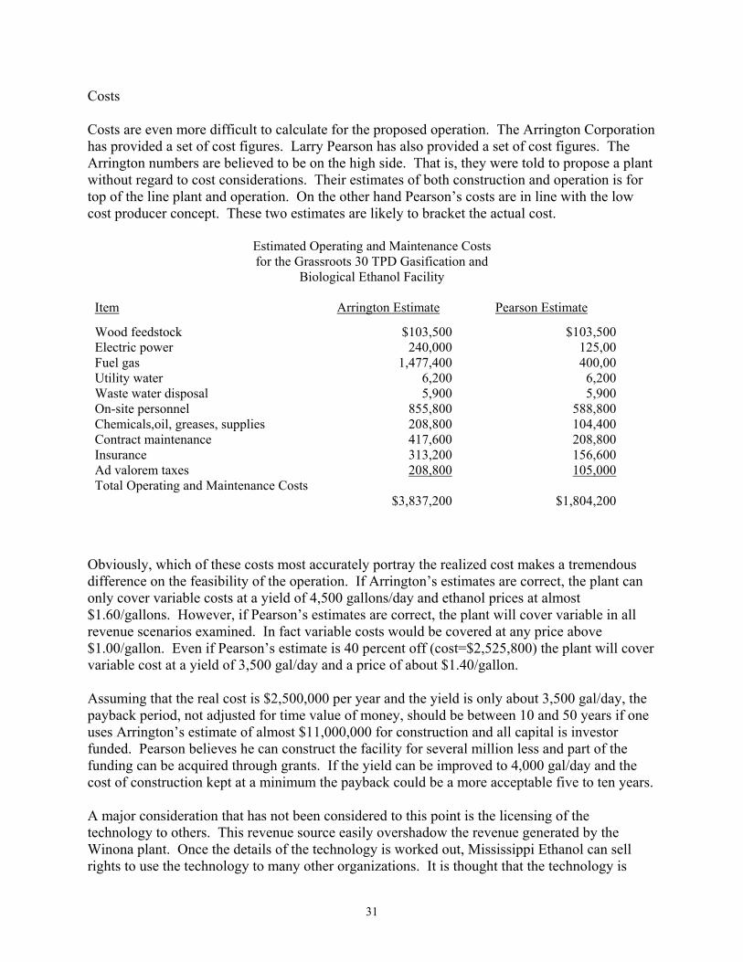
Costs Costs are even more difficult to calculate for the proposed operation. The Arrington Corporation has provided a set of cost figures. Larry Pearson has also provided a set of cost figures. The Arrington numbers are believed to be on the high side. That is, they were told to propose a plant without regard to cost considerations. Their estimates of both construction and operation is for top of the line plant and operation. On the other hand Pearson’s costs are in line with the low cost producer concept. These two estimates are likely to bracket the actual cost.
Estimated Operating and Maintenance Costs for the Grassroots 30 TPD Gasification and
Biological Ethanol Facility
Item Arrington Estimate Pearson Estimate
Wood feedstock Electric power Fuel gas Utility water Waste water disposal On-site personnel Chemicals,oil, greases, supplies Contract maintenance Insurance Ad valorem taxes Total Operating and Maintenance Costs
$103,500 240,000
1,477,400 6,200 5,900
855,800 208,800 417,600 313,200 208,800
$3,837,200
$103,500 125,00 400,00
6,200 5,900
588,800 104,400 208,800 156,600 105,000
$1,804,200
Obviously, which of these costs most accurately portray the realized cost makes a tremendous difference on the feasibility of the operation. If Arrington’s estimates are correct, the plant can only cover variable costs at a yield of 4,500 gallons/day and ethanol prices at almost $1.60/gallons. However, if Pearson’s estimates are correct, the plant will cover variable in all revenue scenarios examined. In fact variable costs would be covered at any price above $1.00/gallon. Even if Pearson’s estimate is 40 percent off (cost=$2,525,800) the plant will cover variable cost at a yield of 3,500 gal/day and a price of about $1.40/gallon. Assuming that the real cost is $2,500,000 per year and the yield is only about 3,500 gal/day, the payback period, not adjusted for time value of money, should be between 10 and 50 years if one uses Arrington’s estimate of almost $11,000,000 for construction and all capital is investor funded. Pearson believes he can construct the facility for several million less and part of the funding can be acquired through grants. If the yield can be improved to 4,000 gal/day and the cost of construction kept at a minimum the payback could be a more acceptable five to ten years. A major consideration that has not been considered to this point is the licensing of the technology to others. This revenue source easily overshadow the revenue generated by the Winona plant. Once the details of the technology is worked out, Mississippi Ethanol can sell rights to use the technology to many other organizations. It is thought that the technology is
32
scalable to both higher and lower production rates. If it is scalable to higher outputs, major refiners and marketers of fuel may well be interested in a licensing arrangement. If scalable to lower output, any firm with high fuel costs such as trucking companies or others with major vehicle fleets may find it advantageous to build their own limited production units. When one remembers all the different potential feedstocks, the possibilities become huge. There is no real way to estimate the potential revenues from licensing until the Winona plant is in operation. However, if the Winona plant can just break even, it is thought that this revenue source will be several million dollars per year. In essence, the Winona plant is needed to prove the viability of the process and it might be able to pay for itself opening they way for exceptional profits for Mississippi Ethanol, LLC., via the licensing route.

33
Final Report
From the
Diagnostic Instrumentation & Analysis Laboratory
To
Mississippi Ethanol, LLC
In compliance with the subcontract issued from Mississippi Ethanol, LLC to Mississippi State University under subcontract XC0-0-30036-01 under Prime Contract No. DE-AC36-99GO10337.
December 15, 2000

34
Mississippi Ethanol Dial personnel visited the Mississippi Ethanol Plant in Winona, Ms several times in order to gather information about the intended operation, layout, and condition of the plant equipment. Since the plant has not been in operation for several years, there are a number of maintenance items that need attention. There has been some vandalism, which has resulted in the destruction of some small items, mainly broken glass on meters, but replacing these items will result in only minor expense. The majority of items that are in need of repair, replacement, or testing and verification are the result of lying idle for an extended period of time. Only one modification of the existing structure of the plant is recommended. The feed tank and rotary air locks, which feed the gasifier, need to be raised to a higher level in order to help prevent clogging of the feed line. At present the dried and sized sawdust is fed from near ground level to the top of the reaction vessel inside a pipe. Raising this part of the process would allow the sawdust to be conveyed to the higher level, using a belt or auger type conveyor, where it could be fed horizontally to the reactor. It is believed that this modification would significantly improve the reliability of the over all process. The following list contains general deficiencies and recommendations that resulted from plant surveys. (Table BR-549 contains maintenance and/or replacement recommendations that are specific to individual items and systems.) (1) Relocation of the rotary metering valve and the reduction in size or the elimination of the
feed hopper, giving the ability to relocate the pressure sealing rotary valve to a higher height before entering Reactor. The current stand will have to be modified (reconstructed) and an over hang or shelter should be integrated for the protection of the feed material. The plumbing will have to be redone to the pressure sealing rotary valve. Welding and plumbing will be performed and a crane will be needed.
(1) Check wiring codes for hazardous areas. ( hydrogen ) (2) Paint and insulate hot piping (approximately 500 feet) (3) Approximately 100 gallons of paint will be need for protection from the
elements. (4) High-pressure lines need hydrostatic testing. (5) Check water/steam lines for cracks or breaks due to freezing. (6) Hydrostatic test the Bryan and flue gas boiler for integrity. (7) Establish a (Leak Check Plan) (8) Add twelve or more flow, temperature and pressure measurements.

35
(9) Add a boiler feed water injection system (tank & plumbing) with blow down.
(10) Add lighting for safe nighttime operation. (11) Add safety showers near potentially hazardous areas. (12) Mark and color-code piping for flow direction and contents. (13) Start up and shut down procedures need to be written for all the equipment (14) Maintenance scheduling needs to be established for all equipment. (15) Install holding tank for wastewater that can be filtered by trash and carbon
filters before being sent to city drain. (16) Check on requirements for fire hydrants (possible one or more locations.) (17) Fence to secure area around plant. (18) Road and dirt work for the arrival of semi trucks. (19) Concrete pad for storage of wood chips. (20) Loading dock for feed hopper. (21) Air-conditioning (heating and cooling) for control area needs to be
checked. (22) Grounds need to be mowed and maintained
Table XX---Equipment Maintenance/Replacement Requirements
Equipment Components Power Requirements Work Required
1 Feed Hopper (1a) grid shaker motor
Power 110 ( M55) 110 power needs to be applied and motor checked out.
(1b) grid Shaker grid needs to be operated after checking and greasing bearings and moving components.
2 Screw Conveyer
between Feed Hopper and Rotary Dryer
Motor and reduction gear
3 phase 480 volts
(M33) Check fluid level in reduction gear and check belt or chain drive.
3 Rotary Dryer (3a) Motor for screw
conveyer through dryer
3 phase 480 volts
(M44) Check fluid level in reduction gear and check belt or chain and install cover

36
dryer cover.
(3b) Motor and reduction gear that
rotates dryer
15 hp 3 phase 480 volts
(M37) Check fluid level in reduction gear and grease moving components; construct guard around entire mechanism.
Centering Mechanism
Check bearings and grease moving components and check seal going to Particle Sizer/Separator.
4 Particle Sizer/ Separator replace component (Plexiglas) and
clean Motor for screw
conveyer in Particle Sizer/Separator
1 hp single phase 110
(M40) Check oil level in gear box
5 Screw Conveyor from
Particle Sizer/ Separator to Hammer
Mill
Motor and reduction gear
3 hp single phase 220
(M39) Reduction gear check oil level and belts or chains 15.35:1 ratio.
6 Rotary feed valve to Hammer Mill 1/2 hp single
phase gear motor 58:1
ratio
(M38) Check oil level
7 Hammer Mill/Blower 50 hp 3 phase
480 (M36) Check bearings and alignment,
clean and check screens, and inspect hammers.
8 Starter control for Hammer Mill (M36) Needs work or replacement
9 Bag House screw conveyor
variable drive 3 hp 3 phase (M34) Check push button start, check oil
level in reduction gear, remove, clean or replace bags (144 bags), needs 24 channel electronic sequencer with 1/4" solenoid valves for bag back flow system. Install sprinkler system for fires. Install differential pressure monitoring system.( 0-40" of water)

37
10 Screw conveyor to rotary feed valve
hopper
15.35:1 reduction gear (dodge belt
drive).
1 hp 3 phase (M41) Check fluid level in reduction gear and check belt or chain drive.
11 Metering Rotary valve
from rotary feed hopper to pressurized
rotary feed valve
gear reduction motor 56.75:1
1/2 hp 3 phase (M42) Check fluid level in reduction gearand check belt or chain drive.
12 Pressurized Rotary
feed valve gear motor 39.45:1 2 hp (M43) Lubricate chain and check oil
level. Disassemble completely and check tolerances.
13 Reactor Check out operation of burner
system, inspect condition of refractory lining and install 3 Temperature transmitters
Field Mounted Control Box Needs to be checked and repaired (lights, buttons and switches)
14 R2 Tank Check absolute temperatures
transmitter 15 R3 Tank Check absolute temperature
transmitter 16 Heat Exchanger (waste heat recovery) Install temperature measurement
transmitters.
17 Water Wash Column Check out instruments. Inspect and clean traps in large sparkler filter (50/60 gpm). Clean traps in water wash column (need crane for this.)
1 pump 71/2 hp 3 phase
(M46) Needs belts
2 pumps 71/2 hp 3 phase
M3 & M4
18 Water Knockout Pot Redo 6" pipe to flare
19 Flare Knockout Pot Add level measurement and drain
valve (analyze water and determine what to do with it.)

38
20 Flare Pilot System Check out or install new (flare control)
21 Seal gas compressor
for rotary sealing valve
Pulls flue gas from boiler, compresses and cools and seals
rotary valve.
(M56) Hydrostatic testing of lines from compressor to valve.
22 Super Heater Insulate, cover and check
temperature and pressure monitoring.
23 Flue gas boiler Check insulation and repair cover.
Check water level indicator, temperature and pressure gauge.
M1 and M2 pumps supply water to heat exchanger.
Need level indicator and pressure gauge on tank. Need level indicator on supply tanks to M1 and M2.
24 Pressure control of boiler to steam header Check out pneumatic valves and
gauges 25 Flow control from steam header to super heater Check out pneumatic valves and
gauges. Check out vortex steam flow meter
26 2 Screw Compressors Need buttons, gauges, and
switches replaced; oil and filters need to be changed and system needs to be tested for leaks.
27 Air Dryer Needs gauges, wiring and
switches replaced and possibly needs desiccant.
Modifications
The Engineering Study Report done by the Arrington Corporation was reviewed in light of the needs for producing a demonstration plant for making methanol. We wanted to insure that we had not missed any item that was necessary for making the plant operational. As a result of this review, we found some areas of disagreement with the “Required Modifications” presented in the report. This is not intended to indicate an error by the Arrington Corporation; it simply indicates a difference in testing philosophy. We view the plant as being a tool for demonstrating

39
the viability of the ethanol production process. The plant should be brought into operation in the most cost effect way possible as long as test results, environmental concerns, and safety are not compromised. The following list indicates the items where our ideas differ from those of the Arrington Engineering Study Report. 6.2 Required Modifications
1. Move existing Reactor south of existing Baghouse to comply with area electrical classification standards.
This is viewed as unnecessary.
2. Disconnect and remove from the process area: E-101, Steam Superheater E-102, Flue Gas Boiler C-101, Reactor Flue Gas Purge Compressor AC-102, Reactor Flue Gas Purge Air Cooler AX-201, Auxiliary Boiler This appears to be a result of moving the reactor and is not
necessary. 3. Install stack on Reactor and vent to atmosphere. 4. Replace existing burner system on the reactor with a natural draft burner system capable of
delivering approximately 20.0 MM btu/hr. There is a discrepancy between the estimation of the btu requirements by the engineering
company and the MME estimate for this process. Since the burner already installed is 15.00 MM btu/hr, it would be more practical to use it to start with and thereby determine the actual requirement be experiment.
5. Disconnect and remove from the process area the Post Reaction Vessels, V-101 and V-102. Equivalent residence time will be provided in the piping between the new location of the reactor and the Water Wash Column.
This not necessary
6. Install a cyclone upstream of the Baghouse to unload solids contacting the bags. Replace existing bags with bags constructed of Gore-Tex.
Although the cyclone is not necessary, the baghouse bags do need to be replaced with ones made of Gore-Tex.
7. Install a duct burner system with secondary air controls to maintain a flue gas temperature of 350oF to the Rotary Dryer.
8. Install a new auxiliary Boiler rated at 2,500lb/hr of 100psig steam, equipped with an
economizer to deliver steam superheated to 600oF to the Reactor.

40
9. Install variable frequency drive units (VFD’s) on all screw conveyors and metering
valves to the Reactor. Some of these already have VFD’s. Install additional ones as necessary.
10. Inspect, dismantle and reassemble as necessary, lubricate all existing equipment, valves
and instrumentation, which will be utilized.
11. Inspect all equipment items from a mechanical point of view. I.e. metallurgy. Stress analysis, design, and safety considerations.
12. Review insulation and refractory requirements and modify as required.
13. Install a new PLC operating (system) with Wonderware type software.
14. Remove electrical generators from area.
This is unnecessary.
15. Rewire all power and instrumentation from end device to control room. Rewire as necessary.
16. Bring in 480 volt, 3 phase, 60 hertz power supply from the local utility company.
17. Replace all cable tray. Replace cable trays as necessary.
18. Install plant electrical grounding system.
19. Install new instrumentation including GC as discussed in section 5.6. It is not necessary to replace all of the current instrumentation.
20. Install/modify ladders and platforms in accordance with OSHA requirements.
21. Install new pipe racks.
Install new pipe racks as necessary.
22. Install lined surface pond for waste water collection.
23. Install new dry tank for dry/milled sawdust.
24. There is a possibility that the existing Reactor will need to be replaced due to metallurgy, insulation, or other design limitations. This can only be known after a detailed engineering analysis of the Reactor has been performed.

41
Environmental
Environmental considerations for the Mississippi Ethanol facility can be divided into two categories: (1) compliance with environmental regulations and (2) assessment of the environmental impact of the alternative use of wood wastes as a raw material for the process. Compliance with Environmental Regulations The facility that will be operated by Mississippi Ethanol will, at a minimum, be subject to environmental regulations governing air pollution control and discharge of pollutants to surface water. Operating permits will need to be secured from the Mississippi Department of Environmental Quality (MDEQ) that address each of these areas of concern. It is also likely that the facility will need to notify MDEQ of its activity as a generator of hazardous wastes. Further, it will be subject to the requirements of the Community Right To Know Act and must comply with reporting requirements to the Mississippi Emergency Response Commission, the Montgomery County Local Emergency Planning Committee, and the Winona Fire Department. The most significant of the requirements listed in the above paragraph have to do with securing operating permits. The State of Mississippi has followed the national trend of issuing a single multi-media permit to a facility. The permit that the Mississippi Ethanol facility will pursue will largely address air emissions. It is unlikely that the facility will be large enough to be regulated as a major source under Title V of the Clean Air Act, so it will be regulated as a new stationary source under Section 111 (Mississippi Regulation APC-S-1). Information that must be included in the permit application packet that deals with protecting surface water will be much simpler because Mississippi Ethanol plans to discharge its wastewater to the City of Winona sewer system. The facility will have two major requirements; aside from storm water permit issues. First, pretreatment restrictions will be placed on the wastewater discharged to the city sewer system. Plant engineering and operating conditions will need to be established that will conform to those requirements. Second, a Spill Prevention Control and Countermeasures Plan (SPCC) will need to be developed for the onsite storage of fuel oil used to power the diesel generators. In the event that storage tanks for the petroleum product are placed underground, the SPCC plan will not be required but the tanks will be subject to 40 CFR 280 Underground Storage Tank Regulations. A final comment needs to be made concerning the use of diesel generators at this site. There has been considerable concern building over the levels of emission of dioxins and furans from diesel engines. An assessment of the emission rate of dioxins and furans from these units should be considered. The most effective remedy for this source of risk is to connect the facility to the local power grid and dispose of the diesel generators. This has an added benefit of avoiding the potential for spills or other releases of diesel fuel to the environment and does away with the requirement for a SPCC plan.
42
Environmental Impact Wood wastes produced in the southeastern United States have found several beneficial uses, however, a significant amount ends up being sent to a landfill each year. The old practice of allowing these wastes to be stored on-site in piles is no longer acceptable because of the potential for runoff to adversely impact surface water and the potential for fires that can smolder for years. Consequently, large amounts of wood wastes are placed into solid waste landfills each year. The extent to which wood wastes are available for use in processes has both economic and environmental consequences. Obviously, use of wood wastes as a fuel source will conserve landfill space, however, other impacts of the process must also be considered. The gasification of wood wastes to produce gases for bio-generation of either liquid fuels or commercial chemicals should be evaluated to determine the overall environmental impact of this process. This should include characterization of: (1) the stack gases and fugitive air emissions of this process, (2) process wastewater, (3) ash and solid wastes generated by the process, and (4) any other wastes produced by facility activities such as maintenance. An overall environmental impact of the process needs to be balanced against the impact of alternative disposal/uses of the material. Health and Safety Considerations Health and safety considerations for this facility will largely involve development and implementation of administrative work control systems and the training of employees. Numerous OSHA standards will be applicable to this site, either while it is being completed or during its operation. It is not clear how much of the construction and pre-startup work will be carried out by Mississippi Ethanol employees, so a relative comprehensive listing of applicable standards has been assembled.
• Employee emergency plans and fire prevention plans – required by OSHA 29
CFR Part 1910.38
• Hazardous waste operations and emergency response – required by OSHA 29
CFR Part 1910.120
• Hazard communications – required by OSHA 29 CFR Part 1910.1200
• Hearing protection – required by OSHA 29 CFR Part 1910.95
• Permit required confined spaces – required by OSHA 29 CFR Part(s)
1910.146
• Bloodborne Pathogens – required by OSHA 29 CFR 1910.1030
• Respiratory Protection – required by OSHA 29 CFR 1919.134
• Forklift Safety – required by OSHA 29 CFR 1910.178
43
• Blinding training – required by OSHA 29 CFR 1910.120
• Carcinogen training – required by OSHA 29 CFR Part 1910.1001
• Excavating and trenching – required by OSHA 29 CFR Part 1926.651
• Fire and safety work permit – required by OSHA 29 CFR Part 1910.252
• Fire brigades – required by OSHA 29 CFR Part 1910.156
• Ergonomics – required by OHSA 29 CFR 1910.900
• First Aid/CPR – required by OSHA 29 CFR Part 1910.151
• Hazardous materials and protection in workplace – required by OSHA 29
CFR Part 1910 subpart Z
• Lockout/tagout – required by OSHA 29 CFR Part 1910.147
• Personal protective equipment – required by OSHA 29 CFR Part 1910.120
and OSHA 29 CFR Part 1910.132
• Portable fire extinguisher – required by OSHA 29 CFR 1910.157
• Respiratory protection – required by OSHA 29 CFR 1910.134
• Site security – required by OSHA 30 Part 221
• Tagging and flagging – required by OSHA 29 CFR 1910.145
• Flammable and combustible liquids – required by OSHA 29 CFR 1910.106
• Employee alarm systems – required by OSHA 29 CFR 1910.165
• Electrical training – required by OSHA 29 CFR 1910.332
• Occupational exposure to hazardous chemicals in laboratories – required by
OSHA 29 CFR 1910.1450
The size of the Mississippi Ethanol plant is such that it will not be subject to the OSHA Process Safety Management Standard (29 CFR 1910.119). However, this standard is very useful as a checklist of safety management considerations that should be taken into account. This is particularly true for the start up phase of the facility. The Department of Energy is acutely aware of the frequent lack of attention paid to worker health and safety issues during the development of new environmental remediation technologies. A project that was jointly sponsored by DOE, the Southern States Energy Board, and the national Environmental Education and Training Center was initiated in 1997 to establish guidance for systematic evaluation of the occupational safety and health hazards associated with these new technologies. Interim Final Guidelines were published March 31, 1999 and are to be used by

44
developers of new technologies and supplied to those that would employ the technology. In the event that DOE provides additional funding for further development of this technology, it is recommended that these guidelines be employed in the establishment of protective programs and the targeting of training for workers to facilitate the safe transfer of the technology to other sites.

45
AN ASSESSMENT OF FERMENTATION RELATED ISSUES AT THE MISSISSIPPI ETHANOL INC.
FACILITY, WINONA, MISSISSIPPI
by
Mark E. Zappi, Clifford George, and Atly Jefcoat Dave C. Swalm School of Chemical Engineering
Mississippi State University
Lewis Brown, Jeremy Alley, and Todd French Department of Biological Sciences
Mississippi State University
Rakesh Bajpai Department of Chemical Engineering
University of Missouri-Columbia
FOR
MISSISSIPPI ETHANOL INC. WINONA, MISSISSIPPI
December, 2000

1
TABLE CONTENTS CHAPTER PAGE I. INTRODUCTION 2 II. PRODUCTION OF ETHANOL 5 III. PRODUCTION OF ETHANOL FROM SYNTHESIS 11 GAS FERMENTATION IV. UPDATE ON ON-GOING LABORATORY ACTIVITIES WITH BACTERIAL ISOLATES 30 V. SEPARATIONS CONSIDERATIONS 36 VI. FERMENTER CONSIDERATIONS 44 VII. POTENTIAL CHEMICAL PRODUCTS THAT MAY BE PRODUCED BY THE PROPOSED PLANT 55 VIII. ENVIRONMENTAL IMPLICATIONS OF ETHANOL USE AS AN ALTERNATIVE FUEL 62 IX. REVIEW OF ARRINGTON ENGINEERING REPORT 64 X. REFERENCES 65

2
Chapter I. Introduction
The earth contains a wide variety of carbon reservoirs that can be harnessed to meet the societal power requirements in the form of gaseous, liquid, and solid fuels with liquid fuels being of most importance. The modern world has come to rely almost exclusively on fossil-based reserves, a non-renewable resource, for production of liquid fuels. However, the cost and politics of being totally dependent on these reserves is getting progressively more expensive from both a strategic and sociological standpoint (Worden et al. 1991; Ingram et al. 1999). A renewable source of fuels is required for meeting the future energy needs of the United States and the world. Unfortunately, politics and policy tend to be crisis management oriented resulting in a lag in the development of alternative fuels. One potential boost to the development of alternative fuels is the recent Executive Order released in August 12, 1999 (Office of the President 1999) which directs the Secretaries of Agriculture, Energy, and Treasury and the USEPA Administrator to initiate new research and stimulate industrial efforts on the development of biomass-based alternative fuels. Recently, Mississippi Ethanol Inc. (ME) has completed construction of an innovative gasifier system for the potential conversion of wood and plant-based wastes (i.e. sawdust, ginning trash, etc.) into commercial chemicals, such as ethanol. This patent-pending design is highlighted by the capability to cost-effectively produce synthesis gas within a small-scale framework of both size and operation. The design developed by ME engineer, Mr. Larry Pearson, was proven viable through the construction and operation of a pilot scale gasifier system during 1993 - 1995 at the ME property, which is located in Winona, MS. The pilot scale test results proved that the ME design was indeed both operationally safe and technically effective in the production of a high quality synthesis gas that generally was composed of the following composition (ME Inc., 1999): 51% Hydrogen 27% Carbon Monoxide 15% Carbon Dioxide 7% Methane

3
It is also important to note that test results indicated a high potential for adjusting the compositional percentages of each of the chemicals listed above (generally balancing approximately 50% of any one inorganic constituent). It is also important note that several low levels of various other organics were detected within the syngas (discussed later in more detail). This flexibility in terms of syngas composition is very important when configuring the gasifier to compliment a potential fermentation system for production of ethanol and other commercial chemicals. Based on these promising results, a 30 dry ton per day gasifier was constructed at the ME property in Winona with initial plans focused on the use of the gasifier as a feed into a catalytic-based methanol production process. Funding for the construction of this facility was provided by local private funds. This facility was designed to utilize waste sawdust generated from several sawmills within a short radius of the plant to produce the syngas. However, unfortunate economic events worldwide with regard to the methanol market caused the economic feasibility of the methanol venture to be considered a fruitless effort. Therefore, ME has decided to pursue the production of ethanol using fermentation. During 2000, ME, working with Mississippi State University, submitted a proposal to the US Department of Energy (DOE) for initiation funds to develop a strategy for incorporating fermentation into the gasifier system. These funds ($300K) were awarded to ME in June 2000. Since then, ME has contracted with numerous sources, including Mississippi State University, to assist in the development of their ethanol production plans into the construction of a full-scale facility composed of the existing gasifier (modified over existing as-is status to improve both safety and performance characteristics) and a grass roots construction of a fermentation unit for the production of ethanol. To support this endeavor, a team of engineers and microbiologists has been organized to form the Fermentation Development Team that will focus on numerous issues pertaining to fielding of a full-scale fermentation system at the existing ME facility. The objectives of this team, in support of ME’s efforts for this phase of effort were to:
1. Evaluate the state-of-the-art of syngas fermentation via an intensive literature search. 2. Evaluate the state-of-the-art of potential “competing” processes for producing ethanol. 3. Assess the local and global environmental benefits of syngas fermentation.

4
4. Evaluate literature-based mass balance considerations around the fermentation system with particular emphasis placed on overall ethanol production yields (via spreadsheet modeling). 5. Initiate the culturing of ethanol producing organisms within the MSU Bioscience Laboratory. 6. Assess potential additional chemicals that may be produced from the fermentation system. 7. Evaluate separations equipment needs. 8. Propose a pilot-scale system for construction and operation at the ME facility in Winona. 9. Provide technical assistance with an on-going engineering assessment of the potential for incorporation of the fermentation system into the gasifier system, plus provide design parameters for the proposed fermenter allowing for the generation of first-line cost estimates for the construction of the fermentation system at the ME site. 10. Provide a first-line cost estimate for the fermentation system independent of the contracted engineering firm as a check on pricing techniques. 11. Provide technical review of the engineering report of the existing syngas facility with regard to incorporation of the proposed fermentation system at the ME facility 12. Provide, at times, tutorial guidance within this report for the ME staff concerning information on the proposed fermentation process and related issues.
5
Chapter II. Production of Ethanol Ethanol Production Options Ethanol is produced either abiotically from ethylene hydration catalysis or biotically (bioethanol) via numerous process that are developed or under development (Bashir and Lee 1994; DOE 1999). A brief discussion of each bioprocess for producing ethanol is presented below, followed by significant detail in the fermentation of syngas, which is the selected process for use at the ME facility. Direction Fermentation of Biomass Ethanol that is produced via biotic techniques (aka. bioethanol) has traditionally been produced via the direct fermentation of crops, such as corn, which contain appreciable amounts of starches and sugars that are fermented into alcohol by bacteria via fermentation biochemical reactions (Marlatt and Datta 1986; Tolan and Finn 1987). This technique continues to be the most popular industrialized fermentation-based process for ethanol production. Unfortunately, over 70% of the earth’s biomass is not amenable to direct fermentation techniques (Ingram et al. 1999). In fact, the only portion of plant feed stocks that are amenable to direct fermentation are sugars and not cellulosic, hemi-cellulosic, and lignin fractions. Therefore, the vast majority of biomass is not used for ethanol production, but for all practical purposes, wasted. Problems plaguing this process are marginal economics and minimal utilization of valuable biomass. Developing Ethanol Production Processes Developing alternative processes for producing ethanol, that will likely provide better economic returns with further development, includes cellulase-based production, catalytic production from synthesis gas, fermentation of synthesis gas, and acid hydrolysis extraction of cellulose laden wood products. However, none of these processes have been commercialized to the extent of direct fermentation due to persistent technical and economic drawbacks currently plaguing each alternative process. However, given the very limited research and development attention paid these processes, when compared to direct fermentation, technical breakthroughs should be forthcoming with continual research and development that will transform one or more of these processes into potential economically and technically feasible processes ripe for commercialization. Ingram et al. (1999) state that much of the overall technological concepts are in place to mass-produce ethanol from biomass using a variety of production techniques. However, a significant amount of process optimization must be accomplished to provide a stable economic base to support such an industry. Rendleman and Hohman (1993) also come to the

6
same conclusions in stating that through new technology advances, these promising ethanol production techniques will become cost effective. Clearly, technological improvements are needed to advance these processes from promising concepts to fully viable industries, especially in biomass rich states such as Mississippi. Ethanol can be produced from cellulosic materials, either cultured or waste biomass, via these “developing” processes by a variety of production mechanisms that are based on either biotic or abiotic reactions (DOE 1999). In either case, processing of the biomass is required as opposed to the direct production of ethanol from sugar-rich crops, such as corn, via fermentation. In all cases, the components of waste biomass sources that are resistant to direct fermentation (in terms of most waste biomass these components make up a large portion of the materials) are transformed to a more useful form that is eventually fermented to produce ethanol among other products of value. The following three biotic techniques are considered to have a high potential for producing ethanol from total fractions of biomass (includes both cultured or waste sources):
1. Cellulase conversion of cellulose to sugars followed by fermentation (Dees et al. 1994) 2. Fermentation of synthesis gas (Arora et al. 1997) 3. Fermentation of acid hydrolysis extracts (Hester and Farina 1997)
It should be noted that an abiotic process (discussed later) is also potentially a viable ethanol production technique. However, several drawbacks to this process (also discussed later in this report) have precluded it from serious consideration for use at the ME facility. Cellulase-Based Ethanol Production The use of the bacterial-based enzyme, cellulase, for the degradation of cellulose ultimately into ethanol appears promising (Wood and Ingram 1992; Philippidis et al. 1993)). Cellulase is actually an enzyme complex that is produced primarily by fungi (examples include Aspergillus niger and Trichodema viride) that is capable of degrading cellulose and hemi-cellulose into sugars, primarily glucose (Lewis 1997). This technique does have merit; however, long-term stability of the cellulase enzyme and process economics is of concern by developers. DOE is currently investing a significant amount of effort in the commercialization of the cellulase technique and, in fact, commercialization efforts are underway (Bashir and Lee 1994; Kadam and Newman 1997; DOE 1999). Optimization efforts are underway with novel

7
techniques, such as sonolytic stimulation, are under development (Wood et al. 1997). However, concerns do persist on the effectiveness of this process for feed stocks of highly heterogeneous composition that is typical of many waste biomass sources and the long-term stability of fermenter isolates/catalysts. Acid Hydrolysis The acid hydrolysis of complex biomass, specifically cellulose, into simple sugars followed by fermentation is another promising process for the production of ethanol from biomass (Harris et al. 1946). Acid hydrolysis is a relatively well developed process that has been researched for several years. TVA and two Mississippi universities (MSU and University of Southern Mississippi [USM]) have a long history of working on the application of acid hydrolysis for production of ethanol. USM is currently working with an Australian group on the construction of a full-scale facility in Australia which involves using hardwood chips as the feed stock (Personal discussions with Dr. Roger Hester, USM). Most of the feed stocks proposed for this process are plant-based such as agricultural waste (ginning trash and wood chips for example) and cultured crops (examples include timber and row crops). Acid hydrolysis of biomass containing appreciable percentages of cellulose has been under development over the past several years (Bashir and Lee 1994). Ethanol is produced by first converting cellulosic materials into sugars followed by fermentation of the sugars to ethanol (Bashir and Lee 1994). Reported yields are centered around the 50 gallon of ethanol per ton of feed value (personal communication with Dr. Roger Hester, University of Southern Mississippi, 1999). Problems plaguing this process are the high cost of acid losses, equipment costs, and problems associated with the efficient introduction of acid solutions into feed stocks. In 1985, TVA and Mississippi State University (MSU) constructed and operated a 4-ton-per-day pilot system (concentrated acid type) with results indicating technical promise, but the cost of acid and capital costs for equipment appeared limiting (Broder et al. 1985). Production of Ethanol from Syngas The final technique for the production of ethanol from biomass that is considered technically feasible is the conversion of syngas into ethanol. There are two techniques for producing ethanol that within this category. One is abiotically-based (uses chemical reactions that do not involve living organisms) and the other is biotically-based (uses living organisms and their biochemical reactions). The two general processes are:

8
(1) The use of inorganic heterogeneous catalysts using the Fisher Tropsch Process (Alfantanzi and Pickles 1992; Machio et al. 1992). Most of the primary alcohol work has been focused on the production of methanol using heterogeneous catalysts including ruthenium, moly-sulfide, and nickel based units (Ono et al. 1990; Pereira and Martin 1993; Alyea et al. 1993; Fraga and Jordao 1998). This process is capable of producing several aliphatic alcohols including methanol, ethanol, and butanol. It is noteworthy to mention that a group of Chemical Engineering researchers are active in this area at MSU (Drs. Don Hill and Toghiani). (2) Bioconversion using fermentation (Madhukar 1996). The bacteria used for the biotic process are generally whole microorganisms capable of utilizing C1 compounds. These organisms operate at low temperatures and pressures, offer high specificity, and can utilize a wide range of CO:H2 ratios (Grethlein and Jain 1992). Lately, a number of sulfur-tolerant microorganisms have been isolated and these offer tremendous potential for biological conversion of synthesis gas-components into fuels and chemicals. The biotic processes, referred to herein as the syngas fermentation process, requires use of multi-phase reactors and result in production of dilute streams from which the products must be recovered. Grethlein and Jain (1992) have presented a schematic of biological production of chemicals and fuels from synthesis gases.
Both acid hydrolysis and syngas fermentation processes indicate particular near-term promise because they appear much better suited for production of ethanol from waste biomass sources based of their relative chemical aggressiveness toward utilization of cellulosic materials and in the case of syngas fermentation, even more complex chemical structures, such as scrap tires, construction debris, and poultry litter. However, commercialization of either of these two processes has been primarily hindered by less than ideal economics stemming from somewhat high capital and production costs (Bashir and Lee 1994). ME has selected fermentation for the production of ethanol at their facility. This decision is based on the following benefits of the fermentation process over the abiotic catalytic process as summarized by Worden et al. (1991):

9
1 - The fermentation processes operates at low temperatures and pressures as opposed to those required for the catalytic process, thus, reducing capital costs and increasing the safety aspects of the plant. 2 - The fermentation process produces a higher ethanol yield than the catalytic process. 3 - Based on past DOE funded research using refinery gases, the fermentation process is more economically attractive. 4 - The functioning catalyst is essentially biological enzymes which are easily produced by viable organisms housed within the fermenter. 5 - The fermentation process is much more forgiving in terms of varying syngas flowrate and composition. 6 - The fermentation process is not poisoned by the presence of sulfur compounds which is particularly problematic with the catalytic process. 7 - The catalytic process requires that strict CO:H2 ratios are maintained within the synthesis gas.

10
Chapter III. Production of Ethanol from Syngas Fermentation DOE has recently funded research which focused on the utilization of an autotrophic fermentation process for the conversion of waste gases from refinery operations into usable products, such as ethanol and acetic acid/acetate (Worden et al. 1991; Klasson et al. 1993; Arora et al. 1997). The sources of these gases included the following refining unit operations: cat crackers, cokers, and catalyst regeneration units. The term used within industry for this gas is synthesis gas or syngas. Syngas can be produced from reformed natural gas (done catalytically [fertilizer plants in Mississippi use this technique]) or from coal gasification. A new breed of gasifiers are being designed and developed that are used to produce syngas from a wide variety of feed stocks such as waste products (biomass or synthetic) and cultured biomass. Note that more discussion on syngas sources and associated feed stocks and impacts to actual gas composition is presented later in this report. However, it is important to note that the composition of these gases can be controlled during syngas generation, which is a great advantage over the previously performed work on refinery waste gases, in that a customized syngas can potentially be tailored to best match the needs of a high performing ethanol producers within a commercial fermenter. Common compositional percentages reported by one of these facilities are on the order of 45% hydrogen, 25% carbon monoxide, 20% carbon dioxide, and the balance made up primarily of methane and aromatic compounds. Commercialization of the fermentation of syngas has been hindered by a variety of technical and economic shortcomings. Significant work is on-going on the improvement of syngas production from waste products step because this step contributes to the overall economics of ethanol production. Currently, DOE and MSU are both working on optimized syngas production reactor designs for increasing the carbon monoxide yield of the syngas process. With regard to the fermentation (bioprocessing) system, several issues require further development to improve the economic outlook of this process and improve the performance and stability of the system. One particularly attractive aspect is the high capture efficiency of the carbon and hydrogen within the waste products during syngas generation as opposed to significant carbon and hydrogen losses via carbon dioxide and water evolution experienced by the other ethanol production techniques.
11
The microorganisms that have been utilized in past DOE research have been almost exclusively derived from a discovery of a bacterial isolate from a chicken processing sludge (Klasson et al. 1991). Optimization of this isolate into new, more productive strains has been successful using forced molecular evolution techniques (advanced acclimation). It is believed that continued bacterial discovery efforts may lend to the development of even more efficient microorganism than the currently used isolates. Various anaerobes have shown promise for both ethanol and acetate production using syngas constituents (Klasson et al. 1991; Worden et al. 1991). It is postulated that these organisms and others of similar physiological character may serve as organisms that with careful manipulation may produce even greater yields of ethanol. Many of these organisms can function at high CO levels with relatively short doubling times indicating the great untapped potential of these organisms for producing carboxylic salts and/or primary alcohols. Past work in the environmental bioremediation field indicates that comprehensive searches of a wide variety of microbial ecosystems often result in the discovery of new isolates that have increased degradation capabilities over what had previously been considered “optimal” isolates. It is believed that continued screening of various other anaerobic ecological sources may lead to the discovery of improved isolates. Also, there are a variety of fermenter ecosystem manipulation techniques that may result in further optimization of the microorganisms. Investigations into reformulation of fermenter nutrient solutions, pH adjustments, manipulation of electron streams, and evaluation of off-line feeder fermenters have yielded results that show evidence of greatly improving both performance and reactor stability (Meyer et al. 1986; Worden et al. 1991; Baskaran et al. 1994; Arora et al. 1997). Microorganisms capable of transformation of synthesis gas are essentially anaerobes and can be classified either as autotrophic or as unicarbonotrophic (Grethlein and Jain 1992). The autotrophs use the C1 compounds (CO and/or CO2 in synthesis gas) as their sole carbon source and hydrogen as energy source. The unicarbonotrophs use the C1 compounds as sole carbon as well as energy source. Several publications have summarized the characteristics of these microbes (Datta and Zeikus 1992, Linden 1988, Zeikus 1983). Microorganisms of note that have been documented to have potential for producing ethanol from syngas or similar substrates include Acetobacterium woodii, Butyribacterium methylotrophicum, Clostridium thermoaceticum, Clostridium ljungdahlii, Eubacterium limosum, Methanobacterium formicicum, Methanobrevibacter smithii, Methanosarcina barkeri, Methanospirillum hungate, Methanothrix soehngenii, Peptostreptococcus productus, Rhodopseudomonas gelatinosa, and Rhodospirillum rubrum. Isolates ER-12, ER-18, O-52 and C-01 have also been reported by Arora et al [1995] for production of ethanol from synthesis gas. The mechanism used by all of these organisms for the production of ethanol is generally reported as (Klasson et al. 1993):
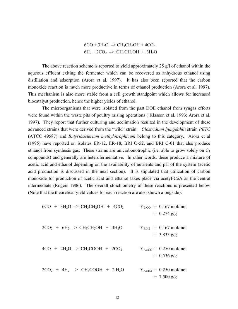
12
6CO + 3H2O –> CH3CH2OH + 4CO2 6H2 + 2CO2 –> CH3CH2OH + 3H2O The above reaction scheme is reported to yield approximately 25 g/l of ethanol within the aqueous effluent exiting the fermenter which can be recovered as anhydrous ethanol using distillation and adsorption (Arora et al. 1997). It has also been reported that the carbon monoxide reaction is much more productive in terms of ethanol production (Arora et al. 1997). This mechanism is also more stable from a cell growth standpoint which allows for increased biocatalyst production, hence the higher yields of ethanol. The microorganisms that were isolated from the past DOE ethanol from syngas efforts were found within the waste pits of poultry raising operations ( Klasson et al. 1993; Arora et al. 1997). They report that further culturing and acclimation resulted in the development of these advanced strains that were derived from the “wild” strain. Clostridium ljungdahlii strain PETC (ATCC 49587) and Butyribacterium methylotrophicum belong to this category. Arora et al (1995) have reported on isolates ER-12, ER-18, BRI O-52, and BRI C-01 that also produce ethanol from synthesis gas. These strains are unicarbonotrophic (i.e. able to grow solely on C1 compounds) and generally are heterofermentative. In other words, these produce a mixture of acetic acid and ethanol depending on the availability of nutrients and pH of the system (acetic acid production is discussed in the next section). It is stipulated that utilization of carbon monoxide for production of acetic acid and ethanol takes place via acetyl-CoA as the central intermediate (Rogers 1986). The overall stoichiometry of these reactions is presented below (Note that the theoretical yield values for each reaction are also shown alongside): 6CO + 3H2O –> CH3CH2OH + 4CO2 YE/CO = 0.167 mol/mol = 0.274 g/g 2CO2 + 6H2 –> CH3CH2OH + 3H2O YE/H2 = 0.167 mol/mol = 3.833 g/g 4CO + 2H2O –> CH3COOH + 2CO2 YAc/CO = 0.250 mol/mol = 0.536 g/g 2CO2 + 4H2 –> CH3COOH + 2 H2O YAc/H2 = 0.250 mol/mol = 7.500 g/g
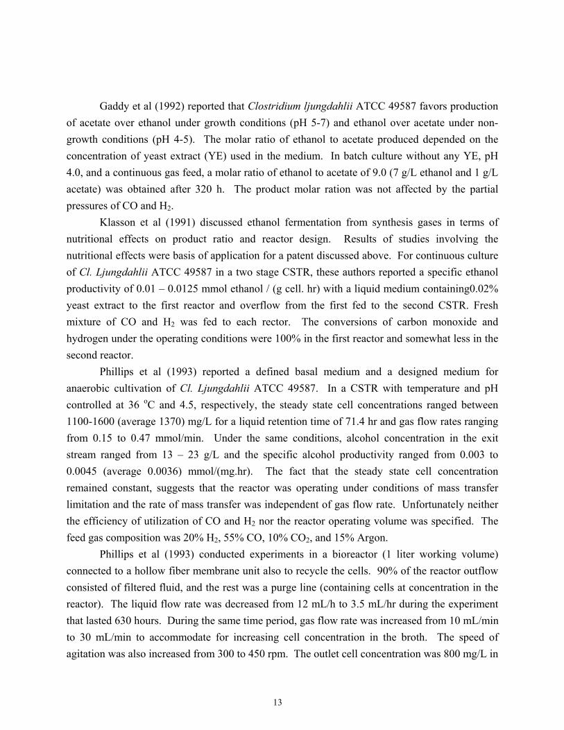
13
Gaddy et al (1992) reported that Clostridium ljungdahlii ATCC 49587 favors production of acetate over ethanol under growth conditions (pH 5-7) and ethanol over acetate under non-growth conditions (pH 4-5). The molar ratio of ethanol to acetate produced depended on the concentration of yeast extract (YE) used in the medium. In batch culture without any YE, pH 4.0, and a continuous gas feed, a molar ratio of ethanol to acetate of 9.0 (7 g/L ethanol and 1 g/L acetate) was obtained after 320 h. The product molar ration was not affected by the partial pressures of CO and H2. Klasson et al (1991) discussed ethanol fermentation from synthesis gases in terms of nutritional effects on product ratio and reactor design. Results of studies involving the nutritional effects were basis of application for a patent discussed above. For continuous culture of Cl. Ljungdahlii ATCC 49587 in a two stage CSTR, these authors reported a specific ethanol productivity of 0.01 – 0.0125 mmol ethanol / (g cell. hr) with a liquid medium containing0.02% yeast extract to the first reactor and overflow from the first fed to the second CSTR. Fresh mixture of CO and H2 was fed to each rector. The conversions of carbon monoxide and hydrogen under the operating conditions were 100% in the first reactor and somewhat less in the second reactor. Phillips et al (1993) reported a defined basal medium and a designed medium for anaerobic cultivation of Cl. Ljungdahlii ATCC 49587. In a CSTR with temperature and pH controlled at 36 oC and 4.5, respectively, the steady state cell concentrations ranged between 1100-1600 (average 1370) mg/L for a liquid retention time of 71.4 hr and gas flow rates ranging from 0.15 to 0.47 mmol/min. Under the same conditions, alcohol concentration in the exit stream ranged from 13 – 23 g/L and the specific alcohol productivity ranged from 0.003 to 0.0045 (average 0.0036) mmol/(mg.hr). The fact that the steady state cell concentration remained constant, suggests that the reactor was operating under conditions of mass transfer limitation and the rate of mass transfer was independent of gas flow rate. Unfortunately neither the efficiency of utilization of CO and H2 nor the reactor operating volume was specified. The feed gas composition was 20% H2, 55% CO, 10% CO2, and 15% Argon. Phillips et al (1993) conducted experiments in a bioreactor (1 liter working volume) connected to a hollow fiber membrane unit also to recycle the cells. 90% of the reactor outflow consisted of filtered fluid, and the rest was a purge line (containing cells at concentration in the reactor). The liquid flow rate was decreased from 12 mL/h to 3.5 mL/hr during the experiment that lasted 630 hours. During the same time period, gas flow rate was increased from 10 mL/min to 30 mL/min to accommodate for increasing cell concentration in the broth. The speed of agitation was also increased from 300 to 450 rpm. The outlet cell concentration was 800 mg/L in

14
the beginning and it increased linearly after 150 hours of operation to 3500 mg/L at 600 hours. Between 150 – 500 hours, the conversions of CO and H2 were constant at 90% and 70%, respectively. Over the same time frame, the concentration of ethanol in the exit stream increased from 6 g/L to 48 g/L; the concentration of acetic acid were between 5 g/L to 3 g/L. No data were provided concerning the time course of the operating conditions. However, assuming that the cell recycle was initiated at 150 hr and the gas and liquid flow rates were 10 mL/min and 12 mL/hr at 150 hr and 30 mL/min and 3.5 mL/hr at 530 hr, some of the relevant system parameters can be estimated as shown in Table 1. Arora et al (1995) have presented results of ethanol fermentation from refinery waste gases. The composition of feed gas was CO 65%, H2 20%, CO2 11%, 4% CH4. The continuous cultures were conducted at 38.8 oC and 550 rpm utilizing a basal salt medium with vitamin supplement. For gas retention time of 14 min and liquid dilution rate of 0.04 hr-1, Cl. Ljungdahlii cultivation resulted in an average CO conversion of 70% and H2 conversion of 30%. The system output showed cyclic behavior and the maximum ethanol concentration obtained was 12 g/L. The maximum acetic acid concentration was 16 g/L. When experiments were conducted with variable gas flow rate to keep the CO conversion constant at 80% at a liquid dilution rate of 0.071 hr-1, ethanol concentration in the exit was 9 g/L with the gas residence time between 10-35 min, but the concentration of acetate varied between 9-22 g/L. With a different isolate of Cl. Ljungdahlii (BRI O-52), CSTR operation with liquid retention time of 24 hr and gas retention time of 26 min, resulted in a maximum ethanol concentration of 20 g/L in the broth. The stable ethanol, acetate, and cell concentrations in the exit stream were 10.5-11 g/L, 2-3 g/L, and 1.5-2.0 g/L, respectively. CO conversions ranged from 85-90 % and H2 conversions from 20-30%. CSTR experiments (Arora et al. 1995) conducted with another isolate (BRI C-01) resulted in ethanol concentrations between 20-24 g/L, acetic acid concentration of 3-4 g/L, 85% CO conversion, and 50% H2 conversion using a liquid retention time of 32 hr and gas retention time of 14.2 min. The composition of feed gas was 34% CO, 32% H2, 5% CH4, and 29% CO2. In CSTR experiments with cell recycle [Arora et al 1996], the extent of cell purging (no cell purging means complete cell recycle) influenced the ethanol concentration and productivity. In a one-stage CSTR with strain BRI O-52, the following data were reported by Arora et al. (1996):
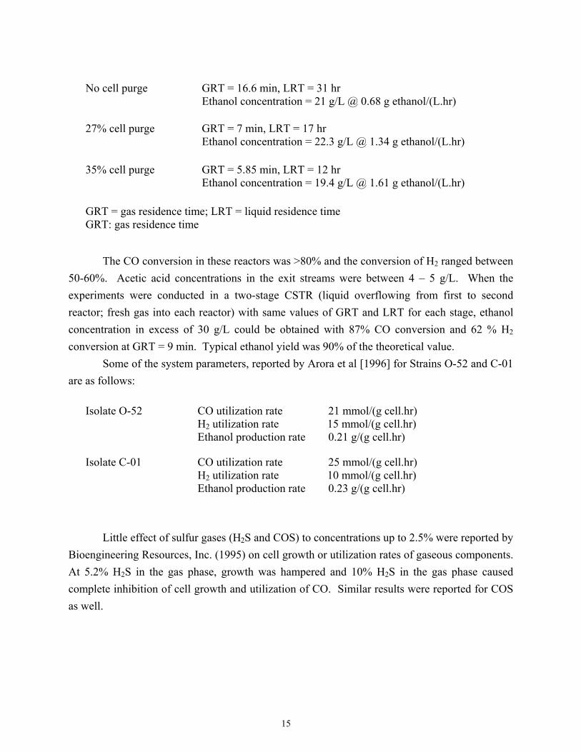
15
No cell purge GRT = 16.6 min, LRT = 31 hr Ethanol concentration = 21 g/L @ 0.68 g ethanol/(L.hr)
27% cell purge GRT = 7 min, LRT = 17 hr Ethanol concentration = 22.3 g/L @ 1.34 g ethanol/(L.hr)
35% cell purge GRT = 5.85 min, LRT = 12 hr Ethanol concentration = 19.4 g/L @ 1.61 g ethanol/(L.hr)
GRT = gas residence time; LRT = liquid residence time GRT: gas residence time
The CO conversion in these reactors was >80% and the conversion of H2 ranged between 50-60%. Acetic acid concentrations in the exit streams were between 4 – 5 g/L. When the experiments were conducted in a two-stage CSTR (liquid overflowing from first to second reactor; fresh gas into each reactor) with same values of GRT and LRT for each stage, ethanol concentration in excess of 30 g/L could be obtained with 87% CO conversion and 62 % H2 conversion at GRT = 9 min. Typical ethanol yield was 90% of the theoretical value. Some of the system parameters, reported by Arora et al [1996] for Strains O-52 and C-01 are as follows:
Isolate O-52 CO utilization rate 21 mmol/(g cell.hr) H2 utilization rate 15 mmol/(g cell.hr) Ethanol production rate 0.21 g/(g cell.hr)
Isolate C-01 CO utilization rate 25 mmol/(g cell.hr) H2 utilization rate 10 mmol/(g cell.hr) Ethanol production rate 0.23 g/(g cell.hr)
Little effect of sulfur gases (H2S and COS) to concentrations up to 2.5% were reported by Bioengineering Resources, Inc. (1995) on cell growth or utilization rates of gaseous components. At 5.2% H2S in the gas phase, growth was hampered and 10% H2S in the gas phase caused complete inhibition of cell growth and utilization of CO. Similar results were reported for COS as well.

16
Acetic Acid Production Studies indicate that under fermentation conditions favoring ethanol production, acetic acid is also produced (Klasson et al. 1991). Acetic acid producing, unicarbonoautrophic organisms of note that are stable under the fermentation conditions discussed above include Acetobacterium woodii, Butyribacterium methylotrophicum, Clostridium thermoaceticum, Eubacterium limosum, Peptostreptococcus productus, Rhodopseudomonas gelatinosa, and Rhodospirillum rubrum belong to this category. Worden et al. (1991) reported that the C. thermoaceticum type strain Fontaine grows rapidly on H2/CO2 and can be adapted to grow on CO as an energy source. The P. productus strain U-1 is capable of growth either on CO alone or on H2/CO2 (Lorowitz and Bryant 1984). Acetobacterium woodii can grow on H2/CO2 but can be adapted to grow on CO alone (Kerby et al. 1983). P. productus grows with a doubling time of around 2 hours and can tolerate as much as 90% CO in the gas phase (Klasson et al. 1991). The toxicity depends on the concentration of dissolved CO in liquid phase and can be avoided as long as gas-liquid mass transfer of CO limits cell growth. Dissolved CO tensions greater than 60-80 kPa inhibit cell growth. Butyribacterium methylotrophicum can also grow on H2/CO2 as well as on CO after adaptation (Worden et al. 1991). This strain produces acetic acid, butyric acid, ethanol, and butyric acid, whole relative proportions depend on pH of broth. On 100% CO, decreasing pH resulted in production of more reduced products (butyric acid, alcohols). Arora et al. (1997) report that approximately 5 g/l of acetic acid is formed following the mechanism detailed below, under conditions producing approximately 25 g/l of ethanol within the same fermenter (5:1 product yield): 4CO + 2H2O –> CH3COOH + 2CO2 2H2 + 4CO2 –> CH3COOH + 2H2O Currently, the acetic acid formed within the fermentation step ends up as the major component of the aqueous stream produced from the ethanol separation step (as a distillation bottoms). This stream is often considered a wastewater to be treated within a treatment plant prior to discharge. Alternative uses of the acetate within the fermentation process, such as recirculation, was evaluated with little potential noted because of alcohol production inhibition within the fermenter (Arora et al. 1997). It is interesting to point out that slight modification of the fermentation process does result in a much higher yield of acetic acid with little ethanol being formed (this mechanism is of likely interest to federal agencies other than DOE, such as USDA).

17
Technical Challenges Facing ME Concept A key issue that will challenge the stability of the fermenter is the maintenance of isolate purity within industrial-scale fermenters. From a microbiological standpoint, the ecosystem provided by fermenters used for producing ethanol from syngas may be conducive to the establishment of microbial contaminants (i.e. organisms that establish themselves within the fermenter that compete for nutrients and eventually inhibit or completely disrupt ethanol production). The methanogenic bacteria (Methanobacterium formicicum, Methanobrevibacter smithii, Methanosarcina barkeri, Methanospirillum hungate) form methane from hydrogen and carbon dioxide. For example, given the presence of sufficient nutrients under the REDOX conditions used within syngas fermenters there is a good potential for the establishment of these methanogenic organisms which produce methane using the scheme below: CO2 + 4H2 –> CH4 + 2H2O The establishment of methanogens is problematic because they convert the gas constituents that would have produced ethanol into a product of limited value compared to ethanol and acetic acid. Additionally, these organisms compete for nutrients which are intentionally maintained at near stressed levels (results in higher ethanol yields); thereby, scavenging the limited nutrients present, possibly, to the extent of adversely affecting ethanol production. The currently subscribed technique for preventing establishment of methanogens is the presence of the carbon monoxide within the syngas feed, which is toxic to methanogens (Arora et al. 1997); however, as discussed above, it is hoped that increased utilization of carbon monoxide can be obtained for maximizing ethanol production, thus increasing the potential for methanogen establishment. Some bacteria (Methanosarcina barkeri, Methanothrix soehngenii) form methane from acetate. CH3COOH –> CH4 + CO2 Methanothrix soehngenii does not utilize CO2 and H2. On the other hand, Methanosarcina barkeri utilizes acetate only when CO2 and H2 are absent from the system. Outside of evaluating the growth potential of methanogens, a screening of other potential biological contaminants needs to be initiated in order to determine what other bacterial contaminants may be problematic during full-scale application (under less than ideal sterility conditions). This effort should provide insight into potential preventive protocols that may have to be initiated to preserve isolate integrity.
18
Another issue that addresses a very practical problem facing potential commercial development is the management of the acetic acid formed as a secondary fermentation by-product (see above discussions). The management of acetic acid was evaluated in the past DOE funded effort. Recirculation of the distillation bottoms to the head of the plant was studied with little or no success noted. Currently, most facilities under consideration are planning to treat the distillation bottoms as a process wastewater. It is believed that treating an acetic acid laden wastewater (estimated by Arora et al. [1997] to be approximately 5,000 mg/l) containing this high BOD is an expensive option. Aerobic biotreatment is the most popular waste treatment technique for industrial wastewaters. However, unpublished studies at MSU indicates a high BOD mass conversion rate from sodium acetate which represents a relatively high organic loading that will make aerobic biotreatment costly for the management of the wastewaters produced by the current designs for ethanol-from-syngas facilities. Therefore, it likely some form of anaerobic treatment should be implemented as a pretreatment step prior to aerobic biotreatment as a final polishing step. This biotreatment configuration is common for treating high strength wastes such as poultry processing wastewaters and slaughter house wastewaters. Evaluation of the Production of Ethanol from ME Syngas (Modeling Effort) An evaluation of the potential for producing ethanol from the ME syngas was performed using a spreadsheet model that incorporated reaction constants reported in other studies. This effort was initiated to assess the net yield of ethanol for a given syngas composition that may be delivered by the ME gasifier. Design composition The composition of the syngas used in this evaluation (on a dry weight basis) was based on Mississippi Ethanol pilot plant results and will herein be considered the “Base Condition” in the analysis of ethanol production from varying syngas compositions. These Base Conditions are listed below: H2 46.6 % CO 28.0 % CO2 15.0 % CH4 7.0 % C2H4 2.0 %

19
C6H14 0.7 % C6H6 0.7 % Gas flow rate (dry) : 460 moles/hr Gas flow rate (wet) : 530 moles/hr Reactor type: The selected reactor configuration for this analysis will be a One Stage CSTR (continuous stirred tank reactor) assumed to be operating at steady state (SS) conditions under the operating conditions (rpm and type of mass transfer unit) listed below: CO transfer rate = 40 mmols/(L.hr) H2 transfer rate = 11 mmols/(L.hr) These numbers may change if the mole fraction of CO and H2 in the inlet change, but this change will not be considered. Additional key parameters are: Yield of cells on CO = YX/CO = 0.0308 g/mol Yield of ethanol on CO = YE/CO = 0.072 mol/mol Yield of ethanol on H2 = YE/H2 = 0.072 mol/mol Yield of acetic acid on CO = Yac/CO = 0.0034 mol/mol Yield of acetic acid on H2 = Yac/H2 = 0.0034 mol/mol Gas residence time : 16 minutes Liquid residence time : 100 hours Purge stream : 5%; Filtered stream : 95% The CO and hydrogen transfer rates were estimated from the data reported by Klasson et al. (1993) under conditions of cell recycle at 530 hours of operation. The yield data were also those estimated from the data of Klasson et al. (1993). The purge stream was set so that the cell concentration in the broth would be around 2-6 g/L. The gas and liquid residence times were modified from Klasson’s data in the light of a different gas composition in the present case. Material balance calculations were conducted around a CSTR with cell recycle. The results are presented in the next section. These include, working volume of reactor (VL, Liters), liquid
20
through put through the reactor (F, L/hr), cell concentration in the reactor (CX, g/L), concentrations of ethanol and acetic acid in reactor effluent (CE and CAc, g/L), ethanol production rate (EPR, gal/day), and percent conversion efficiencies of CO and H2. The following variations from the base case were also calculated to evaluate potential changes in system operation or improvements in fermenter performance:
a) Change in gas transfer rates: These can be introduced by changing the speed of agitation in the CSTR or by modifying the gas-liquid exchange conditions. b) Changes in the ethanol and acetate yield coefficients. These reflect improvements in the composition of media due to optimization studies. It should be noted that the yield values used in the base case are approximately 50% of the theoretically estimated values reported in this text earlier. Literature reports suggest that it is possible to achieve as high as 90% of the theoretical yields. c) Changes in gas composition due to improvements in the technology for production of synthesis gas. The gas composition from the pilot plant operated by Mississippi Ethanol were apparently targeted to achieve a 2:1 molar ratio of hydrogen and carbon monoxide needed for catalytic conversions. For biological conversions, it will be desirable to achieve as high a concentration of carbon monoxide and literature reports suggest that CO fractions as high as 65% can be achieved.
Results The results of calculations have been presented in Table 2. For a given gas flow rate, the volume of reactor and liquid flow rate are specified by the gas and liquid residence times (GRT and LRT). For the specified conditions (gas flow rate of 460 lb-mol./hr; gas residence time 16 minutes and liquid residence time 100 hr), the operating capacity of the reactors was estimated to be 330,000 gallons and the net liquid through put rate 55 gallons/min (79,200 gallons per day). The simulations here have been considered only for the case of mass transfer limitation of utilization of carbon monoxide and hydrogen by the cells. Under these conditions, the amounts of CO and hydrogen utilized were functions only of their mass transfer rates. As a result, the production of ethanol was influenced only by the mass transfer rates and the conversion efficiencies of CO and H2. The four variables investigated in these simulations were the syngas composition, the yields of ethanol and acetic acid on syngas components, the mass transfer rates, and the liquid residence time. While the effects are somewhat obvious, it is imperative to pay attention to where the improvements would be most effective. For the specified gas composition in the first base case (46.6% Hydrogen and 28% CO), the conversion efficiency of CO is already very high (85.3%). Hence, attempts to improve the mass transfer rates are not as effective as the improvements in

21
medium composition so that a better product yield can be obtained. Improvements in mass transfer rates would cause a maximum of 15% increase in ethanol production while media optimization to increase ethanol yield on CO and hydrogen from 0.072 mol/mol (43% of theoretical) to 0.144 mol /mol (86% of theoretical) would increase ethanol production rate 100% (from 1,671 gallons per day to 3,342 gallons per day). However, if the gas composition is changed from (46.6% H2 and 28% CO) to (35% H2 and 45% CO), the gas utilization efficiency under the state mass transfer rates (40 mmol CO/L.h and 11 mmol H2/L.h) decreases to 53% for CO and 18.8 % for hydrogen. In such a case, improvements in mass transfer rates to 72 mmol CO/L.h and 19.8 mmol H2/L.h (80% increase) would cause ethanol production to increase from 1,671 gallons/day to 3,008 gallons per day. When coupled with improved medium (100% increase in ethanol yield), the net ethanol production rate would rise to 6,015 gallons per day. Since literature suggests that synthesis gas can be produced with CO fraction as high as 65%, simulations were also conducted with a syngas mixture containing 60% CO and 20% H2. With this gas composition, the base case resulted in 39.8% CO utilization and 32.6% utilization of hydrogen. Due to mass transfer limitation (40 mmol CO/L.h and 11 mmol H2/L.h), the ethanol production from 460 lb mol dry gas per h was still only 1671 gallon anhydrous ethanol per day. However, increase in mass transfer rates by 150% would increase CO utilization (still under conditions of mass transfer limitation for reactor operation, rather than microbial reaction control) to 99.6% and that of hydrogen to 82%. Hence, the ethanol production would rise to 4,177 gallons per day (due to increased efficiency of utilization of CO and hydrogen). When this mass transfer enhancement is coupled with use of improved media, the daily ethanol production from 460 lb mol dry syngas (60% CO and 20% hydrogen) would increase to 8854 gallons per day. Liquid residence time in the reactors influences the concentration of ethanol and acetate in the exit liquid stream. For a liquid residence time (LRT) of 100 hours, the net liquid through put rate is projected to be 55 gallons/min and the concentration of ethanol ranges from 16.8 g/L to 84.5 g/L depending on the composition of syngas, the medium composition, and the reactor mass transfer capacity. When the liquid residence time is decreased to 20 h, the ethanol concentration would drop by a factor of five (3.4 g/L to 16.9 g/L). This may have serious implication on the subsequent costs during ethanol recovery operations. Since, the reactor capacity is determined by the gas residence time (due to gas-liquid mass transfer controlled regime), LRT does not influence the reactor size. Hence, it is not advisable to reduce the reactor LRT. Instead, emphasis should be on reducing the gas residence time while maintaining the high mass transfer rates discussed above. This would require finding reactors with higher gas hold up capacity for the same gas flow rates. It would point to use of recirculating bubble column bioreactors. Such reactors are commonly available and employed, but were not considered here because their impact on the ethanol production cannot be estimated a-

22
priori. The mass transfer rates used in the calculations were estimated from the work of Klasson et al (1993). Summary and Key Concerns The simulations presented here are based on parameters estimated from a continuous culture with cell recycle reported by Klasson et al. (1993). The publication did not provide all the necessary information to calculate the parameters precisely and assumptions were necessary in order to get the estimates. The fact that a single experiment and several assumptions were used for estimation of parameters makes the base parameter values suspect. All that can be specified at this stage is that these parameter values are conservative and within the theoretical bounds suggested in literature. Given this fact, it would still not be possible to account for the effect of partial cell purging on the system performance, as observed by Arora et al. (1996). The effect of reactor operation on quality of cells produced (their specific growth rate, specific productivity, etc.) must be quantified. What is possible, and was not done at this stage, is to estimate the mass transfer coefficients on the basis of established correlations in Chemical Engineering literature and then link these in a mass transfer with simultaneous microbial uptake of dissolved CO and H2 to establish a pseudo-steady state dissolved concentration of the syngas components. These pseudo-steady state concentrations can then be linked to cell activity with respect to growth rate and product formation capability of microorganisms to arrive at a more realistic picture of the multiphase system. Some aspects of this information, such as the effect of dissolved CO tension on uptake rate of CO, are available from published literature. Others must yet be established by experiments. What this analysis suggests clearly is where the resources need to be committed in order to commercialize the current technology from its present status in as short a time as possible.
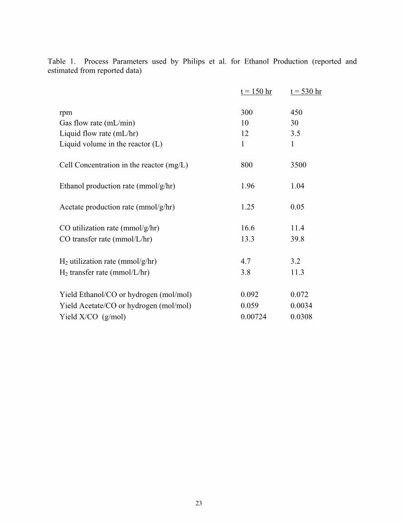
23
Table 1. Process Parameters used by Philips et al. for Ethanol Production (reported and estimated from reported data)
t = 150 hr t = 530 hr rpm 300 450 Gas flow rate (mL/min) 10 30 Liquid flow rate (mL/hr) 12 3.5 Liquid volume in the reactor (L) 1 1 Cell Concentration in the reactor (mg/L) 800 3500 Ethanol production rate (mmol/g/hr) 1.96 1.04 Acetate production rate (mmol/g/hr) 1.25 0.05 CO utilization rate (mmol/g/hr) 16.6 11.4 CO transfer rate (mmol/L/hr) 13.3 39.8 H2 utilization rate (mmol/g/hr) 4.7 3.2 H2 transfer rate (mmol/L/hr) 3.8 11.3 Yield Ethanol/CO or hydrogen (mol/mol) 0.092 0.072 Yield Acetate/CO or hydrogen (mol/mol) 0.059 0.0034 Yield X/CO (g/mol) 0.00724 0.0308
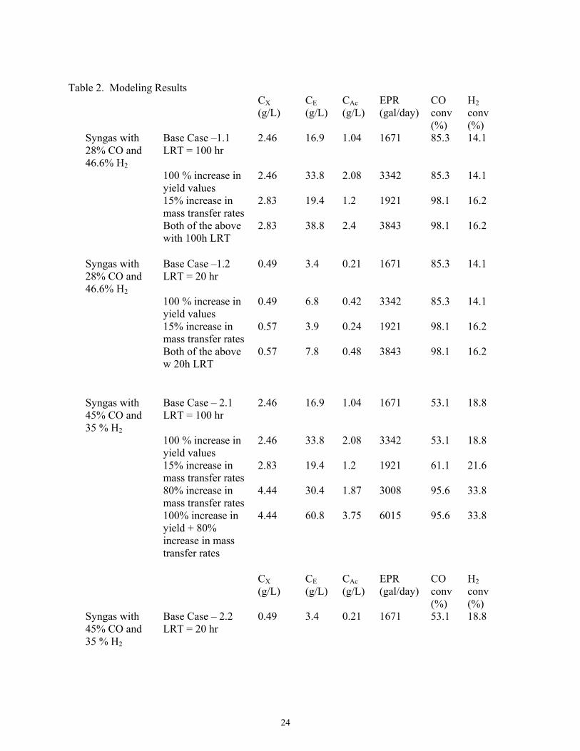
24
Table 2. Modeling Results CX
(g/L) CE (g/L)
CAc (g/L)
EPR (gal/day)
CO conv (%)
H2 conv (%)
Syngas with 28% CO and 46.6% H2
Base Case –1.1 LRT = 100 hr
2.46 16.9 1.04 1671 85.3 14.1
100 % increase in yield values
2.46 33.8 2.08 3342 85.3 14.1
15% increase in mass transfer rates
2.83 19.4 1.2 1921 98.1 16.2
Both of the above with 100h LRT
2.83 38.8 2.4 3843 98.1 16.2
Syngas with 28% CO and 46.6% H2
Base Case –1.2 LRT = 20 hr
0.49 3.4 0.21 1671 85.3 14.1
100 % increase in yield values
0.49 6.8 0.42 3342 85.3 14.1
15% increase in mass transfer rates
0.57 3.9 0.24 1921 98.1 16.2
Both of the above w 20h LRT
0.57 7.8 0.48 3843 98.1 16.2
Syngas with 45% CO and 35 % H2
Base Case – 2.1 LRT = 100 hr
2.46 16.9 1.04 1671 53.1 18.8
100 % increase in yield values
2.46 33.8 2.08 3342 53.1 18.8
15% increase in mass transfer rates
2.83 19.4 1.2 1921 61.1 21.6
80% increase in mass transfer rates
4.44 30.4 1.87 3008 95.6 33.8
100% increase in yield + 80% increase in mass transfer rates
4.44 60.8 3.75 6015 95.6 33.8
CX
(g/L) CE (g/L)
CAc (g/L)
EPR (gal/day)
CO conv (%)
H2 conv (%)
Syngas with 45% CO and 35 % H2
Base Case – 2.2 LRT = 20 hr
0.49 3.4 0.21 1671 53.1 18.8

25
100 % increase
0.49 6.8 0.42 3342 53.1 18.8
15% increase in mass transfer rates
0.57 3.9 0.24 1921 61.6 21.6
80% increase in mass transfer rates
0.89 6.1 0.37 3008 95.6 33.8
100% increase in yield + 80% increase in mass transfer rates
0.89 12.2 0.75 6015 95.6 33.8
Syngas with 60% CO and 20% H2
Base case – 3.1 LRT = 100 h
2.46 16.9 1.04 1671 39.8 32.9
100% increase in yield values
2.46 33.8 2.08 3342 39.8 32.9
80% increase in mass transfer rates
4.44 30.4 1.87 3008 71.7 59.1
150% increase in mass transfer rates
6.16 42.2 2.6 4177 99.6 82.1
100% increase in yield + 150% increase in mass transfer rates
6.16 84.5 5.2 8354 99.6 82.1
Syngas with 60% CO and 20% H2
Base case – 3.2 LRT = 20 h
0.49 3.4 0.21 1671 39.8 32.6
100% increase in yield values
0.49 6.8 0.42 3342 39.8 32.6
80% increase in mass transfer rates
0.89 6.1 0.37 3008 71.7 59.1
150% increase in mass transfer rates
1.23 8.4 0.52 4177 99.6 82.1
CX
(g/L) CE (g/L)
CAc (g/L)
EPR (gal/day)
CO conv (%)
H2 conv (%)
Syngas with 60% CO and 20% H2
100% increase in yield + 150% increase in mass transfer rates
1.23 16.9 1.04 8854 99.6 82.1
26
Chapter IV. Update on On-going Laboratory Activities with Bacterial Isolates (Ethanol Producers)
The MSU Microbiology Laboratory under the leadership of Dr. Lewis Brown has received and been experimenting with two isolates that were obtained from the American Type Culture Collection (ATCC) archives (Rockville, MD). Experimentation has focused on both culturing of the organisms and assessing their relative ethanol production capabilities. Additional efforts underway include evaluation of other potential bacterial sources for hopeful discovery of better functioning organisms and optimization of fermentation broth composition with hopes to reduce the cost of this important process input stream. Cultures Pure Cultures of Clostridium ljungdahlii (#55383) and Clostridium acetobutylicum (#824) were obtained from the ATCC. Culturing of these isolates was initiated with the results of these efforts summarized in the subsequent paragraphs of this chapter. Media {tc "Media " \l 2} The dehydrated cultures obtained from ATCC were activated by inoculation into growth medium (Table I). After sufficient growth was observed, transfers into ethanol medium (Table II) were performed. Oxoid Reinforced Clostridial Medium was used as the growth medium for C. acetobutylicum. The C. acetobutylicum was also subsequently transferred to the ethanol medium. All cultures were incubated in an incubators maintained at 37�C. The synthetic Syngas was purchased from and mixed by NexAir Inc. and was composed of 15% CO2, 15% CH4, 30% CO, and 40% H2. Culture Vessels Vacutainer tubes with approximately 10ml volume were used for growth of the cultures on growth medium and initially used for growth on ethanol medium. Because the Vacutainer tubes did not supply an adequate amount of head-space above the medium, 70ml vials equipped with Mininert valves were substituted. {tc " Vacutainer tubes with approximately 10ml volume were used for growth of the cultures on growth medium and initially used for growth on ethanol medium. Because the Vacutainer tubes did not supply an adequate amount of head-space above the medium, 70ml vials equipped with Mininert valves were substituted. " \l 2}

27
Ethanol Determination {tc "Ethanol Determination " \l 2} Analysis of the culture medium for ethanol was performed on a Varian CP 3800 gas chromatograph equipped with a Phenomenex ZB-Wax column. This column is specifically designed for the analysis of samples where water is the solvent. The method used for ethanol analysis was 80�C hold for 2min, 25�C per min ramp to 150�C and hold for 5min with 1µl of sample injected on the column. The amount of ethanol present in the sample was determined by comparison with a standard curve (Fig. 1). Pure Culture Studies Pure cultures of Clostridium ljungdahlii and Clostridium acetobutylicum were transferred anaerobically under nitrogen from sealed ATCC vials to growth medium. Medium components were first prepared, mixed, and the pH adjusted to 4.5. The medium was then placed into the anaerobic chamber and nitrogen gas bubbled through the medium for about 1 hour. In order to obtain sterile medium, Vacutainer tubes were used to pull 5ml of medium through a 0.22µm MCE membrane filter attached to the end of a 60ml syringe. The Vacutainer tubes were then opened under nitrogen and the dehydrated cultures subsequently added. First attempts to activate the cultures failed. This was probably due to the presence of trace amounts of oxygen in the anaerobic chamber. However, the procedure was repeated and the second attempt to grow the cultures was successful. Use of sterile Vacutainer tubes was abandoned due to the lack of sufficient head-space (~5ml) above the medium for adequate amounts of carbon monoxide. When vials equipped with Mininert valves containing 9ml media, 1ml inoculum, and 60ml of Syn-Gas were employed, much greater yields of ethanol were achieved. In Pursuit of a Better Medium Due to the large number of components in both the growth medium and the ethanol medium, several experiments are being conducted to find a less complex, and therefore less expensive, medium. Preliminary results show that substitution of Pacific Ocean sea water for the trace element solution yield similar amounts of ethanol produced.

28
Table I. Clostridium ljungdahlii growth medium. {tc "
{tc " " \l 2}

29
Table I. Clostridium ljungdahlii growth medium. " \l 2}

30
Table II. C. ljungdahlii and C. acetobutylicum medium for producing ethanol {tc "

31
Table II. C. ljungdahlii and C. acetobutylicum medium for producing ethanol " \l 2}

32
{tc "

33
"} " \l 2
0
20000
40000
60000
80000
100000
120000
0 0.0001 0.0002 0.0003 0.0004 0.0005 0.0006 0.0007 0.0008 0.0009
Ethanol (g/ml)
Are
a C
ount
Figure 1. Ethanol standard curve.

34
Chapter V. Separations Considerations Two separation steps are required within the fermenter system. The first involves the separation of bacterial cells from the fermenter effluent for recycle back into the fermenter. A membrane separator system is planned for incorporation into the fermenter facility because of the efficiency of these units and the poor settling characteristics reported for these cells (Arora et al. 1997). A Zenon-type membrane separator has been selected without any additional consideration given to alternative techniques for cell separation because of the extensive work reported by Arora et al. (1997). However, during potential future pilot scale testing, other types of membrane separators may be evaluated for reducing capital costs. The aqueous stream exiting the cell separators are then pumped into a distillation system for ethanol separation and purification. Traditional distillation and purification techniques are proposed. Ethanol separation and purification is the only product recovery proposed because the capture of acetic acid for commercial purposes is not considered economically feasible due to the low concentration gradient (~4 g/l) and low separations character from aqueous media. The focus of the remainder of this chapter will be on the sizing and sourcing of the complete distillation system. This effort was done independent of Arrington Engineering for use by ME as a comparison for evaluation of costing reasonableness of both estimates. Recovery and Dehydration of Ethanol After the ethanol is produced in the reactor, it must then be separated from the reactor effluent and dehydrated. The reactor effluent will contain approximately 25 mg/l or higher alcohol along with a small amount of acetate and possibly some solid fraction. The actual separation will take place in three different processes. The first step should be an initial separation using a multi-effect evaporator system which will yield a concentrated alcohol stream of about 7% and a second bottoms stream containing the bulk of the reactor effluent including the acetate and solid fraction. In the second step, the 7% alcohol stream will be distilled in a conventional distillation column to near azeotrope concentration. The third and final step is the dehydration of the azeotrope. The overall target for energy consumption in the recovery systems is a combined 15,000 BTU/gallon or less. In order to understand the first step, an Energy-Use Simulation Study was performed to determine the energy requirements for employing a multi-effect evaporator system. The parameters that were specified in the study were to keep the overall energy use as low a possible. It was determined that a set of four evaporator effects seemed to yield the best value for ethanol recovery based on the energy expended with a yield of 7% alcohol product.

35
For the second step, the alcohol product stream is fed to a plate-type distillation column where a near-azeotrope mixture of alcohol and water is produced. The alcohol concentration at this point will be near 192 proof. Energy requirements for this step in the process are intense and economic considerations dictate that careful planing be done to integrate distillation heat requirements with the gasification section of the plant. Dehydration of the ethanol to 199+ proof is the third and final processing step. For the current size ethanol facility, dehydration by using molecular sieve packed beds is the most economical alternative. The 192 proof ethanol vapor product leaving the ethanol-water still will be dehydrated while remaining in the vapor phase. Dehydration in this manner will result in an energy savings when compared to liquid phase dehydration. The downside of molecular sieve dehydration is that the molecular sieves must be heated to relatively high temperatures (+450o F) for regeneration which means that expensive energy must be procured. If the energy for dehydration must be purchased from outside vendors in the form or electricity of fuel, then the molecular sieve technique is superior. However, should large quantities of low temperature waste energy be available, in the form of 10 psig steam, then azeotropic distillation with an added solvent would be the preferred method of dehydration. This process is carried out by feeding the near azeotropic mixture of ethanol and water to a set of two distillation columns. A solvent (entrainer) is added and a ternary azeotrope forms. The ternary azeotrope leaves the first column as overhead product with the pure dehydrated ethanol exiting as the bottoms product. The second column is used to recover the solvent as the overhead product with water leaving as the bottoms product. If hexane is used as the entrainer, the columns can be operated at near atmospheric pressure. The current study shows that recovery of the very low concentration acetate fraction (6 to 7 g/l) may not be economically feasible at this time. The technology for accomplishing this separation will depend on a breakthrough in membrane separation techniques or the perfection of a suitable liquid extraction scheme. Membrane technology is still in the development phase and it is expensive while liquid extraction, a mature technology, presents problems with carryover of solvent to the treated stream. Thus, acetate recovery should be excluded as a factor in determining economics at this stage of the project.

36
Equipment Estimates All equipment estimates are budget cost estimates and may be taken as plus/minus 30%. Installed costs are taken as four times the equipment costs unless otherwise noted. Evaporator Section: Evaporator Number 1 Internal Diameter 3 feet Heat Transfer Area 440 square feet Equipment Cost $ 23,806 Evaporator Number 2 Internal Diameter 3.5 feet Heat Transfer Area 1,650 square feet Equipment Cost $33,140 Evaporator Number 3 Internal Diameter 4.0 feet Heat Transfer Area 1,400 square feet Equipment Cost $31,780 Evaporator Number 4 Internal Diameter 5 feet Heat Transfer Area 1,000 square feet Condenser Size 220 square feet Equipment Cost $39,600 Total Cost of Evaporator Section Installed: 4 x ($23,806 + $33,140 +31,780 + 39,600) = $ 513,300 Distillation Tower Section The following provides an estimate for the requirements of the distillation system. Note that the accuracy is plus/minus 30%. Total system flowrate used in this calculation was for a 9,000 gpd.
1. Distillation System - Stream is the fermentation yield (~30 g/l ethanol), post-cell separation @ 150 gpm (~9000 gpd). Number required is one with a 80 inch

37
ID, 14 trays, 95 feet in height, and constructed of 316L stainless steel. Estimated cost of $525,000 for materials and $315,000 for labor. 2. Condenser - Configured to coupled with the distillation tower. One unit is needed that is 13 sf, shell-in-tube with a floating head and 0.75 inch OD removable bundles on a 1 inch triangular pitch that will be constructed of 304 stainless steel tubes. Estimated costs are $5,000 for equipment costs and $1,500 for labor. 3. Heat Exchanger - This unit is to be used for ethanol separation. One unit configured as 70 sf, 8 inch ID shell with twenty-six 16 foot long tubes plumbed as 2 passes with forty-nine, 2 inch baffle spacing. The unit will be a shell in tube configuration with carbon steel composition with a floating head and removable bundles (0.75 inch OD on a 1 inch triangular pitch made of 304 stainless steel tubes). Estimated costs are $7,500 for equipment and $2,500 for labor. 4. Dehydration System - This unit will be used for dewatering of the ethanol azeotrope. A single unit is required that will designed for a 7 gpm flowrate (Delta-T Model TS Dehydration system with molecular sieves). Estimated costs are $185,000 for equipment and $110,000 for labor. 5. Vent Scrubber Tank (effluent holding) - Capacity for holding separated effluent is 33 gallons (2 foot ID with 2 feet in height). The unit should be vertical configured and construction of 316L stainless steel. Estimated costs are $5,500 for equipment and $1,700 for labor. 6. Stillage Collection Tank - The capacity for this tank is 68,000 gallons with a 20 foot ID and 30 feet in height that should be constructed of 316L stainless steel (vertical aligned with a cover). Estimated costs are $114,750 for equipment and $34,500 for labor. 7. Stillage Hold Tank - The capacity for this tank is 8,500 gallons with a 10 foot ID and 15 feet in height that should be constructed of 316L stainless steel (vertical aligned with a cover). Estimated costs are $40,250 for equipment and $12,100 for labor. 8. Ethanol Collection Tank - The capacity for this tank is 3,300 gallons with a 7 foot ID and 11 feet in height that should be constructed of 316L stainless steel (vertical aligned with a cover). Estimated costs are $25,100 for equipment and $7,600 for labor. 9. Scrubber Pump (effluent recirculating/transfer) - Suggested pump is a cast chrome nickel alloy cased centrifugal pump that operates under a10 gpm at a 50 foot head (0.25 hp). Estimated costs are $3,800 for equipment and $1,200 for labor.

38
10. Feed Pump - Suggested pump is a cast chrome nickel alloy cased centrifugal pump that operates under a 131 gpm at a 60 foot head (3 hp). Estimated costs are $4,600 for equipment and $1,800 for labor. 11. Stillage Pump - Suggested pump is a cast chrome nickel alloy cased centrifugal pump that operates under a 129 gpm at a 100 foot head (5 hp). Estimated costs are $5,900 for equipment and $1,800 for labor. 12. Stillage Transfer Pump - Suggested pump is a cast chrome nickel alloy cased centrifugal pump that operates under a 129 gpm at a 50 foot head (3 hp). Estimated costs are $6,200 for equipment and $1,900 for labor. 13. Ethanol Transfer Pump - Suggested pump is a cast chrome nickel alloy cased centrifugal pump that operates under a6 gpm at a 50 foot head (0.25 hp). Estimated costs are $3,800 for equipment and $1,200 for labor. 14. Spent Yeast Transfer Pump - Suggested pump is a cast chrome nickel alloy cased centrifugal pump that operates under a 2 gpm at a 50 foot head (0.25 hp). Estimated costs are $3,800 for equipment and $1,200 for labor. 15. Cooling Tower (Induced draft) - A single tower is required that should be configured as a 165 gpm flow, 63 sf, 9 foot ID, 1 foot tower, 5 foot basin with 7 hp that is to be constructed of 304 stainless steel with a concrete basin (cross flow arrangement). Estimated costs are $82,750 for equipment and $50,000 for labor.
The above listed equipment results in a total cost of approximately $1,600,000 with this number representing a plus/minus 30% range estimate. It should be noted that this estimate is based on base line fermenter effluent quality discussed earlier in this report. Vendor Sources The following section presents a listing of potential sources of key equipment and supporting supplies. Pumps, Valves, and Instrumentation These very common hardware may be purchased separately from various of vendors and therefore a listing will not be provided. Additionally, significant sizing calculations are required to appropriately select vendors. Distillation The distillation system listed and the molecular sieve drying unit is available from:

39
Delta T Corporation 460 McLaws Circle Williamsburg, Virginia 23185 USA tel: 757-220-2955 fax: 757-229-1705 Listed below are other possible sources for distillation towers, evaporator units, tanks, and heat exchangers: Distillation Tower Manufactures: Mason Mfg. 4900 N. Brush College Rd., P.O. Box 3577 Decatur, IL 62524 Phone: 217-875-7708 FAX: 217-875-7709 Website: http://www.masonmfg.com E-mail: [email protected] Boardman, Inc. 1135 S. McKinley Oklahoma City, OK 73108 Phone: 405-634-5434 Toll Free: 800-880-5434 FAX: 405-632-6948 Website: http://www.boardmaninc.com E-mail: [email protected] Imperial Steel Tank Co. 3234 W. 31st St. Chicago, IL 60623-5085 Phone: 773-523-7117 Toll Free: 800-282-1574 FAX: 773-523-9002 Evaporator Components Buffalo Technologies Corp., Buflovak Div. P.O. Box 1041 Buffalo, NY 14240

40
Phone: 716-895-2100 Toll Free: 800-332-2419 FAX: 716-895-8263 E-mail: [email protected] Doyle & Roth Mfg. Co. Inc. 26 Broadway, Suite 911 New York, NY 10004 Phone: 212-269-7840 FAX: 212-248-4780 E-mail: [email protected] Imperial Steel Tank Co. 3234 W. 31st St. Chicago, IL 60623-5085 Phone: 773-523-7117 Toll Free: 800-282-1574 FAX: 773-523-9002

41
Chapter VI. Fermenter Considerations Various types of fermenters can be used to produce ethanol using the type of bacteria proposed for the ME system. Taylor et al. (1997) report that approximately $0.05 per cost of producing one gallon of ethanol are attributed to the capital costs of the fermenters. Most discussions pertaining to the fermenter types used for producing ethanol using this technique have centered on the use of suspended growth fermenters with syngas (quenched to mesophilic temperatures) bubbled into the reactor using spargers. Fermenters of this type are often referred to as bubble column fermenters (Kawagoe et al. 1999). Various configurations can be made with this basic design which may include designs involving sub-stream air lifting compartments and sparging with microbubbles (Bredwell and Worden 1998; Kawagoe et al. 1999). However, research has shown the simplest, bubble column reactor, i.e. in-vessel sparged reactor - has excellent performance over more elaborate designs (Kawagoe et al. 1999). Due to the low solubility of hydrogen, carbon monoxide, and carbon dioxide, fermenter designs used for fermentation of syngas must include mass transfer efficiencies are a key consideration (Klasson et al. 1990). Klasson et al. also report that both suspended growth and attached growth were acceptable configurations for ethanol or methane production from syngas fermentation. Although outside of the scope of this effort, considerations of air treatment exiting the fermenter must be explored. A review of the modeling effort within this report indicates that several options for managing the off-gases are feasible including flaring or possible reuse of a recovered fuel if hydrogen levels allow. Mixing can be provided via mechanical or gas-lifting. Currently, it is assumed that gas-lifting will be sufficient for provided effective mixing due to the poor settling characteristics reported by Arora et al. (1997) which is usually indicative of low SG cells which should be mixed using mixing eddies offered by gas lifting. Alternatively, an attached growth fermenter is feasible as an option to suspended growth fermenters (Kunduru and Pometto 1996; Taylor et al. 1997). Various configurations of the attached growth fermenter are feasible which includes trickle and fully-saturated reactors (Markov et al. 1997). Attached growth fermenters (aka. trickle-bed) have been found during waste treatment to provide a more stable bioreactor than a suspended growth units (Zappi et al. 1993). Albeit not with fermentation of syngas, some research with fermentation-produced ethanol within attached/immobilized growth reactors has yielded very positive results (Shah and Cheryan 1994; Webb et al. 1994). Kesava and Panda (1996) found an attached growth fermenter to produce higher conversions of sugar to ethanol over a suspended growth system. Another benefit to the use of attached growth bioreactors is that cell separation techniques are not required down-stream which eliminates the need for membrane cell separators. The membrane separation step represents
42
approximately 25% of total capital construction costs of plant construction (based on the design evaluation by MSU presented later in this document). Additionally, improved mass transfer of the syngas constituents into the fermentation broth may be realized using a counter-current flow trickle bed fermentation column (Blanch and Clark 1997). These issues may be evaluated during performance the pilot scale study, but for sake of initial costing and generation of a preliminary design, a suspended growth, bubble fermenter will be the configuration of choice at this juncture. Biomass Feedstock Materials In terms of syngas production, there are four primary feed stock sources within reasonable geographic range of Mississippi. These are coal, natural gas, biomass, and regeneration gases from catalytic cracking of crude oil (Arora et al. 1997; Bredwell et al. 1999). Natural gas is a well established technique that is commonly used in industries such as fertilizer manufacturing. In this case, the syngas is generated for the hydrogen (which is reacted with nitrogen to form ammonia) and the carbon species are wasted. Mississippi Chemical Inc., a large fertilizer manufacturer located in Yazoo City, Mississippi, uses natural gas for feed stock and the CO is reformed into CO2 for release (Personal discussion with company officials, December, 2000). Zhang et al. (2000) discuss catalytic production of syngas from methane in which a novel nickel-aluminum catalyst was used. Their work indicated significant improvement in syngas production yield and catalyst stability (which is a big issue with catalytic conversion). The production of coal in United States exceeded 109 tons in 1990 (Lepkowski 1991). It was expected to be twice as much by the year 2000 (Exxon, 2000). United States reserves of coal were estimated at equivalent to 750 billion barrels of crude oil, roughly equal to 300 years’ supply of petroleum at its 1982 consumption rates (Specks and Klussmann 1982). Of this, approximately 60% is sub-bituminous coal with an energy content of 13,000 – 19000 kJ/kg. Gasification of coal (a combination of pyrolysis and combustion) under controlled conditions results into formation of a mixture of carbon monoxide (CO), hydrogen (H2), and carbon dioxide (CO2) (Simbeck et al. 1983). Small quantities of sulfur (H2S, COS), carbon (CH4, C2H6. C6H14), and nitrogen compounds are also produced (Simbeck et al. 1982). The calorific content of the synthesis gas ranges between 6000 – 17,000 kJ/m3 depending on whether air or pure oxygen was used in the gasification process. One of the most intriguing biomass sources is waste products generated from the processing of both cultured and wild biomass (Brooks and Ingram 1995; Arora et al. 1997). Of all the feed stocks mentioned above, ethanol produced from biomass represents an alternative fuel generally considered one of the most promising (Lynd et al. 1991; DOE 1999). This fully renewable resource can be produced from biomass collected from cultivated and/or wild sources, both of which are energetically charged from energy derived from the sun and absorbed carbon

43
dioxide (Bashir and Lee 1994). The total energy potential of the earth’s current annual biomass production is estimated to be 2,740 quads (1 quad = 1016 BTUs), while the current total world energy annual usage is estimated to be only 340 quads, representing an eight-fold higher potential energy source over current needs (DOE 1999). Interestingly enough, Claassen et al. (1999) report that lignocellulosic biomass that is not amenable to most fermentations represents over 50% of the world’s total biomass making aggressive processes, such as syngas fermentation, particularly attractive for using waste biomass. Engler et al. (1975) propose a design for a gasifier that used cattle manure produced at feedlots for generation of syngas. They report a capital cost of $6,500,00 and $3,125,000 total installation costs for a 1,000 ton per day gasifier system (note: these are mid-1970s costs). The wood products industry in Mississippi is the largest manufacturing sector in the state employing over 65,000 employees and has a raw materials stock estimated to be over 3.1 billion dollars (MSU 1996). One in every four jobs in Mississippi is forest product related. These activities include both raw lumber and wood product manufacturing (Mississippi is the second largest furniture producing state). Over 4 million tons of wood product waste annually are not being used for any beneficial product development thus requiring disposal (MSU 1996). According to experiments conducted at the USDA Cotton Ginning Laboratory in Stoneville, MS, an average of 100 pounds of cotton waste is produced for each bale of cotton ginned. About 1,850,000 bales of cotton are ginned in the Delta counties of Mississippi. This ginning produces approximately 92,500 tons of cotton waste. In addition, cotton seed processing wastes (linters) from processing plants in Mississippi are approximately 4,000 tons per year. As an interesting point of note, disposal of these waste products is a major problem for the many small cotton ginning businesses. The composition of synthesis gas depends on gasification conditions and the type and composition of the carbonaceous substance used. Synthesis gas formed from coal gasification and following the quenching and purification steps, contains 40-65% CO, 25-35% H2, 1-20% CO2, 0-7% CH4, and only a very small quantity of other compounds (Coffin, 1984). A typical composition of synthesis gas has been reported by McCullough et al. (1982) as 65% CO, 30% H2, 2% CO2 and the balance of water and sulfur gases. The fluctuation of syngas composition on product manufacture using the catalytic, abiotic process for is well discussed by Erena et al. (1998). Of particular interest to the current venture is the ability of gasifiers to shift the chemical composition of chemicals within the syngas. Based on the modeling efforts, significant increases in CO composition will yield a more cost effective process because of the increase in net ethanol production. Therefore, gasifier efforts at the ME facility should focus on CO composition as a priority.
44
Envisioned Scale-Up of the ME Concept It is envisioned that centralized, small to medium scale ethanol production facilities can be located throughout biomass production areas which will convert the biomass (either cultured or waste) into a utilizable and profitable fuel source. Additionally, since many of these areas are among the poorest regions of the United States, a much needed economic “shot-in-the-arm” may be delivered to these economically impoverished areas with the realization of this vision. One final note with regard to the locality of ME operations is that a significant portion of the industrial base present in Mississippi and Louisiana is heavily oriented toward petroleum refining allowing for easy implementation of ethanol-gasoline blending as policies and incentives change. Some of this vision has already been brought to accomplished within the State of Mississippi in that, to date, two entities within the State of Mississippi have constructed full-scale facilities that convert waste products into synthesis gas (syngas). One, of course, is ME, but the other full scale facility in Mississippi has selected an abiotic catalytic process to produce ethanol (located in Aberdeen, MS). Neither plant is currently producing chemicals on a regular basis, yet both continue to pursue developmental opportunities. Members of the MSU Chemical Engineering Department are currently working with the Aberdeen facility in terms of catalyst selection and optimization. None of the ME Fermentation Development Team are involved in the Aberdeen Plant activities. Cost Breakdown for the ME Fermentation Plant This cost estimate was prepared to provide a first-line estimate of the cost range expected for a fermentation system, if a grass roots construction approach was decided by ME at their Winona Site. The capacity of the total system in terms of ethanol production is expected to be approximately 3,500 gpd. The costs of the various process equipment were rounded values collected from vendor surveys and design experience. The major shortcoming of the estimates listed below is that the process parameters will actually vary quite dramatically based on factors such as syngas composition, gas constituent conversion, chemical yields, GRT, and LRT. Therefore, using process parameters calculated during a first-line assessment using average data from literature (Arara et al. 1997), a LRT of 17 hours, GRT of 10 minutes, liquid flowrate of 10 gpm, and fermenter effluent concentration of 25 g/l was used for the estimate provided below.

45
Major Equipment Purchases Fermenters: 4-25,000 gallon units @$7.00 per gallon (based on two vendor estimates) = $700,000 Note: A 17 hour HRT was used for this calculation 1-2,500 gallon stock fermenter* @$7.00 per gallon = $17,500 * Used for archiving a culture of pure isolates for use when the production
fermenters need reseeding of the isolates due to scheduled or accidental shuts. Office/laboratory/control room: 2,000 sf @ $75/sf = $150,000 Warehouse: 10,000 sf @ $40/sf = $400,000 Membrane Biomass Separators: 4-25 gpm Zenon separators (quoted from Zenon) @ $160,000 each = $640,000 Tankage: 2-30,000 gallon holding tanks from fermenters 1-100,000 gallon ethanol storage tank 1-50,000 gallon wastewater storage tank 1-7,500 nutrient feed tank
Total Tankage - 220,000 gallons @$2/gallon (based on actual prices from a chemical plant that has recently purchased tanks) = $440,000
Waste Stream Treatment: 150,000 gpd wastewater plant @ $2/gallon (from vendor estimate) = $300,000 Air treatment (note sure so guessed this) = $200,000 Pumps: Assuming: 4-fermenter pumps 3-chemical feed pumps

46
2-culture fermenter pumps 2-distillation feed pumps 3-wastewater pumps 2-extra in case I missed something Total pumps needed - 16 @ $3,000 (assumed average) = $48,000 Distillation/Dehydrator: As per Cliff George (MSU-CHE) - $900,000 (rounded figure that does not include supporting equipment costs or labor because this will be included in %-based estimation estimates given below as per Peters and Timmerhause [1991]). TOTAL EQUIPMENT ESTIMATE = $3,795,000 Based on The Plant Design Book by Peters and Timmerhaus (1991), the following estimates are presented based on a rounded equipment cost of $3.7 million: Percentage of Capital Cost Outlay (Grass Roots Plant Construction) Item Suggested % Range Selected % Estimated Cost Running Total Major Equipment 15 - 40 50 $3,700,000 $3,700,000 Install Equipment 6 - 14 10 $740,000 $4,440,000 Instrumentation 2 - 8 7 $518,000 $4,958,000 Piping (installed) 3 - 20 10 $740,000 $5,698,000 Electrical (installed) 2 - 10 9 $666,000 $6,364,000 Yard Improvements 2 - 5 4 $296,000 $6,660,000 Service facilities 8 -20 10 $740,000 $7,400,000 100% Indirect Cost Calculations as Suggested by Peters and Timmerhaus are predicted as follows: Engineering/ Constr. Supervis. 4 -21 15 $1,110,000 $8,510,000 Constr. Expense 4 -16 9 $666,000 $9,176,000 Contract. Fee 2 - 6 3 $222,000 $9,398,000 Continency 5 -15 10 $740,000 $10,138,000

47
Summary Based on recommended percentages and fairly accurate costing of actual equipment the recommended budgeting as per this book is approximately $10,200,000. Now, if the equipment cost rearranged to be a higher percentage by taking in account that estimate sources were likely covering their bases and assuming therefore that their estimates are high, than the projected project costs will decrease as follows:
NOTE: Redoing the calculations assuming a 75% equipment cost results as follows: Percentage of Capital Cost Outlay (Grass Roots Plant Construction) Item Suggested % Range Selected % Estimated Cost Running Total Major Equipment 15 - 40 75 $3,700,000 $3,700,000 Install Equipment 6 - 14 5 $246,667 $3,946,667 Instrumentation 2 - 8 5 $246,667 $4,193,334 Piping (installed) 3 - 20 5 $246,667 $4,440,000 Electrical (installed) 2 - 10 5 $246,667 $4,686,668 Yard Improvements 2 - 5 3 $148,000 $4,834,668 Service facilities 8 -20 2 $98,667 $4,933,335 100% Associated Indirect Costs as Suggested by Peters and Timmerhaus: Engineering/ Constr. Supervis. 4 -21 15 $740,000 $5,673,335 Constr. Expense 4 -16 9 $444,000 $6,117,335 Contract. Fee 2 - 6 3 $148,000 $6,265,335 Contingency 5 -15 10 $493,334 $6,758,669 Therefore, the total cost is much lower at approximately $6,750,000; BUT, this does not follow along with the percentages reported in the book. It is important to remember, that this estimate does represent a +/- 30% estimate. In summary, the proposed fermentation facility at the ME Site can be constructed with the $6,750,000 - $10,200,000 cost range. It is strongly suggested that the higher range is much more realistic. Limitations to the Above Costing Effort The above costing estimates serves as only a first-line cost estimate. It is based on many assumptions of scaling issues and process performance. The modeling effort showed significant improvements in ethanol yield based on longer HRTs than 17 hours. These evaluations are continuing among the project team and the results of additional testing reported in an addendum to this report. It is anticipated that the cost for constructing the fermentation system will increase

48
as much as 150% to 300%, yet with these increases, the net production of ethanol is expected to increase dramatically. A close review of the modeling results should provide further insight and justification of the increase in projected construction cost. These variances in terms of equipment size requirements and respective costs indicate how important defining actual process parameters achievable with the ME syngas and MSU organisms. This indicates the extreme value of the proposed pilot scale study on process design and costing. Costing of a Pilot Scale System It is strongly suggested that a pilot-scale study be performed at the ME Site in which a small-scale fermentation pilot be constructed and operated at the site. The syngas fed into this pilot plant should be the actual syngas generated by the ME gasifier. Provisions will have to be made for managing the excess syngas or plans made for storing large quantities of syngas with the gasifier operated on an occasional basis (if feasible in terms of process stability and operations). The pilot plant should produce at least 0.5 gpd of ethanol. Sizing of the various unit processes should be based on targeted ethanol concentrations exiting the fermenters and associated cost of equipment scaled to meet the targeted ethanol production rate (i.e. >0.5 gpd Eth-OH). Potential process parameters of the pilot plant could be: LRT = 50 hours GRT = 20 minutes (Q will be sized to meet fermenter volume & LRT) Fermenter liquid phase flowrate = 0.43 gph Estimated Equipment Costs Fermenter: Commercially available complete laboratory scale fermenters
generally run approximately $7,000 per gallon of wetted volume. Assuming a reduction in controls needs and scale reductions, a cost of $5,000/gallon of wetted fermenter volume will be used.
Volume = HRT * Q = 50 hours * 0.43 gallons/hour = 22 gallons Cost = $5,000/gallon * 22 gallons = $110,000 Note: A 40% costing factor will be included to allow for reconfiguration
of the fermenter to either suspended or attached growth operation. Additional cost is then estimated to be approximately $44,000.

49
Supporting Tankage: Using a 10 day process flow storage capacity yields
a total tankage volume of 5 gallons; therefore, a total tankage volume requirement of approximately 200 gallons of stainless steel tank using a 40X scaling factor. With a tankage cost of $10/gallon, the total cost for tankage is $2,000. Additional feed tanks and other requirements are likely; therefore, another 200 gallons of polyethylene tankage is required at a cost of $2/gallon yields an additional cost of $400. The final tankage cost for the pilot plant is estimated to be $2,400.
Pumps: The following number of pumps are estimated: Fermenter - 4;
process fluids transfer - 4; general pumps - 2. This yields a total of 10 pumps with an estimated cost of $3,000 each. Total cost is estimated to $30,000.
Membrane Separator Unit: The full scale units cost approximately
$7,000/gpm. Assuming a scaling cost factor of 2.6, the cost for a membrane separator will be approximately $9,100.
Tube Settler: This unit will be used to test the feasibility of using a tube-
type clarifier as an alternative to the membrane settler. Estimated cost is $3,000.
Distillation Costs: Assuming a scaling cost factor of 1.5 from the estimate
provided for the full scale system ($90,000/gpm). Therefore, the cost of the separations component of the pilot plant is $67,500.
Onsite Analytical Support: Suggest a gas chromatography System
($50,000), pH meter ($1,000), colorimeter ($500), Specific Ion Analyzer system ($2,500), and associated wet chemistry supplies ($5,000). Total cost is estimated to be $60,000.
The total equipment cost for the pilot unit using the estimate presented above is $323,000. Therefore, a cost of $517,000 is suggested for the pilot system equipment which

50
includes a 50% scaling factor composed of a 30% error margin for costing the equipment and 30% piping/fitting/electrical/yard prep cost. Note that this estimate does not include labor costs

51
Chapter VII. Potential Chemical Products that May be Produced by the Proposed Plant This chapter will focus on listing of potential chemicals that may be produced from the proposed design with little or no process modification. Each potential product description presented below will include information on production modifications/process configuring and selected characteristics of the chemical. Ethanol Ethanol is considered the primary target in terms of chemicals to be produced by the proposed plant. The primary uses of ethanol is with fuel-blending and chemical production. Over 430 million liters of unblended ethanol is used in Europe during the early 1900's for vehicular fuel until petroleum fuels replaced with fuel (Claassen et al. 1999). Energy concerns have heightened the interest in the use of ethanol as a fuel blend and/or additive. Today, over 10% of vehicular fuels in the United States are sold as “gasohol” (ethanol-gasoline blends) that typically contain 10% ethanol (Taylor et al. 1997). Ethanol has also been touted as an excellent anti-knock blend (Taylor et al. 1997). Therefore, ethanol appears to be a particularly appealing product. The reader is referred to the proceeding chapters concerning production techniques to be incorporated within the plant. Ethanol production techniques were discussed earlier in this report. However, in terms of overall competition the Mississippi Department of Community and Economic Development in a memorandum to ME (MDCED Memo to ME, 2000) indicated that there were over 60 ethanol production facilities operating or under construction within the United States. They further state that over 90% of these plants are in the Midwest of the United States indicating an advantage in terms of geographic locality to refineries and other potential customers within the Southeastern United States. Ethanol (CAS No. 64-17-5 [aka. ethyl alcohol, grain alcohol, or Eth-OH]) is a primary alcohol that is composed of two carbons within a hydrocarbon structure bonded to a hydroxyl alcohol signature. Selected Physical/Chemical characteristics are listed below (Lewis 1997): Molecular Weight: 46 gr-mole Boiling Point: 78.3oC Viscosity (20oC): 0.0141 cP Vapor Pressure (20oC): 42 mm Hg Flash Point: 55oF Specific Gravity: 0.82

52
Solubility: Fully with water and other polar solvents Acetic Acid Acetic acid production has already been discussed within this report; however, emphasis was placed on reduction of acetic acid yield and not on the targeted production of acetic acid. Clearly, no real modification is required for converting the fermenter system from an ethanol production facility to an acetic acid production facility (some optimization may be required for the microorganisms). Glacial acetic acid (pure product that is >99.8% pure) is the 33rd highest produced chemical in the United States based on volumetric production (Lewis 1997). Commercial uses of industrial grade acetic acid (note that food grade acetic acid in a diluted form is used as vinegar) include manufacturing of vinyl acetate esters, cellulose acetate, and acetic anhydride, the production of plastics, dyes, insecticides, photographic chemicals, latex coagulants, oil-well additives, and textile printing (Lewis 1997). In terms of comparative costs acetic acid generally costs approximately twice that of ethanol (ethanol prices range from $1.00 - $1.50/gallon depending on market conditions and government subsidies). Currently acetic acid is produced by either catalytic liquid/vapor oxidation of petroleum gases, oxidation of acetaldehyde, reaction of methanol and carbon monoxide, and the oxidative fermentation of ethanol. Acetic acid is a clear liquid that has a very characteristic odor. When diluted, acetic acid is not toxic. Acetic acid (CAS No. 64-19-7 [aka. ethanoic acid, vinegar acid, and methane-carboxylic acid]) is the simplest of all carboxylic acids that is composed of two carbons within a hydrocarbon structure highlighted by the signature carboxylic functional group (COOH). Selected Physical/Chemical characteristics are listed below (Lewis 1997): Molecular Weight: 64 gr-mole Boiling Point: 118oC Viscosity (20oC): 1.22 cP Flash Point: 110oF Specific Gravity: 1.05 Solubility: Fully with water and other polar solvents Hydrogen Hydrogen (CAS 1333-75-0) is a diatomic gas that is the most common chemical in the universe. Hydrogen was discovered by Cavendish in 1766 and named by Lavoisier in 1783. Hydrogen is highly flammable with a LEL at 4% and HEL at 75%.

53
Hydrogen is a chemical that is a key additive to many industrial processes. Hydrogen is also a gaseous fuel that has not found a significant market because of safety issues associated with storage (hydrogen was the fuel used within the ill-fated German blimp, The Hindenberg). Uses of hydrogen include the production of many chemicals including ammonia, ethanol, and aniline, crude oil hydrocracking, petroleum hydroforming, hydrogenation of vegetable oils, hydrogenolysis of coal, reducing agent for organic synthesis, oxyhydrogen flaming, high purity metals production, atomic-hydrogen welding, rocket/missile fuel, and cryogenic research (Lewis 1997). Recently, research and development oriented toward fuel cells has deeply heightened the interest in hydrogen and its production. Syngas is considered a highly viable option for hydrogen generation. In fact, technology may be possible to separate the hydrogen from the syngas and the carbon compounds (CO and CO2) used for production of ethanol and/or acetic acid. Additionally, reforming of CO2 into CO is also feasible. This is a important issue since the production of ethanol using unicarbonoautotrophs requires little or no gaseous hydrogen for ethanol or acetic production. Streams containing high levels of CO may be used to produce ethanol or acetic acid. However, the upper threshold of toxicity or inhibition for unicarbonautotrophs has not been found in the literature. There are bacteria capable of directly producing hydrogen from CO and water. The purple non-sulfur bacterium, Rhodopseudomonas gelatinosa, grows in dark with CO as carbon and energy source. Rhodospirillum rubrum is a photosynthetic bacterium and is known to produce hydrogen from carbon monoxide and water using the water-gas shift reaction (Klasson et al. 1993): CO + H2O –> CO2 + H2 This mechanism may be useful for facilities interested in only hydrogen production where syngas is the feed stream. This configuration will require hydrogen separation (already in existence) followed by fermentation for CO to hydrogen conversion. Fermentation of sugars and biomass to produce hydrogen is also gaining technical note (Taguchi et al. 1995; Woodward and Orr 1998). More development is needed with this option to become of high economic feasibility. On a commercial scale, hydrogen is generated by several techniques including reaction of steam with natural gas (reforming), partial oxidation of hydrocarbon gases, gasification of coal, dissociation of ammonia, thermal, catalytic conversion of hydrocarbons, catalytic reaction of methanol and steam, and electrolysis (Lewis 1997).
54
Methane Methane (CAS 74-82-8) is a flammable gas that is the major component of natural gas (approximately 85% - 95%). The LEL of methane is 5%. Methane is used for production of hydrogen, syngas, alcohol, and chlorinated solvents. Methane is also used as a fuel. Production techniques currently used include exploration and recovery as a natural resources, anaerobic digestion, and fermentation of hydrogen and carbon dioxide. The primary value consideration of methane within the ME concept would be the conversion of the hydrogen and carbon dioxide within the gas stream exiting the ethanol fermenter into methane as a recovered fuel for use in the plant. As presented earlier in this report the reaction scheme for producing methane from carbon dioxide and hydrogen is:
CO2 + 4H2 –> CH4 + 2H2O Also as mentioned earlier, the organisms that are capable of performing this reaction are well known. The fermenter configuration required for supporting this activity is also similar to the one proposed for producing methane at the ME Site. Butanol Butanol (CAS 71-36-3) is another product that may be produced from the fermentation of syngas (Kim et al. 1984; Meyer et al. 1986; Worden et al. 1990; Bredwell et al. 1999). Worden et al. (1990) discuss mechanisms and bacteria capable of converting syngas into butanol. Fermentation techniques for production of alcohols, such as butanol and ethanol, are very similar to those used for acetic acid. Acids generally favor higher pH conditions (>5), while alcohols are produced at lower pH’s (typically <5). A generalized scheme for the bacterial conversion of CO to butanol is shown below (Worden et al. 1990): 12CO + 5H2O –> CH3(CH2)2CH2OH + 8CO2 Butanol is a colorless liquid with vinous odor (Lewis 1997). It is used in the production of esters and dyes, as a solvent for resins and coatings, plasticizer, hydraulic fluids, detergent formulations, and as a dehydrating agent (azeotrope distillation). Butanol is produced by the hydrogenation of butyraldehyde and the condensation of acetaldehyde to form crotonaldehyde which is then hydrogenated. Key properties of butanol are (Lewis 1997): SG: 0.811 Boiling Point: 117o C

55
Solubility: 7.7 w% in water (20o C) and fully in other alcohols and ethers Note: Flammable and toxic
Butyric Acid Bredwell et al. (1999) also report that butyric acid (CAS 107-92-6) may also be produced from the fermentation of syngas. The biotic reaction within fermenting syngas that produces butyric acid is (Worden et al. 1990): 10CO + 4H2O –> CH3CH2CH2COOH + 6CO2 Uses of butyric acid include synthesis of butyrate ester perfume and flavorings, pharmaceuticals, deliming agents, disinfectants, emulsifying agents, and gasoline additives (Lewis 1997). Butyric acid is also known as n-butyric acid, butanoic acid, ethylacetic acid, and propylformic acid. This liquid is colorless with very strong obnoxious odor. It is produced as a by-product of hydrocarbon synthesis, via the oxidation of butyraldehyde, or fermentation. Key characteristics are: Boiling Point: 163.5o C SG: 0.958 Vapor Pressure: 0.84 mm Hg (20o C) Solubility: Fully miscible Note: Considered flammable Methanol Methanol (67-56-1) is another chemical that may be produced within syngas-fed fermenters (Reimert 1985). It is also known as wood alcohol and methyl alcohol. It is used in the manufacture of formaldehyde, numerous chemical syntheses reactions, as an antifreeze agent, solvent for nitrocellulose, dehydrator for natural gas, feedstock for the production of proteins, and as a source of hydrogen for fuel cells (Lewis 1997). It is produced via high-pressure catalytic synthesis of syngas or the partial oxidation of natural gas hydrocarbons. Methanol is a colorless liquid that is among the 21 most produced chemicals within the United States (Lewis 1997). Key characteristics of methanol include: SG: 0.792

56
Boiling Point: 64.5o C Viscosity: 0.00593 cP (at 20o C) Vapor Pressure: 92 mm Hg (at 20o C) Solubility: Fully miscible in water, alcohols, and ethers

57
Chapter VIII. Environmental Implications of Ethanol Use as an Alternative Fuel Ethanol has low toxicity, is miscible with water, easily biodegraded in the environment, and produces much less air-borne pollutants in internal combustion engines than petroleum fuels (Verschueren 1983; Kito-Borsa et al. 1998). Since biomass is derived from carbon within the biosphere and after combustion is returned to the biosphere, the natural carbon balance is not changed. Wang et al. (1999) show convincing evidence on the pollution prevention characteristics of ethanol-gasoline blends, especially for E85 formulations (85% ethanol/15% gas). Additionally, they state that many car makers are producing more vehicles with tolerances to burn high %E fuels more efficiently. Thus, the risk posed by ethanol to the environment is significantly lower than that of fuels produced from petroleum and the demand for ethanol will increase with time as these automobile improvements take place. Examples of waste biomass sources that may be used as feed stocks include sawdust, wood chips, cotton ginning waste, bagasse, peanut hulls, sewage sludge, and chicken litter. Disposal of these waste biomass products is challenging the industries producing these wastes in terms of locating disposal facilities and cost (ranging from $15 - $75/ton depending on geographic location and landfill demand). The production of ethanol from these “waste” sources allows for the beneficial utilization of these biomass sources as opposed to the wasting of these carbon sources as a disposal problem. Secondary utilization of waste biomass involves using these materials as a secondary resource for fuels production. Secondary utilization eliminates problems with waste disposal, while fully utilizing the energy value of these biomass materials. Conversely, primary utilization is the process of producing fuels from biomass that is cultured with the main intent of producing ethanol. Mississippi is one of the leading states in agricultural and forestry activity (gauged in terms of production volume, percent land utilization, and per capita involvement). Many of these activities produce a vast quantity of biomass that is simply managed as a waste disposal problem and not viewed as an energy resource. Discussions with biomass-based industries indicate that much of the biomass resources within the Southeastern United Stated (and other places) are being landfilled or open-dumped into uncontrolled waste pits and open areas. In essence, industries are wasting valuable fuel feed stocks by paying to dispose of them or contaminating the environment with these high biochemical oxygen demand (BOD) laden wastes. This predicament is not unique to Mississippi or the United States. The wasting of biomass is a world-wide energy loss and environmental disposal problem.
58
Chapter IX. Review of Arrington Engineering Report After reviewing the report prepared by the Arrington Corporation for the Mississippi Ethanol Gasification Facility, the following comments are made by the Fermentation Team:
1. Within the time constraints, the detail of the overall report is good and the capital cost of $11 million appears reasonable. Both are adequate for planning purposes. 2. Replacing the polyester bags in the baghouse with Gore-Tex membrane bags should eliminate the need for a cyclone prior to the baghouse. Resins from the wood should not plug the Teflon membrane. The membrane bags are more expensive, but last longer with a lower pressure drop. The expense of the bags could be offset by the cost and operation of the cyclone. 3. Replacing post reaction vessels with pipe giving similar residence time will increase the pressure drop in the system. This could impact blower size and operating costs. 4. A one-hour capacity for the Reactor Day (Dry?) Tank should be adequate. Increasing the size to 12-24 hours of operation would not allow for major problems. The uniformity of the feed should be the deciding factor. 5. The double-pipe heat exchanger, E-103, will operate at 1600 �F and 10 psig. How quickly the temperature drop s will have the most impact on suitability. A working temperature of 1600 �F may cause distortion of the exchanger. 6. For safety, two persons should be on-site during all operating hours. More personnel will be needed for pilot plant operation. Automated data collection and having maintenance people on-call could reduce or eliminate an increase in operating staff over what has been suggested. 7. Tank losses from ethanol storage should be addressed – conservation vents, carbon bed adsorbers, and/or tank balancing. All process vents should be controlled. One method of control might be to route the vents to a common header, which could go to a flare or the combustion chamber of the boiler. 8. A storage tank should be considered for the syn-gas between the gasification plant and the ethanol plant. This would be especially useful during downtime of the fermenters or reactors. Storage of CO could lead to the formation of nickel carbonyl, Ni(CO)4, which has a PEL of 7 µg/m3 and carcinogenic properties.

59
Chapter X. References - Agricultural Statistics Board, 1992, NASS-USDA, Cotton Ginnings, January Issue. - Alfantanzi, A. M. and Pickles, C. A. 1992., Materials at High Temperature, 10 (1):51-59. - Aranda, P., Chen, Wen-Janq, Martin, C. R., 1995, Memb. Sci., 99, 185-95. - Arora, D. et al., 1997, Production of Ethanol from Refinery Waste Gases, DOE Final Report (DOE-AL-98770-3) - Arora, D., Basu, R., Breshears, F. S., Gaines, L. D., Hays, K. S., Phillips, J. R., Wilkstrom, C. V., Clausen, E. C., and Gaddy, J. L. 1996. “Production of Ethanol from Refinery Waste Gases. Final Report, April 1994 – July 1997”. DOE/AL/98770-3 (DE98003194). - Arora, D., Basu, R., Phillips, J. R., Wilkstrom, C. V., Clausen, E. C., and Gaddy, J. L. 1995. “Production of Ethanol from Refinery Waste Gases. Phase II. Technology Development”. DOE/AL/98770-1 (DE97006845). - Ayea, E., He, D., and Wang, J., 1993, App. Catal. A: General, V104, pp. 77-85. - Bashir, S. and Lee, S., 1994, Fuel Sci. and Tech. Inter., 12, 11/12. - Bauer, M.W., L. E. Driskill, W. Callen, Snead, M.A., E. J. Mathur, and R.M. Kelly, 1999, J. Bacteriol. 181, 284-90. - Bioengineering Resources, Inc. 1995. “Bench-Scale Demonstration of Biological Production of Ethanol from Coal Synthesis Gas. Topical Report 5: Process Analysis”. DOE/PC/92118-T14 (DE96007018). - Blanch, H. and Clark, D., 1997, Biochemical Engineering, Marcel Dekker Inc. - Borja, R., Banks, C., and Sanchez, E., 1996, J. Biotech., 45, 2. - Bredwell, M. and Worden, M., 1998, Biotech. Prog., V14, pp. 31-38. - Bredwell, M., Srivastava, P., and Worden, M., 1999, Biotech. Prog., V15, pp. 834-844. - Broder, J.D., J. W. Barrier, G. E. Farina, and G. Lightsey, 1985 , Acid Hydrolysis Experimental Facility Results with Corn Stover, ASAE Paper No. 85-30083. - Brooks, T. and Ingram, L., 1995, Biotech. Prog. V11, pp. 619-625. - Bryjak, M., Pozniak, G., Trochimczuk, W., 1992, Agnew. Makromol. Chem. 200 , 93-108. - Bryjak, M. Trochimczuk, W., 1992, Agnew. Makromol. Chem. 200, 111-21. - Business Trends, Nov. 1998, 20, 6. - Business Trends, July 1999, 40, 7. - Cabasso, I.; Liu, Z.Z.; Makenzie, T., 1986, J. Membrane Sci., 28, 109. - Carder, J. H., 1986, Anal. Biochem., 153, 75-9. - Choi, H.S. ; Hino, T. ; Shibata, M. ; Negishi, M. ; Ohya, H., 1992, J. Membrane Sci., 72, 259.
60
- Claassen, P, van Lier, J., Lopez, A., van Niel, E., Sijtsma, L., Stams, A., de Vries, S., and Weusthuis, R, 1999, Appl. Microbiol. Biotech., V52, pp. 741-755. - Coffin, J. M. 1984. “Industrial Coal Gasification: Applications and Economy”. Energy Prog., 4:131-137. - Dai, Y-R., D.Reed, J.Millstein, P.Hartzell, D. Grahame, and D. DeMoll, 1988, Arch. Microbiol. 169: 525-529. - Datta, R. and Zeikus, J. G. 1982. Dev. Ind. Microbiol., 23:131-140. - Davidson, B. and Wyman, C., 1994, Sixteenth Symposium on Biotechnology for Fuels and Chemicals, Humana Press - Dobbek, H., L. Gremer, O. Meyer, and R. Huber, 1999, Proc. Natl. Acad. Sci. USA 96: 8884-8889. - DOE, 1999, Website - biofuels.nrel.gov/bioethanol - DOE, 1999, Website - ott.doe.gov/ofd/ethanol - DOE, 1999, Website - nrel.biotech_symposium - DOE, 1999, Website - nrel.gov/research/indutrial_tech/biomass.html - DOE, 1999, Website - rredc.gov/biomass/doe/rbep/wis.ethanol - Dunning, J. W., and Elbert C. Lathrop, 1984, Process for Saccharifying Plant Materials, Pat. No. 2,450,586. - Dunning, J. W., and Elbert C. Lathrop, 1945, The Saccharification of Agricultural Residues, Ind. Eng. Chem., 24-9. - Elmaleh, S. and Abdelmoumni, L., 1998, Water Sci. Tech., 38, 8/9. - Engler, C., Walawender, W., and Fan, L., 1975, Environmental Science and Technology, V9, N13. - Erena, J., Arandes, J., Bilbao, J., Olazar, M., and de Lasa, H., 1998, J. Chem. Tech., V72, pp. 190-196. - Exxon Co., USA. 1979. “Energy Outlook 2000”. Houston, TX, USA. In ‘Bioprocessing of Coal-derived Synthesis Gases by Anaerobic Bacteria’ by A. J. Grethlein and M. K. Jain, TIBTECH, vol 10, p. 418-423, December 1992. - Fraga, M. and Jordao, E., 1998, React. Kinet. Catal. Letters, V64, N2. - Gaddy, et al., “Production of Ethanol from refinery waste gases,” DOE/AL/98770-3 DE 98003/94 Final Report to DOE under cooperative agreement DE-FC 04-94AL98770, August 1997 - Gaddy, J. L. and Clausen, E. C. 1992. “Clostridium ljungdahlii, An Anaerobic Ethanol and Acetate Producing Microorganism”. US Patent # 5,173,429, issued on Dec 22, 1992. - Goodwin, S. and Zeikus, 1987, J. Bacteriol. 169, 2150-7.

61
- Grethlein, A. J. and Jain, M. K. 1992. “Bioprocessing of Coal-Derived Synthesis Gases by Anaerobic Bacteria”, TIBTECH, 10:418-423. - Harris, E., Hajny, G., Hannan, M., and Rogers, S., 1946, Industrial and Engineering Chemistry, V38, N9. - Hirano, A., Ueda, R., Hirayama, S. and Ogushi, Y., 1997, Energy, V22, N2/3. - Hikmet, R. M., Callister, S., Keller, A., 1988, Polymer 29, 1378- 88. - Horikoshi, K and W.D. Grant, 1998, Extremophiles; Microbial Life in Extreme Environments Wiley - Liss, NY ISBN 0-471-02618-2. - Hsu, Y. and Shieh, W., 1993, Biotechnology and Bioengineering, 41, 347-353. - Ingram et al., 1999, J. Biotech., 15, 855-868. - Jiang, M.; Gronowski, A.A.; Yeager, H.L.; Wu, G.; Kim, J.S.; Eisenberg, A, 1994,. Macromolecules, 27, 6541. - Jo, W.H.; Kang, Y.S.; Kim, H.J., 1993, J. Membrane Sci., 85, 81. - Jørgensen, S., C. E. Vorgias and G. Antranikian, 1997, J. Biol. Chem. 272, 16335-42. - Kadam, K. and Newman, M., 1997, Appl. Microbiol. Biotech., 47, 625-629. - Kang, B.S. and Y.M.Kim, 1999, J. Bacteriol. 181: 5581-5590. - Kawabata, N.; Oda, H., 1989, Biotechnol. Bioeng., 34, 1045. - Kawabata, N., 1992, Prog. Polym. Sci., 17, 1. - Kawagoe, M., Kawakami, K., Nakamura, Y., Naoe, K., Miki, K., and Noda, H., 1999, Journal of Bioscience and Bioengineering, V87, N1, pp. 116-118. - Kesava, S. and Panda, T., 1996, J. Industrial Micro., V17, pp. 11-14. - Kesting, R. E., 1971, Synthetic Polymer Membranes, McGraw-Hill Inc. - Kim, J. T., Anderson, J. L., 1989, J. Memb. Sci. 47, 163-82. - Kim, H., Bellows, P., Datta, R., and Zeikus, J., 1984, Applied and Env. Micro., V48, N4. - Kita-Borsa, T., Pacas, D., Selim, S., and Cowley, S., 1998, Ind. Engr. Chem. Res., 37, 3366-3374. - Kitani, O., and Hall, C., 1989, Biomass Handbook, Gordon and Breach Pub. Co., p. 434-51. - Klasson, K., Ackerson, M., Clausen, E., and Gaddy, J., 1991, Fuel, 70, 5. - Klasson, K., Ackerson, M., Clausen, E., and Gaddy, J., 1993, Fuel, 72, 12. - Klasson, K. T., Gupta, A., Clausen, E. C., and Gaddy, J. L. 1993. “Evaluation of Mass-Transfer and Kinetic Parameters for Rhodospirillum rubrum in a Continuous Stirred Tank Reactor”, Appl. Biochem. Biotechnol., 39/40:549-557. - Koch, R., P. Zabowski, A. Spreinat, and G. Antranikian, 1990, FEMS Microbiol. Lett. 71, 21-6.
62
- Koros, W.J.; Fleming, G.K.; Jordon, S.M.; Kim, T.H.; Hoehn, H.H., 1988, Prog. Polym. Sci., 13, 339. - Kunduru, M. and Pometto, A., J. Ind. Micro., V16, pp. 249-256. - Lightsey, G. R., C.E. George and A.G. Wehr, Evaluation of Cotton Seed Processing Wastes as Feedstocks for the TVA Concentrated Acid Hydrolysis Process, 1991, Final Report to Ms. Dept.of Economic and Comm. Dev. - Lepkowski, W. 1991. Chem. Eng. News.,V69:20-31. - Lewis, R., 1997, Hawley’s Condensed Chemical Dictionary, Van Nostrand Reinhold Pub. - Lin, C. and Chang, R., 1999, J. Chem. Tech. Biotech., V74, pp. 948-500. - Linden, J. C. 1988. In ‘Handbook on Anaerobic Fermentations’, L. E. Erickson and Y.-C. D. Fung (Eds.), pp. 59-80, Marcel Dekker. - Lorowitz, W. H. and Bryant, M. P. 1984. Appl. Environ. Microbiol., 47:961. - Lundberg, R. D., Phillips, R. R., 1982, J. Polym. Sci, Polym. Phys. Ed., 20, 1143-54. - Lynd, L., Cushman, J., Nichols, R., and Wyman, C., 1991, Science, 251, 4999 1318. - Machio, G., Koufopanos, C., and Lucchesi, A. 1992., Bioresources Technol., 42:219-231. - Madhukar, G. R., Elmore, B. B., and Huckabay, H. K. 1996. “Microbial Conversion of Synthesis Gas Components to Useful Fuels and Chemicals”, Appl. Biochem. Biotechnol., 57/58:243-251. - Markov, S., Weaver, P., and Seibert, M., 1997, Applied Biochemistry and Biotechnology, V63 - 65. - Marlatt, J. and Datta, R., 1986, Biotech. Progress, 2, 1. - Matsudaira, P.T, ed., 1988, A Practical Guide to Protein and Peptide Purification for Microsequencing, Academic Press NY. ISBN 0-12-480280-X. - Maupin-Furlow, J and J. G. Ferry, 1996, J. Bacteriol. 178: 6849-6856. - McCullough, G. R., Roberts, S. C., and van der Burgt, M. J. 1982. Energy Progr., 2:69-72. In ‘Bioprocessing of Coal-derived Synthesis Gases by Anaerobic Bacteria’ by A. J. Grethlein and M. K. Jain, TIBTECH, vol 10, p. 418-423, December 1992. - Meyer, C., Ross, J., and Papoutsaki, E., 1986, App. Micro. Biotech., 24, 159-167. - Mississippi State University, 1996, Production and Utilization of Industrial Wood and Bark Residues in Mississippi, MDEQ and MSU Extension Service. - Nishio, N., Solveria, R., Hamato, K., and Nagai, S., 1993, J. Fermentation and Bioengineering, 75, 4. - Ono, H., Fujiwara, K., Sugiyama, E., and Yoshida, K., 1990, Inter. Chem. Engr., 30, 3. - Pasternak, M.; Dorawala, T.G., 1991, J. Polym. Sci., Part A, 29, 915. - Pereira, E. and Martin, G., 1993, App. Catal. A.: General, V108, pp. 291-309. - Phillipidis, G., Smith, K., and Wyman, C., 1993, Biotech. And Bioengr., V41, pp. 846-853.

63
- Phillips, J. R., Klasson, K. T., Clausen, E. C>, and Gaddy, J. L. 1993. “Biological Production of Ethanol from Coal Synthesis Gas – Medium Development Studies”, Appl. Biochem. Biotechnol., 39/40:559-571. - Redkar, S., Kuberkar, V., Davis, R., 1996, J. Membrane Sci., 121, 229-42. - Reinmert, R., 1985, Synthetic Fuels, pp. 135-163. - Rogers, P. 1986. “Genetics and Biochemistry of Clostridium Relevant to Development of Fermentation Processes”, Adv. Appl. Microbiol., 31:1-60. - Rondleman, C. and Hohman, N., 1993, Agribusiness, 9, 3. - Salin, M.L. and N.J. Brown-Peterson, 1995, The Archaea: A Laboratory Manual, (F.T. Robb, A.R. Place, K.R. Sowers, H.J. Schreier, S. DasSarma and E.M. Fleischmann eds.), Cold Spring Harbor Press, NY. ISBN 0-87969-397-5. - Sata, T., 1991, J. Appl. Electrochem, 21, 283. - Simbeck, D. R., Dickenson, R. L., and Moll, A. J. 1982. “Coal Gasification, An Overview”. Energy Prog., 2:42-46. - Simbeck, D. R., Dickerson, R. L., and Oliver, E. D. 1983. “Coal Gasification Systems: A Guide to Status, Applications, and Economics”. Mountain View, CA. - Specks, R. and Klussmann, A. 1982., Energy Progr., 2:60. In ‘Bioreactor Design for Synthesis Gas Fermentaions’ by K. T. Klasson, M. D. Ackerson, E. C. Clausen, and J. L. Gaddy, FUEL, vol 70, p. 605-614, May 1991. - Song, S. W., Torkelson, J. M, 1995, Journal of Membrane Science 98, 209-22. - Speece, R., 1996, Anaerobic Biotechnology, Achae Press Inc.
64
- Strathmann, H.,1983, “Synthetic Membranes and Their Preparation,” Proceedings of the NATO Advanced Study Institute on Synthetic Membranes: Science, Engineering and Applications, Alcabideche, Portugal. - Swain, R.L. Bibb, “Ethanol Dehydration Technology: State of the Art,” Presented at the National Alcohol Fuels 1988 Meeting and Exhibition, Washington, DC, 1988. - Taylor, F., Kurantz, M., Goldberg, N., and Craig, J., 1997, Appl. Microbio. Biotech., V48, pp. 311-316. - Tolan, J. and Finn, R., 1987, App. and Env, Micro., V53, N9. - Turner, S. R., Weiss, R. A., Lundberg, R. D., 1985, J. Polym. Sci. Polym. Chem. Ed., 23. - Verschueren, K., 1983, Handbook of Environmental Data on Organic Chemicals, Van Nostrand-Reinhold Pub. - Wang, Y., Gabbard, H., and Pai P., 1991, Journal of Env. Engr., 117, 4. - Wang, M., Saricks, C., and Santini, D., 1999, J. Air and Waste Man. Assoc., Oct., 17- 25. - Wankat, Phillip C., “Equilibrium Staged Separations,” Prentice Hall, Englewood Cliffs, N.J., (1988) - Warden, R., Grethlein, A., Jain, M., and Datta, R., 1991, Fuel, 70, May - Weiss, R. A., Turner, S. R., Lundberg, R. D., 1985, J. Polym. Sci. Polym. Chem. Ed., 23. - Wood, H.G., 1991, FASEB J. 156-163. - Wood, B., Aldrich, H., and Ingram, L., 1997, Biotech. Prog., V13, pp. 232-237. - Wood, B. and Ingram, L., 1992, App. and Env. Micro., V58, N7. - Woodward, J. and Orr, M., 1998, Biotechnology Prog., V14, pp. 897-902. - Worden, R. M., Grethlein, A. J., Jain, M. K., and Datta, R. 1991. “Production of Butanol and Ethanol from Synthesis Gas via Fermentation”, FUEL, 70:615-619. - Worthington Enzyme Manual, Worthington Biochemical Corp. Lakewood, NJ. - Wu, L.G.; Zhu, C.L.; Liu, M., 1994, J. Membrane Sci., 90, 199. - Wu, Y.F. ; Huang, R.Y.M., 1988, J. Appl. Polym. Sci., 36, 1121. - Yerkes, D., Boonyakitsombut, S., and Speece, R., 1997, Water Sci. Tech., 36, 6/7. - Zeikus, J. G. 1983. In ‘Organic Chemicals from Biomass’, D. L. Wise, Ed., pp. 359-383, Benzamin Cummings. - Zhang, Y., Chu, W., Cao, W., Luo, C., Wen, X., and Zhou, K., 2000, Plasma Chemistry and Plasma Processing, V20, N1.

REPORT DOCUMENTATION PAGE
Form Approved OMB NO. 0704-0188
Public reporting burden for this collection of information is estimated to average 1 hour per response, including the time for reviewing instructions, searching existing data sources, gathering and maintaining the data needed, and completing and reviewing the collection of information. Send comments regarding this burden estimate or any other aspect of this collection of information, including suggestions for reducing this burden, to Washington Headquarters Services, Directorate for Information Operations and Reports, 1215 Jefferson Davis Highway, Suite 1204, Arlington, VA 22202-4302, and to the Office of Management and Budget, Paperwork Reduction Project (0704-0188), Washington, DC 20503. 1. AGENCY USE ONLY (Leave blank)
2. REPORT DATE
March 2002
3. REPORT TYPE AND DATES COVERED
Subcontract Report
4. TITLE AND SUBTITLE Final Report from Mississippi Ethanol LLC to the National Renewable Energy Laboratory
6. AUTHOR(S) Mississippi Ethanol LLC
5. FUNDING NUMBERS
7. PERFORMING ORGANIZATION NAME(S) AND ADDRESS(ES)
Mississippi Ethanol, Winona Mississippi
8. PERFORMING ORGANIZATION
REPORT NUMBER
9. SPONSORING/MONITORING AGENCY NAME(S) AND ADDRESS(ES)
National Renewable Energy Laboratory 1617 Cole Blvd. Golden, CO 80401-3393
10. SPONSORING/MONITORING
AGENCY REPORT NUMBER NREL/ST-510-31720
11. SUPPLEMENTARY NOTES
NREL Technical Monitor: Rafael Nieves 12a. DISTRIBUTION/AVAILABILITY STATEMENT
National Technical Information Service U.S. Department of Commerce 5285 Port Royal Road
Springfield, VA 22161
12b. DISTRIBUTION CODE
13. ABSTRACT (Maximum 200 words) The Department of Energy contracted with Mississippi Ethanol LLC to carry out economic and engineering analyses of a process to convert waste cellulosic materials to commercial grade ethanol. This subcontract report defines the process, estimates costs, and evaluates Mississippi Ethanol’s potential for success.
15. NUMBER OF PAGES
14. SUBJECT TERMS ethanol; gasification; fermentation; Mississippi Ethanol; waste; cellulosic material
16. PRICE CODE
17. SECURITY CLASSIFICATION
OF REPORT Unclassified
18. SECURITY CLASSIFICATION
OF THIS PAGE Unclassified
19. SECURITY CLASSIFICATION
OF ABSTRACT Unclassified
20. LIMITATION OF ABSTRACT
UL
NSN 7540-01-280-5500 Standard Form 298 (Rev. 2-89) Prescribed by ANSI Std. Z39-18 298-102