final assig
TRANSCRIPT
AISSMS COLLEGE OF ENGINEERING
TITLE: SECURING CLOUD USING GRAPHICAL PASSWORD AUTHENTICATION
BY
NILESH A. CHANGUNE EXAM NO.B80214213
GANESH T. SHINDE EXAM NO.B80214263
SAGAR B. CHAUGULE EXAM NO.B80214215
SANDEEP V. HELKAR EXAM NO.B80214257
DEPARTMENT OF COMPUTER ENGINEERING
PROJECT GUIDE: PROJECT COORDINATOR:
PROF. R. T. NEMADE PROF. S. S. SHAIKH

ASSIGNMENT NO. 1
DECISION PROBLEM:
Any problem having the answer either zero or one is called a decision problem. Our
system determines whether, for a given input, the action is performed or not. Thus, our system
represents a decision problem. It is known that only a decision problem is NP-complete.
Also since overall complexity of our system is in polynomial time, linear time and it is
deterministic. Hence our system is in NP-Complete.
MATHEMATICAL MODEL:
SYSTEM= {Q,∑,δ,q0,F}
Where SYSTEM=Securing Cloud Using Graphical Password Au.
Q= States of the system.
∑= Finite state of symbols (alphabets)
δ= Transition function
q0= Initial state
F= Final state

Q= {q0,q1, q2, q3,q4,q5,q6,q8,q9,q10,q11,q12,q13}
Where
q0 = Initial State
In this state if user enter the username.if username is invalid then it go q0.if username valid
Then it acess q1.
q1= graphical password application phase In this state user have 3 option signup, signin,
forgot_password.
q2=signin
q3= select same sequence of image
q4= verify database
q5= access the application in cloud stored
q6=logout.
q7= signup new user.
q8= select sequences of user
q9= select sound signature.
q10=save to database.
q11= for forgot password
q12= play sound signature
q13= enter sequence of image
Initial = In this state the user id and password are loaded in cloud database.
∑= {1, 0}
1=State on left side gives correct input and transit to next state.
0=State on right side gives wrong input and transit to next side.
δ = Transition Function
δ:Q *∑=Q
δ:Q*∑=Q

Set Theory:
Let s (be a main set of) ≡ {SDB, LDB, C, A, S, MR, AO}
where,
SDB is the copy of the server database. This database is responsible for storing user information related to cloud interactions. (Elaborate..)
LDB is a set of local database that a user owns. It consists of data tables having data items related to the products and their sales transactions. (Elaborate..)
C is a set of all clients using the server database and mining services from the server. And (c1, c2,c3, ............cn) Є C. (elaborate..)
A is a set of algorithms applied on the input data to get mining results. (Elaborate..)
S is the server component of the system. The server is responsible for registering, authenticating and providing associations to the end user. (Elaborate..)
MR is a set of mining rules that are applied on the input dataset provided by the client from his LDB. And (mr1, mr2,mr3, ............mrn) Є MR (elaborate..)
AO is a set of associations that are extracted from the input and a form the output of the system. (Elaborate..)
Functionalities:
SDB' = RegisterUser(uid, password, fullname, address, country, contact, email);
password = SHA1(input_password);
U = AuthenticateUser(uid, password, SDB');
LDB1 = ManageProducts(pid, product name, cost);
LDB2 = ManageBilling(transactions, items);
LDB = LDB1 + LDB2
ED(Encoded data) = EncodeTransactions(LDB2, EncodingAlgorithm(EA));
UPLOAD(ED);
AO = Apply Mining(ED);
Results = Decode(Download(AO));

NP-COMPLEE PROBLEM:
In mathematical logic, satisfiablity and validity are elementary concepts of semantics. A formula is satisfiable if it is possible to find an interpretation (model) that makes the formula true. A formula is valid if all interpretations make the formula true. The opposites of these concepts are unsatisfiability and invalidity, that is, a formula is unsatisfiable if none of the interpretations make the formula true, and invalid if some such interpretation makes the formula false. These four concepts are related to each other in a manner exactly analogous to Aristotle's square of opposition.
In computer science, the Boolean Satisfiability Problem (sometimes called Propositional Satisfiability Problem and abbreviated as SATISFIABILITY or SAT) is the problem of determining if there exists an interpretation that satisfies a given Boolean formula. In other words, it asks whether the variables of a given Boolean formula can be consistently replaced by the values TRUE or FALSE in such a way that the formula evaluates to TRUE. If this is the case, the formula is called satisfiable. On the other hand, if no such assignment exists, the function expressed by the formula is identically FALSE for all possible variable assignments and the formula is unsatisfiable. For example, the formula "a AND NOT b" is satisfiable because one can find the values a = TRUE and b = FALSE, which make (a AND NOT b) = TRUE. In contrast, "a AND NOT a" is unsatisfiable.
ASSIGNMENT NO.2

PRIMARY MODULES OF SYSTEM:
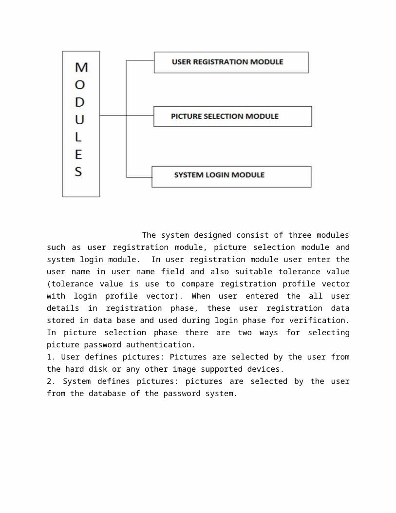
The system designed consist of three modules such as user registration module, picture selection module and system login module. In user registration module user enter the user name in user name field and also suitable tolerance value (tolerance value is use to compare registration profile vector with login profile vector). When user entered the all user details in registration phase, these user registration data stored in data base and used during login phase for verification. In picture selection phase there are two ways for selecting picture password authentication.1. User defines pictures: Pictures are selected by the user from the hard disk or any other image supported devices.2. System defines pictures: pictures are selected by the user from the database of the password system.

In this method when any user try to access the cloud service they will be provided with two option sign in and sign up. At server side calculation in sign up registration is made for user.
Steps of registration:
1) Sign up initiate2) Select password images sequence3) Select manual image 4) Select graphical password for each image5) Calculate hash (digital signature algorithm) for each point using discretized
centralization 6) Accepting string for sound signature7) Register
Steps of sign in
1) Start sign in2) Display image #13) Accept password4) If required generate sound signature5) Calculate hash using digital signature algorithm and discretized centralization6) Authenticate each image7) If invalid signature found show random invalid image for re-verification 8) If re-verification is ok continue accepting graphical password for next image9) If all image authenticate login
In sign in the user have to give username which he or she has given during sign in and select password from given image. validation of user is done then cloud access is given to particular user. They access their account with uploading and downloading facility.

ASSIGNMENT NO. 3
UNIFIED MODELLING LANGUAGE (UML) DIAGRAMS:
Use-Case Diagram:
Use case diagrams are closely connected to scenarios. A scenario is an example of what happens
when someone interacts with the system. In our Project First upon Normal User login & then
authenticated from server side get access to cloud to use his services. If user not legitimate then
he should register first to access cloud services. In registration process user must select graphical
password & sound signature which gives hint in case of user unable to remember the password.
The graphical image password given by user stored in server side database. After completion of
registration process user is authorized to use the available services from cloud. During login
process user must enter the password which is provided by him at the time registration. The
image sequence should be remembered to get access. At that time sound signature gives him hint
to remember the image password. The interaction of user to the cloud with the help of
application which is act as mediator between the client & cloud

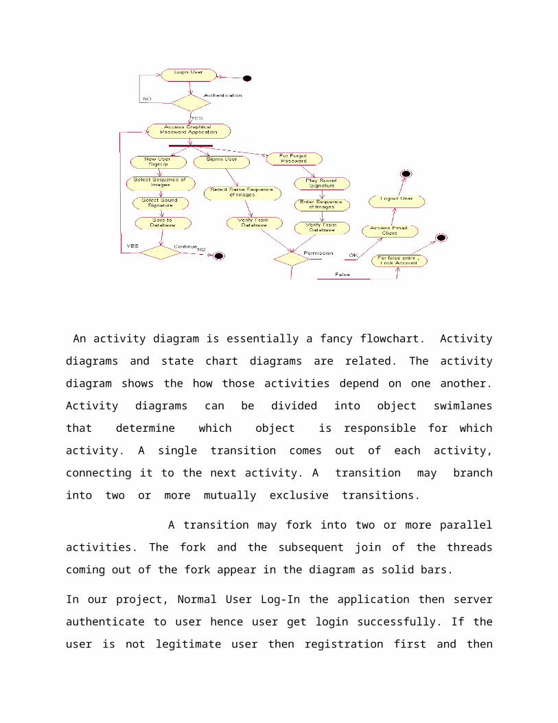
Activity Diagram:
An activity diagram is essentially a fancy flowchart. Activity diagrams and state chart diagrams
are related. The activity diagram shows the how those activities depend on one another. Activity
diagrams can be divided into object swimlanes that determine which object is responsible
for which activity. A single transition comes out of each activity, connecting it to the next
activity. A transition may branch into two or more mutually exclusive transitions.
A transition may fork into two or more parallel activities. The fork and the subsequent
join of the threads coming out of the fork appear in the diagram as solid bars.
In our project, Normal User Log-In the application then server authenticate to user hence user get
login successfully. If the user is not legitimate user then registration first and then login. During
registration user must select sequence of images and sound signature for hint. After registration
complete user must login with desired password. If login successful then user get access of cloud
if unsuccessful must get image sequence from sound signature hint.

Class Diagram:
A Class diagram gives an overview of a system by showing its classes and the
relationships among them. Class diagrams are static. In Class Diagram contain class name,
attribute, and operation.
In Our Project, In class Diagram there are main six classes.
1) User
2) Application
3) Signup
4) SignIn
5) Database
6) Forgot password
In User class, contain attributes like user_name, User_Id. And in login, signup, select images,
signin, forgot password and logout are the operation.
Second is a Application class, In application class there is Java image I/O, Java 2D API, SAPI,
Process Builder are attributes of Application class. There are some operation in application class
like as sign_up, select_image select_soundsignsture update_database, sign_in, forgot_pass etc.In
signup class images and sound are attribute and select image and sound are the operations. Also
in signln only images is attribute and save and update are operation. And last one is
forgot_password class in which images, sound, SAPI And process builder are attribute and play
sound, sequence of images and verify is the operations.
Collaboration Diagram:
Collaboration diagrams are also interaction diagrams. They convey the same information as
sequence diagrams, but they focus on object roles instead of the times that messages are sent.
Each message in a collaboration diagram has a sequence number.
In our project, Normal User Log-In the application then server authenticate to user hence user get
login successfully. If the user is not legitimate user then registration first and then login. During
registration user must select sequence of images and sound signature for hint. After registration
complete user must login with desired password. If login successful then user get access of cloud
if unsuccessful must get image sequence from sound signature hint.
Sequence Diagram:
A sequence diagram is an interaction diagram that details how operations are carried out what
messages are sent and when Sequence diagrams are organized according to time. The time
progresses as you go down the page. The objects involved in the operation are listed from left to
right according to when they take part in the message sequence.
In this diagram for showing message we use arrow. Dotted line shows the lifeline of objects.
There is activation bar below the objects.

ASSIGNMENT NO. 4
TESTING TECHNOLOGY
System testing is a critical phase implementation. Testing of the system involves
hardware devise and debugging of the computer programs and testing information processing
procedures. Testing can be done with text data, which attempts to stimulate all possible
conditions that may arise during processing. If structured programming Methodologies have
been adopted during coding the testing proceeds from higher level to lower level of program
module until the entire program is tested as unit. The testing methods adopted during the testing
of the system were unit testing and integrated testing.
UNIT TESTING:
Unit testing focuses first on the modules, independently of one another, to locate
errors. This enables the tester to detect errors in coding and logical errors that is contained within
that module alone. Those resulting from the interaction between modules are initially avoided.
INTEGRATION TESTING:
Integration testing is a systematic technique for constructing the program structure
while at the same time to uncover the errors associated with interfacing. The objective is to take
unit-tested module and build a program structure that has been detected by designing. It also tests
to find the discrepancies between the system and its original objectives. Subordinate stubs are
replaced one at time actual module. Tests were conducted at each module was integrated. On
completion of each set another stub was replaced with the real module.
FUNCTIONAL TESTING:
Functional testing is a technique in which all the functionalities of the program are
tested to check whether all the functions that where proposed during the planning phase are full
filled. This is also to check that if all the functions proposed are working properly. This is further
done in two phases:
1. One before the integration to see if all the unit components work properly

2. Second to see if they still work properly after they have been integrated to check if some
functional compatibility issues arise.
PERFORMANCE TESTING:
Expected Result
1. The client should be able to connect to the cloud properly without any problems.
2. The connection establishment between the client and the cloud should take
minimal time.
3. The client should be able receive data from the cloud uninterruptedly.
4. Information provided by the application should be correct and as per the user’s
need.
Observation
1. Connection can be established easily provided that the cloud server is on.
2. The connection with the cloud server takes time as it uses Internet connection.
3. Receiving data from the cloud takes time.
4. Information coming from the database is correct.
LOAD / STRESS TESTING:
Expected Result1. Response time should be unaffected irrespective of the no of users.
2. The introduction of the newer clients should not make the cloud to work hap
hazardously.
3. Continuous use of the cloud by different clients should not result into the server
getting slowed down.
4. Response time should not be degraded if there is congestion in network.
Observation The speed of transmission was fine even when the newer clients were getting
added. The response of the server was satisfying even with the introduction of
newer client.