figure 13.1 the up3-bot uses an r/c car battery and r/c servos for drive motors
TRANSCRIPT

Figure 13.1 The UP3-bot uses an R/C car
battery and R/C servos for drive motors.

Figure 13.2 Left: Radio Control Servo Motor and Right: Servo with Case and Gears Removed.

LIBRARY IEEE;
USE IEEE.STD_LOGIC_1164.ALL;
USE IEEE.STD_LOGIC_ARITH.ALL;
USE IEEE.STD_LOGIC_UNSIGNED.ALL;
ENTITY motor_control IS
PORT (clock_1kHz : IN STD_LOGIC;
lmotor_dir, rmotor_dir : IN STD_LOGIC;
lmotor_speed, rmotor_speed : IN STD_LOGIC;
lmotor, rmotor : OUT STD_LOGIC);
END motor_control;
ARCHITECTURE a OF motor_control IS
SIGNAL count_motor: STD_LOGIC_VECTOR( 4 DOWNTO 0 );
BEGIN
PROCESS
BEGIN
-- Count_motor is a 20ms timer
WAIT UNTIL clock_1kHz'EVENT AND clock_1kHz = '1';
IF count_motor /=19 THEN
count_motor <= count_motor + 1;
ELSE
count_motor <= "00000";
END IF;
IF count_motor >= 17 AND count_motor < 18 THEN
-- Don’t generate any pulse for speed = 0
IF lmotor_speed = '0' THEN
lmotor <= '0';
ELSE
lmotor <= '1';
END IF;
IF rmotor_speed = '0' THEN
rmotor <= '0';
ELSE
rmotor <= '1';
END IF;

-- Generate a 1 or 2ms pulse for each motor-- depending on direction-- reverse directions between the two motors because-- of servo mounting on the UP3-bot base
ELSIF count_motor >=18 AND count_motor <19 THENIF lmotor_speed /= '0' THEN CASE lmotor_dir IS
-- FORWARDWHEN '0' => lmotor <= '1';-- REVERSEWHEN '1' =>
lmotor <= '0';WHEN OTHERS => NULL;END CASE;
ELSElmotor <= '0';
END IF;IF rmotor_speed /= '0' THEN CASE rmotor_dir IS
-- FORWARDWHEN '1' => rmotor <= '1';-- REVERSEWHEN '0' =>
rmotor <= '0';WHEN OTHERS => NULL;END CASE;
ELSErmotor <= '0';
END IF;ELSE
lmotor <= '0';rmotor <= '0';
END IF;END PROCESS;
END a;

Figure 13.3 – Three LEDs and phototransistors are mounted on bottom of the Line Tracker board.
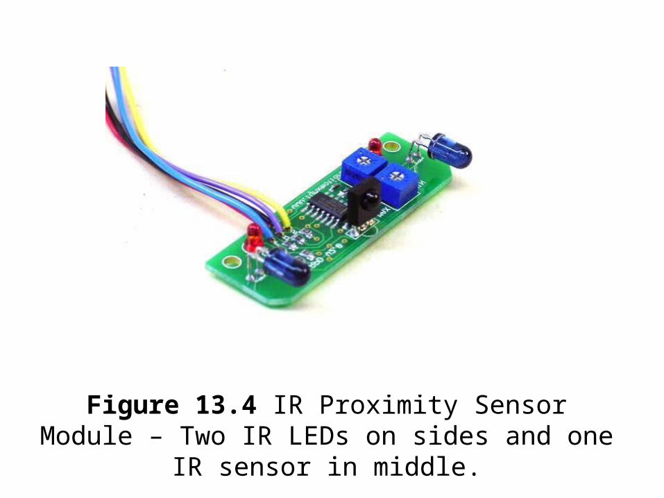
Figure 13.4 IR Proximity Sensor Module – Two IR LEDs on sides and one IR sensor in middle.

Figure 13.5 Proximity detector active sensor area.
Left IR* LED Sensor Right IR LED *Infrared is not visible to the naked eye.
No Return Left LED Area Both LEDs Right LED Area No Return

Figure 13.6 Circuit layout of one LED and the receiver module on the infrared detector.
LED Enable.H Signal Detect.L
5v
38 KHz 180 Ohm
1 of 2 IR LEDs
IR Detector

Figure 13.7 Nubotics WW-01 Wheel Watcher Incremental Encoder System.

Figure 13.8 Devantech SRF10 Ultrasonic Range Finder.

Figure 13.9 Sharp IR Ranging Module.

Figure 13.10 Operation of Sharp IR Ranging Module.
Near Object
Far Object
PositionSensitiveIR Detector
IR LED
ScatteredReflection
Lens Lens

Figure 13.10 Dinsmore 1490 Digital
Compass Sensor

Figure 13.11 PNI Electronic Compass
Module.

Figure 13.12 Small sensor board for an aircraft autopilot system. Photograph ©2004 courtesy of Henrik Christophersen , Georgia Institute of Technology Unmanned Aerial Research Facility.

Figure 13.13 Motorola Single Chip GPS module.

Figure 13.14 Devantech TPA81 Eight Pixel
Thermal Array Sensor.
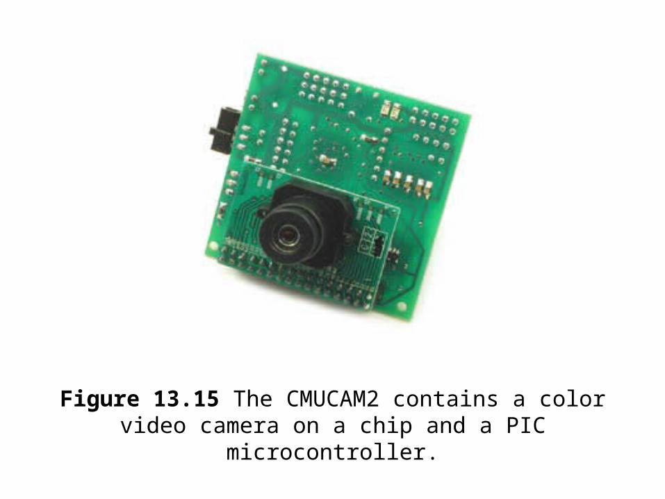
Figure 13.15 The CMUCAM2 contains a color video camera on a chip and a PIC microcontroller.

Figure 13.16 UP3-bot Plexiglas Base with wheel slots and
drill hole locations.
Wheel Slots3/8” by 2 3/4”
Servo CableTwo 3/8”Holes
UP3 Mounting ScrewFour 1/8” Holes
Switch andPower CableTwo 7/32”Holes
3/16” Plexiglass 10.5” Circle
1 3/8”
1 3/8”

Figure 13.17 Bottom view of UP3-bot base showing
battery, servos, wheels, and cabling.

Figure 13.18 Top View of UP3-bot Base with Compass, IR,
and Sonar Sensor Modules.

Figure 13.19 FPGA Controlled Toy R/C Truck with IR
Distance Sensors.

Figure 13.20 Robot Control IP Core with Pulsed Speed &
Steering Control.
FwdRev 1 Bit 0 = Forward/1 = ReverseDirection 3 Bits First bit Left/Right, 2nd and 3rd bit is angle.
0-00 = Left – Straight* 0-01 = Left – Slight Turn 0-10 = Left – Medium Turn
0-11 = Left – Full Turn1-00 = Right – Straight*1-01 = Right – Slight Turn
1-10 = Right – Medium Turn1-11 = Right – Full Turn* Note: 000 and 100 are both Straight
Speed 3 Bits 000 = Stop001 = Slowest Speed: : :111 = Fastest Speed

Figure 13.21 Affect of Duty Cycle on Turning
Angle and Speed.
TurnAngle Speed
Full
1/2
1/3
1/4
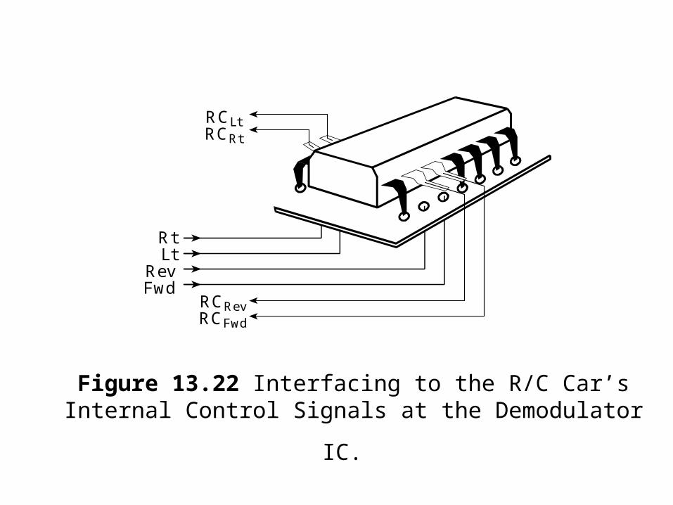
Figure 13.22 Interfacing to the R/C Car’s Internal Control
Signals at the Demodulator IC.
RtLt
RevFwd
RCLtRCRt
RCRevRCFwd

Figure 13.23 Photo Showing Control Modifications to R/C
Car Control Board.

Figure 13.24 Hobbyist R/C model with a CMU camera and R/C PWM servos controlled by an FPGA

Figure 13.25 Lynxmotion Hexpod Walking Robot
Kit with 12 R/C servos.

Figure 13.26 ActiveMedia’s Amigobot robot base controlled
by an FPGA with a Nios Processor