fieldbus system ethercat compatible si unit · 2. installation on equipment in conjunction with...
TRANSCRIPT

No.EX※※-OMO0027-A
PRODUCT NAME
Fieldbus system
EtherCAT compatible SI unit
MODEL / Series/ Product Number
EX600-SEC# EX600-ED#

-1-
No.EX※※-OMO0027-A
Table of Contents
Safety Instructions 2
System Outline 8
Definition and terminology 9
Assembly 10
Mounting and Installation 12
Installation 12
Wiring 14
SI Unit Model Indication and How to Order 15 Summary of Product parts 15
Mounting and Installation 16
Wiring 16
Setting and Adjustment 18
LED Display 21
Specification 23
Specifications 23
Dimensions 24
End plate Model Indication and How to Order 25
Summary of Product parts 25
Mounting and Installation 26
Wiring 26
Specification 27
Specifications 27
Dimensions 27
Maintenance 29
Troubleshooting 30
Parameter Setting 40
Parameter definition and setting 40
Hardware configuration 53
XML file 53
Setting using TwinCAT® System Manager 53
I/O Map 62
Diagnostic 63
Details of diagnostic data 66
Parameter settings using TwinCAT® (SDO communication) 68
Accessories 100
-2-
No.EX※※-OMO0027-A
Safety Instructions These safety instructions are intended to prevent hazardous situations and/or equipment damage. These instructions indicate the level of potential hazard with the labels of "Caution", "Warning" or "Danger". They are all important notes for safety and must be followed in addition to International standards (ISO/IEC) 1) and other safety regulations.
1) ISO 4414: Pneumatic fluid power -- General rules relating to systems ISO 4413: Hydraulic fluid power -- General rules relating to systems IEC 60204-1: Safety of machinery -- Electrical equipment of machines (Part 1: General requirements) ISO 10218-1992: Manipulating industrial robots -Safety. etc.
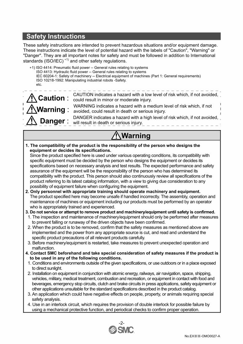
Caution : CAUTION indicates a hazard with a low level of risk which, if not avoided, could result in minor or moderate injury.
Warning : WARNING indicates a hazard with a medium level of risk which, if not avoided, could result in death or serious injury.
Danger : DANGER indicates a hazard with a high level of risk which, if not avoided, will result in death or serious injury.
Warning
1. The compatibility of the product is the responsibility of the person who designs the equipment or decides its specifications. Since the product specified here is used under various operating conditions, its compatibility with specific equipment must be decided by the person who designs the equipment or decides its specifications based on necessary analysis and test results. The expected performance and safety assurance of the equipment will be the responsibility of the person who has determined its compatibility with the product. This person should also continuously review all specifications of the product referring to its latest catalog information, with a view to giving due consideration to any possibility of equipment failure when configuring the equipment.
2. Only personnel with appropriate training should operate machinery and equipment. The product specified here may become unsafe if handled incorrectly. The assembly, operation and maintenance of machines or equipment including our products must be performed by an operator who is appropriately trained and experienced.
3. Do not service or attempt to remove product and machinery/equipment until safety is confirmed. 1. The inspection and maintenance of machinery/equipment should only be performed after measures
to prevent falling or runaway of the driven objects have been confirmed. 2. When the product is to be removed, confirm that the safety measures as mentioned above are
implemented and the power from any appropriate source is cut, and read and understand the specific product precautions of all relevant products carefully.
3. Before machinery/equipment is restarted, take measures to prevent unexpected operation and malfunction.
4. Contact SMC beforehand and take special consideration of safety measures if the product is to be used in any of the following conditions.
1. Conditions and environments outside of the given specifications, or use outdoors or in a place exposed to direct sunlight.
2. Installation on equipment in conjunction with atomic energy, railways, air navigation, space, shipping, vehicles, military, medical treatment, combustion and recreation, or equipment in contact with food and beverages, emergency stop circuits, clutch and brake circuits in press applications, safety equipment or other applications unsuitable for the standard specifications described in the product catalog.
3. An application which could have negative effects on people, property, or animals requiring special safety analysis.
4. Use in an interlock circuit, which requires the provision of double interlock for possible failure by using a mechanical protective function, and periodical checks to confirm proper operation.

-3-
No.EX※※-OMO0027-A
Caution
The product is provided for use in manufacturing industries. The product herein described is basically provided for peaceful use in manufacturing industries. If considering using the product in other industries, consult SMC beforehand and exchange specifications or a contract if necessary. If anything is unclear, contact your nearest sales branch.
Limited warranty and Disclaimer/Compliance Requirements The product used is subject to the following "Limited warranty and Disclaimer" and "Compliance Requirements". Read and accept them before using the product.
Limited warranty and Disclaimer 1. The warranty period of the product is 1 year in service or 1.5 years after the product is delivered,
whichever is first. 2) Also, the product may have specified durability, running distance or replacement parts. Please consult your nearest sales branch.
2. For any failure or damage reported within the warranty period which is clearly our responsibility, a replacement product or necessary parts will be provided. This limited warranty applies only to our product independently, and not to any other damage incurred due to the failure of the product.
3. Prior to using SMC products, please read and understand the warranty terms and disclaimers noted in the specified catalog for the particular products.
2) Vacuum pads are excluded from this 1 year warranty. A vacuum pad is a consumable part, so it is warranted for a year after it is delivered. Also, even within the warranty period, the wear of a product due to the use of the vacuum pad or failure due to the deterioration of rubber material are not covered by the limited warranty.
Compliance Requirements
1. The use of SMC products with production equipment for the manufacture of weapons of mass destruction (WMD) or any other weapon is strictly prohibited.
2. The exports of SMC products or technology from one country to another are governed by the relevant security laws and regulation of the countries involved in the transaction. Prior to the shipment of a SMC product to another country, assure that all local rules governing that export are known and followed.

-4-
No.EX※※-OMO0027-A
Operator This operation manual is intended for those who have knowledge of machinery using pneumatic
equipment, and have sufficient knowledge of assembly, operation and maintenance of such equipment. Only those persons are allowed to perform assembly, operation and maintenance.
Read and understand this operation manual carefully before assembling, operating or providing maintenance to the product.
Precautions
Warning Do not disassemble, modify (including changing the printed circuit board) or repair.
An injury or failure can result.
Do not operate or set with wet hands. This may lead to an electric shock.
Do not operate the product outside of the specifications. Do not use for flammable or harmful fluids. Fire, malfunction, or damage to the product can result. Verify the specifications before use.
Do not operate in an atmosphere containing flammable or explosive gases. Fire or an explosion can result. This product is not designed to be explosion proof.
If using the product in an interlocking circuit: •Provide a double interlocking system, for example a mechanical system. •Check the product regularly for proper operation. Otherwise malfunction can result, causing an accident.
The following instructions must be followed during maintenance: •Turn off the power supply. •Stop the air supply, exhaust the residual pressure and verify that the air is released before performing maintenance.
Otherwise an injury can result.
-5-
No.EX※※-OMO0027-A
Caution When handling, assembling or replacing the units:
•Avoid touching any sharp metal parts of the connectors for connecting units. •When assembling units, take care not to get any fingers caught between units. Injury can result.
•When disassembling units, take care to avoid excessive force. The connection parts of the unit are firmly joined with seals and injury can result.
After maintenance is complete, perform appropriate functional inspections. Stop operation if the equipment does not function properly. Safety cannot be assured in the case of unexpected malfunction.
Provide grounding to assure the safety and noise resistance of the Fieldbus system. Individual grounding should be provided close to the product with a short cable.
NOTE
Follow the instructions given below when designing, selecting and handling the product.
The instructions on design and selection (installation, wiring, environment, adjustment, operation,
maintenance, etc.) described below must also be followed. Product specifications •When conformity to UL is required, the SI unit should be used with a UL1310 Class 2 power supply. •Use the specified voltage. Otherwise failure or malfunction can result.
•The power supply for the unit should be 0 V as the standard for both the power supply for outputs and the power supply for inputs and control.
•Reserve a space for maintenance. Allow sufficient space for maintenance when designing the system.
•Do not remove any nameplates or labels. This can lead to incorrect maintenance, or misreading of the operation manual, which could cause damage or malfunction to the product. It may also result in non-conformity to safety standards.
•Beware of inrush current when the power supply is turned on. Some connected loads can apply an initial charge current which will activate the over current protection function, causing the unit to malfunction.
-6-
No.EX※※-OMO0027-A
Product handling Installation •Do not drop, hit or apply excessive shock to the SI unit. Otherwise damage to the product can result, causing malfunction.
•Tighten to the specified tightening torque. If the tightening torque is exceeded the mounting screws may be broken. IP67 protection cannot be guaranteed if the screws are not tightened to the specified torque.
•If a large manifold valve is mounted, lift the unit so that stress is not applied to the connecting part while transporting. The stress may cause breakage of the connecting part. The unit may become very heavy depending on the combination. Transportation/installation shall be performed by multiple operators.
•Never mount a product in a location that will be used as a foothold. The product may be damaged if excessive force is applied by stepping or climbing onto it.
Wiring •Avoid repeatedly bending or stretching the cables, or placing heavy load on them. Repetitive bending stress or tensile stress can cause breakage of the cable.
•Wire correctly. Incorrect wiring can break the product.
•Do not perform wiring while the power is on. Otherwise damage to the Fieldbus system and/or input or output device can result, causing malfunction.
•Do not route wires and cables together with power or high voltage cables. Otherwise the Fieldbus system and/or input or output device can malfunction due to interference of noise and surge voltage from power and high voltage cables to the signal line. Route the wires (piping) of the Fieldbus system and/or input or output device separately from power or high voltage cables.
•Confirm proper insulation of wiring. Poor insulation (interference from another circuit, poor insulation between terminals, etc.) can lead to excess voltage or current being applied to the product, causing damage.
•Take appropriate measures against noise, such as using a noise filter, when the Fieldbus system is incorporated into equipment. Otherwise noise can cause malfunction.
Environment •Select the proper type of protection according to the environment of operation. IP67 protection is achieved when the following conditions are met.
(1)The units are connected properly with fieldbus cable with M12 connector and power cable with M12 (M8) connector.
(2)Suitable mounting of each unit and manifold valve. (3)Be sure to fit a waterproof cap on any unused connectors.
If using in an environment that is exposed to water splashes, please take measures such as using a cover. Do not use in an environment where moisture or water vapor are present. Otherwise failure and malfunction can result.
•Do not use in a place where the product could be splashed by oil or chemicals. If the product is to be used in an environment containing oils or chemicals such as coolant or cleaning solvent, even for a short time, it may be adversely affected (damage, malfunction etc.).
•Do not use the product in an environment where corrosive gases or fluids could be splashed. Otherwise damage to the product and malfunction can result.
•Do not use in an area where surges are generated. If there is equipment generating large surge near the unit (magnetic type lifter, high frequency inductive furnace, welding machine, motor, etc.), this can cause deterioration of the internal circuitry element of the unit or result in damage. Take measures against the surge sources, and prevent the lines from coming into close contact.

-7-
No.EX※※-OMO0027-A
•When a surge-generating load such as a relay, valve or lamp is driven directly, use a product with a built-in surge absorbing element. Direct drive of a load generating surge voltage can damage the unit.
•The product is CE marked, but not immune to lightning strikes. Take measures against lightning strikes in the system.
•Prevent foreign matter such as dust or wire debris from getting inside the product. •Mount the product in a place that is not exposed to vibration or impact. Otherwise failure or malfunction can result.
•Do not use the product in an environment that is exposed to temperature cycle. Heat cycles other than ordinary changes in temperature can adversely affect the inside of the product.
•Do not expose the product to direct sunlight. If using in a location directly exposed to sunlight, shade the product from the sunlight. Otherwise failure or malfunction can result.
•Keep within the specified ambient temperature range. Otherwise malfunction can result.
•Do not operate close to a heat source, or in a location exposed to radiant heat. Otherwise malfunction can result.
Adjustment and Operation •Set the switches by using a sharp-pointed screwdriver etc. When setting the switch, do not touch other unrelated parts. This can cause parts damage or malfunction due to a short circuit.
•Perform settings suitable for the operating conditions. Incorrect setting can cause operation failure. (Refer to page 18 ”Setting and Adjustment”.)
•Please refer to the PLC manufacturer's manual etc. for details of programming. For the PLC protocol and programming refer to the relevant manufacturer's documentation.
Maintenance •Turn off the power supply, stop the supplied air, exhaust the residual pressure and verify the release of air before performing maintenance. There is a risk of unexpected malfunction.
•Perform regular maintenance and inspections. There is a risk of unexpected malfunction.
•After maintenance is complete, perform appropriate functional inspections. Stop operation if the equipment does not function properly. Otherwise safety is not assured due to an unexpected malfunction or incorrect operation.
•Do not use solvents such as benzene, thinner etc. to clean each unit. They could damage the surface of the body and erase the markings on the body. Use a soft cloth to remove stains. For heavy stains, use a cloth soaked with diluted neutral detergent and fully squeezed, then wipe up the stains again with a dry cloth.

-8-
No.EX※※-OMO0027-A
System Outline •System configuration The EX600 range of units can be connected to various types of fieldbus to realize the reduction of input or output device wiring and the distributed control system. The unit communicates with the fieldbus through the SI unit. One SI unit can be connected with manifold valves with up to 32 output s and the input • output • I/O units with maximum 10 units.
SI unit: Performs fieldbus communication and solenoid valve manifold ON/OFF output.
Digital input unit: For connecting sensors with switch output capability. PNP and NPN types are available.
Digital output unit: For connecting output device such as solenoid valves, lamps, buzzers, etc. PNP and NPN types are available.
Digital I/O unit: This unit has both digital input and output functions. PNP and NPN types are available.
Analogue input unit: For connecting sensors with analogue output capability.
Analogue output unit: This can be connected to the equipment which can read analogue input.
Analogue I/O unit: This unit has both analogue input and output functions.
End plate: Connected at EX600 Manifold’s D side, incorporating the power supply connection.
Solenoid valve manifold: An assembly of solenoid valves. One connector is used as the electric connection to all connected valves.

-9-
No.EX※※-OMO0027-A
Definition and terminology
Terminology Definition
A
AD value The signal from the analogue input device is converted to digital, and displayed in decimal and hexadecimal. These hexadecimal and decimal values are also outputted to the analogue output device.
Communication speed A speed at which data is sent and received in fieldbus etc. It depends on an equipment (PLC etc.) at high side and is indicated by bps (bit per second).
C
Current consumption The current necessary to operate each unit.
DIN rail A metal rail conforming with DIN (German) standard. D
D Side The side connected to the end plate when the product is connected to a manifold.
E
Enclosure (IP ) Abbreviation of international (ingress) protection. A standard related to the protection from external objects (hands, steel ball, steel wire, dust, water, etc.) applied to the product.
F.E. Abbreviation of functional earth. F
Fieldbus The protocol that uses digital communication to exchange signals between field equipment (instruments and actuators) running on site and a PLC.
H Handheld Terminal (H.T.)
Abbreviation of handheld terminal. It is possible to monitor the input/output data and diagnostic data and set parameters.
I Idle
Idle refers to the SI unit operation mode, which is either in the default, pre-operational or safe operational modes. For details, Refer to manuals of each PLC maker.
M Manifold
A form consisting of multiple components. A form made by combining multiple components
NPN input Takes the sensor output that uses the NPN transistor to the signal output line.
NPN output The output type that uses an NPN transistor to operate output device. It is also known as a positive common type since a positive potential is applied to the power supply line.
Number of inputs The number of points that can receive information from input device (sensor, switch, etc.).
N
Number of outputs The number of points that can operate output device (solenoid valve, light, motor, etc.)
O Open circuit detection A diagnosis function to detect if the input or output device wiring is disconnected.
PLC Abbreviation of programmable logic controller. A digital computer used for automation of electromechanical processes.
PNP input Takes the sensor output that uses the PNP transistor to the signal output part.
P
PNP output The output type that uses a PNP transistor to operate output device. It is also known as a negative common type since a negative potential is applied to the power supply line.
Short circuit detection A diagnosis function to detect an over current due to the short circuit of the output and/or power supply positive line with respect to the GND line.
Short circuit protection A function to protect the internal circuit from being broken by an over current due to the short circuit of the output and/or power supply positive line with respect to the GND line.
S
SI unit Abbreviation of serial interface unit. A unit connected to a PLC to communicate input and output data.
U U Side The side connected to the solenoid valve when the product is connected to a manifold.

-10-
No.EX※※-OMO0027-A
Assembly •Assembling the unit as a manifold : If the unit was purchased as a manifold, the work described in this section is not necessary.
(1)Connect a unit to the end plate.
Digital and Analogue I/O units can be connected in any order. Tighten the joint brackets to a torque of 1.5 to 1.6 Nm.
(2)Add more I/O units. Up to 10 units (including the SI unit) can be connected to one manifold.
(3)Connecting the SI unit. After connecting the required I/O units, connect the SI unit. The method is as above in (1), (2).

-11-
No.EX※※-OMO0027-A
(4)Mounting the valve plate.
Mount the valve plate (EX600-ZMV ) to the valve manifold using the valve set screws. (M3 x 8) Apply 0.6 to 0.7 Nm tightening torque to the screws.
Screw mounting placeSV : 2 places S0700 : 2 placesVQC1000: 2 places VQC2000: 3 places VQC4000: 4 places SY : 2 places
(5)Connect the SI unit to the valve manifold. Insert the valve plate into the valve plate mounting groove on the side of the SI unit. Fix using the valve plate screws (M4 x 6) supplied, to a torque of 0.7 to 0.8 Nm.
Precautions for handling
•Please do not connect the unit while the power supply is active. It will cause equipment damage.
•Take care not to drop the nuts of Joint bracket.
-12-
No.EX※※-OMO0027-A
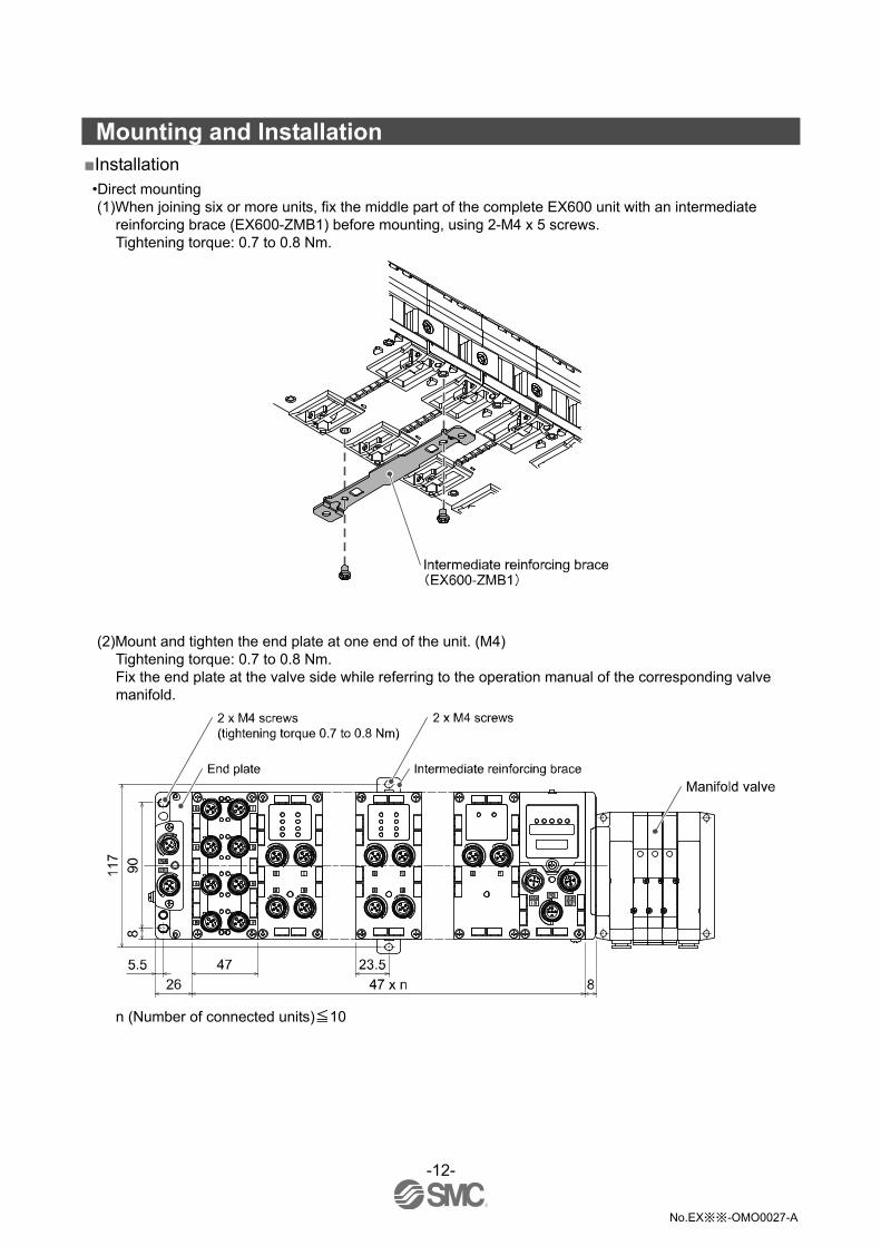
Mounting and Installation Installation •Direct mounting (1)When joining six or more units, fix the middle part of the complete EX600 unit with an intermediate
reinforcing brace (EX600-ZMB1) before mounting, using 2-M4 x 5 screws. Tightening torque: 0.7 to 0.8 Nm.
(2)Mount and tighten the end plate at one end of the unit. (M4) Tightening torque: 0.7 to 0.8 Nm. Fix the end plate at the valve side while referring to the operation manual of the corresponding valve manifold.
n (Number of connected units)≦10

-13-
No.EX※※-OMO0027-A
•DIN rail mounting (Not available for SY series valves. Refer to the SY catalog.) (1)When joining six or more units, fix the middle part of the complete EX600 unit with an intermediate
reinforcing brace (EX600-ZMB2) before mounting, using 2-M4 x 6 screws. Tightening torque: 0.7 to 0.8 Nm.
(2)Mount the end plate bracket (EX600-ZMA2) to the end plate at the opposite end to the valves, using 2-M4 x 14 screws. Tightening torque: 0.7 to 0.8 Nm.
(3)Hook the DIN rail mounting groove on to the DIN rail. (4)Press the manifold using its side hooked to the DIN rail as a fulcrum until the manifold is locked. (5)Fix the manifold by tightening the DIN rail fixing screws of the EX600-ZMA2. (M4 x 20)
Tightening torque: 0.7 to 0.8 Nm. The tightening torque at the valve side depends on the valve type. Refer to the operation manual of the corresponding valve manifold.

-14-
No.EX※※-OMO0027-A
Wiring •Connect the M12 connector cable. The M12 SPEEDCON connector connection method is explained below. (1)Align mark B on the metal bracket of the cable connector (plug) with mark A. (2)Align with mark C on the unit and insert the connector vertically.
If they are not aligned, the connector cannot be connected correctly. (3)When mark B has been turned 180 degrees (1/2 turn), wiring is complete. Confirm that the connection is
not loose. If turned too far, it will become difficult to remove the connector.
(1) (2) (3)
•Mounting the marker The signal name of the input or output devices and unit address can be written on the marker, and can be installed on each unit. Mount the marker (EX600-ZT1) into the marker groove as required.

-15-
No.EX※※-OMO0027-A
SI unit Model Indication and How to Order
EX600-S
SI unit Polarity of output
Symbol Content
Protocol 1 PNP (-common)
Symbol Content 2 NPN (+common)
EC EtherCAT
Summary of Product parts
No. Description Function
1 Status display LED Displays the status of the unit.
2 Display cover Open to access the setting switches.
3 Display cover screw Screw to open the display cover.
4 Connector (BUS OUT) Connector for fieldbus outputs.
5 Marker groove Groove for an identification marker.
6 Connector (PCI) Connector for Handheld Terminal.
7 Valve plate mounting hole Holes for fixing the valve plate.
8 Valve plate mounting groove Groove for mounting the valve plate.
9 Joint bracket Bracket for joining to adjacent units.
10 Unit connector (Plug) Connector for signals and power supplies to adjacent units.
11 Connector (BUS IN) Connector for fieldbus inputs.
12 Seal cap (2 pcs.) Fitted to unused connectors. (BUS OUT and PCI)
: The Handheld Terminal have to use EX600-HT1A. (EX600-HT1 cannot be used.)

-16-
No.EX※※-OMO0027-A
Mounting and Installation Wiring
•Connector pin assignment
Configuration
BUS IN BUS OUT Pin number Signal name
1 TD+
2 RD+
3 TD-
4 RD-
Precautions for handling
Be sure to fit a seal cap on any unused connectors. Proper use of the seal cap enables the enclosure to achieve IP67 specification.
-17-
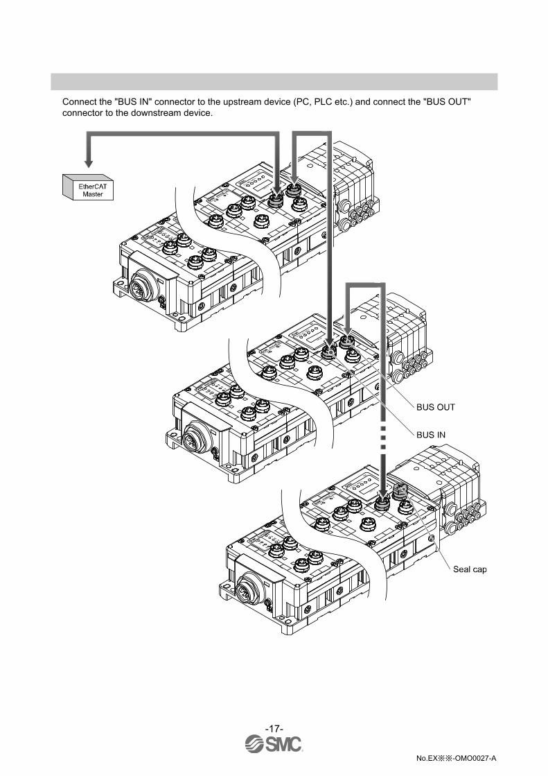
No.EX※※-OMO0027-A
Connect the "BUS IN" connector to the upstream device (PC, PLC etc.) and connect the "BUS OUT" connector to the downstream device.
-18-
No.EX※※-OMO0027-A
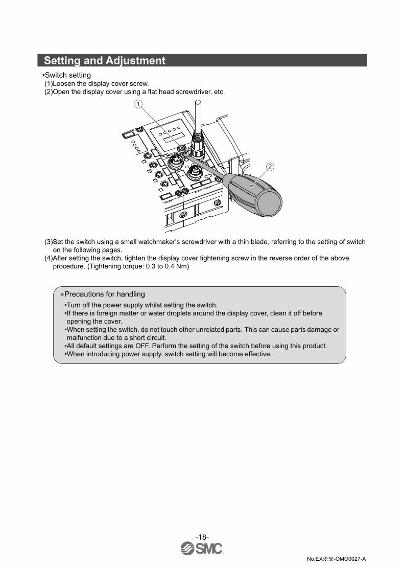
Setting and Adjustment •Switch setting (1)Loosen the display cover screw. (2)Open the display cover using a flat head screwdriver, etc.
(3)Set the switch using a small watchmaker's screwdriver with a thin blade, referring to the setting of switch on the following pages.
(4)After setting the switch, tighten the display cover tightening screw in the reverse order of the above procedure. (Tightening torque: 0.3 to 0.4 Nm)
Precautions for handling
•Turn off the power supply whilst setting the switch. •If there is foreign matter or water droplets around the display cover, clean it off before opening the cover.
•When setting the switch, do not touch other unrelated parts. This can cause parts damage or malfunction due to a short circuit.
•All default settings are OFF. Perform the setting of the switch before using this product. •When introducing power supply, switch setting will become effective.
-19-
No.EX※※-OMO0027-A
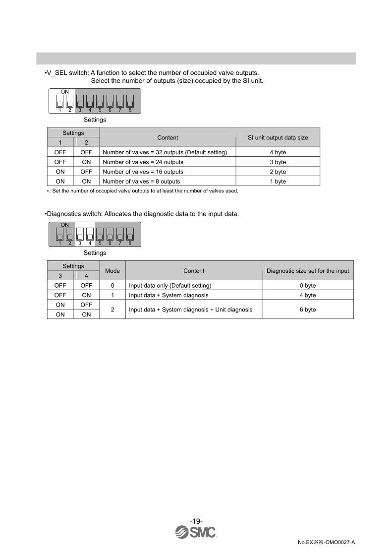
•V_SEL switch: A function to select the number of occupied valve outputs.
Select the number of outputs (size) occupied by the SI unit.
Settings
1 2 Content SI unit output data size
OFF OFF Number of valves = 32 outputs (Default setting) 4 byte
OFF ON Number of valves = 24 outputs 3 byte
ON OFF Number of valves = 16 outputs 2 byte
ON ON Number of valves = 8 outputs 1 byte
: Set the number of occupied valve outputs to at least the number of valves used.
•Diagnostics switch: Allocates the diagnostic data to the input data.
Settings
3 4 Mode Content Diagnostic size set for the input
OFF OFF 0 Input data only (Default setting) 0 byte
OFF ON 1 Input data + System diagnosis 4 byte
ON OFF
ON ON 2 Input data + System diagnosis + Unit diagnosis 6 byte

-20-
No.EX※※-OMO0027-A
•HOLD/CLEAR switch: Sets the output status when the fieldbus has a communication error or is in idle
state.
Settings
5 Content
OFF Output is OFF. (Default setting)
ON Holds the output.
: Refer to "Parameter Setting" (page 40), for the further details.
: A communication error refers to the SI unit, which is in interrupted communication state. Idle refers to the SI unit operation mode,
which is either in the default, pre-operational or safe operational modes.
•Configuration memory switch: When the manifold configuration memory switch is set ON and the power supply is switched ON, the system will compare the stored configuration with the manifold configuration. If the configuration is different, diagnostic error will be generated.
Settings
6 Content
OFF Normal operation mode (Default setting)
ON Configuration memory mode
•Timing to memorize the configuration When power supply for control and input is turned on, with the switch above turned OFF.
•Timing to compare the configuration When power supply for control and input is turned on, with the switch above turned ON.
Precautions for handling
•Handle the switch with care. Excessive force can break the switch. •7, 8 of the Settings switch are not used.

-21-
No.EX※※-OMO0027-A
LED Display The status display LED displays the power supply and communication status. Various kinds of status can be checked as follows:
Content
L/A IN Displays the communication status of the BUS IN side.
L/A OUT Displays the communication status of the BUS OUT side.
Display Content
ST(M) Displays the diagnostic status of the unit.
PWR Displays the status of the power supply voltage for control and input.
PWR(V) Displays the status of the power supply voltage for outputs.
RUN Displays the module status.
ERR Displays the network status.
•SI unit common status
LED display Content
OFF.
The power supply for control and input is OFF.
Green LEDs are ON.
The unit is in normal operation.
Red ST(M) LED is ON.
A component failure inside the SI unit.
Red PWR LED is ON.
The power supply voltage for control and input is abnormal.
Red PWR(V) LED is ON.
The power supply voltage for outputs is abnormal.
Green ST(M) LED is flashing.
A unit other than the SI unit has been detected.
Red ST(M) LED is flashing.
Either of the following conditions: •The valve ON/OFF counter has exceeded the set value. •The valve is short circuited or disconnected.
Red/Green ST(M) LED is flashing alternately.
Either of the following conditions: •Connection error between units has occurred. •Configuration memory error has occurred.

-22-
No.EX※※-OMO0027-A
•EtherCAT status
LED display LED state Content
OFF Initialized status
Flash Pre-operational status
Single Flash Safe operational status
(Green) ON Operational status
OFF No communication error
Flash Communication setup error (Red) Double Flash Communication error (application watchdog timeout)
OFF BUS IN side : No Link, No Activity
ON BUS IN side : Link, No Activity (Green) Flickering BUS IN side : Link, Activity
OFF BUS OUT side: No Link, No Activity
ON BUS OUT side: Link, No Activity (Green) Flickering BUS OUT side: Link, Activity
: Refer to the table below for the LED state.
Flickering
Flashing
Single Flash
Double Flash

-23-
No.EX※※-OMO0027-A
Specification Specifications
Model EX600-SEC1 EX600-SEC2
Protocol EtherCAT (Conformance Test Record V.1.2)
Communication speed 100 Mbps
Com
mun
icat
ion
Occupied area (Number of inputs/outputs)
(512 inputs/512 outputs) Max.
Internal current consumption (The power supply for control and input)
100 mA or less
Polarity of output PNP (-common) NPN (+common)
Number of Outputs 32 outputs (8/16/24/32 outputs selectable)
Connected load 24 VDC 1.5 W (SMC) solenoid valve with circuit protection of surge voltage
Power supply 24 VDC 2 A
Output condition at the time of communication error
HOLD/CLEAR/Force ON
Out
put
Protective function Short circuit protection
Enclosure IP67 (With manifold assembled) 1
Operating temperature range -10 to 50 oC 2
Storage temperature range -20 to 60 oC
Operating humidity range 35 to 85%R.H. (No condensation)
Withstand voltage 500 VAC for 1 minute between external terminals and F.E.
Insulation resistance 500 VDC, 10 MΩ or more between external terminals and F.E.
Env
ironm
ent
Pollution degree For use in Pollution Degree 3 Environment (UL508)
Standard CE, UL(CSA), RoHS
Weight 300 g
1: All unused connectors must have a seal cap fitted.
2: The UL compliant temperature is 0 to 50 oC.

-24-
No.EX※※-OMO0027-A
Dimensions (in mm)

-25-
No.EX※※-OMO0027-A
End plate Model Indication and How to Order
EX600-ED -
End plate at D side Mounting method
Symbol Content
Connector Nil No DIN rail bracket
Symbol Content 2 With DIN rail bracket
2 M12 (5 pin) 3 With DIN rail bracket (Specified for SY series)
3 7/8 inch (5 pin)
Summary of Product parts
•EX600-ED2- •EX600-ED3-
No. Description Function
1 Power connector Connector for power supply to SI unit and I/O unit.
2 Fixing hole for direct mounting Holes for direct mounting.
3 DIN rail fixing hole Holes for fix DIN rail mounting.
4 F.E. terminal Functional Earth terminal - must be connected directly to system earth (ground).
5 Connector (Not used) Unused connector. Do not remove seal cap.
: Individual grounding should be provided close to the product with a short cable.
-26-
No.EX※※-OMO0027-A
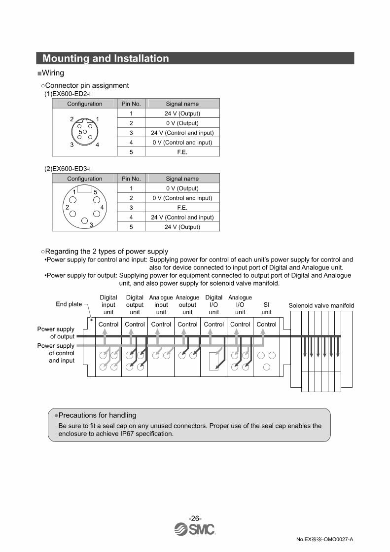
Mounting and Installation Wiring
Connector pin assignment (1)EX600-ED2-
Configuration Pin No. Signal name
1 24 V (Output)
2 0 V (Output)
3 24 V (Control and input)
4 0 V (Control and input) 5 F.E.
(2)EX600-ED3-
Configuration Pin No. Signal name
1 0 V (Output)
2 0 V (Control and input)
3 F.E.
4 24 V (Control and input)
5 24 V (Output)
Regarding the 2 types of power supply •Power supply for control and input: Supplying power for control of each unit’s power supply for control and
also for device connected to input port of Digital and Analogue unit. •Power supply for output: Supplying power for equipment connected to output port of Digital and Analogue
unit, and also power supply for solenoid valve manifold.
Precautions for handling
Be sure to fit a seal cap on any unused connectors. Proper use of the seal cap enables the enclosure to achieve IP67 specification.

-27-
No.EX※※-OMO0027-A
Specification Specifications
Model EX600-ED2- EX600-ED3-
Power connector M12 (5 pin) Plug 7/8 inch (5 pin) Plug
Power supply (Control and input)
24 VDC ±10% Class2, 2 A 24 VDC ±10%, 8 A
Pow
er
Power supply (Output) 24 VDC +10/-5% Class2, 2 A 24 VDC +10/-5%, 8 A
Enclosure IP67 (With manifold assembled) 1
Operating temperature range -10 to 50 oC (Max. surrounding air temperature rating: 50 oC) 2
Storage temperature range -20 to 60 oC
Operating humidity range 35 to 85%R.H. (No condensation)
Withstand voltage 500 VAC for 1 minute between external terminals and F.E.
Insulation resistance 500 VDC, 10 M min. between external terminals and F.E.
Env
ironm
ent
Pollution degree For use in Pollution Degree 3 Environment (UL508)
Standard CE, UL(CSA), RoHS
Weight 170 g 175 g
1: All unused connectors must have a seal cap fitted.
2: The UL agreement temperature is 0 to 50 oC.
Dimensions (in mm)
•EX600-ED2-

-28-
No.EX※※-OMO0027-A
•EX600-ED3-

-29-
No.EX※※-OMO0027-A
Maintenance Turn off the power supply, stop the supplied air, exhaust the residual pressure and verify the release of air before performing maintenance.
Cleaning method Use a soft cloth to remove stains. For heavy stains, use a cloth soaked with diluted neutral detergent and fully squeezed, then wipe up the stains again with a dry cloth. Do not use solvents such as benzene, thinner etc. to clean each unit.
Inspection item Content of inspection
Connector/Electric wiring Connect properly if the connection is loose.
Seal cap Tighten properly if the connection is loose.
Thread for mounting and installation
If the thread is loose, re-tighten it to the specified torque.
Connection cables If the cable is broken or any other abnormality is confirmed by appearance, replace the cable with a new one.
Supply source voltage Check if source voltage within the specification range (24 VDC ±10%) is supplied.
How to reset the product for power cut or forcible de-energizing Supply power to the product. The output status just before the power failure is not maintained when power supply is recovered. Start operation after confirming safety of the entire equipment.
-30-
No.EX※※-OMO0027-A
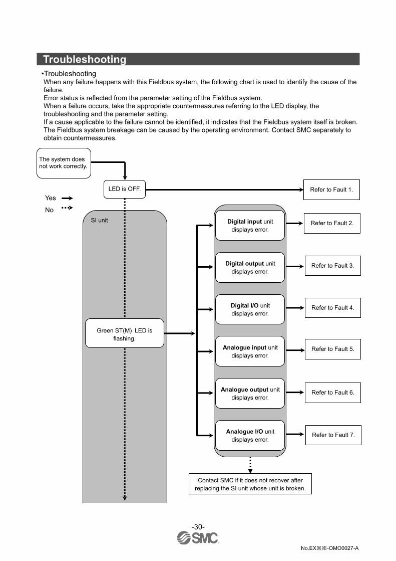
Troubleshooting
•Troubleshooting When any failure happens with this Fieldbus system, the following chart is used to identify the cause of the failure. Error status is reflected from the parameter setting of the Fieldbus system. When a failure occurs, take the appropriate countermeasures referring to the LED display, the troubleshooting and the parameter setting. If a cause applicable to the failure cannot be identified, it indicates that the Fieldbus system itself is broken. The Fieldbus system breakage can be caused by the operating environment. Contact SMC separately to obtain countermeasures.
Yes
No
The system does not work correctly.
LED is OFF.
Digital input unit displays error.
Digital output unit displays error.
Digital I/O unit displays error.
Analogue input unit displays error.
Analogue output unit displays error.
Analogue I/O unit displays error.
Contact SMC if it does not recover after replacing the SI unit whose unit is broken.
SI unit
Green ST(M) LED is flashing.
Refer to Fault 1.
Refer to Fault 2.
Refer to Fault 3.
Refer to Fault 4.
Refer to Fault 5.
Refer to Fault 6.
Refer to Fault 7.

-31-
No.EX※※-OMO0027-A
Green RUN LED is not ON.
Green L/A IN or L/A OUT LED is not flashing.
Red ERR LED is flashing.
Red ST(M) LED is ON. Or red/green ST(M)
LED is flashing alternately.
Red PWR or PWR(V) LED is ON.
SI unit
Red ST(M) LED is flashing. Refer to Fault 8.
Refer to Fault 9.
Refer to Fault 10.
The digital input or output device does not work
correctly.
The analogue input or output device does not
work correctly.
The valve does not work correctly.
Contact SMC.
Refer to Fault 14.
Refer to Fault 15.
Refer to Fault 16.
Refer to Fault 11.
Refer to Fault 12.
Refer to Fault 13.
-32-
No.EX※※-OMO0027-A
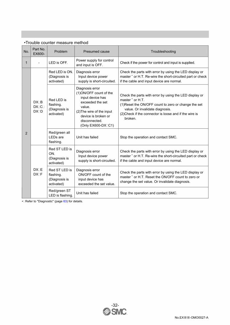
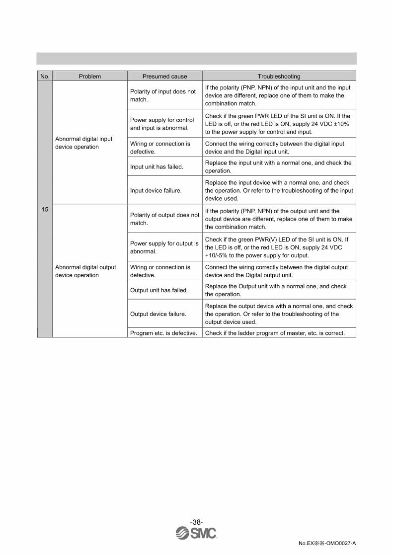
•Trouble counter measure method
No. Part No. EX600-
Problem Presumed cause Troubleshooting
1 - LED is OFF. Power supply for control and input is OFF.
Check if the power for control and input is supplied.
Red LED is ON. (Diagnosis is activated)
Diagnosis error Input device power supply is short-circuited.
Check the parts with error by using the LED display or master or H.T. Re-wire the short-circuited part or check if the cable and input device are normal.
Red LED is flashing. (Diagnosis is activated)
Diagnosis error (1)ON/OFF count of the
input device has exceeded the set value.
(2)The wire of the input device is broken or disconnected. (Only EX600-DX C1)
Check the parts with error by using the LED display or master or H.T. (1)Reset the ON/OFF count to zero or change the set
value. Or invalidate diagnosis. (2)Check if the connector is loose and if the wire is
broken.
DX B DX C DX D
Red/green all LEDs are flashing.
Unit has failed Stop the operation and contact SMC.
Red ST LED is ON. (Diagnosis is activated)
Diagnosis error Input device power supply is short-circuited.
Check the parts with error by using the LED display or master or H.T. Re-wire the short-circuited part or check if the cable and input device are normal.
Red ST LED is flashing. (Diagnosis is activated)
Diagnosis error ON/OFF count of the input device has exceeded the set value.
Check the parts with error by using the LED display or master or H.T. Reset the ON/OFF count to zero or change the set value. Or invalidate diagnosis.
2
DX E DX F
Red/green ST LED is flashing.
Unit has failed Stop the operation and contact SMC.
: Refer to "Diagnostic" (page 63) for details.

-33-
No.EX※※-OMO0027-A
No. Part No. EX600-
Problem Presumed cause Troubleshooting
Red LED is ON. (Diagnosis is activated)
Diagnosis error Output device is short-circuited.
Check the parts with error by using the LED display or master or H.T. Re-wire the short-circuited part or check if the cable and output device are normal.
Red LED is flashing. (Diagnosis is activated)
Diagnosis error (1)ON/OFF count of the
output device has exceeded the set value.
(2)The wire of the output device is broken or disconnected.
Check the parts with error by using the LED display or master or H.T. (1)Reset the ON/OFF count to zero or change the set
value. Or invalidate diagnosis. (2)Check if the connector is loose and if the wire is
broken.
DY B
Red/green all LEDs are flashing.
Unit has failed Stop the operation and contact SMC.
Red ST LED is ON. (Diagnosis is activated)
Diagnosis error Output device is short-circuited.
Check the parts with error by using the LED display or master or H.T. Re-wire the short-circuited part or check if the cable and output device are normal.
Red ST LED is flashing. (Diagnosis is activated)
Diagnosis error (1)ON/OFF count of the
output device has exceeded the set value.
(2)The wire of the output device is broken or disconnected.
Check the parts with error by using the LED display or master or H.T. (1)Reset the ON/OFF count to zero or change the set
value. Or invalidate diagnosis. (2)Check if the connector is loose and if the wire is
broken.
3
DY E DY F
Red/green ST LED is flashing.
Unit has failed Stop the operation and contact SMC.
Red ST(I) LED is ON. (Diagnosis is activated)
Diagnosis error Input device power supply is short-circuited.
Check the parts with error by using the LED display or master or H.T. Re-wire the short-circuited part or check if the cable and input device are normal.
Red ST(I) LED is flashing. (Diagnosis is activated)
Diagnosis error ON/OFF count of the input device has exceeded the set value.
Check the parts with error by using the LED display or master or H.T. Reset the ON/OFF count to zero or change the set value. Or invalidate diagnosis.
Red ST(O) LED is ON. (Diagnosis is activated)
Diagnosis error Output device is short-circuited.
Check the parts with error by using the LED display or master or H.T. Re-wire the short-circuited part or check if the cable and output device are normal.
Red ST(O) LED is flashing (Diagnosis is activated)
Diagnosis error (1)ON/OFF count of the
output device has exceeded the set value.
(2)The wire of the output device is broken or disconnected.
Check the parts with error by using the LED display or master or H.T. (1)Reset the ON/OFF count to zero or change the set
value. Or invalidate diagnosis. (2)Check if the connector is loose and if the wire is
broken.
4 DM E DM F
Red/green ST LED is flashing.
Unit has failed Stop the operation and contact SMC.
: Refer to "Diagnostic" (page 63) for details.
-34-
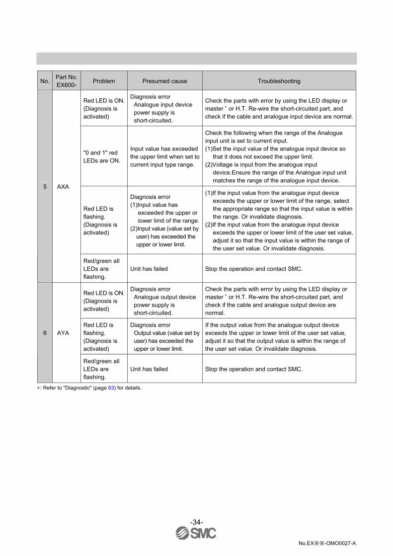
No.EX※※-OMO0027-A
No. Part No. EX600-
Problem Presumed cause Troubleshooting
Red LED is ON. (Diagnosis is activated)
Diagnosis error Analogue input device power supply is short-circuited.
Check the parts with error by using the LED display or master or H.T. Re-wire the short-circuited part, and check if the cable and analogue input device are normal.
"0 and 1" red LEDs are ON.
Input value has exceeded the upper limit when set to current input type range.
Check the following when the range of the Analogue input unit is set to current input. (1)Set the input value of the analogue input device so
that it does not exceed the upper limit. (2)Voltage is input from the analogue input
device.Ensure the range of the Analogue input unit matches the range of the analogue input device.
Red LED is flashing. (Diagnosis is activated)
Diagnosis error (1)Input value has
exceeded the upper or lower limit of the range.
(2)Input value (value set by user) has exceeded the upper or lower limit.
(1)If the input value from the analogue input device exceeds the upper or lower limit of the range, select the appropriate range so that the input value is within the range. Or invalidate diagnosis.
(2)If the input value from the analogue input device exceeds the upper or lower limit of the user set value, adjust it so that the input value is within the range of the user set value. Or invalidate diagnosis.
5 AXA
Red/green all LEDs are flashing.
Unit has failed Stop the operation and contact SMC.
Red LED is ON. (Diagnosis is activated)
Diagnosis error Analogue output device power supply is short-circuited.
Check the parts with error by using the LED display or master or H.T. Re-wire the short-circuited part, and check if the cable and analogue output device are normal.
Red LED is flashing. (Diagnosis is activated)
Diagnosis error Output value (value set by user) has exceeded the upper or lower limit.
If the output value from the analogue output device exceeds the upper or lower limit of the user set value, adjust it so that the output value is within the range of the user set value. Or invalidate diagnosis.
6 AYA
Red/green all LEDs are flashing.
Unit has failed Stop the operation and contact SMC.
: Refer to "Diagnostic" (page 63) for details.
-35-
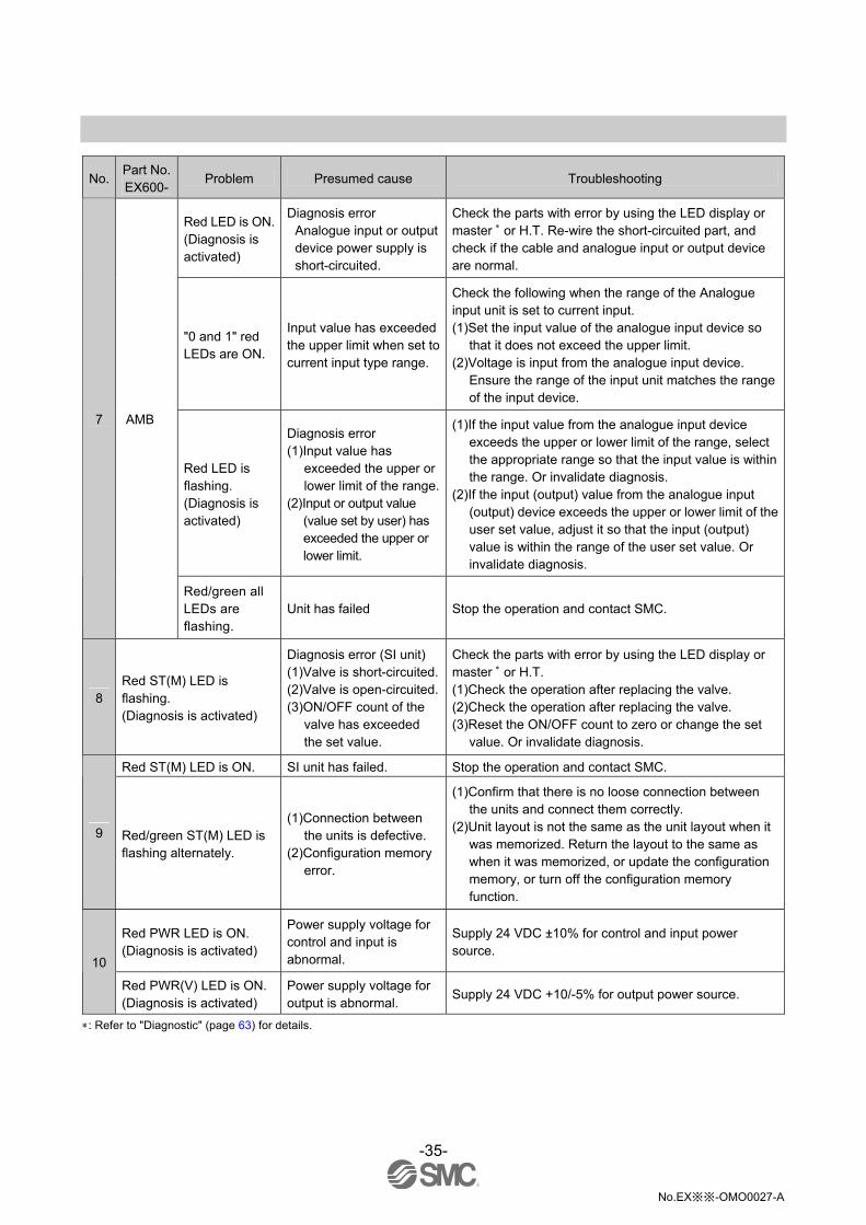
No.EX※※-OMO0027-A
No. Part No. EX600-
Problem Presumed cause Troubleshooting
Red LED is ON. (Diagnosis is activated)
Diagnosis error Analogue input or output device power supply is short-circuited.
Check the parts with error by using the LED display or master or H.T. Re-wire the short-circuited part, and check if the cable and analogue input or output device are normal.
"0 and 1" red LEDs are ON.
Input value has exceeded the upper limit when set to current input type range.
Check the following when the range of the Analogue input unit is set to current input. (1)Set the input value of the analogue input device so
that it does not exceed the upper limit. (2)Voltage is input from the analogue input device.
Ensure the range of the input unit matches the range of the input device.
Red LED is flashing. (Diagnosis is activated)
Diagnosis error (1)Input value has
exceeded the upper or lower limit of the range.
(2)Input or output value (value set by user) has exceeded the upper or lower limit.
(1)If the input value from the analogue input device exceeds the upper or lower limit of the range, select the appropriate range so that the input value is within the range. Or invalidate diagnosis.
(2)If the input (output) value from the analogue input (output) device exceeds the upper or lower limit of the user set value, adjust it so that the input (output) value is within the range of the user set value. Or invalidate diagnosis.
7 AMB
Red/green all LEDs are flashing.
Unit has failed Stop the operation and contact SMC.
8 Red ST(M) LED is flashing. (Diagnosis is activated)
Diagnosis error (SI unit) (1)Valve is short-circuited.(2)Valve is open-circuited.(3)ON/OFF count of the
valve has exceeded the set value.
Check the parts with error by using the LED display or master or H.T. (1)Check the operation after replacing the valve. (2)Check the operation after replacing the valve. (3)Reset the ON/OFF count to zero or change the set
value. Or invalidate diagnosis.
Red ST(M) LED is ON. SI unit has failed. Stop the operation and contact SMC.
9 Red/green ST(M) LED is flashing alternately.
(1)Connection between the units is defective.
(2)Configuration memory error.
(1)Confirm that there is no loose connection between the units and connect them correctly.
(2)Unit layout is not the same as the unit layout when it was memorized. Return the layout to the same as when it was memorized, or update the configuration memory, or turn off the configuration memory function.
Red PWR LED is ON. (Diagnosis is activated)
Power supply voltage for control and input is abnormal.
Supply 24 VDC ±10% for control and input power source.
10
Red PWR(V) LED is ON. (Diagnosis is activated)
Power supply voltage for output is abnormal.
Supply 24 VDC +10/-5% for output power source.
: Refer to "Diagnostic" (page 63) for details.

-36-
No.EX※※-OMO0027-A
No. Problem Presumed cause Troubleshooting
L/A IN and L/A OUT LEDs are OFF.
LINK has not yet been established.
Check the following and restart. (1)Check if the power is supplied to the EtherCAT device
one level above. (When L/A IN LED is OFF.) (2)Check that the connectors of L/A IN and L/A OUT
communication cables are connected and there are no broken wires.
(3)Keep noise sources away from the communication cable.
: The L/A OUT LED will be OFF if the BUS OUT connector is
not used. 11
L/A IN and L/A OUT Green LED is ON.
LINK is established but data has not been received.
Check the following and restart. (1)Check the master condition and run the master. (2)Check whether the L/A LEDs of the EtherCAT devices
two or more levels above are off. If so, please check if the power is supplied.
(3)Check that the communication connector is not loose and there are no broken wires.
(4)Keep noise sources away from the communication cable.
ERR LED is Double flashing.
Communication error (Application watchdog timeout)
Check the following and restart. (1)Check the master condition and run the master. (2)Check if the power is supplied to the EtherCAT
device. (3)Check that the communication connector is not loose
and there are no broken wires.
12
ERR LED is flashing. Communication setup error
Check the master configuration and the system structure.
RUN LED is OFF. SI unit is initialized. Download an appropriate XML file from SMC website and perform configuration.
RUN LED is flashing. Pre-operational status Check the master condition and RUN the master. 13
RUN LED is single flashing.
Safe operational status Check the master condition and RUN the master.
: Refer to page 21 "LED display" for details of LED status.

-37-
No.EX※※-OMO0027-A
No. Problem Presumed cause Troubleshooting
The number of connected valves is larger than the number of occupied valve outputs.
When the number of occupied valves of the V_SEL switch is smaller than the number of connected valves, set the switch so that the number of occupied valves is not smaller than the number of valves to be used.
Abnormality with program, etc.
Check if the ladder program of master, etc. is correct.
Abnormal power supply for output.
Check if the green PWR(V) LED of the SI unit is ON. If the LED is off, or the red LED is ON, supply 24 VDC +10/-5% to the power supply for output.
Connection between SI unit and manifold valve is defective.
Check the connectors between the SI unit and manifold valve are not damaged, such as bent pins, and connect them correctly.
Polarity of output does not match.
IF the polarity of the SI unit and the valve are different, replace one of them to make the combination match. •EX600-SEC1 (PNP output) -common type valve
•EX600-SEC2 (NPN output) +common type valve
SI unit has failed. Replace the SI unit with a normal one, and check the operation.
14 Abnormal valve operation
Valve failure. Replace the valve with a normal one, and check the operation. Or refer to the troubleshooting of the valve used.
-38-
No.EX※※-OMO0027-A
No. Problem Presumed cause Troubleshooting
Polarity of input does not match.
If the polarity (PNP, NPN) of the input unit and the input device are different, replace one of them to make the combination match.
Power supply for control and input is abnormal.
Check if the green PWR LED of the SI unit is ON. If the LED is off, or the red LED is ON, supply 24 VDC ±10% to the power supply for control and input.
Wiring or connection is defective.
Connect the wiring correctly between the digital input device and the Digital input unit.
Input unit has failed. Replace the input unit with a normal one, and check the operation.
Abnormal digital input device operation
Input device failure. Replace the input device with a normal one, and check the operation. Or refer to the troubleshooting of the input device used.
Polarity of output does not match.
If the polarity (PNP, NPN) of the output unit and the output device are different, replace one of them to make the combination match.
Power supply for output is abnormal.
Check if the green PWR(V) LED of the SI unit is ON. If the LED is off, or the red LED is ON, supply 24 VDC +10/-5% to the power supply for output.
Wiring or connection is defective.
Connect the wiring correctly between the digital output device and the Digital output unit.
Output unit has failed. Replace the Output unit with a normal one, and check the operation.
Output device failure. Replace the output device with a normal one, and check the operation. Or refer to the troubleshooting of the output device used.
15
Abnormal digital output device operation
Program etc. is defective. Check if the ladder program of master, etc. is correct.

-39-
No.EX※※-OMO0027-A
No. Problem Presumed cause Troubleshooting
Power supply for control and input is abnormal.
Check if the green PWR LED of the SI unit is ON. If the LED is off, or the red LED is ON, supply 24 VDC ±10% to the power supply for control and input.
Analogue input signal range setting failure.
Check the analogue input device specification, and set the input signal range which satisfies the specification.
Analogue data format does not match.
Check whether the data format of the Analogue input unit is properly set.
Wiring or connection is defective.
Connect the wiring correctly between the analogue input device and the Analogue input unit.
Analogue input unit has failed.
Replace the Analogue input unit with a normal one, and check the operation.
Abnormal analogue input device operation
Analogue input device failure.
Replace the analogue input device with a normal one, and check the operation. Or refer to the troubleshooting of the analogue input device used.
Power supply for output is abnormal.
Check if the green PWR(V) LED of the SI unit is ON. If the LED is off, or the red LED is ON, supply 24 VDC +10/-5% to the power supply for output.
Analogue output signal range setting failure.
Check the analogue output device specification, and set the output signal range which satisfies the specification.
Analogue data format does not match.
Check whether the data format of the Analogue output unit is properly set.
Wiring or connection is defective.
Connect the wiring correctly between the analogue output device and the Analogue output unit.
Analogue output unit has failed.
Replace the Analogue output unit with a normal one, and check the operation.
Analogue output device failure.
Replace the analogue output device with a normal one, and check the operation. Or refer to the troubleshooting of the analogue output device used.
16
Abnormal analogue output device operation
Program etc. is defective. Check if the ladder program of master, etc. is correct.

-40-
No.EX※※-OMO0027-A
Parameter Setting The product has parameters that can be set for the system, each unit or each channel. The parameters can be changed using the PLC and handheld terminal. There is no order of precedence of the PLC and handheld terminal. The latest parameter settings are used.
Parameter definition and setting •System parameters
Parameter setting
No. Parameter
(H.T. Symbol) Definition Item Content
Default setting By
Ether CAT
By H.T.
Switch
Setting by SI unit switch becomes valid. OFF/Hold/Forced ON can be set per channel
1 Hold/Clear priority setting (Hold/Clear)
Switch the setting of the output during communication error or communication idling to follow the setting of the SI unit or the parameters.
Handheld
Setting by parameters or the H.T. becomes valid. OFF/Hold/Forced ON can be set per channel.
Precautions for handling
•Changing parameters with the H.T. does not change the parameter settings in the PLC. •If parameters are downloaded from the configuration to the PLC after changing parameters with the H.T., parameters will be changed to those which are set by the configuration. Therefore, set parameters by PLC if the parameters can be changed by both PLC and H.T.
•The H.T. have to use EX600-HT1A. (EX600-HT1 cannot be used.)
-41-
No.EX※※-OMO0027-A
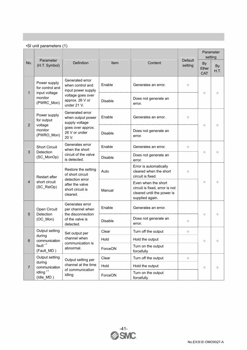
•SI unit parameters (1)
Parameter setting
No. Parameter
(H.T. Symbol) Definition Item Content
Default setting By
Ether CAT
By H.T.
Enable Generates an error.
1
Power supply for control and input voltage monitor (PWRC_Mon)
Generated error when control and input power supply voltage goes over approx. 26 V or under 21 V.
Disable Does not generate an error.
Enable Generates an error.
2
Power supply for output voltage monitor (PWRO_Mon)
Generated error when output power supply voltage goes over approx. 26 V or under 20 V.
Disable Does not generate an error.
Enable Generates an error.
3 Short Circuit Detection (SC_MonOp)
Generates error when the short circuit of the valve is detected. Disable
Does not generate an error.
Auto Error is automatically cleared when the short circuit is fixed.
4 Restart after short circuit (SC_RstOp)
Restore the setting of short circuit detection error after the valve short circuit is cleared.
Manual
Even when the short circuit is fixed, error is not cleared until the power is supplied again.
Enable Generates an error.
5 Open Circuit Detection (OC_Mon)
Generates error per channel when the disconnection of the valve is detected.
Disable Does not generate an error.
Clear Turn off the output
Hold Hold the output 6
Output setting during communication fault 1 (Fault_MD )
Set output per channel when communication is abnormal. ForceON
Turn on the output forcefully
Clear Turn off the output
Hold Hold the output 7
Output setting during communication idling 1 (Idle_MD )
Output setting per channel at the time of communication idling ForceON
Turn on the output forcefully

-42-
No.EX※※-OMO0027-A
•SI unit parameters (2)
Parameter setting
No. Parameter
(H.T. Symbol) Definition Item Content
Default setting By
Ether CAT
By H.T.
Enable Generates an error. Val: 1 to 65000 3
8
Valve ON/OFF counter (Counter)
Memorizes the number of times the valve is ON. Generates error per channel when the operation count exceeds the set value. 2
Disable Does not generate an error.
1: This master is valid only when "Hold/Clear priority" of the system parameter is set to Handheld.
: The count is memorized every 30 seconds per channel. When the power supply is turned on again, counting starts from the last value
memorized.
3: Times for setting is set value x1000 times.

-43-
No.EX※※-OMO0027-A
•Digital input unit parameters
Parameter setting
No. Parameter
(H.T. Symbol) Definition Item Content
Default setting By
Ether CAT
By H.T.
Enable Generates an error.
1
The power supply short circuit detection for control and input (SC_MonSs)
Generates error per unit when the short circuit of the power supply for the input device is detected.
Disable Does not generate an error.
Enable Generates an error.
2 Open circuit detection 1 (OC_Mon)
Generates error per channel when the disconnection of the input device is detected. 2
Disable Does not generate an error.
Enable Ignores excess current.
3 Inrush current filter (Inrush)
Ignores excess current per unit for 100 msec. after inrush.
Disable Does not ignore excess current.
0.1 ms 1.0 ms
10 ms 4
Input filtering time (Filter_T)
Sets the time to ignore the input signal change per unit. 20 ms
Selects the time for filtering.
1.0 ms
1.0ms 15 ms
100 ms 5
Input extension time (SigExt_T)
Sets the time to hold the input signal per unit.
200 ms
Selects the time to hold the input signal.
15 ms
Enable Generates an error. Val: 1 to 65000 4
6
Channel ON/OFF counter (Counter)
Memorizes the number of times the input device is ON. Generates error per channel when the operation count exceeds the set value. 3
Disable Does not generate an error.
1: Disconnection detection is a parameter only available for Digital unit (EX600-DXPC1, EX600-DXNC1) with disconnection detection.
2: 2-wire type input equipment cannot be correctly detected if its leakage current is 0.5 mA or less while the equipment is in the OFF state
(reed sensor, etc.).
Ensure that all input equipment used has a leakage current above 0.5 mA in the OFF state.
3-wire type input equipment cannot be correctly detected if its current consumption is 0.5mA or less.
The open circuit of input signals cannot be detected.
3: The count is memorized every hour. When the power supply is turned on again, counting starts from the last value memorized.
4: Times for setting is set value x1000 times.

-44-
No.EX※※-OMO0027-A
•Digital output unit parameters
Parameter setting
No. Parameter
(H.T. Symbol) Definition Item Content
Default setting By
Ether CAT
By H.T.
Enable Generates an error.
1
Output load short circuit detection (SC_MonOp)
Generates error per unit when the short circuit of the output device is detected. 1
Disable Does not generate an error.
Auto Error is automatically cleared when the short circuit is fixed.
2
Restart after output load short circuit (SC_RstOp)
Restore the setting of short circuit detection error per unit after the output device short circuit is cleared.
Manual
Even when the short circuit is fixed, error is not cleared until the power is supplied again.
Enable Generates an error.
3 Open circuit detection (OC_Mon)
Generates error per channel when the disconnection of the output device is detected.
Disable Does not generate an error.
Clear Turn off the output
Hold Hold the output 4
Output setting during communication fault 2 (Fault_MD)
Set output per channel when communication is abnormal. ForceON
Turn on the output forcefully
Clear Turn off the output
Hold Hold the output 5
Output setting during communication idling 2 (Idle_MD)
Set output per channel during communication idling. ForceON
Turn on the output forcefully
Enable Generates an error. Val: 1 to 65000 4
6
Output ON/OFF counter (Counter)
Memorizes the number of times the output device is ON. Generates error per channel when the operation count exceeds the set value. 3
Disable Does not generate an error.
1: Could be incorrectly recognized as short circuit depending on used load (ex.: lamp load). If detection is incorrect, disable the
parameter setting.
2: This master is valid only when "Hold/Clear priority" of the system parameter is set to Handheld.
: The count is memorized every hour. When the power supply is turned on again, counting starts from the last value memorized.
4: Times for setting is set value x1000 times.
-45-
No.EX※※-OMO0027-A
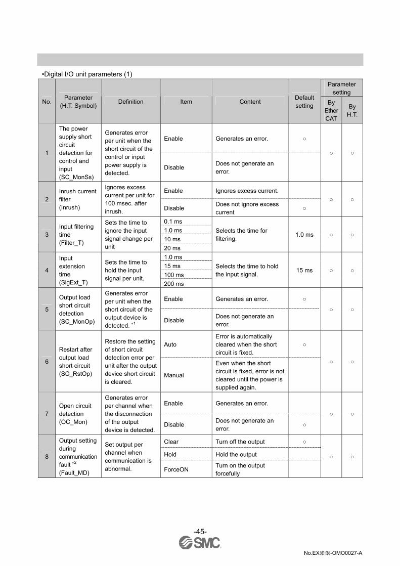
•Digital I/O unit parameters (1)
Parameter setting
No. Parameter
(H.T. Symbol) Definition Item Content
Default setting By
Ether CAT
By H.T.
Enable Generates an error.
1
The power supply short circuit detection for control and input (SC_MonSs)
Generates error per unit when the short circuit of the control or input power supply is detected.
Disable Does not generate an error.
Enable Ignores excess current.
2 Inrush current filter (Inrush)
Ignores excess current per unit for 100 msec. after inrush. Disable
Does not ignore excess current
0.1 ms
1.0 ms
10 ms 3
Input filtering time (Filter_T)
Sets the time to ignore the input signal change per unit 20 ms
Selects the time for filtering.
1.0 ms
1.0 ms
15 ms
100 ms 4
Input extension time (SigExt_T)
Sets the time to hold the input signal per unit.
200 ms
Selects the time to hold the input signal.
15 ms
Enable Generates an error.
5
Output load short circuit detection (SC_MonOp)
Generates error per unit when the short circuit of the output device is detected. 1
Disable Does not generate an error.
Auto Error is automatically cleared when the short circuit is fixed.
6
Restart after output load short circuit (SC_RstOp)
Restore the setting of short circuit detection error per unit after the output device short circuit is cleared.
Manual
Even when the short circuit is fixed, error is not cleared until the power is supplied again.
Enable Generates an error.
7 Open circuit detection (OC_Mon)
Generates error per channel when the disconnection of the output device is detected.
Disable Does not generate an error.
Clear Turn off the output
Hold Hold the output 8
Output setting during communication fault 2 (Fault_MD)
Set output per channel when communication is abnormal. ForceON
Turn on the output forcefully

-46-
No.EX※※-OMO0027-A
•Digital I/O unit parameters (2)
Parameter setting
No. Parameter
(H.T. Symbol) Definition Item Content
Default setting By
Ether CAT
By H.T.
Clear Turn off the output
Hold Hold the output 9
Output setting for communication idling 2 (Idle_MD)
Set output per channel during communication idling. ForceON
Turn on the output forcefully
Enable Generates an error. Val: 1 to 65000 4
10
Input or Output ON/OFF counter (Counter)
Memorizes the number of times the input or output device is ON. Generates error per channel when the operation count exceeds the set value. 3
Disable Does not generate an error.
1: Could be incorrectly recognized as short circuit depending on used load (ex.: lamp load). If detection is incorrect, disable the
parameter setting.
2: This master is valid only when "Hold/Clear priority" of the system parameter is set to Handheld.
3: The count is memorized every hour. When the power supply is turned on again, counting starts from the last value memorized.
4: Times for setting is set value x1000 times.

-47-
No.EX※※-OMO0027-A
•Analogue input unit parameters
Parameter setting
No. Parameter
(H.T. Symbol) Definition Item Content
Default setting By
Ether CAT
By H.T.
Enable Generates an error.
1
The power supply short circuit detection for the input device (SC_MonSs)
Generates error per unit when the short circuit of the power supply for the input device is detected.
Disable Does not generate an error.
-10..10 V -5..5 V
-20..20 mA
0..10 V
0..5 V
1..5 V
0..20 mA
2 Analogue input range (Range)
Set the analogue input device range per channel.
4..20 mA
Selects the analogue input range.
-10..10 V
Offset binary Offset binary.
Sign & Magnitude
Signed binary. 3 Analogue data format (D_Format)
Sets analogue data type which is output to master per unit. 2’s complement 2’s complement.
None None
2AVG 2 value average
4AVG 4 value average 4
Analogue average filter (Filter)
Sets analogue filtering time per channel. Sampling interval is approx. 2 sec. 8AVG 8 value average
Enable Generates an error.
5 Over range detection (Over_Rng)
Generates error per unit when the input value exceeds 0.5% of full span.
Disable Does not generate an error.
Enable Generates an error.
6 Under range detection (Undr_Rng)
Generates error per unit when the input value falls below 0.5% of full span.
Disable Does not generate an error.
Enable Generates an error. 1
7
User setting value upper limit error (Upr_Lmt)
Generates error per unit when the input value exceeds the set value.
Disable Does not generate an error.
Enable Generates an error. 1
8
User setting value lower limit error (Lwr_Lmt)
Generates error per channel when the input value falls below the set value.
Disable Does not generate an error.
1: Set value shall be set per analogue input range within settable range on the following page. When the analogue input range is changed,
check the set value and change it to an appropriate value.
For settings via EtherCAT, make sure to set the upper limit set value larger than the lower limit set value, as the setting is otherwise
invalid, although the setting may be set to "valid".

-48-
No.EX※※-OMO0027-A
Upper and lower setting limit of user setting Analogue input measurement range (Range) (Lwr_Lmt) (Upr_Lmt)
-10..10 V -10.50 to +10.45 V -10.45 to +10.50 V
-5..5 V - 5.25 to + 5.22 V - 5.22 to +5.25 V
-20..20 mA -21.00 to +20.90 mA -20.90 to +21.00 mA
0..10 V 0.00 to +10.45 V +0.05 to +10.50 V
0..5 V 0.00 to +5.22 V +0.03 to +5.25 V
1..5 V +0.75 to +5.22 V +0.78 to +5.25 V
0..20 mA 0.00 to +20.90 mA +0.10 to +21.00 mA
4..20 mA +3.00 to +20.90 mA +3.10 to +21.00 mA
-49-
No.EX※※-OMO0027-A
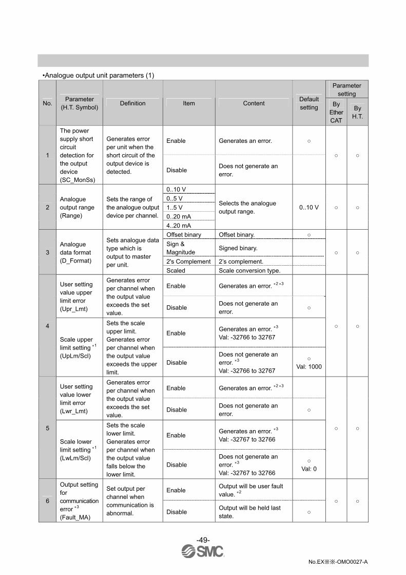
•Analogue output unit parameters (1)
Parameter setting
No. Parameter
(H.T. Symbol) Definition Item Content
Default setting By
Ether CAT
By H.T.
Enable Generates an error.
1
The power supply short circuit detection for the output device (SC_MonSs)
Generates error per unit when the short circuit of the output device is detected. Disable
Does not generate an error.
0..10 V
0..5 V
1..5 V
0..20 mA
2 Analogue output range (Range)
Sets the range of the analogue output device per channel.
4..20 mA
Selects the analogue output range.
0..10 V
Offset binary Offset binary.
Sign & Magnitude
Signed binary.
2's Complement 2’s complement.
3 Analogue data format (D_Format)
Sets analogue data type which is output to master per unit.
Scaled Scale conversion type.
Enable Generates an error. 2 3 User setting value upper limit error (Upr_Lmt)
Generates error per channel when the output value exceeds the set value.
Disable Does not generate an error.
Enable Generates an error. 3 Val: -32766 to 32767
4
Scale upper limit setting 1 (UpLm/Scl)
Sets the scale upper limit. Generates error per channel when the output value exceeds the upper limit.
Disable Does not generate an error. 3 Val: -32766 to 32767
Val: 1000
Enable Generates an error. 2 3 User setting value lower limit error (Lwr_Lmt)
Generates error per channel when the output value exceeds the set value.
Disable Does not generate an error.
Enable Generates an error. 3 Val: -32767 to 32766
5
Scale lower limit setting 1 (LwLm/Scl)
Sets the scale lower limit. Generates error per channel when the output value falls below the lower limit.
Disable Does not generate an error. 3 Val: -32767 to 32766
Val: 0
Enable Output will be user fault value. 2
6
Output setting for communication error 3 (Fault_MA)
Set output per channel when communication is abnormal. Disable
Output will be held last state.

-50-
No.EX※※-OMO0027-A
•Analogue output unit parameters (2)
Parameter setting
No. Parameter
(H.T. Symbol) Definition Item Content
Default setting By
Ether CAT
By H.T.
Enable Output will be user idle value. 2
7
Output setting for communication idling 4 (Idle_MA)
Set output per channel during communication idling. Disable
Output will be held last state.
1: When "Scaled" is selected as the analogue data format, the display of H.T. is switched from Upr_Lmt to UpLm/Scl, from Lwr_Lmt to
LwLm/Scl.
2: Set value shall be set per analogue input range within settable range in the table below.
When the analogue input range is changed, check the set value and change it to an appropriate value.
3: For settings of the user upper/lower limit or scale upper/lower limit via EtherCAT, make sure to set the upper limit set value larger than
the lower limit set value, as the setting is actually invalid if it is set with the upper limit set value is smaller than the lower limit set value,
although the setting in such condition is be set to be "valid".
4: This master is valid only when "Hold/Clear priority" of the system parameter is set to Handheld.
Upper and lower setting limit of user setting Analogue output measurement range
(Range) (Lwr_Lmt) (Upr_Lmt)
Settable range during communication error or idling
(Fault_MA) (Idle_MA)
0..10 V 0.00 to +10.45 V +0.05 to +10.50 V 0.00 to +10.50 V
0..5 V 0.00 to + 5.22 V +0.03 to +5.25 V 0.00 to +5.25 V
1..5 V +0.75 to +5.22 V +0.78 to +5.25 V +0.75 to +5.25 V
0..20 mA 0.00 to +20.90 mA +0.10 to +21.00 mA 0.00 to +21.00 mA
4..20 mA +3.00 to +20.90 mA +3.10 to +21.00 mA +3.00 to +21.00 mA
-51-
No.EX※※-OMO0027-A
•Analogue I/O unit parameters (1)
Parameter setting
No. Parameter
(H.T. Symbol) Definition Item Content
Default setting By
Ether CAT
By H.T.
Enable Generates an error.
1
The power supply short circuit detection for the input or output device (SC_MonSs)
Generates error per unit when the short circuit of the input device power supply or output device is detected.
Disable Does not generate an error.
0..10 V
0..5 V
1..5 V
0..20 mA
2
Analogue input or output range (Range)
Sets the analogue input or output device range per channel.
4..20 mA
Selects the analogue input or output range
1..5 V
Offset binary Offset binary.
Sign & Magnitude
Signed binary.
2s complement 2’s complement.
3 Analogue data format (D_Format)
Sets analogue data type which is output to master per unit.
Scaled Scale conversion type.
None None
2AVG 2 value average
4AVG 4 value average 4
Analogue average filter (Filter)
Sets analogue filtering time per channel. Sampling interval is approx. 2 sec. 8AVG 8 value average
Enable Generates an error.
5 Over range detection (Over_Rng)
Generates error per unit when the input value exceeds 0.5% of full span.
Disable Does not generate an error.
Enable Generates an error.
6 Under range detection (Undr_Rng)
Generates error per unit when the input value falls below 0.5% of full span.
Disable Does not generate an error.
Enable Generates an error. 2 3 User’s set value upper limit error (Upr_Lmt)
Generates error per channel when the input or output value exceeds the set value.
Disable Does not generate an error.
Enable Generates an error. 3 Val: -32766 to 32767
7
Scale upper limit setting 1 (UpLm/Scl)
Sets the scale upper limit. Generates error per channel when the input or output value exceeds the upper limit.
Disable Does not generated an error. 3 Val: -32766 to 32767
Val: 1000

-52-
No.EX※※-OMO0027-A
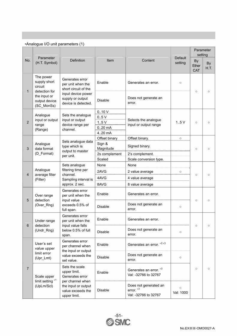
•Analogue I/O unit parameters (2)
Parameter setting
No. Parameter
(H.T. Symbol) Definition Item Content
Default setting By
Ether CAT
By H.T.
Enable Generates an error. 2 User’s set value lower limit error (Lwr_Lmt)
Generates error per channel when the input or output value falls below the lower limit.
Disable Does not generate an error.
Enable Generates an error. 3 Val: -32767 to 32766
8
Scale lower limit setting 1 (UpLm/Scl)
Sets the scale lower limit. Generates error per channel when the input or output value falls below the lower limit.
Disable Does not generate an error. 3 Val: -32767 to 32766
Val: 0
Enable Output will be user fault value. 2
9
Output setting for communication fault 3 (Fault_MA)
Set output per channel when communication is abnormal. Disable
Output will be held last state.
Enable Output will be user idle value. 2
10
Output setting for communication idling 4 (Idle_MA)
Sets output per channel during communication idling. Disable
Output will be held last state.
1: When "Scaled" is selected as the analogue data format, the display of H.T. is switched from Upr_Lmt to UpLm/Scl, from Lwr_Lmt to
LwLm/Scl.
2: Set value shall be set per analogue output range within settable range in the table below.
When the analogue output range is changed, check the set value and change it to an appropriate value.
3: For settings of the user upper/lower limit or scale upper/lower limit via EtherCAT, make sure to set the upper limit set value larger than
the lower limit set value, as the setting is, although the setting may be set to "valid".
4: This master is valid only when "Hold/Clear priority" of the system parameter is set to Handheld.
Upper and lower setting limit of user setting Analogue Input or output measurement range
(Range) (Lwr_Lmt) (Upr_Lmt)
Settable range during communication error or idling
(Fault_MA) (Idle_MA)
0..10 V 0.00 to +10.45 V +0.05 to +10.50 V 0.00 to +10.50 V
0..5 V 0.00 to +5.22 V +0.03 to +5.25 V 0.00 to +5.25 V
1..5 V +0.75 to +5.22 V +0.78 to +5.25 V +0.75 to +5.25 V
0..20 mA 0.00 to +20.90 mA +0.10 to +21.00 mA 0.00 to +21.00 mA
4..20 mA +3.00 to +20.90 mA +3.10 to +21.00 mA +3.00 to +21.00 mA
-53-
No.EX※※-OMO0027-A
Hardware Configuration The address is automatically recognized and allocated to the EtherCAT product during configuration. (There is no need for the user to set an address) Make sure to use the XML file for EX600 to perform configuration. XML file The XML file is required to configure the EX600. The file can be downloaded from the SMC website. •URL:http://www.smcworld.com Product Document → Instruction Manual
Setting using TwinCAT® System Manager The following describes how to connect the EX600 to a PC with TwinCAT® System Manager installed. Refer to the manual of TwinCAT® System Manager for details of the operating method.
•XML file installation (1)Copy the XML file for the EX600 to the following folder.
C:\TwinCAT\IO\EtherCAT (: This path is valid only when the folder for TwinCAT® System Manager is installed in the default folder location.)
(2) Start up the TwinCAT® System Manager. •Registration to the network When registering the EX600 on the network, there are two methods available, as follows. •On-line Auto Configuration •Off-line Manual Configuration

-54-
No.EX※※-OMO0027-A
On-line Auto Configuration •Connect the EX600 unit to the network and supply the power. •Right click the [I/O Devices] file, and then left click the [Scan Devices] file from the pop up menu.
•When the comment “Scan for boxes” appears, left click the [YES(Y)] button.

-55-
No.EX※※-OMO0027-A
•Once the scan is successfully completed, [Box 1(EX600-SEC)] is displayed as shown in the screen below. (example for when only one EX600-SEC is connected to the network.)
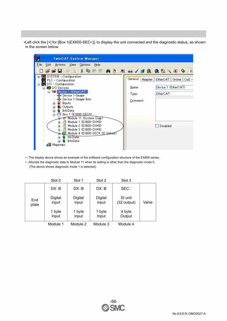
-56-
No.EX※※-OMO0027-A
•Left click the [+] for [Box 1(EX600-SEC)], to display the unit connected and the diagnostic status, as shown in the screen below.
: The display above shows an example of the software configuration structure of the EX600 series.
: Allocate the diagnostic data to Module 11 when its setting is other than the diagnostic mode 0.
(The above shows diagnostic mode 1 is selected)
Slot 0 Slot 1 Slot 2 Slot 3
End plate
DX B
Digital input
1 byte Input
DX B
Digital input
1 byte Input
DX B
Digital input
1 byte Input
SEC
SI unit (32 output)
4 byte Output
Valve
Module 1 Module 2 Module 3 Module 4
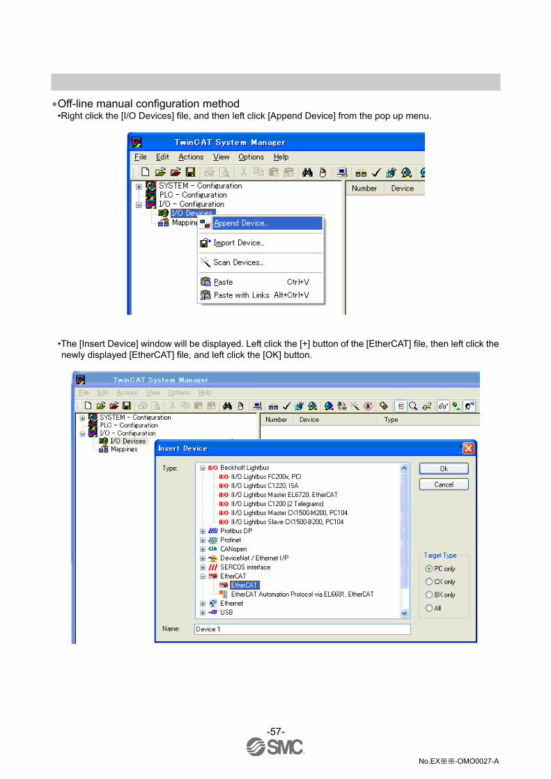
-57-
No.EX※※-OMO0027-A
Off-line manual configuration method •Right click the [I/O Devices] file, and then left click [Append Device] from the pop up menu.
•The [Insert Device] window will be displayed. Left click the [+] button of the [EtherCAT] file, then left click the newly displayed [EtherCAT] file, and left click the [OK] button.

-58-
No.EX※※-OMO0027-A
•[Device1(EtherCAT)] file will be added under the [I/O Devices]. Right click the [Device1(EtherCAT)] file, and then left click the [Box] file from the pop up menu.
•The [Insert EtherCAT Device] window will be displayed. Left click the [+] button of the [SMC Corporation] file, left click the [+] button of the [EX600 Series SI Unit], left click the [EX600-SEC*EtherCAT SI Unit] file, and then left click the [OK] button.

-59-
No.EX※※-OMO0027-A
•[Box1(EX600-SEC)] file will be added under the [Device1(EtherCAT)] file. Left click the [Box1(EX600-SEC)] file, and then left click the [Slots] tab on the right screen.
•When [Slot 0] in the Slot list on the left is selected, the product numbers of the EX600 series is displayed in the Module list in the right screen.

-60-
No.EX※※-OMO0027-A
•Left click the product number of the EX600 series that is connected to [Slot 0] from the Module list on the right.
•Left click the [<] button. The selected unit is allocated as [Module1] in the Slot list [Slot 0] on the left.

-61-
No.EX※※-OMO0027-A
•Similarly, allocate all of the I/O units, SI unit and diagnostic data (when the diagnostic data is specified.). •Supply power after connecting the product. Then, click [Reload I/O Devices] to set the device on-line.
: The display above shows an example of the software configuration structure of the EX600 series.
: Allocate the diagnostic data to Module 11 when its setting is other than the diagnostic mode 0.
(The above shows when diagnostic mode 1 is selected)
Slot 0 Slot 1 Slot 2 Slot 3
End plate
DX B
Digital output
1 byte Input
DX B
Digital output
1 byte Input
DX B
Digital output
1 byte Input
SEC
SI unit (32 output)
4 byte Output
Valve
Module 1 Module 2 Module 3 Module 4
Reload I/O Devices

-62-
No.EX※※-OMO0027-A
I/O Map Each unit of the product has its own I/O occupied byte.
Occupied byte Unit Unit part number
Input Output
EX600-SEC (32 outputs)
0 4
EX600-SEC (24 outputs)
0 3
EX600-SEC (16 outputs)
0 2
SI unit
EX600-SEC (8 outputs)
0 1
EX600-DX B (8 inputs)
1 0
EX600-DX C (8 inputs)
1 0
EX600-DX C1 (8 inputs)(with open circuit detection)
1 0
EX600-DX D (16 inputs)
2 0
EX600-DX E (16 inputs)
2 0
Digital input unit
EX600-DX F (16 inputs)
2 0
EX600-DY B (8 outputs)
0 1
EX600-DY E (16 outputs)
0 2 Digital output unit
EX600-DY F (16 outputs)
0 2
EX600-DM E (8 inputs/8 outputs)
1 1
Digital I/O unit EX600-DM F
(8 inputs/8 outputs) 1 1
Analogue input unit EX600-AXA (2 channels)
4 (2 byte/1 channel)
0
Analogue output unit EX600-AYA (2 channels)
0 4
(2 byte/1 channel)
Analogue I/O unit EX600-AMB
(2/2 channels) 4
(2 byte/1 channel) 4
(2 byte/1 channel)

-63-
No.EX※※-OMO0027-A
Diagnostic By changing the diagnosis switch, the diagnostic data shown below is assigned to the head of input data of the I/O map. (Refer to "Setting and Adjustment" (page 18) for setting the switch.)
Mode Diagnostic data Diagnostic size
0 No diagnostic data. 0 byte
1 System diagnosis 4 byte
2 System diagnosis + Unit diagnosis (Up to 10 units) 6 byte
: Channel diagnosis cannot be assigned to the diagnosis area of the input.

-64-
No.EX※※-OMO0027-A
•I/O map assignment I/O map of EX600 is assigned in order starting from the unit on the end plate side. Taking the unit layout below as an example, the input/output map of each diagnosis mode is shown below.
Slot 0 Slot 1 Slot 2 Slot 3 Slot 4 Slot 5
End plate
AXA
Analogue input
4 byte Input
DY B
Digital output
1 byte Output
DY B
Digital output
1 byte Output
DX B
Digital input
1 byte Input
DX D
Digital input
2 byte Input
SEC
SI unit (32 output)
4 byte Output
Solenoid valve
manifold
Input data: Analogue input unit (EX600-AXA)_4 byte occupied (Slot 0)
Digital input unit (EX600-DX B)_1 byte occupied (Slot 3) Digital input unit (EX600-DX D)_2 byte occupied (Slot 4)
Output data: Digital output unit(EX600-DY B)_1 byte occupied (Slot 1)
Digital output unit (EX600-DY B)_1 byte occupied (Slot 2) SI unit (EX600-SEC )_4 byte occupied (Slot 5)
•Diagnosis mode 0
Input data Output data
Byte0 DY B (Slot 1)
Byte1 AXA channel 0 (Slot 0)
DY B (Slot 2)
Byte2
Byte3 AXA channel 1 (Slot 0)
Byte4 DX B (Slot 3)
Byte5
SEC (Slot 5)
Byte6 DX D (Slot 4)
Total 7 byte 6 byte

-65-
No.EX※※-OMO0027-A
•Diagnosis mode 1
Input data Output data
Byte0 System diagnosis byte0 DY B (Slot 1)
Byte1 System diagnosis byte1 DY B (Slot 2)
Byte2 System diagnosis byte2
Byte3 System diagnosis byte3
Byte4
Byte5 AXA channel 0 (Slot 0)
SEN (Slot 5)
Byte6
Byte7 AXA channel 1 (Slot 0)
Byte8 DX B (Slot 3)
Byte9
Byte10 DX D (Slot 4)
Total 11 byte 6 byte
•Diagnosis mode 2
Input data Output data
Byte0 System diagnosis byte0 DY B (Slot 1)
Byte1 System diagnosis byte1 DY B (Slot 2)
Byte2 System diagnosis byte2
Byte3 System diagnosis byte3
Byte4 Unit diagnosis byte0
Byte5 Unit diagnosis byte1
SEN (Slot 5)
Byte6
Byte7 AXA channel 0 (Slot 0)
Byte8
Byte9 AXA channel 1 (Slot 0)
Byte10 DX B (Slot 3)
Byte11
Byte12 DX D (Slot 4)
Total 13 byte 6 byte

-66-
No.EX※※-OMO0027-A
Details of diagnostic data •System diagnosis
•System diagnosis byte0
Bit No. Content of diagnosis
0 The analogue value has fallen below the user set value.
1 The analogue value has exceeded the user set value.
2 The analogue input value has fallen below the set range.
3 The analogue input value has exceeded the set range.
4 ON/OFF count has exceeded the set value.
5 The open circuit has been detected.
6 The short circuit of the valve output or digital output has been detected.
7 The short circuit of the power supply for the input/output device has been detected.
•System diagnosis byte1
Bit No. Content of diagnosis
0 The power supply voltage for output device is outside of the specification.
1 The power supply voltage for control and input device is outside of the specification.
2 Reserved
3 There is a connection failure between each unit (During operation).
4 There is a connection failure between each unit (When the power supply is applied).
5 Reserved
6 System error occurred.
7 Hardware error occurred.
•System diagnosis byte2
Bit No. Content of diagnosis
0 Reserved
: :
7 Reserved
•System diagnosis byte3
Bit No. Content of diagnosis
0 There is an error in the Digital input unit. 1
1 There is an error in the Digital output unit. 1
2 There is an error in the Analogue input unit.
3 There is an error in the Analogue output unit. 2
4 There is an error in the SI unit.
5 Reserved
6 Reserved
7 Reserved
1: When the error occurs in the Digital I/O unit, both Bit0 and Bit1 are turned on.
2: When the error occurs in the Analogue I/O unit, both Bit2 and Bit3 are turned on.

-67-
No.EX※※-OMO0027-A
•Unit diagnosis
•Unit diagnosis byte0
Bit No. Content of diagnosis
0 There is an error in Slot 0.
1 There is an error in Slot 1.
2 There is an error in Slot 2.
3 There is an error in Slot 3.
4 There is an error in Slot 4.
5 There is an error in Slot 5.
6 There is an error in Slot 6.
7 There is an error in Slot 7.
•Unit diagnosis byte1
Bit No. Content of diagnosis
0 There is an error in Slot 8.
1 There is an error in Slot 9.
2 Reserved
3 Reserved
4 Reserved
5 Reserved
6 Reserved
7 Reserved
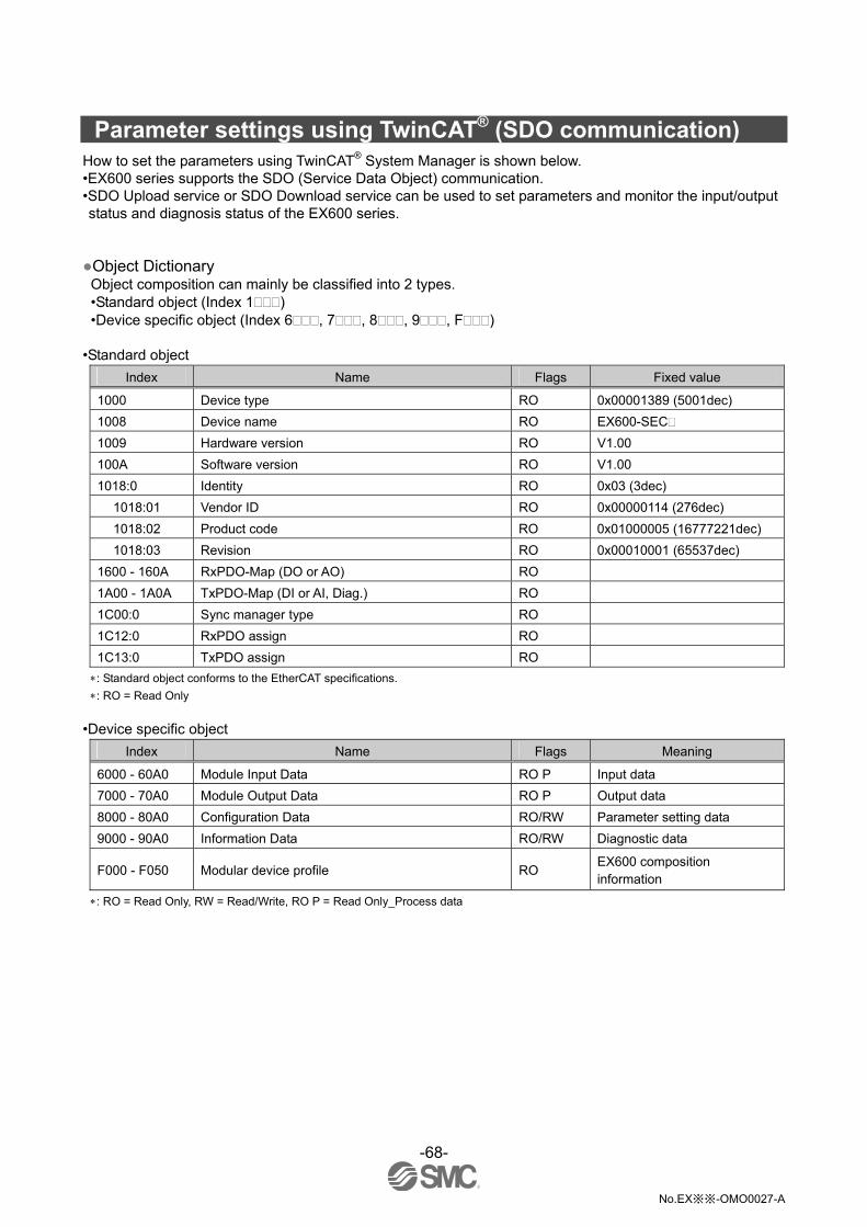
-68-
No.EX※※-OMO0027-A
Parameter settings using TwinCAT® (SDO communication) How to set the parameters using TwinCAT® System Manager is shown below. •EX600 series supports the SDO (Service Data Object) communication. •SDO Upload service or SDO Download service can be used to set parameters and monitor the input/output status and diagnosis status of the EX600 series.
Object Dictionary Object composition can mainly be classified into 2 types. •Standard object (Index 1 ) •Device specific object (Index 6 , 7 , 8 , 9 , F )
•Standard object
Index Name Flags Fixed value
1000 Device type RO 0x00001389 (5001dec)
1008 Device name RO EX600-SEC
1009 Hardware version RO V1.00
100A Software version RO V1.00
1018:0 Identity RO 0x03 (3dec)
1018:01 Vendor ID RO 0x00000114 (276dec)
1018:02 Product code RO 0x01000005 (16777221dec)
1018:03 Revision RO 0x00010001 (65537dec)
1600 - 160A RxPDO-Map (DO or AO) RO
1A00 - 1A0A TxPDO-Map (DI or AI, Diag.) RO
1C00:0 Sync manager type RO
1C12:0 RxPDO assign RO
1C13:0 TxPDO assign RO
: Standard object conforms to the EtherCAT specifications.
: RO = Read Only
•Device specific object
Index Name Flags Meaning
6000 - 60A0 Module Input Data RO P Input data
7000 - 70A0 Module Output Data RO P Output data
8000 - 80A0 Configuration Data RO/RW Parameter setting data
9000 - 90A0 Information Data RO/RW Diagnostic data
F000 - F050 Modular device profile RO EX600 composition information
: RO = Read Only, RW = Read/Write, RO P = Read Only_Process data
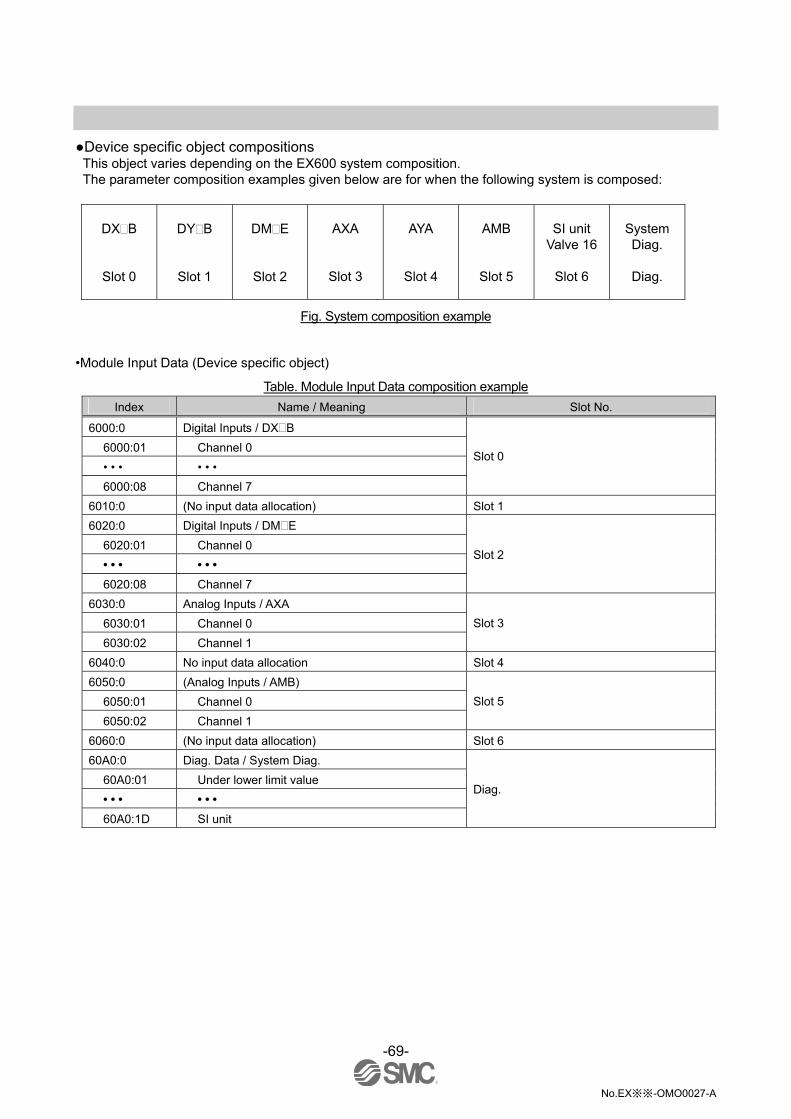
-69-
No.EX※※-OMO0027-A
Device specific object compositions This object varies depending on the EX600 system composition. The parameter composition examples given below are for when the following system is composed:
DX B
Slot 0
DY B
Slot 1
DM E
Slot 2
AXA
Slot 3
AYA
Slot 4
AMB
Slot 5
SI unit Valve 16
Slot 6
System Diag.
Diag.
Fig. System composition example •Module Input Data (Device specific object)
Table. Module Input Data composition example
Index Name / Meaning Slot No.
6000:0 Digital Inputs / DX B
6000:01 Channel 0
• • • • • •
6000:08 Channel 7
Slot 0
6010:0 (No input data allocation) Slot 1
6020:0 Digital Inputs / DM E
6020:01 Channel 0
• • • • • •
6020:08 Channel 7
Slot 2
6030:0 Analog Inputs / AXA
6030:01 Channel 0
6030:02 Channel 1
Slot 3
6040:0 No input data allocation Slot 4
6050:0 (Analog Inputs / AMB)
6050:01 Channel 0
6050:02 Channel 1
Slot 5
6060:0 (No input data allocation) Slot 6
60A0:0 Diag. Data / System Diag.
60A0:01 Under lower limit value
• • • • • •
60A0:1D SI unit
Diag.

-70-
No.EX※※-OMO0027-A
•Module Output Data (Device specific object)
Table. Module Output Data composition example
Index Name / Meaning Slot No.
7000:0 (No output data allocation) Slot 0
7010:0 Digital Outputs / DY(B
7010:01 Channel 0
• • • • • •
7010:08 Channel 7
Slot 1
7020:0 Digital Outputs / DM(E
7020:01 Channel 0
• • • • • •
7020:08 Channel 7
Slot 2
7030:0 (No output data allocation) Slot 3
7040:0 Analog Outputs / AYA
7040:01 Channel 0
7040:02 Channel 1
Slot 4
7050:0 Analog Outputs / AMB
7050:01 Channel 2
7050:02 Channel 3
Slot 5
7060:0 Valve Outputs / SI unit
7060:01 Channel 0
• • • • • •
7060:10 Channel 15
Slot 6
70A0:0 (No output data allocation) Diag.
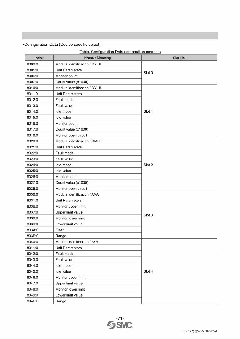
-71-
No.EX※※-OMO0027-A
•Configuration Data (Device specific object)
Table. Configuration Data composition example
Index Name / Meaning Slot No.
8000:0 Module identification / DX B
8001:0 Unit Parameters
8006:0 Monitor count
8007:0 Count value (x1000)
Slot 0
8010:0 Module identification / DY B
8011:0 Unit Parameters
8012:0 Fault mode
8013:0 Fault value
8014:0 Idle mode
8015:0 Idle value
8016:0 Monitor count
8017:0 Count value (x1000)
8018:0 Monitor open circuit
Slot 1
8020:0 Module identification / DM E
8021:0 Unit Parameters
8022:0 Fault mode
8023:0 Fault value
8024:0 Idle mode
8025:0 Idle value
8026:0 Monitor count
8027:0 Count value (x1000)
8028:0 Monitor open circuit
Slot 2
8030:0 Module identification / AXA
8031:0 Unit Parameters
8036:0 Monitor upper limit
8037:0 Upper limit value
8038:0 Monitor lower limit
8039:0 Lower limit value
803A:0 Filter
803B:0 Range
Slot 3
8040:0 Module identification / AYA
8041:0 Unit Parameters
8042:0 Fault mode
8043:0 Fault value
8044:0 Idle mode
8045:0 Idle value
8046:0 Monitor upper limit
8047:0 Upper limit value
8048:0 Monitor lower limit
8049:0 Lower limit value
804B:0 Range
Slot 4
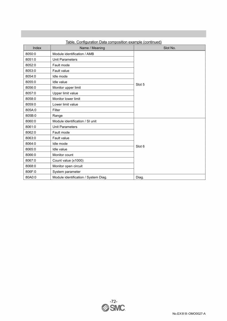
-72-
No.EX※※-OMO0027-A
Table. Configuration Data composition example (continued)
Index Name / Meaning Slot No.
8050:0 Module identification / AMB
8051:0 Unit Parameters
8052:0 Fault mode
8053:0 Fault value
8054:0 Idle mode
8055:0 Idle value
8056:0 Monitor upper limit
8057:0 Upper limit value
8058:0 Monitor lower limit
8059:0 Lower limit value
805A:0 Filter
805B:0 Range
Slot 5
8060:0 Module identification / SI unit
8061:0 Unit Parameters
8062:0 Fault mode
8063:0 Fault value
8064:0 Idle mode
8065:0 Idle value
8066:0 Monitor count
8067:0 Count value (x1000)
8068:0 Monitor open circuit
806F:0 System parameter
Slot 6
80A0:0 Module identification / System Diag. Diag.

-73-
No.EX※※-OMO0027-A
•Information Data (Device specific object)
Table. Information Data composition example
Index Name / Meaning Slot No.
9000:0 Module identification / DX B
9001:0 Short circuit
9002:0 Over ON/OFF counter
9004:0 Counter
Slot 0
9010:0 Module identification / DY(B
9011:0 Short circuit
9012:0 Over ON/OFF counter
9013:0 Open circuit
9014:0 Counter
Slot 1
9020:0 Module identification / DM(E
9021:0 Short circuit
9022:0 Over ON/OFF counter
9023:0 Open circuit
9024:0 Counter
Slot 2
9030:0 Module identification / AXA
9031:0 Short circuit
9032:0 Over range
9033:0 Under range
9034:0 Over upper limit value
9035:0 Under lower limit value
Slot 3
9040:0 Module identification / AYA
9041:0 Short circuit
9044:0 Over upper limit value
9045:0 Under lower limit value
Slot 4
9050:0 Module identification / AMB
9051:0 Short circuit
9052:0 Over range
9053:0 Under range
9054:0 Over upper limit value
9055:0 Under lower limit value
Slot 5
9060:0 Module identification / SI unit
9061:0 Short circuit
9062:0 Over ON/OFF counter
9063:0 Open circuit
9064:0 Counter
9066:0 System error
9067:0 Error log
Slot 6
90A0:0 Module identification / System Diag. Diag.

-74-
No.EX※※-OMO0027-A
Object Dictionary for user set-up •Enumeration definition
Table. User setup Object Dictionary
Index Base Type Value Text
0 0.1 ms
1 1 ms
2 10 ms 0800 USINT
3 20 ms
0 1 ms
1 15 ms
2 100 ms 0801 USINT
3 200 ms
0 Offset binary
1 Sign & magnitude
2 2's complement 0802 USINT
3 Scaled
0 None
1 2 value average
2 4 value average 0803 USINT
3 8 value average
0 -10…+10 V
1 -5…+5 V
2 -20…+20 mA
3 0…10 V
4 0…5 V
5 1…5 V
6 0…20 mA
0804 USINT
7 4…20 mA
0 0…10 V
1 0…5 V
2 1…5 V
3 0…20 mA
0805 USINT
4 4…20 mA
0 Switch 0806 USINT
1 Parameter
0 Disable 0807 USINT
1 Enable
0 Manual 0808 USINT
1 Auto
0 Off 0809 USINT
1 On
0 Offset binary
1 Sign & magnitude 080A USINT
2 2's complement

-75-
No.EX※※-OMO0027-A
Device specific object parameter details •Module Input Data Digital input unit (EX600-DX or EX600-DM )
Table. Module Input Data (DX or DM)
Index Name / Meaning Type Flags Value
60x0:0 Slot x: Digital Inputs USINT RO Number of channels
60x0:01 Channel 0 BOOL RO P FALSE (OFF) TRUE (ON)
• • • • • • • • • • • • • • •
: x = Slot No.
Analogue input unit (EX600-AXA or EX600-AMB)
Table. Module Input Data (AX or AM)
Index Name / Meaning Type Flags Value
60x0:0 Slot x: Analog Inputs USINT RO Number of channels
60x0:01 Channel 0 UINT RO P 0 to 65535
60x0:02 Channel 1 UINT RO P 0 to 65535
: x = Slot No.

-76-
No.EX※※-OMO0027-A
•Diagnostic data
Table. Module Input Data (Diag.)
Index Name / Meaning Type Flags Value
60A0:0 Diag. data USINT RO 29 or 42
60A0:01 Under lower limit value BOOL RO P
60A0:02 Over upper limit value BOOL RO P
60A0:03 Under range BOOL RO P
60A0:04 Over range BOOL RO P
60A0:05 Over ON/OFF counter BOOL RO P
60A0:06 Open circuit BOOL RO P
60A0:07 Short circuit (out) BOOL RO P
60A0:08 Short circuit (in) BOOL RO P
60A0:09 Pwr output is out of range BOOL RO P
60A0:0A Pwr control is out of range BOOL RO P
60A0:0C Unit disconnection BOOL RO P
60A0:0D Connection error BOOL RO P
60A0:0F Memory error BOOL RO P
60A0:10 Parameter read/write error BOOL RO P
60A0:19 Digital input unit BOOL RO P
60A0:1A Digital output unit BOOL RO P
60A0:1B Analog input unit BOOL RO P
60A0:1C Analog output unit BOOL RO P
60A0:1D SI unit BOOL RO P
60A0:21 Slot 0 BOOL RO P
60A0:22 Slot 1 BOOL RO P
60A0:23 Slot 2 BOOL RO P
60A0:24 Slot 3 BOOL RO P
60A0:25 Slot 4 BOOL RO P
60A0:26 Slot 5 BOOL RO P
60A0:27 Slot 6 BOOL RO P
60A0:28 Slot 7 BOOL RO P
60A0:29 Slot 8 BOOL RO P
60A0:2A Slot 9 BOOL RO P
FALSE (Undetected) TRUE (Detected)

-77-
No.EX※※-OMO0027-A
•Module Output Data SI unit (EX600-SEC )
Table. Module Output Data (SI)
Index Name / Meaning Type Flags Value
70x0:0 Slot x: Valve Outputs USINT RO Number of channels
70x0:01 Channel 0 BOOL RO P FALSE (OFF) TRUE (ON)
• • • • • • • • • • • • • • •
: x: Slot No.
Digital output unit (EX600-DY or EX600-DM )
Table. Module Output Data (DY or DM)
Index Name / Meaning Type Flags Value
70x0:0 Slot x: Digital Outputs USINT RO Number of channels
70x0:01 Channel 0 BOOL RO P FALSE (OFF) TRUE (ON)
• • • • • • • • • • • • • • •
: x: Slot No.
Analogue output unit (EX600-AYA or EX600-AMB)
Table. Module Output Data (AY or AM)
Index Name / Meaning Type Flags Value
70x0:0 Slot x: Analog Outputs USINT RO Number of channels
70x0:01 Channel 0 UINT RO P 0 to 65535
70x0:02 Channel 1 UINT RO P 0 to 65535
: x: Slot No.

-78-
No.EX※※-OMO0027-A
•Configuration Data SI unit (EX600-SEC )
Table. Configuration Data (SI)
Index Name / Meaning Type Value
80x0:0 Slot x: Module identification USINT 10
80x0:01 Address of the module UINT Slot No.
80x0:09 Module PDO group UINT 2
80x0:0A Module ident DINT Unit ID
80x1:0 Slot x: Unit Parameters USINT 8
80x1:02 Monitor short circuit (out) Enum08070=Disable 1=Enable
80x1:06 Restart after short circuit Enum08080=Manual 1=Auto
80x1:07 Monitor 24V_C / Monitoring the power supply voltage (For control and input)
Enum08070=Disable 1=Enable
80x1:08 Monitor 24V_D / Monitoring the power supply voltage (For output)
Enum08070=Disable 1=Enable
80x2:0 Slot x: Fault mode USINT Number of channels
80x2:01 Channel 0 / Output setting during communication fault
Enum08070=Disable (Hold) 1=Enable (Clear or Force ON)
• • • • • • • • • • • •
80x3:0 Slot x: Fault value USINT Number of channels
80x3:01 Channel 0 / Output setting value during communication fault
Enum08090=Off (Clear) 1=On (Force ON)
• • • • • • • • • • • •
80x4:0 Slot x: Idle mode USINT Number of channels
80x4:01 Channel 0 / Output setting during communication idling
Enum08070=Disable (Hold) 1=Enable (Clear or Force ON)
• • • • • • • • • • • •
80x5:0 Slot x: Idle value USINT Number of channels
80x5:01 Channel 0 / Output setting value during communication idling
Enum08090=Off (Clear) 1=On (Force ON)
• • • • • • • • • • • •
80x6:0 Slot x: Monitor count USINT Number of channels
80x6:01 Channel 0 / ON-OFF counter upper limit Enum08070=Disable 1=Enable
• • • • • • • • • • • •
80x7:0 Slot x: Count value (x1000) USINT Number of channels
80x7:01 Channel 0 / ON-OFF frequency upper limit UINT 1 to 65000 (Times diagnostic has been detected=Set value x1000)
• • • • • • • • • • • •

-79-
No.EX※※-OMO0027-A
Table. Configuration Data (SI) (continued)
Index Name / Meaning Type Value
80x8:0 Slot x: Monitor open circuit USINT Number of channels
80x8:01 Channel 0 / Open circuit detection Enum08070=Disable 1=Enable
• • • • • • • • • • • •
80xF:0 Slot x: System parameter USINT 2
80xF:02 Hold/Clear Enum08060=Switch 1=H.T. or parameter
: x: Slot No.
Digital input unit (EX600-DX )
Table. Configuration Data (DX)
Index Name / Meaning Type Value
80x0:0 Slot x: Module identification USINT 10
80x0:01 Address of the module UINT Slot No.
80x0:09 Module PDO group UINT 2
80x0:0A Module ident DINT Unit ID
80x1:0 Slot x: Unit Parameters USINT 11
80x1:01 Monitor short circuit (in) Enum08070=Disable 1=Enable
80x1:05 Inrush current filter Enum08070=Disable 1=Enable
80x1:09 Digital input filtering time Enum0800
0=0.1 ms 1=1 ms 2=10 ms 3=20 ms
80x1:0B Digital input extension time Enum0801
0=1 ms 1=15 ms 2=100 ms 3=200 ms
80x6:0 Slot x: Monitor count USINT Number of channels
80x6:01 Channel 0 / ON-OFF counter upper limit Enum08070=Disable 1=Enable
• • • • • • • • • • • •
80x7:0 Slot x: Count Value (x1000) USINT Number of channels
80x7:01 Channel 0 / ON-OFF frequency upper limit UINT 1 to 65000 (Times diagnostic has been detected=Set value x1000)
• • • • • • • • • • • •
80x8:0 1 Slot x: Monitor open circuit USINT Number of channels
80x8:01 1 Channel 0 / Open circuit detection Enum08070=Disable 1=Enable
• • • 1 • • • • • • • • •
: x: Slot No.
1: Applicable to the open detecting digital input unit (EX600-DXC1).

-80-
No.EX※※-OMO0027-A
Digital output unit (EX600-DY )
Table. Configuration Data (DY)
Index Name / Meaning Type Value
80x0:0 Slot x: Module identification USINT 10
80x0:01 Address of the module UINT Slot No.
80x0:09 Module PDO group UINT 2
80x0:0A Module ident DINT Unit ID
80x1:0 Slot x: Unit Parameters USINT 6
80x1:02 Monitor short circuit (out) Enum08070=Disable 1=Enable
80x1:06 Restart after short circuit Enum08080=Manual 1=Auto
80x2:0 Slot x: Fault mode USINT Number of channels
80x2:01 Channel 0 / Output setting during communication fault
Enum08070=Disable (Hold) 1=Enable (Clear or Force ON)
• • • • • • • • • • • •
80x3:0 Slot x: Fault value USINT Number of channels
80x3:01 Channel 0 / Output setting value during communication fault
Enum08090=Off (Clear) 1=On (Force ON)
• • • • • • • • • • • •
80x4:0 Slot x: Idle mode USINT Number of channels
80x4:01 Channel 0 / Output setting during communication idling
Enum08070=Disable (Hold) 1=Enable (Clear or Force ON)
• • • • • • • • • • • •
80x5:0 Slot x: Idle value USINT Number of channels
80x5:01 Channel 0 / Output setting value during communication idling
Enum08090=Off (Clear) 1=On (Force ON)
• • • • • • • • • • • •
80x6:0 Slot x: Monitor count USINT Number of channels
80x6:01 Channel 0 / ON-OFF counter upper limit Enum08070=Disable 1=Enable
• • • • • • • • • • • •
80x7:0 Slot x: Count value (x1000) USINT Number of channels
80x7:01 Channel 0 / ON-OFF frequency upper limit UINT 1 to 65000 (Times diagnostic has been detected=Set value x1000)
• • • • • • • • • • • •
80x8:0 Slot x: Monitor open circuit USINT Number of channels
80x8:01 Channel 0 / Open circuit detection Enum08070=Disable 1=Enable
• • • • • • • • • • • •
: x: Slot No.

-81-
No.EX※※-OMO0027-A
Digital I/O unit (EX600-DM )
Table. Configuration Data (DM)
Index Name / Meaning Type Value
80x0:0 Slot x: Module identification USINT 10
80x0:01 Address of the module UINT Slot No.
80x0:09 Module PDO group UINT 2
80x0:0A Module ident DINT Unit ID
80x1:0 Slot x: Unit Parameters USINT 11
80x1:01 Monitor short circuit (in) Enum08070=Disable 1=Enable
80x1:02 Monitor short circuit (out) Enum08070=Disable 1=Enable
80x1:05 Inrush current filter Enum08070=Disable 1=Enable
80x1:06 Restart after short circuit Enum08080=Manual 1=Auto
80x1:09 Digital input filtering time Enum0800
0=0.1 ms 1=1 ms 2=10 ms 3=20 ms
80x1:0B Digital input extension time Enum0801
0=1 ms 1=15 ms 2=100 ms 3=200 ms
80x2:0 Slot x: Fault mode USINT Number of output channels
80x2:01 Channel 0 (Out) / Output setting during communication fault
Enum08070=Disable (Hold) 1=Enable (Clear or Force ON)
• • • • • • • • • • • •
80x3:0 Slot x: Fault value USINT Number of output channels
80x3:01 Channel 0 (Out) / Output setting value during communication fault
Enum08090=Off (Clear) 1=On (Force ON)
• • • • • • • • • • • •
80x4:0 Slot x: Idle mode USINT Number of output channels
80x4:01 Channel 0 (Out) / Output setting during communication idling
Enum08070=Disable (Hold) 1=Enable (Clear or Force ON)
• • • • • • • • • • • •
80x5:0 Slot x: Idle value USINT Number of output channels
80x5:01 Channel 0 (Out) / Output setting value during communication idling
Enum08090=Off (Clear) 1=On (Force ON)
• • • • • • • • • • • •
80x6:0 Slot x: Monitor count USINT Number of all channels
80x6:01 Channel 0 (In) / ON-OFF count upper limit detection
Enum08070=Disable 1=Enable
• • • • • • • • • • • •
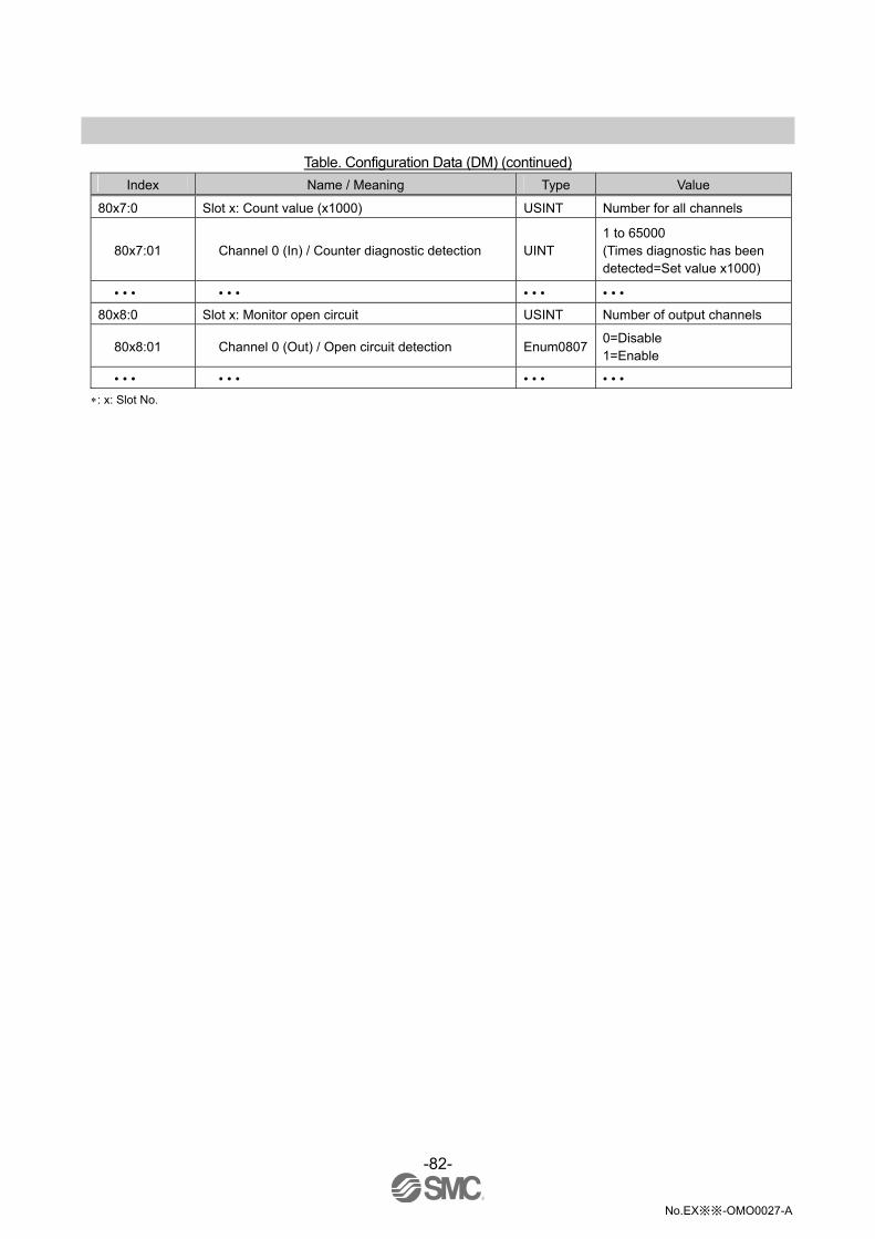
-82-
No.EX※※-OMO0027-A
Table. Configuration Data (DM) (continued)
Index Name / Meaning Type Value
80x7:0 Slot x: Count value (x1000) USINT Number for all channels
80x7:01 Channel 0 (In) / Counter diagnostic detection UINT 1 to 65000 (Times diagnostic has been detected=Set value x1000)
• • • • • • • • • • • •
80x8:0 Slot x: Monitor open circuit USINT Number of output channels
80x8:01 Channel 0 (Out) / Open circuit detection Enum08070=Disable 1=Enable
• • • • • • • • • • • •
: x: Slot No.

-83-
No.EX※※-OMO0027-A
Analogue input unit (EX600-AXA)
Table. Configuration Data (AX)
Index Name / Meaning Type Value
80x0:0 Slot x: Module identification USINT 10
80x0:01 Address of the module UINT Slot No.
80x0:09 Module PDO group UINT 1
80x0:0A Module ident DINT 32
80x1:0 Slot x: Unit Parameters USINT 13
80x1:01 Monitor short circuit (in) Enum08070=Disable 1=Enable
80x1:03 Monitor over range Enum08070=Disable 1=Enable
80x1:04 Monitor under range Enum08070=Disable 1=Enable
80x1:0D Data format Enum080A
0=Offset binary 1=Sign & Magnitude 2=2's complement
80x6:0 Slot x: Monitor upper limit USINT 2
80x6:01 Channel 0 / Monitor user set upper limit
80x6:02 Channel 1 / Monitor user set upper limit Enum0807
0=Disable 1=Enable
80x7:0 Slot x: Upper limit value USINT 2
80x7:01 Channel 0 / User set upper limit value
80x7:02 Channel 1 / User set upper limit value UINT 0 to 65535
80x8:0 Slot x: Monitor lower limit USINT 2
80x8:01 Channel 0 / Monitor user set lower limit
80x8:02 Channel 1 / Monitor user set lower limit Enum0807
0=Disable 1=Enable
80x9:0 Slot x: Lower limit value USINT 2
80x9:01 Channel 0 / User set lower limit value
80x9:02 Channel 1 / User set lower limit value UINT 0 to 65535
80xA:0 Slot x: Filter USINT 2
80xA:01 Channel 0 / Analogue average filter
80xA:02 Channel 1 / Analogue average filter
Enum0803
0=None 1=2 value average 2=4 value average 3=8 value average
80xB:0 Slot x: Range USINT 2
80xB:01 Channel 0 / Analogue input range
80xB:02 Channel 1 / Analogue input range
Enum0804
0=-10…+10 V 1=-5…+5 V 2=-20…+20 mA 3=0…10 V 4=0…5 V 5=1…5 V 6=0…20 mA 7=4…20 mA
: x: Slot No.

-84-
No.EX※※-OMO0027-A
Analogue output unit (EX600-AYA)
Table. Configuration Data (AY)
Index Name / Meaning Type Value
80x0:0 Slot x: Module identification USINT 10
80x0:01 Address of the module UINT Slot No.
80x0:09 Module PDO group UINT 1
80x0:0A Module ident DINT 34
80x1:0 Slot x: Unit Parameters USINT 13
80x1:01 Monitor short circuit (in) Enum08070=Disable 1=Enable
80x1:0D Data format Enum0802
0=Offset binary 1=Sign & Magnitude 2=2's complement 3=Scaled
80x2:0 Slot x: Fault mode USINT 2
80x2:01 Channel 0 / Output setting during communication fault
80x2:02 Channel 1 / Output setting during communication fault
Enum08070=Disable (Hold) 1=Enable (Fault value)
80x3:0 Slot x: Fault value USINT 2
80x3:01 Channel 0 / Output setting value during communication fault
80x3:02 Channel 1 / Output setting value during communication fault
UINT 0 to 65535
80x4:0 Slot x: Idle mode USINT 2
80x4:01 Channel 0 / Output setting during communication idling
80x4:02 Channel 1 / Output setting during communication idling
Enum08070=Disable (Hold) 1=Enable (Fault value)
80x5:0 Slot x: Idle value USINT 2
80x5:01 Channel 0 / Output setting value during communication idling
80x5:02 Channel 1 / Output setting value during communication idling
UINT 0 to 65535
80x6:0 Slot x: Monitor upper limit USINT 2
80x6:01 Channel 0 / Monitor user set upper limit
80x6:02 Channel 1 / Monitor user set upper limit Enum0807
0=Disable 1=Enable
80x7:0 Slot x: Upper limit value USINT 2
80x7:01 Channel 0 / User set upper limit value
80x7:02 Channel 1 / User set upper limit value UINT 0 to 65535

-85-
No.EX※※-OMO0027-A
Table. Configuration Data (AY) (continued)
Index Name / Meaning Type Value
80x8:0 Slot x: Monitor lower limit USINT 2
80x8:01 Channel 0 / Monitor user set lower limit
80x8:02 Channel 1 / Monitor user set lower limit Enum0807
0=Disable 1=Enable
80x9:0 Slot x: Lower limit value USINT 2
80x9:01 Channel 0 / User set lower limit value
80x9:02 Channel 1 / User set lower limit value UINT 0 to 65535
80xB:0 Slot x: Range USINT 2
80xB:01 Channel 0 / Analogue output range
80xB:02 Channel 1 / Analogue output range
Enum0805
0=0…10 V 1=0…5 V 2=1…5 V 3=0…20 mA 4=4…20 mA
: x: Slot No.

-86-
No.EX※※-OMO0027-A
Analogue I/O unit (EX600-AMB)
Table. Configuration Data (AM)
Index Name / Meaning Type Value
80x0:0 Slot x: Module identification USINT 10
80x0:01 Address of the module UINT Slot No.
80x0:09 Module PDO group UINT 1
80x0:0A Module ident DINT 35
80x1:0 Slot x: Unit Parameters USINT 13
80x1:01 Monitor short circuit (in) Enum08070=Disable 1=Enable
80x1:03 Monitor over range Enum08070=Disable 1=Enable
80x1:04 Monitor under range Enum08070=Disable 1=Enable
80x1:0D Data format Enum0802
0=Offset binary 1=Sign & Magnitude 2=2's complement 3=Scaled
80x2:0 Slot x: Fault mode USINT 2
80x2:01 Channel 2 / Output setting during communication fault
80x2:02 Channel 3 / Output setting during communication fault
Enum08070=Disable (Hold) 1=Enable (Fault value)
80x3:0 Slot x: Fault value USINT 2
80x3:01 Channel 2 / Output setting value during communication fault
80x3:02 Channel 3 / Output setting value during communication fault
UINT 0 to 65535
80x4:0 Slot x: Idle mode USINT 2
80x4:01 Channel 2 / Output setting during communication idling
80x4:02 Channel 3 / Output setting during communication idling
Enum08070=Disable (Hold) 1=Enable (Fault value)
80x5:0 Slot x: Idle value USINT 2
80x5:01 Channel 2 / Output setting value during communication idling
80x5:02 Channel 3 / Output setting value during communication idling
UINT 0 to 65535
80x6:0 Slot x: Monitor upper limit USINT 4
80x6:01 Channel 0 / Monitor user set upper limit Enum08070=Disable 1=Enable
• • • • • • • • • • • •

-87-
No.EX※※-OMO0027-A
Table. Configuration Data (AM) (continued)
Index Name / Meaning Type Value
80x7:0 Slot x: Upper limit value USINT 4
80x7:01 Channel 0 / User set upper limit value UINT 0 to 65535
• • • • • • • • • • • •
80x8:0 Slot x: Monitor lower limit USINT 4
80x8:01 Channel 0 / Monitor user set lower limit Enum08070=Disable 1=Enable
• • • • • • • • • • • •
80x9:0 Slot x: Lower limit value USINT 4
80x9:01 Channel 0 / User set lower limit value UINT 0 to 65535
• • • • • • • • • • • •
80xA:0 Slot x: Filter USINT 2
80xA:01 Channel 0 / Analogue average filter
80xA:02 Channel 1 / Analogue average filter
Enum0803
0=None 1=2 value average 2=4 value average 3=8 value average
80xB:0 Slot x: Range USINT 4
80xB:01 Channel 0 / Analogue range Enum0805
0=0…10 V 1=0…5 V 2=1…5 V 3=0…20 mA 4=4…20 mA
• • • • • • • • • • • •
: x: Slot No.
: Channel 0 and 1 indicate analogue input, and Channel 2 and 3 indicate analogue output.

-88-
No.EX※※-OMO0027-A
•Diagnostic data
Table. Configuration Data (Diag.)
Index Name / Meaning Type Value
80A0:0 Diag.: Module identification USINT 10
80A0:01 Address of the module UINT 10
80A0:09 Module PDO group UINT 0
80A0:0A Module ident DINT 256 or 257

-89-
No.EX※※-OMO0027-A
•Information Data SI unit (EX600-SEC )
Table. Information Data (SI)
Index Name / Meaning Type Value
90x0:0 Slot x: Module identification USINT 10
90x0:01 Address of the module UINT Slot No.
90x0:09 Module PDO group UINT 2
90x0:0A Module ident DINT Unit ID
90x1:0 Slot x: Short circuit USINT Number of channels
90x1:01 Channel 0 BOOL FALSE (Undetected) TRUE (Detected)
• • • • • • • • • • • •
90x2:0 Slot x: Over ON/OFF counter USINT Number of channels
90x2:01 Channel 0 BOOL FALSE (Undetected) TRUE (Detected)
• • • • • • • • • • • •
90x3:0 Slot x: Open circuit USINT Number of channels
90x3:01 Channel 0 BOOL FALSE (Undetected) TRUE (Detected)
• • • • • • • • • • • •
90x4:0 Slot x: Counter USINT Number of channels
90x4:01 Channel 0 UDINT 0 to 4294967295
• • • • • • • • • • • •
90x6:0 Slot x: System error USINT 8
90x6:01 Pwr output is out of range BOOL FALSE (Undetected) TRUE (Detected)
90x6:02 Pwr control is out of range BOOL FALSE (Undetected) TRUE (Detected)
90x6:04 Unit disconnection BOOL FALSE (Undetected) TRUE (Detected)
90x6:05 Connection error BOOL FALSE (Undetected) TRUE (Detected)
90x6:06 Unit registration error BOOL FALSE (Undetected) TRUE (Detected)
90x6:07 Memory error BOOL FALSE (Undetected) TRUE (Detected)
90x6:08 Parameter read/write error BOOL FALSE (Undetected) TRUE (Detected)
90x7:0 Slot x: Error log USINT 30
90x7:01 Log 0 STRING 1
• • • • • • • • • • • •
: x: Slot No.
1: Error log indication example is shown below.

-90-
No.EX※※-OMO0027-A
•When the slot and channel are not specified, "--" will be displayed. •When there is no log, "No error" will be displayed.
Fig. Log format
Table. Error code list
Error code Content
0 -
1 Short circuit has occurred.
2 Analogue input value has exceeded the lower limit of the range.
3 Analogue input value has exceeded the upper limit of the range.
4 -
5 -
6 Broken wire is detected.
7 Analogue value (value set by user) has exceeded the upper limit.
8 Analogue value (value set by user) has exceeded the lower limit.
9 ON/OFF count has exceeded the set value.
10 to 15 -
16 Power supply voltage level for control and inputs is abnormal.
17 Power supply voltage level for output is abnormal.
18 -
19 Connection error between the units. (When operating)
20 Connection error between the units. (When power is supplied)
21 -
22 System error.
23 Internal component has failed.
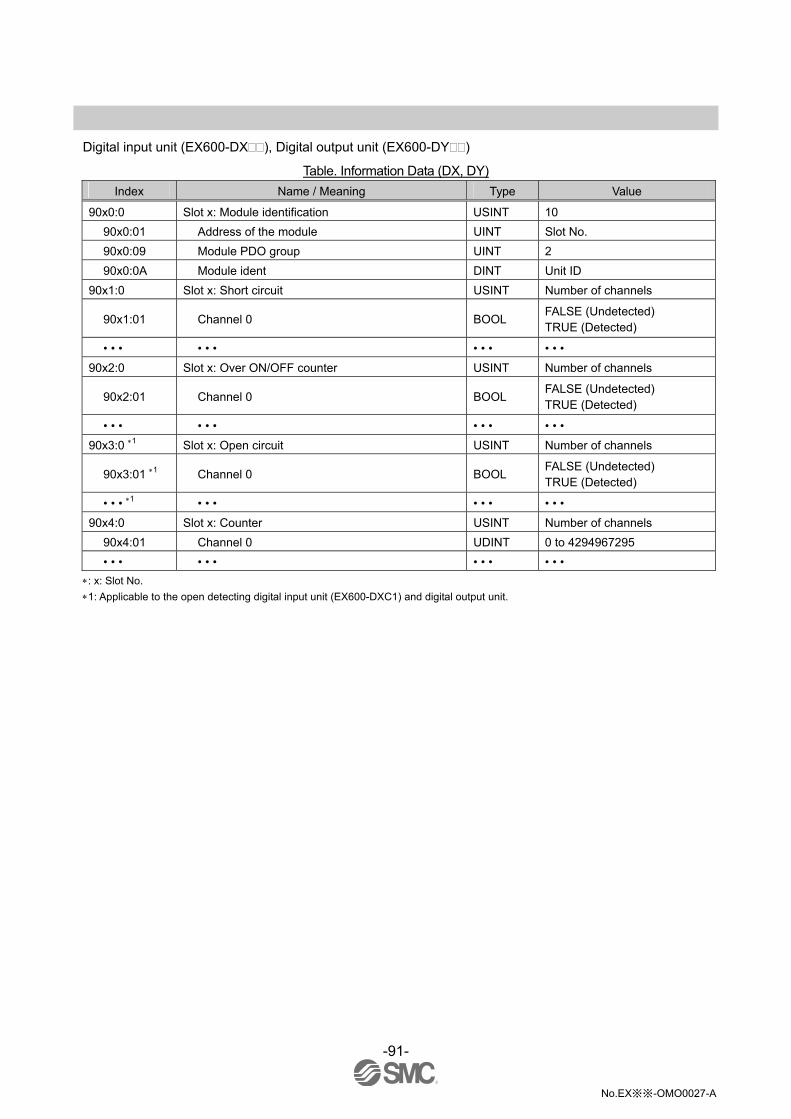
-91-
No.EX※※-OMO0027-A
Digital input unit (EX600-DX ), Digital output unit (EX600-DY )
Table. Information Data (DX, DY)
Index Name / Meaning Type Value
90x0:0 Slot x: Module identification USINT 10
90x0:01 Address of the module UINT Slot No.
90x0:09 Module PDO group UINT 2
90x0:0A Module ident DINT Unit ID
90x1:0 Slot x: Short circuit USINT Number of channels
90x1:01 Channel 0 BOOL FALSE (Undetected) TRUE (Detected)
• • • • • • • • • • • •
90x2:0 Slot x: Over ON/OFF counter USINT Number of channels
90x2:01 Channel 0 BOOL FALSE (Undetected) TRUE (Detected)
• • • • • • • • • • • •
90x3:0 1 Slot x: Open circuit USINT Number of channels
90x3:01 1 Channel 0 BOOL FALSE (Undetected) TRUE (Detected)
• • • 1 • • • • • • • • •
90x4:0 Slot x: Counter USINT Number of channels
90x4:01 Channel 0 UDINT 0 to 4294967295
• • • • • • • • • • • •
: x: Slot No.
1: Applicable to the open detecting digital input unit (EX600-DXC1) and digital output unit.
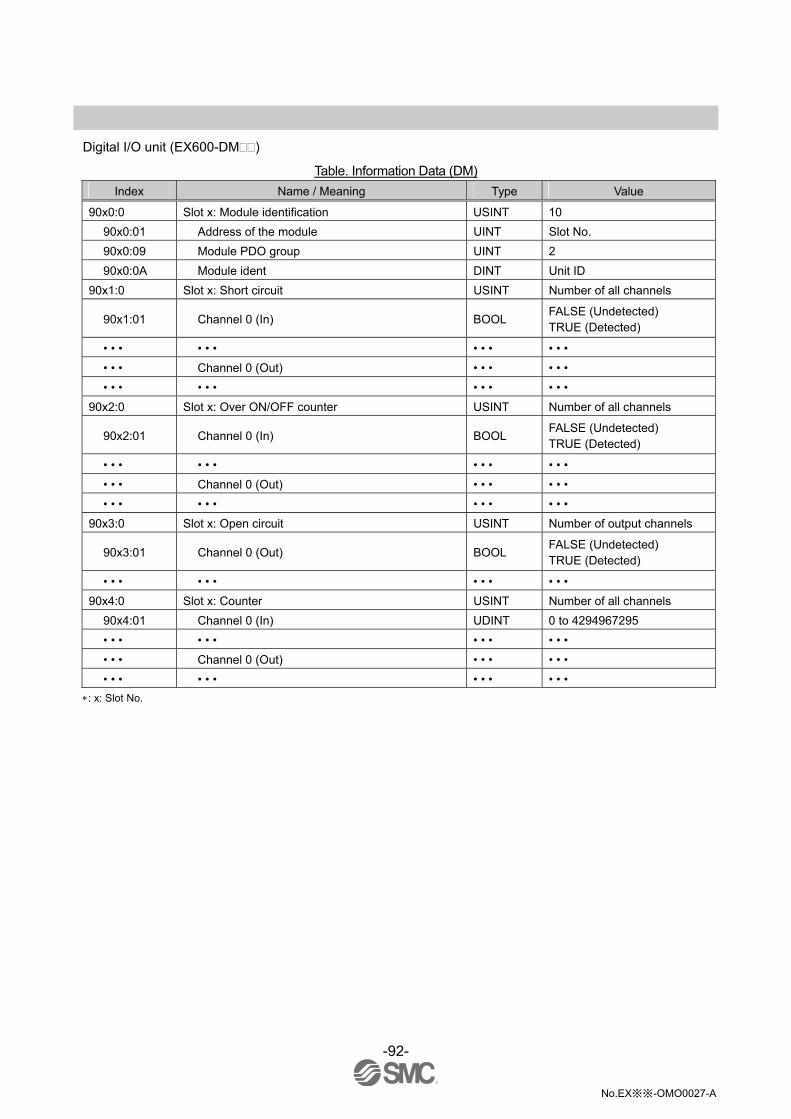
-92-
No.EX※※-OMO0027-A
Digital I/O unit (EX600-DM )
Table. Information Data (DM)
Index Name / Meaning Type Value
90x0:0 Slot x: Module identification USINT 10
90x0:01 Address of the module UINT Slot No.
90x0:09 Module PDO group UINT 2
90x0:0A Module ident DINT Unit ID
90x1:0 Slot x: Short circuit USINT Number of all channels
90x1:01 Channel 0 (In) BOOL FALSE (Undetected) TRUE (Detected)
• • • • • • • • • • • •
• • • Channel 0 (Out) • • • • • •
• • • • • • • • • • • •
90x2:0 Slot x: Over ON/OFF counter USINT Number of all channels
90x2:01 Channel 0 (In) BOOL FALSE (Undetected) TRUE (Detected)
• • • • • • • • • • • •
• • • Channel 0 (Out) • • • • • •
• • • • • • • • • • • •
90x3:0 Slot x: Open circuit USINT Number of output channels
90x3:01 Channel 0 (Out) BOOL FALSE (Undetected) TRUE (Detected)
• • • • • • • • • • • •
90x4:0 Slot x: Counter USINT Number of all channels
90x4:01 Channel 0 (In) UDINT 0 to 4294967295
• • • • • • • • • • • •
• • • Channel 0 (Out) • • • • • •
• • • • • • • • • • • •
: x: Slot No.

-93-
No.EX※※-OMO0027-A
Analogue input unit (EX600-AXA), Analogue output unit (EX600-AYA)
Table. Information Data (AX, AY)
Index Name / Meaning Type Value
90x0:0 Slot x: Module identification USINT 10
90x0:01 Address of the module UINT Slot No.
90x0:09 Module PDO group UINT 1
90x0:0A Module ident DINT 32 (AX) 34 (AY)
90x1:0 Slot x: Short circuit USINT 2
90x1:01 Channel 0 BOOL FALSE (Undetected) TRUE (Detected)
90x1:02 Channel 1 BOOL FALSE (Undetected) TRUE (Detected)
90x2:0 1 Slot x: Over range USINT 2
90x2:01 1 Channel 0 BOOL FALSE (Undetected) TRUE (Detected)
90x2:02 1 Channel 1 BOOL FALSE (Undetected) TRUE (Detected)
90x3:0 1 Slot x: Under range USINT 2
90x3:01 1 Channel 0 BOOL FALSE (Undetected) TRUE (Detected)
90x3:02 1 Channel 1 BOOL FALSE (Undetected) TRUE (Detected)
90x4:0 Slot x: Over upper limit value USINT 2
90x4:01 Channel 0 BOOL FALSE (Undetected) TRUE (Detected)
90x4:02 Channel 1 BOOL FALSE (Undetected) TRUE (Detected)
90x5:0 Slot x: Under lower limit value USINT 2
90x5:01 Channel 0 BOOL FALSE (Undetected) TRUE (Detected)
90x5:02 Channel 1 BOOL FALSE (Undetected) TRUE (Detected)
: x: Slot No.
1: Applicable to the analogue input unit.
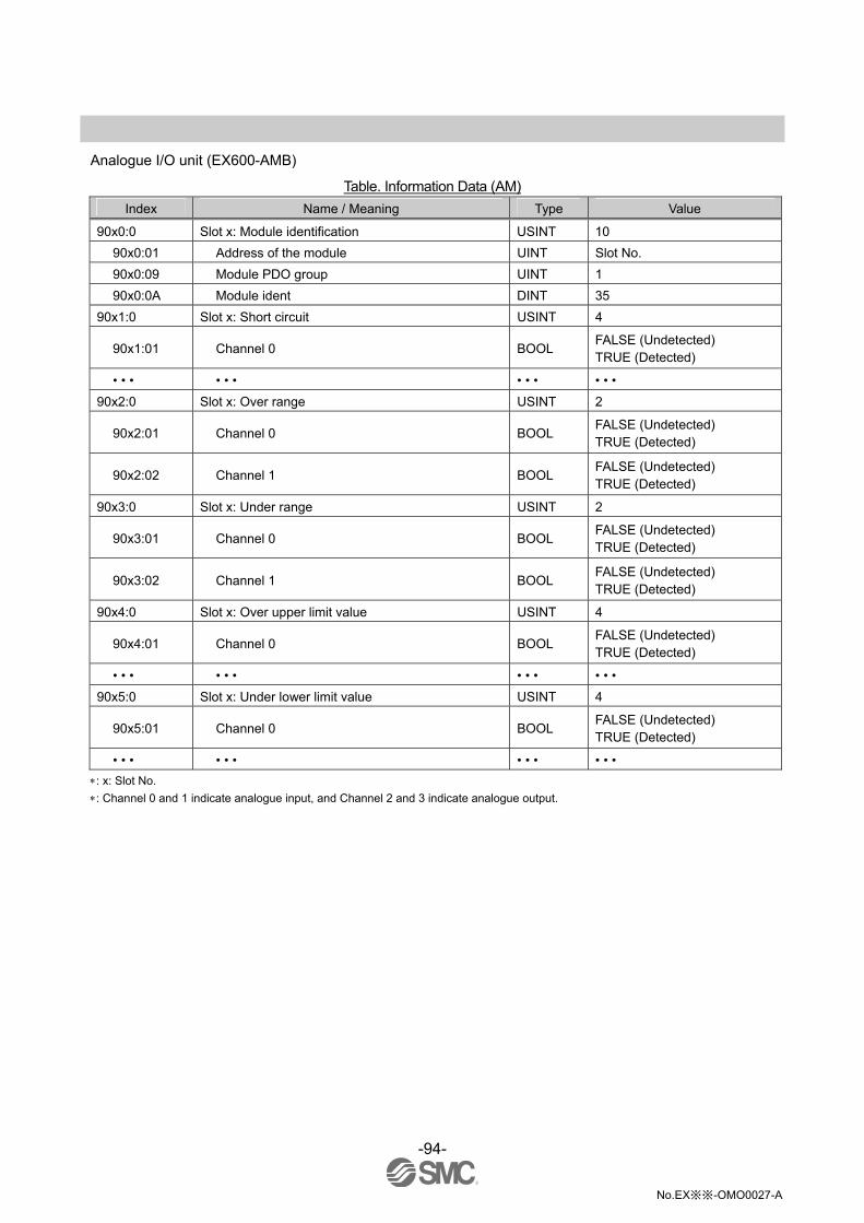
-94-
No.EX※※-OMO0027-A
Analogue I/O unit (EX600-AMB)
Table. Information Data (AM)
Index Name / Meaning Type Value
90x0:0 Slot x: Module identification USINT 10
90x0:01 Address of the module UINT Slot No.
90x0:09 Module PDO group UINT 1
90x0:0A Module ident DINT 35
90x1:0 Slot x: Short circuit USINT 4
90x1:01 Channel 0 BOOL FALSE (Undetected) TRUE (Detected)
• • • • • • • • • • • •
90x2:0 Slot x: Over range USINT 2
90x2:01 Channel 0 BOOL FALSE (Undetected) TRUE (Detected)
90x2:02 Channel 1 BOOL FALSE (Undetected) TRUE (Detected)
90x3:0 Slot x: Under range USINT 2
90x3:01 Channel 0 BOOL FALSE (Undetected) TRUE (Detected)
90x3:02 Channel 1 BOOL FALSE (Undetected) TRUE (Detected)
90x4:0 Slot x: Over upper limit value USINT 4
90x4:01 Channel 0 BOOL FALSE (Undetected) TRUE (Detected)
• • • • • • • • • • • •
90x5:0 Slot x: Under lower limit value USINT 4
90x5:01 Channel 0 BOOL FALSE (Undetected) TRUE (Detected)
• • • • • • • • • • • •
: x: Slot No.
: Channel 0 and 1 indicate analogue input, and Channel 2 and 3 indicate analogue output.

-95-
No.EX※※-OMO0027-A
•Diagnostic data
Table. Information Data (Diag.)
Index Name / Meaning Type Value
90A0:0 Diag.: Module identification USINT 10
90A0:01 Address of the module UINT 10
90A0:09 Module PDO group UINT 0
90A0:0A Module ident DINT 256 or 257
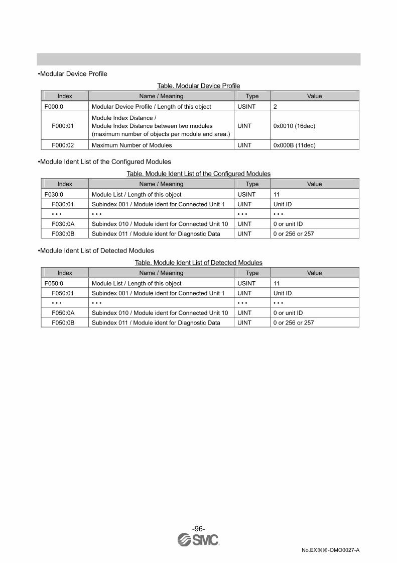
-96-
No.EX※※-OMO0027-A
•Modular Device Profile
Table. Modular Device Profile
Index Name / Meaning Type Value
F000:0 Modular Device Profile / Length of this object USINT 2
F000:01 Module Index Distance / Module Index Distance between two modules (maximum number of objects per module and area.)
UINT 0x0010 (16dec)
F000:02 Maximum Number of Modules UINT 0x000B (11dec)
•Module Ident List of the Configured Modules
Table. Module Ident List of the Configured Modules
Index Name / Meaning Type Value
F030:0 Module List / Length of this object USINT 11
F030:01 Subindex 001 / Module ident for Connected Unit 1 UINT Unit ID
• • • • • • • • • • • •
F030:0A Subindex 010 / Module ident for Connected Unit 10 UINT 0 or unit ID
F030:0B Subindex 011 / Module ident for Diagnostic Data UINT 0 or 256 or 257
•Module Ident List of Detected Modules
Table. Module Ident List of Detected Modules
Index Name / Meaning Type Value
F050:0 Module List / Length of this object USINT 11
F050:01 Subindex 001 / Module ident for Connected Unit 1 UINT Unit ID
• • • • • • • • • • • •
F050:0A Subindex 010 / Module ident for Connected Unit 10 UINT 0 or unit ID
F050:0B Subindex 011 / Module ident for Diagnostic Data UINT 0 or 256 or 257

-97-
No.EX※※-OMO0027-A
Example of how to set parameters •Complete the EX600 configuration. •After selecting [Box1 (EX600-SEC)] in (1), select [CoE-Online] tab (2), then press [Advanced] button.
•Select [All Objects] (4) on the [Advanced Settings] screen, and press [OK] button (5).
(1)
(2)
(3)
(4)
(5)

-98-
No.EX※※-OMO0027-A
•Object Dictionary will be displayed (6).
(6)

-99-
No.EX※※-OMO0027-A
•Index 8011:0 (7) shows the unit parameter of the Digital Inputs Unit of Slot 1. •Value of the Inrush current filter (8) is in the Disable (0) state. •Set Value Dialog (9) will be displayed by double-clicking the Value of Inrush current filter (8). •Parameter can be changed by changing the Enum to Enable (1) and pressing the [OK] button.
(7)
(8)
(9)

-100-
No.EX※※-OMO0027-A
Accessories For the selection of accessories, refer to the catalog.
(1)Valve plate EX600-ZMV1
Enclosed parts: Round head screw (M4 x 6), 2 pcs. Round head screw (M3 x 8), 4 pcs.
EX600-ZMV2 (Specified for SY series) Enclosed parts: Round head screw (M4 x 6), 2 pcs.
Round head screw (M3 x 8), 4 pcs.
(2)End plate bracket EX600-ZMA2
Enclosed parts: Round head screw (M4 x 20), 1 pc. P tight screw (4 x 14), 2 pcs.
EX600-ZMA3 (Specified for SY series) Enclosed parts: Round head screw (M4 x 20) with washer, 1 pc.
P tight screw (4 x 14), 2 pcs.
(3)Intermediate reinforcing brace EX600-ZMB1…for direct mounting
Enclosed parts: Round head screw (M4 x 5), 2 pcs.
EX600-ZMB2…for DIN rail mounting Enclosed parts: Round head screw (M4 x 6), 2 pcs.
(4)Seal cap (10 pcs.) EX9-AWES…for M8 EX9-AWTS…for M12
(5)Marker (1 sheet, 88 pcs.) EX600-ZT1
(6)Y Junction connector
PCA-1557785 2 x M12 (5 pin) – M12 (5 pin) (7)Assembled type connector
PCA-1578078 for power supply, 7/8 inch, Plug, Cable O.D. 12 to 14 mm PCA-1578081 for power supply, 7/8 inch, Socket, Cable O.D. 12 to 14 mm PCA-1446553 for communication EtherCAT, Plug PCA-1557730 M8 (3 pin), Plug PCA-1557743 M12 (4 pin), Plug, for AWG26 to AWG22, SPEEDCON compatible PCA-1557756 M12 (4 pin), Plug, for AWG22 to AWG18, SPEEDCON compatible
(8)Power supply cable
PCA-1558810 Cable with 7/8 inch connector, Socket, Straight 2 m PCA-1558823 Cable with 7/8 inch connector, Socket, Straight 6 m PCA-1558836 Cable with 7/8 inch connector, Socket, Right angle 2 m PCA-1558849 Cable with 7/8 inch connector, Socket, Right angle 6 m PCA-1564927 Cable with M12 connector, B code, Socket, Straight 2 m, SPEEDCON compatible PCA-1564930 Cable with M12 connector, B code, Socket, Straight 6 m, SPEEDCON compatible PCA-1564943 Cable with M12 connector, B code, Socket, Right angle 2 m, SPEEDCON compatible PCA-1564969 Cable with M12 connector, B code, Socket, Right angle 6 m, SPEEDCON compatible
(9)EtherCAT communication cable
PCA-1446566 Cable with M12 connector, D code, Plug, Straight 5 m, SPEEDCON compatible (10)Connector extension cable
PCA-1557769 M12 (4 pin), Straight 3 m, SPEEDCON compatible PCA-1557772 M8 (3 pin), Straight 3 m
-101-
No.EX※※-OMO0027-A

No.EX※※-OMO0027-A
Revision history
A: Contents revised in several places.
Note: Specifications are subject to change without prior notice and any obligation on the part of the manufacturer. EtherCAT® is registered trademark and patented technology, licensed by Beckhoff Automation GmbH, Germany. TwinCAT® is registered trademark and patented technology, licensed by Beckhoff Automation GmbH, Germany. © 2011-2012 SMC Corporation All Rights Reserved