m us 183523 fieldbusoption...fieldbus card – profibus, profinet, ethercat, devicenet, canopen,...
TRANSCRIPT

Fieldbus CardProfibus, ProfiNet, EtherCat, DeviceNet, CANopen, Ethernet/IP
Technical Manual
PN 183523 November 30, 2017

An ISO 9001 registered company© Rice Lake Weighing Systems. All rights reserved.
Rice Lake Weighing Systems® is a registered trademark of Rice Lake Weighing Systems.
All other brand or product names within this publication are trademarks or registered trademarks of their respective companies.
All information contained within this publication is, to the best of our knowledge, complete and accurate at the time of publication. Rice Lake Weighing Systems reserves the right to make
changes to the technology, features, specifications and design of the equipment without notice.
The most current version of this publication, software, firmware and all other product updates can be found on our website:
www.ricelake.com

Contents
Contents
1.0 Introduction................................................................................................................................................... 11.1 Technical Data . . . . . . . . . . . . . . . . . . . . . . . . . . . . . . . . . . . . . . . . . . . . . . . . . . . . . . . . . . . . . . . . . . . . . . . . . . . . . . . . . 1
2.0 Setup.............................................................................................................................................................. 22.1 Profibus Serial Communication Mode . . . . . . . . . . . . . . . . . . . . . . . . . . . . . . . . . . . . . . . . . . . . . . . . . . . . . . . . . . . . . . . 22.2 SCT-2200. . . . . . . . . . . . . . . . . . . . . . . . . . . . . . . . . . . . . . . . . . . . . . . . . . . . . . . . . . . . . . . . . . . . . . . . . . . . . . . . . . . . . 32.3 Serial Communication Parameters . . . . . . . . . . . . . . . . . . . . . . . . . . . . . . . . . . . . . . . . . . . . . . . . . . . . . . . . . . . . . . . . . 32.4 Input and Output Data Areas . . . . . . . . . . . . . . . . . . . . . . . . . . . . . . . . . . . . . . . . . . . . . . . . . . . . . . . . . . . . . . . . . . . . . . 4
2.4.1 Input Data Area . . . . . . . . . . . . . . . . . . . . . . . . . . . . . . . . . . . . . . . . . . . . . . . . . . . . . . . . . . . . . . . . . . . . . . 42.4.2 Channel Status Register . . . . . . . . . . . . . . . . . . . . . . . . . . . . . . . . . . . . . . . . . . . . . . . . . . . . . . . . . . . . . . . 42.4.3 Output Status Register . . . . . . . . . . . . . . . . . . . . . . . . . . . . . . . . . . . . . . . . . . . . . . . . . . . . . . . . . . . . . . . . . 52.4.4 Command Status . . . . . . . . . . . . . . . . . . . . . . . . . . . . . . . . . . . . . . . . . . . . . . . . . . . . . . . . . . . . . . . . . . . . . 5
2.5 Output Data . . . . . . . . . . . . . . . . . . . . . . . . . . . . . . . . . . . . . . . . . . . . . . . . . . . . . . . . . . . . . . . . . . . . . . . . . . . . . . . . . . . 62.5.1 Command Register . . . . . . . . . . . . . . . . . . . . . . . . . . . . . . . . . . . . . . . . . . . . . . . . . . . . . . . . . . . . . . . . . . . 62.5.2 Value format of Parameter 1 and Parameter 2: . . . . . . . . . . . . . . . . . . . . . . . . . . . . . . . . . . . . . . . . . . . . . . 72.5.3 Setting of the Relays . . . . . . . . . . . . . . . . . . . . . . . . . . . . . . . . . . . . . . . . . . . . . . . . . . . . . . . . . . . . . . . . . . 82.5.4 Alibi Page . . . . . . . . . . . . . . . . . . . . . . . . . . . . . . . . . . . . . . . . . . . . . . . . . . . . . . . . . . . . . . . . . . . . . . . . . . . 82.5.5 Weigh Reading on Alibi . . . . . . . . . . . . . . . . . . . . . . . . . . . . . . . . . . . . . . . . . . . . . . . . . . . . . . . . . . . . . . . . 92.5.6 Transm Page (only if TYPE >> TRANSM) . . . . . . . . . . . . . . . . . . . . . . . . . . . . . . . . . . . . . . . . . . . . . . . . . . 92.5.7 Counter Mode. . . . . . . . . . . . . . . . . . . . . . . . . . . . . . . . . . . . . . . . . . . . . . . . . . . . . . . . . . . . . . . . . . . . . . . 10
2.6 Setup Area . . . . . . . . . . . . . . . . . . . . . . . . . . . . . . . . . . . . . . . . . . . . . . . . . . . . . . . . . . . . . . . . . . . . . . . . . . . . . . . . . . . 102.7 Calibration Sequence. . . . . . . . . . . . . . . . . . . . . . . . . . . . . . . . . . . . . . . . . . . . . . . . . . . . . . . . . . . . . . . . . . . . . . . . . . . 11
2.7.1 Calibration Sequence . . . . . . . . . . . . . . . . . . . . . . . . . . . . . . . . . . . . . . . . . . . . . . . . . . . . . . . . . . . . . . . . . 132.8 Setting Operating Mode . . . . . . . . . . . . . . . . . . . . . . . . . . . . . . . . . . . . . . . . . . . . . . . . . . . . . . . . . . . . . . . . . . . . . . . . . 142.9 Hub Mode. . . . . . . . . . . . . . . . . . . . . . . . . . . . . . . . . . . . . . . . . . . . . . . . . . . . . . . . . . . . . . . . . . . . . . . . . . . . . . . . . . . . 142.10 Output Data . . . . . . . . . . . . . . . . . . . . . . . . . . . . . . . . . . . . . . . . . . . . . . . . . . . . . . . . . . . . . . . . . . . . . . . . . . . . . . . . . . 152.11 Input Data. . . . . . . . . . . . . . . . . . . . . . . . . . . . . . . . . . . . . . . . . . . . . . . . . . . . . . . . . . . . . . . . . . . . . . . . . . . . . . . . . . . . 162.12 Network Page Data . . . . . . . . . . . . . . . . . . . . . . . . . . . . . . . . . . . . . . . . . . . . . . . . . . . . . . . . . . . . . . . . . . . . . . . . . . . . 162.13 GSD File. . . . . . . . . . . . . . . . . . . . . . . . . . . . . . . . . . . . . . . . . . . . . . . . . . . . . . . . . . . . . . . . . . . . . . . . . . . . . . . . . . . . . 172.14 EDS Ethernet/IP File . . . . . . . . . . . . . . . . . . . . . . . . . . . . . . . . . . . . . . . . . . . . . . . . . . . . . . . . . . . . . . . . . . . . . . . . . . . 182.15 GSDML ProfiNet File . . . . . . . . . . . . . . . . . . . . . . . . . . . . . . . . . . . . . . . . . . . . . . . . . . . . . . . . . . . . . . . . . . . . . . . . . . . 182.16 ESI EtherCat File . . . . . . . . . . . . . . . . . . . . . . . . . . . . . . . . . . . . . . . . . . . . . . . . . . . . . . . . . . . . . . . . . . . . . . . . . . . . . . 182.17 EDS CANopen File . . . . . . . . . . . . . . . . . . . . . . . . . . . . . . . . . . . . . . . . . . . . . . . . . . . . . . . . . . . . . . . . . . . . . . . . . . . . 192.18 EDS DeviceNet File . . . . . . . . . . . . . . . . . . . . . . . . . . . . . . . . . . . . . . . . . . . . . . . . . . . . . . . . . . . . . . . . . . . . . . . . . . . . 19
3.0 Troubleshooting ......................................................................................................................................... 203.1 Profibus . . . . . . . . . . . . . . . . . . . . . . . . . . . . . . . . . . . . . . . . . . . . . . . . . . . . . . . . . . . . . . . . . . . . . . . . . . . . . . . . . . . . . 203.2 Other Fieldbus . . . . . . . . . . . . . . . . . . . . . . . . . . . . . . . . . . . . . . . . . . . . . . . . . . . . . . . . . . . . . . . . . . . . . . . . . . . . . . . . 20
© Rice Lake Weighing Systems ● All Rights Reserved i
Technical training seminars are available through Rice Lake Weighing Systems.
Course descriptions and dates can be viewed at www.ricelake.com/trainingor obtained by calling 715-234-9171 and asking for the training department.

Fieldbus Card – Profibus, ProfiNet, EtherCat, DeviceNet, CanOpen, Ethernet
ii Visit our website www.RiceLake.com
Rice Lake continually offers web-based video training on a growing selection
of product-related topics at no cost. Visit www.ricelake.com/webinars

Introduction
© Rice Lake Weighing Systems ● All Rights Reserved 1
1.0 IntroductionThe Fieldbus Card is used to allow an SCT to become one of several options as listed below.
1.1 Technical Data• Power supply: 12 to 24 V• Maximum current draw: 250 mA (with 12 V power supply)• HUB configuration: check up to 16 weighing scales simultaneously• RS-485 communication: opto isolated against electric or electrostatic discharges• Addressing:
CANopen: up to 127 different addresses (1 to 127)EtherCAT: automatic addressing (not settable)PROFINET: uses addressing through IPv4DeviceNet: up to 64 different addresses (from 0 to 63 through MAC address)PROFIBUS: up to 99 different addresses (from 0 to 98)
• Baud rate:CANopen: 10 Kbit/s to 1 Mbit/sEtherCAT: 9600 bit/s to 115200 bit/sPROFINET: depends on the network speed (up to 100 Mbit/s)DeviceNet: 9600 bit/s to 115200 bit/sPROFIBUS: 9600 bit/s to 12 Mbit/s

Fieldbus Card – Profibus, ProfiNet, EtherCat, DeviceNet, CANopen, Ethernet/IP
2.0 SetupEach SCT is provided with two parallel RS-485 ports with RJ45 connectors. The ports are used to connect the SCT with the corresponding port on the fieldbus module. SCTs can be connected in line (up to 16 weighing scales) by connecting each SCT to the next one and the first SCT to the fieldbus module. After modification of the setup parameters, this creates a network that can be managed by one or more PCs.
Figure 2-1. Connection
The converters method of connection to PC:
• EtherCat – RJ45• CANopen – 3 wires• DeviceNet – 5 wires (2 if there is a power supply)• PROFIBUS – DB9 female connector• PROFINET – RJ45
2.1 Profibus Serial Communication ModeTo select the Profibus communication protocol, enter SET-UP ENVIRONMENT.
1. Press or during the countdown. displays.
2. Press or to display .
3. Press .
4. Press or to display
5. Press .
6. Press or to display
7. Press to enter the selection menu of the PC port.
8. Press or to display
9. Press .
10. Press or to display .
11. Press to enter the setup menu of the Communication Parameters in the PC port. displays.
12. Press to enter.
Scale Network (up to 16) Fieldbus Module
Fieldbus Network
1 2 3 4 5 16
ZERO TARE
ZERO TARE
ZERO TARE
ZERO TARE
ZERO TARE
ZERO TARE
2 Visit our website www.RiceLake.com
Setup
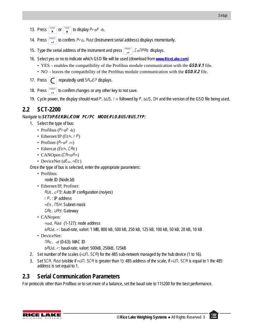
13. Press or to display .
14. Press to confirm. (Instrument serial address) displays momentarily.
15. Type the serial address of the instrument and press . displays.
16. Select yes or no to indicate which GSD file will be used (download from www.RiceLake.com)
• YES – enables the compatibility of the Profibus module communication with the GSD.V.1 file.• NO – leaves the compatibility of the Profibus module communication with the GSD.V.2 file.
17. Press repeatedly until displays.
18. Press to confirm changes or any other key to not save.
19. Cycle power, the display should read followed by and the version of the GSD file being used.
2.2 SCT-2200 Navigate to SETUP/SERIAL/COM PC/ PC MODE/FLD.BUS/ BUS.TYP:
1. Select the type of bus:
• Profibus ()• Ethernet/IP ()• Profinet ()• Ethercat ()• CANOpen ()• DeviceNet ()
Once the type of bus is selected, enter the appropriate parameters:• Profibus:
node ID (Node.Id)• Ethernet/IP, Profinet:
: Auto IP configuration (no/yes): IP address: Subnet mask: Gateway
• CANopen:(1-127): node address: baud-rate, valori: 1 MB, 800 kB, 500 kB, 250 kB, 125 kB, 100 kB, 50 kB, 20 kB, 10 kB
• DeviceNet: (0-63): MAC ID: baud-rate, valori: 500kB, 250kB, 125kB
2. Set number of the scales () for the 485 sub-network managed by the hub device (1 to 16).
3. Set (visible if is greater than 1): 485 address of the scale, if is equal to 1 the 485 address is set equal to 1.
2.3 Serial Communication ParametersFor protocols other than Profibus or to set more of a balance, set the baud rate to 115200 for the best performance.
ZERO TARE
CPRINT
© Rice Lake Weighing Systems ● All Rights Reserved 3
Fieldbus Card – Profibus, ProfiNet, EtherCat, DeviceNet, CANopen, Ethernet/IP
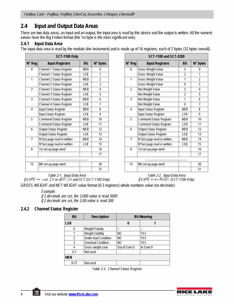
2.4 Input and Output Data AreasThere are two data areas, an input and an output, the input area is read by this device and the output is written. All the numeric values have the Big Endian format (the 1st byte is the most significant one).
2.4.1 Input Data AreaThe input data area is read by the module (the instrument) and is made up of 16 registers, each of 2 bytes (32 bytes overall).
SCT-1100 Only
N° Reg Input Registers Bit N° bytes
0 Channel 1 Status Register MSB 0
Channel 1 Status Register LSB 1
1 Channel 2 Status Register MSB 2
Channel 2 Status Register LSB 3
2 Channel 3 Status Register MSB 4
Channel 3 Status Register LSB 5
3 Channel 4 Status Register MSB 6
Channel 4 Status Register LSB 7
4 Input Status Register MSB 8
Input Status Register LSB 9
5 Command Status Register MSB 10
Command Status Register LSB 11
6 Output Status Register MSB 12
Output Status Register LSB 13
7 N°last page read or written MSB 14
N°last page read or written LSB 15
8 1st set-up page word 16
17
....................................................
15 8th set-up page word 30
31
Table 2-1. Input Data Area if >> or and SCT (SCT-1100 Only)
SCT-1100 and SCT-2200
N° Reg Input Registers Bit N° bytes
0 Gross Weight Value 3 0
Gross Weight Value 2 1
1 Gross Weight Value 1 2
Gross Weight Value 0 3
2 Net Weight Value 3 4
Net Weight Value 2 5
3 Net Weight Value 1 6
Net Weight Value 0 7
4 Input Status Register MSB 8
Input Status Register LSB 9
5 Command Status Register MSB 10
Command Status Register LSB 11
6 Output Status Register MSB 12
Output Status Register LSB 13
7 N°last page read or written MSB 14
N°last page read or written LSB 15
8 1st set-up page word 16
17
....................................................
15 8th set-up page word 30
31
Table 2-2. Input Data Areaif >> (SCT-1100 Only)
GROSS WEIGHT and NET WEIGHT value format (0-3 registers) whole numbers value (no decimals)
Example: if 3 decimals are set, the 3,000 value is read 3000if 2 decimals are set, the 3,00 value is read 300
2.4.2 Channel Status Register
Bit Description Bit Meaning
LSB 0 1
0 Weight Polarity + --1 Weight Stability NO YES2 Under load Condition NO YES3 Overload Condition NO YES4 Gross weight zone Out of Zone 0 In Zone 0
5-7 Not used
MSB
8-15 Not used
Table 2-3. Channel Status Register
4 Visit our website www.RiceLake.com
Setup
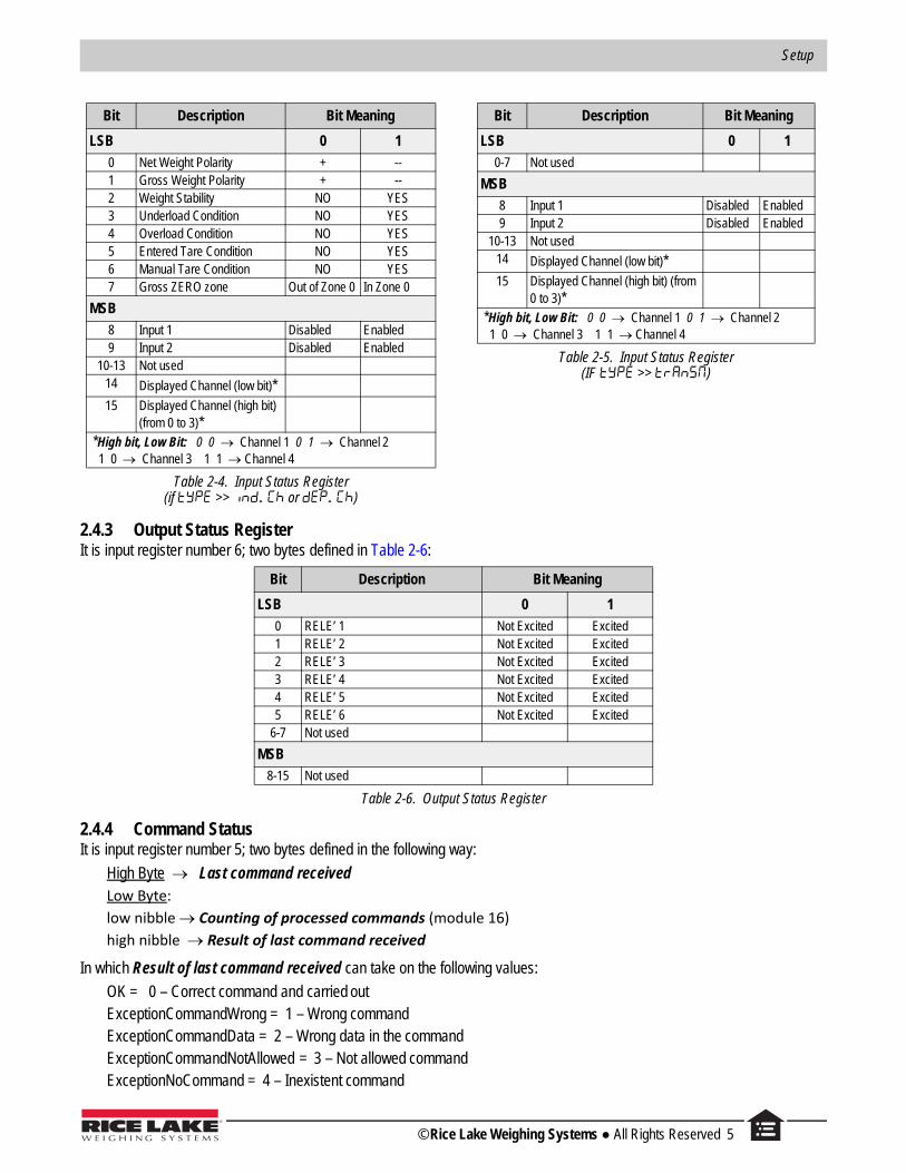
2.4.3 Output Status RegisterIt is input register number 6; two bytes defined in Table 2-6:
2.4.4 Command StatusIt is input register number 5; two bytes defined in the following way:
High Byte Last command receivedLow Byte:
low nibble Counting of processed commands (module 16)
high nibble Result of last command received
In which Result of last command received can take on the following values:
OK = 0 – Correct command and carried outExceptionCommandWrong = 1 – Wrong commandExceptionCommandData = 2 – Wrong data in the commandExceptionCommandNotAllowed = 3 – Not allowed commandExceptionNoCommand = 4 – Inexistent command
Bit Description Bit Meaning
LSB 0 1
0 RELE’ 1 Not Excited Excited1 RELE’ 2 Not Excited Excited2 RELE’ 3 Not Excited Excited3 RELE’ 4 Not Excited Excited4 RELE’ 5 Not Excited Excited5 RELE’ 6 Not Excited Excited
6-7 Not used
MSB
8-15 Not used
Table 2-6. Output Status Register
Bit Description Bit Meaning
LSB 0 1
0 Net Weight Polarity + --1 Gross Weight Polarity + --2 Weight Stability NO YES3 Underload Condition NO YES4 Overload Condition NO YES5 Entered Tare Condition NO YES6 Manual Tare Condition NO YES7 Gross ZERO zone Out of Zone 0 In Zone 0
MSB
8 Input 1 Disabled Enabled9 Input 2 Disabled Enabled
10-13 Not used14 Displayed Channel (low bit)*15 Displayed Channel (high bit)
(from 0 to 3)* *High bit, Low Bit: 0 0 Channel 1 0 1 Channel 2 1 0 Channel 3 1 1 Channel 4
Table 2-4. Input Status Register(if >> or )
Bit Description Bit Meaning
LSB 0 1
0-7 Not used
MSB
8 Input 1 Disabled Enabled9 Input 2 Disabled Enabled
10-13 Not used14 Displayed Channel (low bit)*15 Displayed Channel (high bit) (from
0 to 3)* *High bit, Low Bit: 0 0 Channel 1 0 1 Channel 2 1 0 Channel 3 1 1 Channel 4
Table 2-5. Input Status Register (IF >> )
© Rice Lake Weighing Systems ● All Rights Reserved 5

Fieldbus Card – Profibus, ProfiNet, EtherCat, DeviceNet, CANopen, Ethernet/IP
2.5 Output DataThe output data area is written by the master (is therefore read by the instrument) and is made up of 16 registers, each of 2 bytes (32 bytes overall).
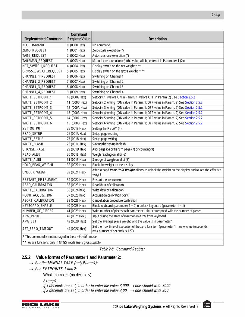
2.5.1 Command RegisterIt is the output register number 0. It is made up of two bytes and can take on the following values, which correspond to the implemented commands described in the table.
Execution of a CommandThe execution of a command is made when the contents of the Command Register varies (therefore in order to repeat the last command, first set the Command Register to the NO COMMAND value and then to the COMMAND value).
The only exceptions are the READ_SETUP, WRITE_SETUP and CHANGE_PAGE commands, which are executed even upon just the varying of Parameter 1 (page no. to be read/written). Therefore:
To read various setup pages, set the READ_SETUP command with the first page that is intended to write in Param 1, then change each time Param 1 with the new page no. to be read.
To write various pages, set the WRITE_SETUP command with the no. of the first page to be written in Param 1 and the data in registers 8-15 of the output area; then each time one varies the data of the registers 8-15 and the page no. in Param 1.
Reg No. Output Registers Bit
N° bytes
0 Command Register MSB 0
Command Register LSB 1
1 Parameter 1 3 2
Parameter 1 2 3
2 Parameter 1 1 4
Parameter 1 0 5
3 Parameter 2 3 6
Parameter 2 2 7
4 Parameter 2 1 8
Parameter 2 0 9
5 Not used 10
Not used 11
6 Not used 12
Not used 13
7 Not used 14
Not used 15
8 1st set-up page word 16
17
....................................................
15 8th set-up page word 30
31
Table 2-7. Output Data
6 Visit our website www.RiceLake.com
Setup
2.5.2 Value format of Parameter 1 and Parameter 2: For the MANUAL TARE (only Param1): For SETPOINTS 1 and 2:
Whole numbers (no decimals)Example:If 3 decimals are set, in order to enter the value 3,000 one should write 3000 If 2 decimals are set, in order to enter the value 3,00 one should write 300
Implemented CommandCommand
Register Value Description
NO_COMMAND 0 (0000 Hex) No command
ZERO_REQUEST 1 (0001 Hex) Zero scale execution (*)
TARE_REQUEST 2 (0002 Hex) Automatic tare execution (*)
TAREMAN_REQUEST 3 (0003 Hex) Manual tare execution (*) (the value will be entered in Parameter 1 (2))
NET_SWITCH_REQUEST 4 (0004 Hex) Display switch on the net weight * **
GROSS_SWITCH_REQUEST 5 (0005 Hex) Display switch on the gross weight * **
CHANNEL_1_REQUEST 6 (0006 Hex) Switching on Channel 1
CHANNEL_2_REQUEST 7 (0007 Hex) Switching on Channel 2
CHANNEL_3_REQUEST 8 (0008 Hex) Switching on Channel 3
CHANNEL_4_REQUEST 9 (0009 Hex) Switching on Channel 4
WRITE_SETPOINT_1 10 (000A Hex) Setpoint 1 (valore ON in Param. 1; valore OFF in Param. 2) See Section 2.5.2
WRITE_SETPOINT_2 11 (000B Hex) Setpoint 2 writing (ON value in Param. 1; OFF value in Param. 2) See Section 2.5.2
WRITE_SETPOINT_3 12 (000A Hex) Setpoint 3 writing (ON value in Param. 1; OFF value in Param. 2) See Section 2.5.2
WRITE_SETPOINT_4 13 (000B Hex) Setpoint 4 writing (ON value in Param. 1; OFF value in Param. 2) See Section 2.5.2
WRITE_SETPOINT_5 14 (000A Hex) Setpoint 5 writing (ON value in Param. 1; OFF value in Param. 2) See Section 2.5.2
WRITE_SETPOINT_6 15 (000B Hex) Setpoint 6 writing (ON value in Param. 1; OFF value in Param. 2) See Section 2.5.2
SET_OUTPUT 25 (0019 Hex) Setting the RELAY (4)
READ_SETUP 26 (001A Hex) Setup page reading
WRITE_SETUP 27 (001B Hex) Setup page writing
WRITE_FLASH 28 (001C Hex) Saving the set-up in flash
CHANGE_PAGE 29 (001D Hex) Alibi page (5) or transm page (7) or counting(9)
READ_ALIBI 30 (001E Hex) Weigh reading on alibi (6)
WRITE_ALIBI 31 (001F Hex) Storage of weigh on alibi (5)
HOLD_PEAK_WEIGHT 32 (0020 Hex) Block the weight on the display
UNLOCK_WEIGHT 33 (0021 Hex)After second Peak Hold Weight allows to unlock the weight on the display and to see the effective weight
RESTART_INSTRUMENT 34 (0022 Hex) Restart the instrument
READ_CALIBRATION 35 (0023 Hex) Read data of calibration
WRITE_CALIBRATION 36 (0024 hex) Write data of calibration
POINT_ACQUISITION 37 (0025 hex) Acquisition calibration point
ABORT_CALIBRATION 38 (0026 Hex) Cancellation procedure calibration
KEYBOARD_ENABLE 40 (0028 Hex) Block keyboard (parameter 1 = 0) o unlock keyboard (parameter 1 = 1)
NUMBER_OF_PIECES 41 (0029 Hex) Write number of pieces with parameter 1 that correspond with the number of pieces
APW_INPUT 42 (002° Hex ) Input during the state of insertion in APW from keyboard
APW_SET 43 (002B Hex) Set the average piece weight; and the value is in parameter 1
SET_ZERO_TIMEOUT 44 (002C Hex)Set the max time of execution of the zero function (parameter 1 = new value in seconds, max number of seconds is 127)
* This command is not managed in the mode.
** Active functions only in NTGS mode (net / gross switch)
Table 2-8. Command Register
© Rice Lake Weighing Systems ● All Rights Reserved 7
Fieldbus Card – Profibus, ProfiNet, EtherCat, DeviceNet, CANopen, Ethernet/IP
2.5.3 Setting of the RelaysThe status of the relays is settable using Parameter 1:
Parameter 1:
bit 0 RELAY 1 in which bit 0 = 1 RELAY 1 CLOSED; bit 0 = 0 RELAY 1 OPENbit 1 RELAY 2 in which bit 1 = 1 RELAY 2 CLOSED; bit 1 = 0 RELAY 2 OPEN
Value format of Parameter 1 and Parameter 2 for the RELAYS: Bit configuration
In the case a relay is linked to a setpoint, the command, relative to that relay, is ignored.
The writing of the setpoint values does not cause the automatic flash saving, but are set temporarily. In order to save these in flash one should execute the WRITE_FLASH command.
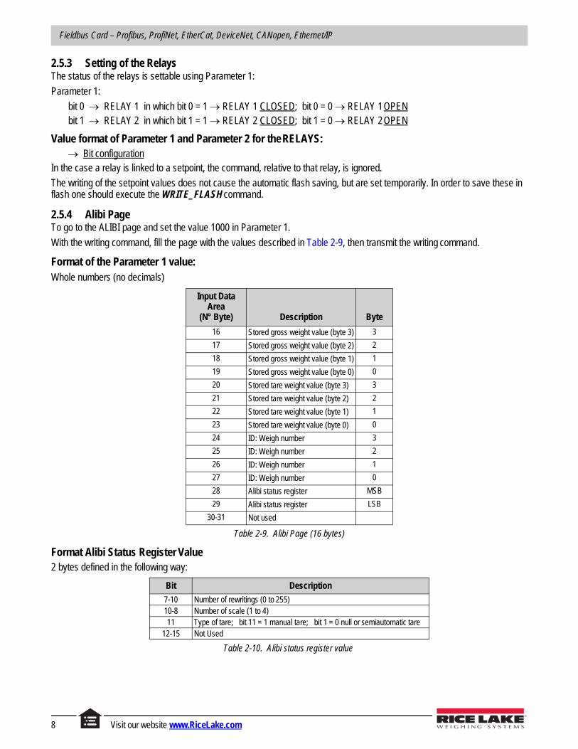
2.5.4 Alibi PageTo go to the ALIBI page and set the value 1000 in Parameter 1.
With the writing command, fill the page with the values described in Table 2-9, then transmit the writing command.
Format of the Parameter 1 value:Whole numbers (no decimals)
Format Alibi Status Register Value2 bytes defined in the following way:
Input Data Area
(N° Byte) Description Byte
16 Stored gross weight value (byte 3) 3
17 Stored gross weight value (byte 2) 2
18 Stored gross weight value (byte 1) 1
19 Stored gross weight value (byte 0) 0
20 Stored tare weight value (byte 3) 3
21 Stored tare weight value (byte 2) 2
22 Stored tare weight value (byte 1) 1
23 Stored tare weight value (byte 0) 0
24 ID: Weigh number 3
25 ID: Weigh number 2
26 ID: Weigh number 1
27 ID: Weigh number 0
28 Alibi status register MSB
29 Alibi status register LSB
30-31 Not used
Table 2-9. Alibi Page (16 bytes)
Bit Description
7-10 Number of rewritings (0 to 255)10-8 Number of scale (1 to 4)11 Type of tare; bit 11 = 1 manual tare; bit 1 = 0 null or semiautomatic tare
12-15 Not Used
Table 2-10. Alibi status register value
8 Visit our website www.RiceLake.com

Setup
2.5.5 Weigh Reading on AlibiTo read a weight stored in the Alibi, set the rewriting number in Parameter 1 and the weight number (ID) in Parameter 2. The command automatically executes the change on the Alibi page.
Format of the Parameter 1 and Parameter 2 values with whole numbers (no decimals)
2.5.6 Transm Page (only if >> )To go to the Transm page, set a value 2000 in Parameter 1. With the writing command, fill the page with the values in Table 2-11, then transmit the writing command. After the start-up of the indicator, the value 2000 is set automatically as the last page read.
Format of the Parameter 1 value with whole numbers (no decimals)
Commands Performed in the Mode TransmModbus/Profibus Zero command (1) in Transm mode: parameter 1 is to be set to a non-zero value to indicate the scale channel that is to be zeroed.
Modbus/Profibus Tare command (2) in Transm mode: parameter 1 is to be set to a non-zero value to indicate the scale channel that is to be tared.
Modbus/Profibus Preset tare command (3) in Transm mode: parameter 2 is to be set to a non-zero value to indicate the scale channel that is to be tared.
Input Data Area(N° Byte) Description Byte Description Byte
Date 2000 Net 2001 Tare 2002 -- Net/Tare 2003 --
16 Channel 1 weight value Ch 1 net weight Ch 1 tare weight 3 Ch 1 net weight 1
17 Channel 1 weight value Ch 1 net weight Ch 1 tare weight 2 Ch 1 net weight 0
18 Channel 1 weight value Ch 1 net weight Ch 1 tare weight 1 Ch 1 tare weight 1
19 Channel 1 weight value Ch 1 net weight Ch 1 tare weight 0 Ch 1 tare weight 0
20 Channel 2 weight value Ch 2 net weight Ch 2 tare weight 3 Ch 2 net weight 1
21 Channel 2 weight value Ch 2 net weight Ch 2 tare weight 2 Ch 2 net weight 0
22 Channel 2 weight value Ch 2 net weight Ch 2 tare weight 1 Ch 2 tare weight 1
23 Channel 2 weight value Ch 2 net weight Ch 2 tare weight 0 Ch 2 tare weight 0
24 Channel 3 weight value Ch 3 net weight Ch 3 tare weight 3 Ch 3 net weight 1
25 Channel 3 weight value Ch 3 net weight Ch 3 tare weight 2 Ch 3 net weight 0
26 Channel 3 weight value Ch 3 net weight Ch 3 tare weight 1 Ch 3 tare weight 1
27 Channel 3 weight value Ch 3 net weight Ch 3 tare weight 0 Ch 3 tare weight 0
28 Channel 4 weight value Ch 4 net weight Ch 4 tare weight 3 Ch 4 net weight 1
29 Channel 4 weight value Ch 4 net weight Ch 4 tare weight 2 Ch 4 net weight 0
30 Channel 4 weight value Ch 4 net weight Ch 4 tare weight 1 Ch 4 tare weight 1
31 Channel 4 weight value Ch 4 net weight Ch 4 tare weight 0 Ch 4 tare weight 0
Table 2-11. Transm Page (16 bytes)
© Rice Lake Weighing Systems ● All Rights Reserved 9
Fieldbus Card – Profibus, ProfiNet, EtherCat, DeviceNet, CANopen, Ethernet/IP
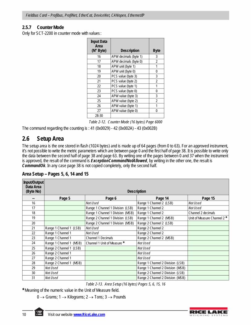
2.5.7 Counter ModeOnly for SCT-2200 in counter mode with values :
The command regarding the counting is : 41 (0x0029) - 42 (0x002A) - 43 (0x002B)
2.6 Setup AreaThe setup area is the one stored in flash (1024 bytes) and is made up of 64 pages (from 0 to 63). For an approved instrument, it’s not possible to write the metric parameters which are between page 0 and the first half of page 38. It is possible to write only the data between the second half of page 38 and page 63. By writing one of the pages between 0 and 37 when the instrument is approved, the result of the command is ExceptionCommandNotAllowed, by writing in the other one, the result is CommandOk. In any case page 38 is not copied completely, only the second half.
Area Setup – Pages 5, 6, 14 and 15
* Meaning of the numeric value in the Unit of Measure field.
0 Grams; 1 Kilograms; 2 Tons; 3 Pounds
Input Data Area
(N° Byte) Description Byte
16 APW decimals (byte 1) 317 APW decimals (byte 0) 218 APW unit (byte 1) 119 APW unit (byte 0) 020 PCS value (byte 3) 321 PCS value (byte 2) 222 PCS value (byte 1) 123 PCS value (byte 0) 024 APW value (byte 3) 325 APW value (byte 2) 226 APW value (byte 1) 127 APW value (byte 0) 0
28-30
Table 2-12. Counter Mode (16 bytes) Page 6000
Input/Output Data Area(Byte No) Description
-- Page 5 Page 6 Page 14 Page 1516 Not Used Range 1 Channel 2 (LSB) Not Used17 Range 1 Channel 1 Division (LSB) Range 1 Channel 2 Not Used18 Range 1 Channel 1 Division (MSB) Range 1 Channel 2 Channel 2 decimals19 Range 2 Channel 1 Division (LSB) Range 1 Channel 2 (MSB) Unit of Measure Channel 2 *20 Range 2 Channel 1 Division (MSB) Range 2 Channel 2 (LSB)21 Range 1 Channel 1 (LSB) Not Used Range 2 Channel 222 Range 1 Channel 1 Not Used Range 2 Channel 223 Range 1 Channel 1 Channel 1 Decimals Range 2 Channel 2 (MSB)24 Range 1 Channel 1 (MSB) Channel 1 Unit of Measure * Not Used25 Range 2 Channel 1 (LSB) Not Used26 Range 2 Channel 1 Not Used27 Range 2 Channel 1 Not Used28 Range 2 Channel 1 (MSB) Range 1 Channel 2 Division (LSB)29 Not Used Range 1 Channel 2 Division (MSB)30 Not Used Range 2 Channel 2 Division (LSB)31 Not Used Range 2 Channel 2 Division (MSB)
Table 2-13. Area Setup (16 bytes) Pages 5, 6, 15, 16
10 Visit our website www.RiceLake.com

Setup
Area Setup – Pages 22, 23, 31 and 32
* Meaning of the numeric value in the Unit of Measure field.
0 Grams; 1 Kilograms; 2 Tons; 3 Pounds
2.7 Calibration SequenceThe following tables contain metrological data, that is possible to read/write.
Unit of measure
0 g; 1 kg; 2 T; 3 L
Input/Output Data Area(Byte No) Description
-- Page 22 Page 23 Page 31 Page 3216 Range 2 Channel 3 Not used17 Range 2 Channel 3 Not used18 Range 2 Channel 3 (MSB) Range 1 channel 4 Division (LSB)19 Not Used Range 1 channel 4 Division (MSB)20 Not Used Range 2 channel 4 Division (LSB)21 Not Used Range 2 channel 4 Division (MSB)22 Not Used Range 1 Channel 4 (LSB) Not used23 Range 1 Channel 3 Division (LSB) Range 1 Channel 4 Not used24 Range 1 Channel 3 Division (MSB) Range 1 Channel 4 Channel 4 decimals25 Range 2 Channel 3 Division (LSB) Range 1 Channel 4 (MSB) Channel 4 unit of measure *26 Range 2 Channel 3 Division (MSB) Range 2 Channel 4 (LSB)27 Range 1 Channel 3 (LSB) Not Used Range 2 Channel 428 Range 1 Channel 3 Not Used Range 2 Channel 429 Range 1 Channel 3 Channel 3 decimals Range 2 Channel 4 (MSB)30 Range 1 Channel 3 (MSB) Channel 3 unit of measure * Not Used31 Range 2 Channel 3 (LSB) Not Used
Table 2-14. Area Setup (16 bytes) pages 22, 23, 31, 32
Input Data Area
(N° Byte) Description Byte
16 Unit Of Measure 117 Unit Of Measure 018 1st Range Division 119 1st Range Division 020 2nd Range Division 121 2nd Range Division 022 Decimal 123 Decimal 024 1st Range Capacity 325 1st Range Capacity 226 1st Range Capacity 127 1st Range Capacity 028 2nd Range Capacity29 2nd Range Capacity30 2nd Range Capacity31 2nd range capacity
Table 2-15. Metrological Data, Page 5000 (16 byte)
© Rice Lake Weighing Systems ● All Rights Reserved11
Fieldbus Card – Profibus, ProfiNet, EtherCat, DeviceNet, CANopen, Ethernet/IP
Input Data Area
(N° Byte) Description Byte
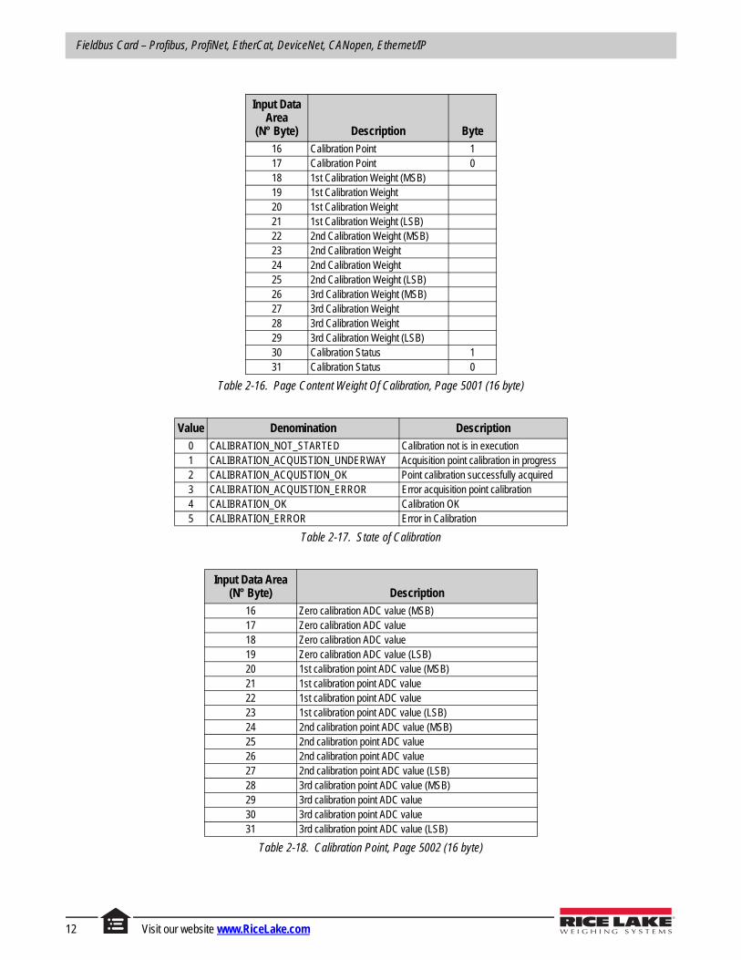
16 Calibration Point 117 Calibration Point 018 1st Calibration Weight (MSB)19 1st Calibration Weight20 1st Calibration Weight21 1st Calibration Weight (LSB)22 2nd Calibration Weight (MSB)23 2nd Calibration Weight24 2nd Calibration Weight25 2nd Calibration Weight (LSB)26 3rd Calibration Weight (MSB)27 3rd Calibration Weight28 3rd Calibration Weight29 3rd Calibration Weight (LSB)30 Calibration Status 131 Calibration Status 0
Table 2-16. Page Content Weight Of Calibration, Page 5001 (16 byte)
Value Denomination Description
0 CALIBRATION_NOT_STARTED Calibration not is in execution1 CALIBRATION_ACQUISTION_UNDERWAY Acquisition point calibration in progress2 CALIBRATION_ACQUISTION_OK Point calibration successfully acquired3 CALIBRATION_ACQUISTION_ERROR Error acquisition point calibration4 CALIBRATION_OK Calibration OK5 CALIBRATION_ERROR Error in Calibration
Table 2-17. State of Calibration
Input Data Area(N° Byte) Description
16 Zero calibration ADC value (MSB)17 Zero calibration ADC value18 Zero calibration ADC value19 Zero calibration ADC value (LSB)20 1st calibration point ADC value (MSB)21 1st calibration point ADC value22 1st calibration point ADC value23 1st calibration point ADC value (LSB)24 2nd calibration point ADC value (MSB)25 2nd calibration point ADC value26 2nd calibration point ADC value27 2nd calibration point ADC value (LSB)28 3rd calibration point ADC value (MSB)29 3rd calibration point ADC value30 3rd calibration point ADC value31 3rd calibration point ADC value (LSB)
Table 2-18. Calibration Point, Page 5002 (16 byte)
12 Visit our website www.RiceLake.com
Setup
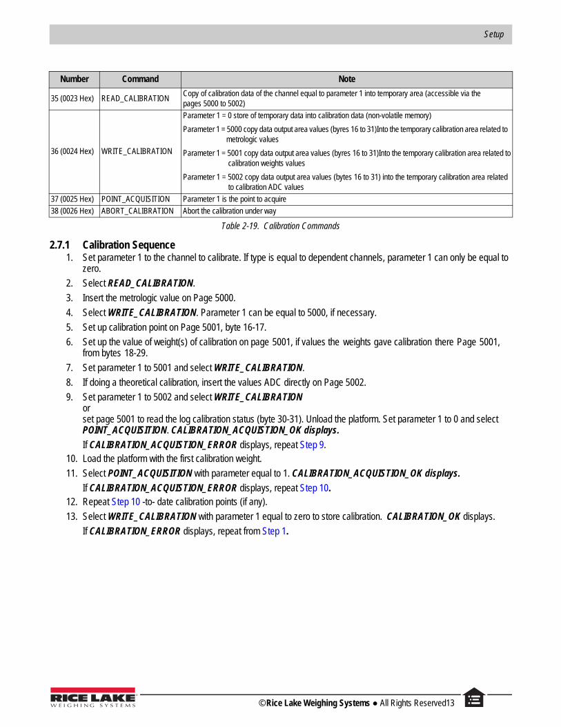
2.7.1 Calibration Sequence1. Set parameter 1 to the channel to calibrate. If type is equal to dependent channels, parameter 1 can only be equal to
zero.
2. Select READ_CALIBRATION.
3. Insert the metrologic value on Page 5000.
4. Select WRITE_CALIBRATION. Parameter 1 can be equal to 5000, if necessary.
5. Set up calibration point on Page 5001, byte 16-17.
6. Set up the value of weight(s) of calibration on page 5001, if values the weights gave calibration there Page 5001, from bytes 18-29.
7. Set parameter 1 to 5001 and select WRITE_CALIBRATION.
8. If doing a theoretical calibration, insert the values ADC directly on Page 5002.
9. Set parameter 1 to 5002 and select WRITE_CALIBRATIONor set page 5001 to read the log calibration status (byte 30-31). Unload the platform. Set parameter 1 to 0 and select POINT_ACQUISITION. CALIBRATION_ACQUISTION_OK displays.
If CALIBRATION_ACQUISTION_ERROR displays, repeat Step 9.10. Load the platform with the first calibration weight.
11. Select POINT_ACQUISITION with parameter equal to 1. CALIBRATION_ACQUISTION_OK displays.
If CALIBRATION_ACQUISTION_ERROR displays, repeat Step 10. 12. Repeat Step 10 -to- date calibration points (if any).
13. Select WRITE_CALIBRATION with parameter 1 equal to zero to store calibration. CALIBRATION_OK displays.
If CALIBRATION_ERROR displays, repeat from Step 1.
Number Command Note
35 (0023 Hex) READ_CALIBRATIONCopy of calibration data of the channel equal to parameter 1 into temporary area (accessible via thepages 5000 to 5002)
36 (0024 Hex) WRITE_CALIBRATION
Parameter 1 = 0 store of temporary data into calibration data (non-volatile memory)
Parameter 1 = 5000 copy data output area values (byres 16 to 31)Into the temporary calibration area related to metrologic values
Parameter 1 = 5001 copy data output area values (byres 16 to 31)Into the temporary calibration area related to calibration weights values
Parameter 1 = 5002 copy data output area values (bytes 16 to 31) into the temporary calibration area related to calibration ADC values
37 (0025 Hex) POINT_ACQUISITION Parameter 1 is the point to acquire
38 (0026 Hex) ABORT_CALIBRATION Abort the calibration under way
Table 2-19. Calibration Commands
© Rice Lake Weighing Systems ● All Rights Reserved13
Fieldbus Card – Profibus, ProfiNet, EtherCat, DeviceNet, CANopen, Ethernet/IP
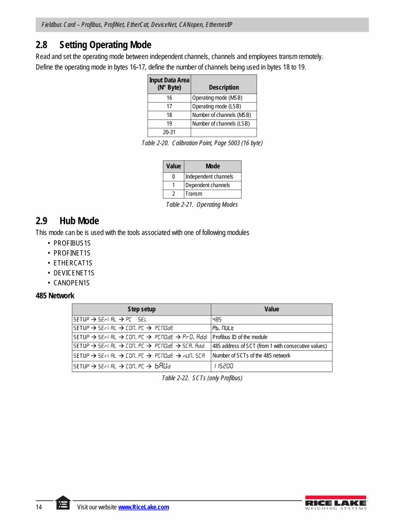
2.8 Setting Operating ModeRead and set the operating mode between independent channels, channels and employees transm remotely.
Define the operating mode in bytes 16-17, define the number of channels being used in bytes 18 to 19.
2.9 Hub ModeThis mode can be is used with the tools associated with one of following modules
• PROFIBUS1S• PROFINET1S• ETHERCAT1S• DEVICENET1S• CANOPEN1S
485 Network
Input Data Area(N° Byte) Description
16 Operating mode (MSB)
17 Operating mode (LSB)
18 Number of channels (MSB)
19 Number of channels (LSB)
20-31
Table 2-20. Calibration Point, Page 5003 (16 byte)
Value Mode
0 Independent channels
1 Dependent channels
2 Transm
Table 2-21. Operating Modes
Step setup Value
ETU
ETU
ETU Profibus ID of the module
ETU 485 address of SCT (from 1 with consecutive values)
ETU Number of SCTs of the 485 network
ETU
Table 2-22. SCTs (only Profibus)
14 Visit our website www.RiceLake.com

Setup
Parameters dependent from selected protocol: read paragraph 1.2
Profinet – the name of the node to be used in Profinet project associated with the master node of the network is given by Dini- <IP4>, where IP4 is the last byte of the IP address entered in the configuration of SCT, even if the self-configuration of the IP address is used.
Example: IP = 192.168.1.10, the node name is Dini-010.
Verify 485 network1. From the configuration menu select The scale will execute a continuous cycle to check if the scales
on the network work.
• Value 1 means that the selected scale is on-line.• Value 0 means that the selected scale is off-line.
2. Using arrow keys the instrument enters in the manual scan.
3. Press C key to exit. At connection 485 network displays briefly, followed by . When the Profibus master connects the yellow led of the module will turn on.
2.10 Output DataThe area of Profibus output is composed of 32 bytes as indicated in Table 2-24.
The Command Register structure:
• MSB: to which scale of the 485 network send the data of the area (1 scale 1, 2 scale 2, …)• LSB: command, ignored by hub module.
The module will send to the selected scale the whole area as received by the Profibus master, but with the MSB byte of the Command Register equal to zero.
Step setup Value
5 BUS
: Profibus : Ethernet/IP : Profinet : Ethercat : CANopen : DeviceNet
Other parameters depending on the protocol selected N.A Balance number on the 485 network D Address 485 of the SCT (from 1 consecutive value) AD
Table 2-23. SCT’s
Byte Data
1 Scale Command register (MSB) to which scale send the command (7F Broadcast)
2 Scale Command register (LSB) command
3 Data
… …
32 Data
Table 2-24. Output Data Area
© Rice Lake Weighing Systems ● All Rights Reserved15

Fieldbus Card – Profibus, ProfiNet, EtherCat, DeviceNet, CANopen, Ethernet/IP
Commands with MSB greater than 0x6F will be managed by the hub module.
Commands in broadcast, do not provide feedback from the balance, they are actually carried out by all the scales. To ensure that they execute, control the outcome of the controls and counter balances.
2.11 Input DataThe Input Data area can be filled with different pages.
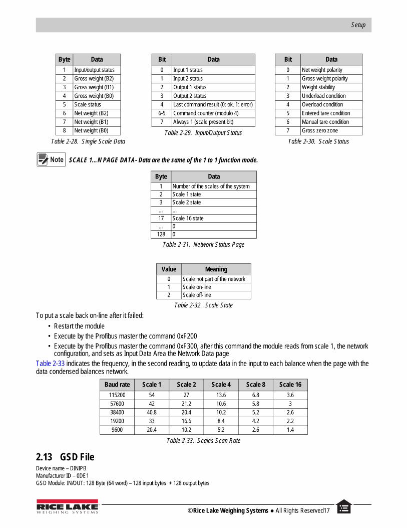
2.12 Network Page DataThis page has the structure seen in Table 2-28.
Byte Data
1 Scale 1 data (byte 1)
2 Scale 1 data (byte 2)
3 Scale 1 data (byte 3)
4 Scale 1 data (byte 4)
5 Scale 1 data (byte 5)
6 Scale 1 data (byte 6)
7 Scale 1 data (byte 7)
8 Scale 1 data (byte 8)
9 Scale 2 data (byte 1)
10 Scale 2 data (byte 2)
11 Scale 2 data (byte 3)
12 Scale 2 data (byte 4)
13 Scale 2 data (byte 5)
14 Scale 2 data (byte 6)
15 Scale 2 data (byte 7)
16 Scale 2 data (byte 8)
… …
121 Scale 16 data (byte 1)
Byte Data
122 Scale 16 data (byte 2)
123 Scale 16 data (byte 3)
124 Scale 16 data (byte 4)
125 Scale 16 data (byte 5)
126 Scale 16 data (byte 6)
127 Scale 16 data (byte 7)
128 Scale 16 data (byte 8)
Byte Data
Table 2-27. Network Page Data
Command (Hex) Description
F000 Fill in the Input Data Area with scale data system (Table 2-38 on page 19)
F001 Fill in the Input Data Area with the data received from the scale 1
F002 Fill in the Input Data Area with the data received from the scale 2
… …
F010 Fill Input Data Area with scale 16 data
F100 Fill Input Data Area with status data of the system
F200 Scan of the 485 network. Useful if some scales are not connected and want check if they returned on-line.
F300 Rereading network settings from the scale 1 and scanning network. It also allows the change in the number of scales in the network, whether it varies in scale 1.
7Fxx Enter the Output data area in the broadcast, in all scales of the subsystem 485 (with Modbus address zero)
Table 2-25. Commands
PageProfibus Command (HEX) to
Change Page
Network data page F000
Scale 1 data F001
... …
Scale 16 data F010
Network status F100
Table 2-26. Input Data Area
16 Visit our website www.RiceLake.com
Setup
Byte Data
1 Input/output status
2 Gross weight (B2)
3 Gross weight (B1)
4 Gross weight (B0)
5 Scale status
6 Net weight (B2)
7 Net weight (B1)
8 Net weight (B0)
Table 2-28. Single Scale Data
Bit Data
0 Input 1 status
1 Input 2 status
2 Output 1 status
3 Output 2 status
4 Last command result (0: ok, 1: error)
6-5 Command counter (modulo 4)
7 Always 1 (scale present bit)
Table 2-29. Input/Output Status
Bit Data
0 Net weight polarity
1 Gross weight polarity
2 Weight stability
3 Underload condition
4 Overload condition
5 Entered tare condition
6 Manual tare condition
7 Gross zero zone
Table 2-30. Scale Status
SCALE 1…N PAGE DATA- Data are the same of the 1 to 1 function mode.
To put a scale back on-line after it failed:
• Restart the module• Execute by the Profibus master the command 0xF200• Execute by the Profibus master the command 0xF300, after this command the module reads from scale 1, the network
configuration, and sets as Input Data Area the Network Data pageTable 2-33 indicates the frequency, in the second reading, to update data in the input to each balance when the page with the data condensed balances network.
2.13 GSD File Device name – DINIPBManufacturer ID – 0DE1GSD Module: IN/OUT: 128 Byte (64 word) – 128 input bytes + 128 output bytes
Byte Data
1 Number of the scales of the system2 Scale 1 state3 Scale 2 state… …17 Scale 16 state… 0
128 0
Table 2-31. Network Status Page
Value Meaning
0 Scale not part of the network1 Scale on-line2 Scale off-line
Table 2-32. Scale State
Baud rate Scale 1 Scale 2 Scale 4 Scale 8 Scale 16
115200 54 27 13.6 6.8 3.6
57600 42 21.2 10.6 5.8 3
38400 40.8 20.4 10.2 5.2 2.6
19200 33 16.6 8.4 4.2 2.2
9600 20.4 10.2 5.2 2.6 1.4
Table 2-33. Scales Scan Rate
Note
© Rice Lake Weighing Systems ● All Rights Reserved17
Fieldbus Card – Profibus, ProfiNet, EtherCat, DeviceNet, CANopen, Ethernet/IP
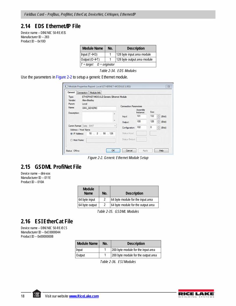
2.14 EDS Ethernet/IP File Device name – DINI NIC 50-RE/EISManufacturer ID – 283Product ID – 0x10D
Use the parameters in Figure 2-2 to setup a generic Ethernet module.
Figure 2-2. Generic Ethernet Module Setup
2.15 GSDML ProfiNet File Device name – dini-xxxManufacturer ID – 011EProduct ID – 010A
2.16 ESI EtherCat File Device name – DINI NIC 50-RE/ECSManufacturer ID – 0xE0000044Product ID – 0x0000000B
Module Name No. Description
Input (TO) 1 128 byte input area module
Output (OT) 1 128 byte output area module
T = target O = originator
Table 2-34. EDS Modules
Module Name No. Description
64 byte input 2 64 byte module for the input area
64 byte output 2 64 byte module for the output area
Table 2-35. GSDML Modules
Module Name No. Description
Input 1 200 byte module for the input area
Output 1 200 byte module for the output area
Table 2-36. ESI Modules
18 Visit our website www.RiceLake.com
Setup
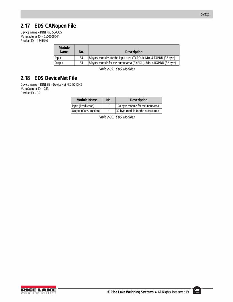
2.17 EDS CANopen File Device name – DINI NIC 50-COSManufacturer ID – 0x00000044Product ID – 1541540
2.18 EDS DeviceNet File Device name – DINI Slim-DeviceNet NIC 50-DNSManufacturer ID – 283Product ID – 35
Module Name No. Description
Input 64 8 bytes modules for the input area (TXPDU). Min. 4 TXPDU (32 byte)
Output 64 8 bytes module for the output area (RXPDU). Min. 4 RXPDU (32 byte)
Table 2-37. EDS Modules
Module Name No. Description
Input (Production) 1 128 byte module for the input area
Output (Consumption) 1 32 byte module for the output area
Table 2-38. EDS Modules
© Rice Lake Weighing Systems ● All Rights Reserved19

Fieldbus Card – Profibus, ProfiNet, EtherCat, DeviceNet, CANopen, Ethernet/IP
20 Visit our website www.RiceLake.com
3.0 TroubleshootingMessages displayed by the SCT when errors are present.
3.1 ProfibusAt the first interrogation SCT by the module, the display shows the message PB.CONN, then there is no longer any message for the Profibus.
When the Profibus master connects, the yellow LED module illuminates.
3.2 Other FieldbusAs soon as it is available to SCT, this displays the firmware version of the Hub in the form fr.xx.yy (where xx.yy is the release).
At the first interrogation SCT by the module the display shows the message .
When communication between the module Hub and Fieldbus network is operational, displays.
If there is an error, and the error code alternates on the display.
If there is communication between the module and the SCT Hub, flashes on the display.
Message Description
No connection received from module Hub after 30 second since system start
Firmware version of the module hub
Start the communication between hub module and scale
Communication on Fieldbus network configured and running
Error state, see Table 3-2.
Table 3-1. Error Messages
Code Description
1000 Fatal error in Hub module
1001Inconsistency between protocol type selected and the one managed by the Hub moduleExample: Hub type DeviceNet module with Profinet protocol selected on SCT
1-18 Other fatal error in Hub module
000001 Unrecoverable error module Hub, see Table 3-3
Table 3-2. Error Code
Code Description
000140 General network error
000141 Connection closed
000142 Time-out connection
000143 Isolated network
000144 Duplicated node
000145 Network cable disconnected
Table 3-3. Error of Network


230 W. Coleman St. • Rice Lake, WI 54868 • USAU.S. 800-472-6703 • Canada/Mexico 800-321-6703 • International 715-234-9171 • Europe +31 (0)26 472 1319
Rice Lake Weighing Systems is an ISO 9001 registered company. © Rice Lake Weighing Systems Specifications subject to change without notice.
www.ricelake.comNovember 30, 2017 PN 183523