field sampling plan for - nrc.govfield sampling plan (fsp) u.s. department of energy, west valley...
TRANSCRIPT
FIELD SAMPLING PLAN
for
TASK ORDER 4 WEST VALLEY DEMONSTRATION PROJECT
ENVIRONMENTAL CHARACTERIZATION SERVICES
WEST VALLEY, NEW YORK
SEC-FSP Rev. 0
June 2012
Prepared for: U.S. Department of Energy West Valley Demonstration Project (WVDP) Environmental Characterization Services (ECS) West Valley, New York Prepared by: Safety and Ecology Corporation (SEC) 2800 Solway Road Knoxville, TN 37931

FIELD SAMPLING PLAN for TASK ORDER 4 WEST VALLEY DEMONSTRATION PROJECT ENVIRONMENTAL CHARACTERIZATION SERVICES WEST VALLEY, NEW YORK SEC-FSP Rev. 0 June 2012 Prepared for: U.S. Department of Energy West Valley Demonstration Project (WVDP) Environmental Characterization Services (ECS) West Valley, New York Prepared by: Safety and Ecology Corporation (SEC) 2800 Solway Road Knoxville, TN 37931

Task Order 4 Field Sampling Plan (FSP) – Rev. 0
June 2012 iii
Field Sampling Plan (FSP) U.S. Department of Energy,
West Valley Demonstration Project Environmental Characterization Services
West Valley, New York Contract No.: DE-EM0001242
FSP APPROVALS
By their specific signature, the undersigned certify that they prepared, reviewed, or provided comments on this Field Sampling Plan for the DOE West Valley Demonstration Project, Environmental Characterization Services, and West Valley, New York. PREPARED BY: June 5, 2012 Geologist Date Diana Tremaine
June 5, 2012 Independent Technical Reviewer Date James Turner APPROVED BY: June 5, 2012 Corporate Quality Assurance Manager Date Darrell Srdoc June 4, 2012 Program Manager Date Andrew Lombardo, CHP June 5, 2012 Project Manager Date Steven Green, CHP, PMP TBD by PM/RM Effective Date

Task Order 4 Field Sampling Plan (FSP) – Rev. 0
June 2012 v
TABLE OF CONTENTS
LIST OF APPENDICES ................................................................................................................ vi LIST OF TABLES ........................................................................................................................ vii ABBREVIATIONS, ACRONYMS, AND SYMBOLS ................................................................ ix EXECUTIVE SUMMARY ........................................................................................................... xi
1.0 INTRODUCTION ........................................................................................................... 1-1
1.1 Site Description .................................................................................................... 1-1
1.2 Project Description ............................................................................................... 1-1
1.3 Objective .............................................................................................................. 1-3
1.4 Scope .................................................................................................................... 1-5
1.5 Radionuclides of Interest and Cleanup Goals ...................................................... 1-5
2.0 ENVIRONMENT, SAFETY, HEALTH, QUALITY, AND RADIATION PROTECTION ................................................................................................................. 2-1
3.0 ROLES AND RESPONSIBILITIES ............................................................................... 3-1
3.1 Key Project Personnel .......................................................................................... 3-1
3.1.1 SEC Project Manager ............................................................................... 3-1
3.1.2 Radiological Engineer .............................................................................. 3-1
3.1.3 SEC Environmental Safety and Health (ES&H) Manager ...................... 3-1
3.1.4 Site Geologist/QC Coordinator ................................................................ 3-2
3.1.5 Subcontractor Field Lead ......................................................................... 3-2
4.0 FIELD ACTIVITIES ....................................................................................................... 4-1
4.1 Clearing and Grubbing ......................................................................................... 4-1
4.2 Gamma Walkover Survey (GWS) ....................................................................... 4-1
4.3 Sample Collection ................................................................................................ 4-3
4.3.1 Direct-push Drilling for Sample Collection ............................................. 4-4
4.3.2 Systematic Soil Sampling ........................................................................ 4-5
4.3.3 Biased Soil Sampling ............................................................................... 4-8
4.4 Civil Surveying Requirements ............................................................................. 4-9
4.5 Decontamination .................................................................................................. 4-9
4.6 Investigation Derived Waste (IDW) .................................................................. 4-10
5.0 REFERENCE AREAS..................................................................................................... 5-1
6.0 QUALITY ASSURANCE/QUALITY CONTROL ........................................................ 6-1
6.1 Radiological Instrument Calibration, Testing and Maintenance Quality Requirements ....................................................................................................... 6-2
6.2 Gamma Walkover Survey Quality Assurance/Quality Control Requirements .... 6-3
6.3 Field Documentation ............................................................................................ 6-5
6.3.1 Field Logbooks ........................................................................................ 6-5
6.3.2 Photographs.............................................................................................. 6-6
6.4 Sample Quality Assurance/Quality Control ......................................................... 6-6
6.4.1 Sample Collection .................................................................................... 6-6
6.4.2 Sample-Numbering System ..................................................................... 6-7
6.4.3 Sample Labeling ...................................................................................... 6-7

Task Order 4 Field Sampling Plan (FSP) – Rev. 0
June 2012 vi
6.4.4 Sample Packaging .................................................................................... 6-8
6.4.5 Additional Requirements for Samples Classified as Radioactive Materials .................................................................................................. 6-8
6.4.6 Chain of Custody Records ....................................................................... 6-9
6.4.7 Sample Shipping .................................................................................... 6-10
6.4.8 Laboratory Receipt of Sample Forms .................................................... 6-10
6.4.9 Sample Documentation Process ............................................................. 6-10
6.4.10 Corrections to Documentation ............................................................... 6-10
6.5 Laboratory and Data Quality Assurance/Quality Control ................................. 6-11
6.5.1 Laboratory Analysis ............................................................................... 6-11
6.5.2 Reporting................................................................................................ 6-11
6.6 Data Verification and Validation ....................................................................... 6-13
6.6.1 Data Verification .................................................................................... 6-13
6.6.2 Data Validation ...................................................................................... 6-13
6.7 Data Quality Objectives/Indicators .................................................................... 6-14
6.7.1 Precision ................................................................................................. 6-14
6.7.2 Accuracy ................................................................................................ 6-16
6.7.3 Representativeness ................................................................................. 6-17
6.7.4 Completeness ......................................................................................... 6-17
6.7.5 Comparability ........................................................................................ 6-17
7.0 REFERENCES ................................................................................................................ 7-1
LIST OF APPENDICES
APPENDIX A: Gamma Walkover Procedure APPENDIX B: Geoprobe Procedure APPENDIX C: Soil Sampling Procedure APPENDIX D: Laboratory Requests and Chain of Custody APPENDIX E: Sample Log Sheet APPENDIX F: Cooler Receipt Checklist

Task Order 4 Field Sampling Plan (FSP) – Rev. 0
June 2012 vii
LIST OF TABLES
Table 1-1 Phase 1 Cleanup Goals [picocuries per gram (pCi/g)] ............................................. 1-6 Table 1-2 Twelve Radionuclides of Potential Interest .............................................................. 1-7 Table 4-1 Estimated Scanning Minimum Detectable Activities (MDCs) ................................ 4-2 Table 6-1 Sample Identification ............................................................................................... 6-7 Table 6-2 Analytical Methods and Minimum Volumes ......................................................... 6-12
Table 6-3 Electronic Deliverables .......................................................................................... 6-13

Task Order 4 Field Sampling Plan (FSP) – Rev. 0
June 2012 ix
ABBREVIATIONS, ACRONYMS, AND SYMBOLS
ALARA As Low As Reasonably Achievable ASME American Society of Mechanical Engineers bgs below ground surface CAP Contractor Assurance Program CFR Code of Federal Regulations CG Cleanup Goal CLP Contract Laboratory Procedure COEP Corporate Operating Experience Program COP Conduct of Operations Program cpm counts per minute CSAP Characterization Sampling and Analysis Plan CV Coefficient of Variation DCGL Derived Concentration Guideline Level DOE U.S. Department of Energy DOT U.S. Department of Transportation DP Decommissioning Plan DQO Data Quality Objective ECS Environmental Characterization Services EDD Electronic Data Deliverable EmPP Emergency Preparedness Plan EPA U.S. Environmental Protection Agency EPP Environmental Protection Program ES&H Environmental Safety and Health FIDLER Field Instrument for Detection of Low-Energy Radiation FSP Field Sampling Plan FSS Final Status Survey FSSP Final Status Survey Plan ft foot g gram GPS Global Positioning System GWS Gamma Walk-over Survey HLW High-level Waste ID/IQ Indefinite Delivery/Indefinite Quantity IDW Investigation Derived Waste ISMS Integrated Safety Management System ISP Integrated Security Plan LAGSS Large Area Global Positioning System Survey System LBGR Lower Bound of the Gray Region LCS Laboratory Control Sample LCSD Laboratory Control Sample Duplicate LIDAR Light Detection and Ranging LLRW Low-level Radioactive Waste m2 square meter MARSSIM Multi-Agency Radiation Survey and Site Investigation Manual MDA Minimum Detectable Activity MDC Minimum Detectable Concentration
Task Order 4 Field Sampling Plan (FSP) – Rev. 0
June 2012 x
mrem millirem MS Matrix Spike MSD Matrix Spike Duplicate NaI Sodium Iodide NFS Nuclear Fuel Services, Inc. NIST National Institute of Standards and Technology NQA National Quality Assurance NYSERDA New York State Energy Research and Development Authority NYSDOH New York State Department of Health pCi picocuries PM Project Manager PPE Personal Protective Equipment PDOP Position Dilution of Precision PROI Potential Radionuclide of Interest QA Quality Assurance QAP Quality Assurance Plan QC Quality Control RADCON Radiation Control RE Relative Error ROI Radionuclide of Interest RPD Relative Percent Difference RPP Radiation Protection Program RSD Relative Standard Deviation SEC Safety and Ecology Corporation SOP Standard Operating Procedure TRU Transuranic UTL Upper Tolerance Level WMA Waste Management Area WMP Waste Management Plan WNYNSC Western New York Nuclear Service Center WSHP Worker Safety and Health Program WVDP West Valley Demonstration Project
Task Order 4 Field Sampling Plan (FSP) – Rev. 0
June 2012 xi
EXECUTIVE SUMMARY This Field Sampling Plan (FSP) has been prepared to provide the technical basis associated with the protocols for the collection of survey and sample data associated with a Characterization Survey conducted for the High Level Waste (HLW) Canister Interim Storage Area. This FSP provides guidance to collect the appropriate quality and quantity of characterization data to support Phase 1 construction needs for the West Valley Demonstration Project (WVDP) Phase 1 Decommissioning Plan (DP).1 This FSP uses a combination of gamma walk-over surveys (GWSs), as well as the collection of systematic and biased samples, to address the potential contamination status of surface and subsurface soils at the HLW Canister Interim Storage Area. This FSP implements the specifications in Task Order 4 issued under the Environmental Characterization Services (ECS) contract for the WVDP2. An ultimate goal at WVDP is to meet Final Status Survey Plan3 (FSSP) requirements for release of the site. This end goal was used to structure the data collection specified in this FSP. Data collected under this FSP will be used to determine the presence or absence of soil contamination within the designated areas at the HLW Canister Interim Storage Area and grow a data set that directly supports the FSSP, thereby minimizing additional sample collection.

Task Order 4 Field Sampling Plan (FSP) – Rev. 0
June 2012 1-1
1.0 INTRODUCTION 1.1 Site Description The West Valley Demonstration Project (WVDP) (established to implement the WVDP Act) is located on approximately 167 acres within the 3,345-acre Western New York Nuclear Service Center (WNYNSC), owned by the New York State Energy Research and Development Authority (NYSERDA) in rural Cattaraugus County, about 35 miles south of Buffalo, New York. The WVDP site is complex, involving a large number of potential radionuclides of concern and a variety of historical processes and events that are known to have or may have released contaminants into the environment. Known affected environmental media include surface soils, subsurface soils, groundwater, surface water, and sediments. The decommissioning of the WVDP site will involve a sequential set of activities that will vary significantly depending on the exact location and activity purpose. The WVDP is a unique operation within the U.S. Department of Energy (DOE). The West Valley Demonstration Project Act of 1980 directed the Secretary of Energy to undertake five major activities, as follows: Solidify the liquid high-level waste (HLW) stored at WNYNSC into a form suitable for
transportation and disposal (completed); Develop containers for the solidified HLW suitable for permanent disposal of the HLW
(completed); Transport the waste to a federal repository for disposal (pending); Dispose of low-level radioactive waste (LLRW) and transuranic (TRU) waste produced by
the Project (in progress); and Decontaminate and decommission the HLW storage tanks (PUREX and THOREX HLW
tanks deactivated, July 2003), the HLW solidification facilities (in progress), and any material and hardware used in connection with the Project (in progress).
1.2 Project Description DOE has awarded Safety and Ecology Corporation (SEC) an Indefinite Delivery/Indefinite Quantity (ID/IQ) prime contract for Environmental Characterization Services (ECS). The work scope includes, but is not limited to, soil, sediment, and groundwater characterization and environmental monitoring and associated regulatory documentation supporting decommissioning activities at WVDP. The purpose of this ECS contract is to implement the Characterization Sampling and Analysis Plan4 (CSAP) and Final Status Survey Plan (FSSP). The ECS contract is a Task Order contract. Specific scopes of work are issued with defined and discrete objectives and deliverables. Task Order 4 has been issued and the work scope is to characterize the radiological conditions of the surface soil and subsurface soil in an area where a HLW Canister Interim Storage Area will be constructed.2
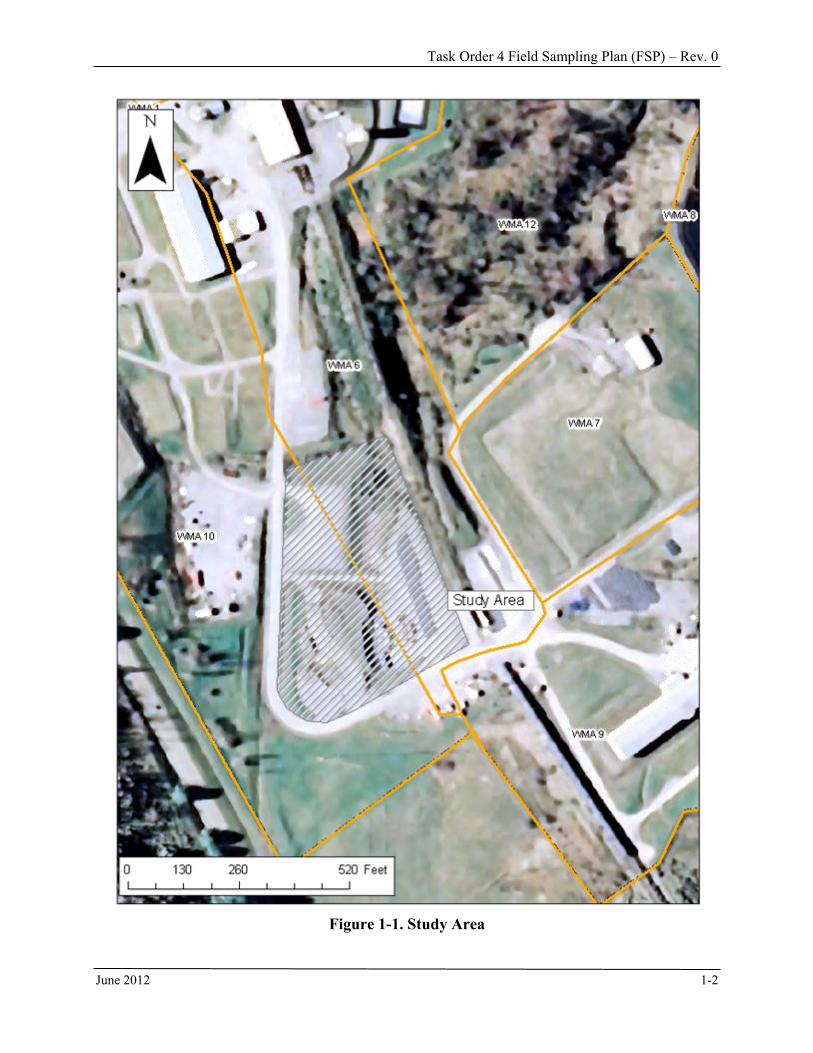
This Field Sampling Plan (FSP) has been prepared to implement the scope of work in Task Order 4. Figure 1-1 shows the study area.
Task Order 4 Field Sampling Plan (FSP) – Rev. 0
June 2012 1-2
Figure 1-1. Study Area

Task Order 4 Field Sampling Plan (FSP) – Rev. 0
June 2012 1-3
For planning purposes, the WVDP premises have been divided into Waste Management Areas (WMAs) as described in the Phase 1 DP. There are 12 WMAs, numbered 1 through 12. The HLW Canister Interim Storage Area will be constructed on the southern ends of WMAs 6 and 10. WMA 6 is approximately 14.5 acres and contains a variety of facilities, including the Rail Spur, the Above-Ground Petroleum Storage Tank, the Sewage Treatment Plant, the New Cooling Tower, the two Demineralizer Sludge Ponds, the Equalization Basin, the Equalization Tank, the South Waste Tank Farm Test Tower, the Road-Salt and Sand Shed, and the LLW Rail Packaging and Staging Area. There is an area west of the site rail spur, referred to as the vitrification hardstand, in the southern portion of WMA 6. This vitrification hardstand along with a grassy area to its north is where a portion of the HLW Canister Storage Facility will be constructed. WMA 10 is approximately 30 acres and contains support and service facilities. WMA 10 includes: (1) the Administration Building, (2) the Expanded Laboratory, (3) the New Warehouse, (4) the Security Gatehouse, (5) the Meteorological Tower, (6) the Main Parking Lot, and (7) the South Parking Lot. In addition, concrete slabs and foundations from several removed structures remain in place, along with the Former Waste Management Storage Area and various hardstands. One of these hardstands was part of the vitrification hardstand. This patch of hardstand is not contiguous with the hardstand in WMA 6. This patch of hardstand in WMA 10 is in the area where the HLW Canister Interim Storage Facility will be built. A grassy area to the south of this hardstand is also included in the area where the HLW Canister Storage Facility will be constructed. The conceptual site models for WMAs 6 and 10, presented in the CSAP, indicate little reason for the soils at the HLW Canister Storage Area to be contaminated. However, gamma exposure rate measurements ranged from 11 – 25 µR/hr at several locations where the HLW Canister Interim Storage Area will be constructed. These readings are elevated above typical natural background readings of 10 micro-R/hr or less. Also, during drilling to characterize geotechnical characteristics of the area, fill material was found from 4.5 feet (ft) to 11 ft throughout the area.5 It is possible that this material could be contaminated, although field screening measurements for gamma radiation collected during the geotechnical investigation did not detect radioactivity above natural background levels. 1.3 Objective The objective of this FSP is to evaluate the contamination status of surface and subsurface soils at the HLW Canister Interim Storage Area. The characterization survey will be performed in accordance with the specifications for Task Order 4. The specifications of Task Order 4 deviate somewhat from the characterization approach contained in the CSAP. This is because the study area has a low potential for contamination such that it could be represented as a Multi-Agency Radiation Survey and Site Investigation Manual (MARSSIM)6 Class 3 Area. Class 3 Areas are any impacted areas that are not expected to contain any residual radioactivity, or are expected to contain levels of residual radioactivity at a small fraction of the Derived Concentration Guideline Level (DCGL)w, based on site operating history and previous radiation surveys.6
Task Order 4 Field Sampling Plan (FSP) – Rev. 0
June 2012 1-4
An ultimate goal at WVDP is to meet FSSP requirements for release of the site. This end goal was used to structure the data collection specified in this FSP. Data collected under this FSP will be used to determine the presence or absence of soil contamination within the designated areas at the HLW Canister Interim Storage Area and grow a data set that directly supports the FSSP, thereby minimizing additional sample collection. The characterization survey specified in Task Order 4 includes a gamma walk-over survey (GWS) and the collection of systematic and biased surface and subsurface soil samples. The systematic and biased soil samples will be analyzed for the 18 radionuclides of interest (ROIs) and the 12 potential radionuclides of interest (PROIs) as described in the CSAP and listed in Tables 1 and 2. The GWS, which collects data for surface soils, is sensitive enough to detect the cleanup goal (CG) – Elevated Measurement Concentration (CGemc) established in the FSSP for 1 square meter (m2) areas for all gamma-emitting radionuclides. The GWS is sensitive enough to detect the CGemc for 100 m2 areas for most gamma-emitting radionuclides. Those that cannot be detected at the CGemc for 100 m2 areas, such as I-129, are likely to be comingled with those that can be detected such that they will likely be detected by the GWS and subsequent biased soil sampling. Systematic soil samples will be used to detect I-129 or other radionuclides that cannot be detected by the GWS when not collocated with gamma-emitting radionuclides having energies and abundances that allow detection using the GWS. If the results of the biased and systematic soil sampling show reason to suspect radionuclides that have no or a weak gamma radiation signal then the systematic soil sampling grid size will have to be reduced consistent with MARSSIM guidance and in consultation with the DOE Project Manager. The CGemc refers to radionuclide-specific activity concentrations that must be met over areas smaller than individual survey units as defined in the FSSP. The CGw refers to radionuclide-specific activity concentrations that must be met, on average, for each individual survey unit. The objective of the GWS is to determine if localized areas exceed the CGemc (either for 1 m2 or 100 m2) and to provide an indicator of whether the area exceeds the CGw by comparing detector response to background. Even though the GWS data is not necessarily sensitive enough to detect the CGw for all gamma-emitting ROI or PROI, the technique, when compared to the local gamma background, will provide an indicator of whether the CGw is met. This will be done by plotting the data and visually examining it for anomalies and or by constructing normal probability plots as discussed further in Section 4.3.3. The objective of systematic soil sampling is to assess the average concentration of ROI and PROI in the area for comparison to the CGw. If systematic samples indicate that the CGw is exceeded, the samples will be used to assess worker safety during the construction of the HLW Canister Interim Storage Area and to determine storage or disposal options for any soil that is excavated during storage area construction. Systematic samples are also needed to determine the concentration of ROI and PROI that do not emit gamma radiation and thus cannot be measured by the GWS. Systematic samples evaluated in conjunction with the GWS also provide an indication of the areal extent of contamination, if any. The objective of biased soil sampling for this effort is to validate the GWS indication that the CGemc was exceeded. Biased samples used in conjunction with the GWS can help determine the

Task Order 4 Field Sampling Plan (FSP) – Rev. 0
June 2012 1-5
areal extent of the contamination, assess worker safety hazards during storage area construction, and determine storage or disposal options for any soil that is excavated during construction. 1.4 Scope This is a characterization survey. The primary objective is to verify contamination status of soils to be affected by Phase 1 construction needs.4 SEC will plan and implement the characterization activities consistent with the requirements in Task Order 4 and MARSSIM guidance.6 In addition to the primary object, other objectives are to: Determine which, if any, of the ROI and PROI are present in the area and provide an
indication of whether they exceed the CG. Assess the average and maximum concentrations of ROI and PROI to assess radiation
exposures of the workers constructing the HLW Canister Storage Area. Determine if soil in the area requires excavation and storage or disposal before constructing
the canister storage pad. Determine the extent of surface and subsurface soil contamination. Evaluate appropriateness of the current list of ROIs and PROI. Verify absence of additional ROIs. Evaluate the performance of different types of detectors used during GWS. Specific work scope to be performed for this Task Order includes: 1) Clearing and grubbing, if necessary 2) Gross gamma walkover survey 3) Collection of systematic and biased soil samples from:
a. Exposed surface soil area b. Hardstand areas c. Drainage features
4) Civil survey 5) Optional work (core sampling of Hardstand areas) SEC will mobilize the appropriate equipment and qualified personnel to perform the required data collection activities associated with the task. This FSP discusses gamma walkover survey methods, civil surveying, field instrumentation, soil sampling methods, sample chain of custody documentation, quality assurance (QA)/quality control (QC) procedures, laboratory analytical methods, and statistical data evaluation methods. 1.5 Radionuclides of Interest and Cleanup Goals The focus of the characterization activities will be on radionuclides. Evaluation of chemical contamination is outside the scope of the CSAP which is the basis for this FSP.4 The list of ROI and PROI is extensive (18 and 12 respectively) and includes “hard to detect” radionuclides (i.e., non-gamma emitting easily detected by surface scans). To streamline the characterization effort, SEC will focus on Cs-137, a mixed fission product of relatively high yield and routinely found on sites impacted with mixed fission products. Cs-137 is easily detected in soil in the field due to
Task Order 4 Field Sampling Plan (FSP) – Rev. 0
June 2012 1-6
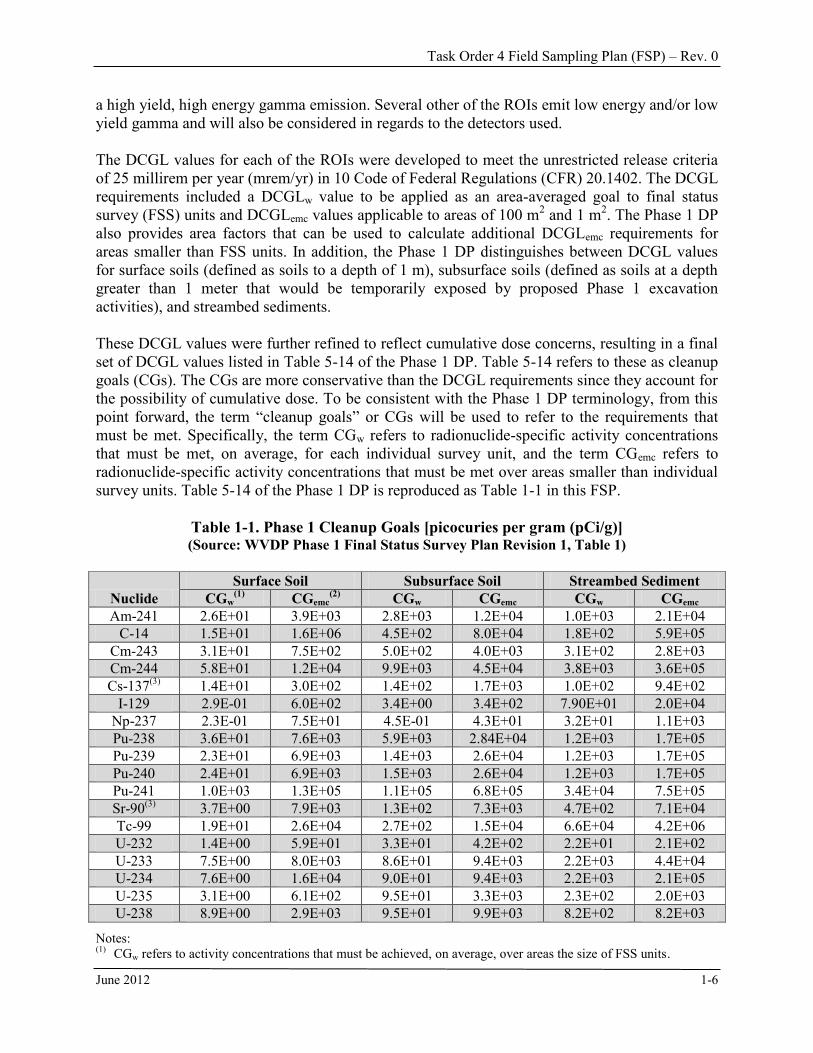
a high yield, high energy gamma emission. Several other of the ROIs emit low energy and/or low yield gamma and will also be considered in regards to the detectors used. The DCGL values for each of the ROIs were developed to meet the unrestricted release criteria of 25 millirem per year (mrem/yr) in 10 Code of Federal Regulations (CFR) 20.1402. The DCGL requirements included a DCGLw value to be applied as an area-averaged goal to final status survey (FSS) units and DCGLemc values applicable to areas of 100 m2 and 1 m2. The Phase 1 DP also provides area factors that can be used to calculate additional DCGLemc requirements for areas smaller than FSS units. In addition, the Phase 1 DP distinguishes between DCGL values for surface soils (defined as soils to a depth of 1 m), subsurface soils (defined as soils at a depth greater than 1 meter that would be temporarily exposed by proposed Phase 1 excavation activities), and streambed sediments. These DCGL values were further refined to reflect cumulative dose concerns, resulting in a final set of DCGL values listed in Table 5-14 of the Phase 1 DP. Table 5-14 refers to these as cleanup goals (CGs). The CGs are more conservative than the DCGL requirements since they account for the possibility of cumulative dose. To be consistent with the Phase 1 DP terminology, from this point forward, the term “cleanup goals” or CGs will be used to refer to the requirements that must be met. Specifically, the term CGw refers to radionuclide-specific activity concentrations that must be met, on average, for each individual survey unit, and the term CGemc refers to radionuclide-specific activity concentrations that must be met over areas smaller than individual survey units. Table 5-14 of the Phase 1 DP is reproduced as Table 1-1 in this FSP.
Table 1-1. Phase 1 Cleanup Goals [picocuries per gram (pCi/g)] (Source: WVDP Phase 1 Final Status Survey Plan Revision 1, Table 1)
Nuclide Surface Soil Subsurface Soil Streambed Sediment
CGw(1) CGemc
(2) CGw CGemc CGw CGemc
Am-241 2.6E+01 3.9E+03 2.8E+03 1.2E+04 1.0E+03 2.1E+04 C-14 1.5E+01 1.6E+06 4.5E+02 8.0E+04 1.8E+02 5.9E+05
Cm-243 3.1E+01 7.5E+02 5.0E+02 4.0E+03 3.1E+02 2.8E+03 Cm-244 5.8E+01 1.2E+04 9.9E+03 4.5E+04 3.8E+03 3.6E+05 Cs-137(3) 1.4E+01 3.0E+02 1.4E+02 1.7E+03 1.0E+02 9.4E+02
I-129 2.9E-01 6.0E+02 3.4E+00 3.4E+02 7.90E+01 2.0E+04 Np-237 2.3E-01 7.5E+01 4.5E-01 4.3E+01 3.2E+01 1.1E+03 Pu-238 3.6E+01 7.6E+03 5.9E+03 2.84E+04 1.2E+03 1.7E+05 Pu-239 2.3E+01 6.9E+03 1.4E+03 2.6E+04 1.2E+03 1.7E+05 Pu-240 2.4E+01 6.9E+03 1.5E+03 2.6E+04 1.2E+03 1.7E+05 Pu-241 1.0E+03 1.3E+05 1.1E+05 6.8E+05 3.4E+04 7.5E+05 Sr-90(3) 3.7E+00 7.9E+03 1.3E+02 7.3E+03 4.7E+02 7.1E+04 Tc-99 1.9E+01 2.6E+04 2.7E+02 1.5E+04 6.6E+04 4.2E+06 U-232 1.4E+00 5.9E+01 3.3E+01 4.2E+02 2.2E+01 2.1E+02 U-233 7.5E+00 8.0E+03 8.6E+01 9.4E+03 2.2E+03 4.4E+04 U-234 7.6E+00 1.6E+04 9.0E+01 9.4E+03 2.2E+03 2.1E+05 U-235 3.1E+00 6.1E+02 9.5E+01 3.3E+03 2.3E+02 2.0E+03 U-238 8.9E+00 2.9E+03 9.5E+01 9.9E+03 8.2E+02 8.2E+03
Notes: (1) CGw refers to activity concentrations that must be achieved, on average, over areas the size of FSS units.

Task Order 4 Field Sampling Plan (FSP) – Rev. 0
June 2012 1-7
(2) CGemc refers to activity concentrations that must be achieved, on average, over 1-m2 areas. (3) CG requirements provided for this table for Cs-137 and Sr-90 assume one half-life of decay will occur before the
possible release of the site in 2041. As part of the FSS process, these values will be decay-corrected reflecting the date of the data collection to ensure that the desired dose standard is achieved.
In addition to the 18 ROIs contained in the Phase 1 DP, another 12 radionuclides have been identified as potentially being of interest; these 12 PROIs are listed in Table 1-2. The identification process relied on historical process knowledge; to date none of these 12 has been observed in historical samples at levels that would be of dose concern and the belief is that it is unlikely that any of these 12 exist at significant levels in environmental media.3 Several of the 12 have short half-lives relative to the history of WVDP/Nuclear Fuel Services, Inc. (NFS) activities; others would have had very low abundance within the spent fuel that would have been processed at the site, compared to Cs-137 and Sr-90. FSP data collection will provide supporting data to determine whether any of these 12 radionuclides should be of interest.
Table 1-2. Twelve Radionuclides of Potential Interest (Source: WVDP Phase 1 Characterization Sampling and Analysis Plan, Revision 1, Table 3)
Radionuclide Naturally Occurring Typical Soil
Background Activity Concentrations (pCi/g)
Required Laboratory
Sensitivity (pCi/g) Yes / No Half Life (years)
Ac-227 Yes 21.8 ~ 0.05 0.1 Co-60 No 5.3 Not applicable _
Cd-113m No 14.1 Not applicable _ Eu-154 No 8.6 Not applicable _
H-3 Yes 12.3 Negligible quantities _ Pa-231 Yes 32,760 ~ 0.05 0.1 Ra-226 Yes 1,602 ~ 1 0.1 Ra-228 Yes 5.8 ~ 1 0.1 Sb-125 No 2.8 Not applicable _ Sn-126 No 12.4 Not applicable _ Th-229 No 7,340 Not applicable _ Th-232 Yes 1.4E10 ~ 1 0.1

Task Order 4 Field Sampling Plan (FSP) – Rev. 0
June 2012 2-1
2.0 ENVIRONMENT, SAFETY, HEALTH, QUALITY, AND RADIATION PROTECTION
Work for this FSP will be performed according to the SEC Environment, Safety, Health, Quality and Radiation Protection Programs (RPPs) along with supporting procedures and subordinate plans. These documents have been prepared by SEC and approved by DOE. These approved documents are implementing mechanisms of the SEC Integrated Safety Management System, SEC-ISMS, and include the following: Worker Safety and Health Program (SEC-WSHP) Radiation Protection Program (SEC-RPP) Quality Assurance Program (SEC-QAP) Environmental Protection Program (SEC-EPP) Waste Management Plan (SEC-WMP) Emergency Preparedness Plan (SEC-EmPP) Conduct of Operations Program (SEC-COP) Contractor Assurance Program (SEC-CAP) Corporate Operating Experience Program (SEC-COEP) Integrated Security Plan (SEC-ISP)


Task Order 4 Field Sampling Plan (FSP) – Rev. 0
June 2012 3-1
3.0 ROLES AND RESPONSIBILITIES This section identifies the roles and responsibilities of project personnel. 3.1 Key Project Personnel Project personnel key to performing this FSP are the Project Manager (PM), Environmental Safety and Health (ES&H) Manager, Radiological Engineer, Site Geologist/QC Coordinator, and Subcontractor Field Lead for performing Geoprobe® sampling. These individuals, at a minimum, will be at the site when soil sampling field work is performed. When only GWS data is collected, only the PM or Radiological Engineer and the ES&H Manager must be at the site. 3.1.1 SEC Project Manager The PM performs the following functions and has the following responsibilities: Serves as the primary point of contact with DOE; Ensures coordination of management, safety and health, radiation control (RADCON), and
QA functions; Manages the Direct-Push drilling subcontractor; Allocates resources to the project to ensure successful execution and completion of
milestones; Demonstrates commitment and implementation of Integrated Safety Management System
(ISMS) and Quality Assurance Plan (QAP); Coordinates with the Radiological Engineer and Site Geologist/QC Coordinator to ensure
work is performed with appropriate level of quality and in accordance with specifications and requirements;
Maintains signature authority to commit SEC; and Ensures all work and project activities are executed in accordance with established regulatory
requirements and SEC programs, plans, and procedures. 3.1.2 Radiological Engineer The radiological engineer performs the following functions: Manages the collection of field data; Maintains field logbooks; Produces tables and figures of GWS and sample data; Provides daily updates to the SEC PM; and Acts for the Radiological Protection Manager when not at the site to implement the SEC
RPP, maintain exposure records, and keep field activities as low as reasonably achievable (ALARA).
3.1.3 SEC Environmental Safety and Health (ES&H) Manager The ES&H Manager:
Task Order 4 Field Sampling Plan (FSP) – Rev. 0
June 2012 3-2
Recognizes, evaluates, recommends, and implements policies and procedures to assure awareness of and compliance with ES&H requirements of the organization;
Monitors and prevents adverse exposure to chemical, biological, and physical hazards throughout the work sites;
Directs audits of the ES&H programs to identify and correct program deficiencies, and will keep fully informed on all existing and proposed changes in occupational health and safety regulations;
Provides basic ES&H training to employees and promotes communication programs to enhance and encourage employee awareness of accident prevention, industrial hygiene, and environmental compliance; and
Ensures all work and project activities are executed in accordance with established regulatory requirements and SEC programs, plans, and procedures.
3.1.4 Site Geologist/QC Coordinator The Site Geologist/QC Coordinator: Supports soil collection activities, Performs lithological logging of soil cores, Prepares and packages soil samples, Completes sample chain of custody and ships samples for laboratory analysis, and Maintains appropriate documentation for field activities. 3.1.5 Subcontractor Field Lead The Subcontractor Field Lead: Directs the operation of the Direct Push drilling rig, Obtains the soil cores, and Decontaminates the sampling probe in between sampling locations.

Task Order 4 Field Sampling Plan (FSP) – Rev. 0
June 2012 4-1
4.0 FIELD ACTIVITIES Three survey units were identified for this characterization based on differences in physical characteristics. The three units are: Areas with exposed surface soil, Hardstands, and Drainage features. A number of field activities will be conducted as part of this effort. The principle activities include: Clearing and grubbing, if necessary; Gamma walkover survey; Systematic surface and subsurface soil sampling; Biased surface and subsurface soil sampling; and Civil surveying. 4.1 Clearing and Grubbing The HLW Canister Interim Storage Area consists of approximately 4.8 acres, 3 of which are covered with gravel (referred to as hardstands) and 1.8 acres are open land. The open land area is mowed and during a reconnaissance trip in February it did not appear that clearing and grubbing would be needed. If this is not the case when SEC mobilizes to perform the characterization, SEC will conduct clearing and grubbing activities to ensure all areas are accessible by equipment and personnel. This may include the removal of small trees, brush, grasses, etc. 4.2 Gamma Walkover Survey (GWS) SEC will perform a gross GWS of 100% accessible surfaces of the HLW Canister Interim Storage Area (the area) with one or more large volume sodium iodide (NaI) detector(s) (i.e., 2x2 inch or 3x3 inch) and a field instrument for detection of low-energy radiation (FIDLER) detector. SEC will use the Large Area Global Positioning System Survey System (LAGSS) consisting of a Trimble Global Positioning System (GPS) unit coupled to a NaI detector and to a FIDLER detector to survey the area and subsequently download and plot the results to provide a visual map and the relative gross gamma activity. The SEC LAGSS system delivers multiple gross gamma results and coordinates per square meter of surface area. The raw data will be processed into graphic depictions of gamma ray count contours to aid in the selection of biased sample locations. The data will also be used to compare the relative sensitivity of the NaI and FIDLER detectors to the mix of radionuclides present. This is a characterization survey, thus requirements for FSSs specified in the FSSP are not applicable. However, guidance in MARSSIM was used to help determine the appropriate number of samples to collect and the GWS survey areal coverage required. The entire 4.8 acre area (19,440 m2) will be surveyed using some of the guidance for a MARSSIM Class 3 FSS unit based on the low probability for radioactive material impacts in the area. The minimum MARSSIM requirements for a Class 3 survey unit survey are 10% coverage surface scan. Since 100% of the surface will be scanned, the scan requirement will exceed the MARSSIM guidance.
Task Order 4 Field Sampling Plan (FSP) – Rev. 0
June 2012 4-2
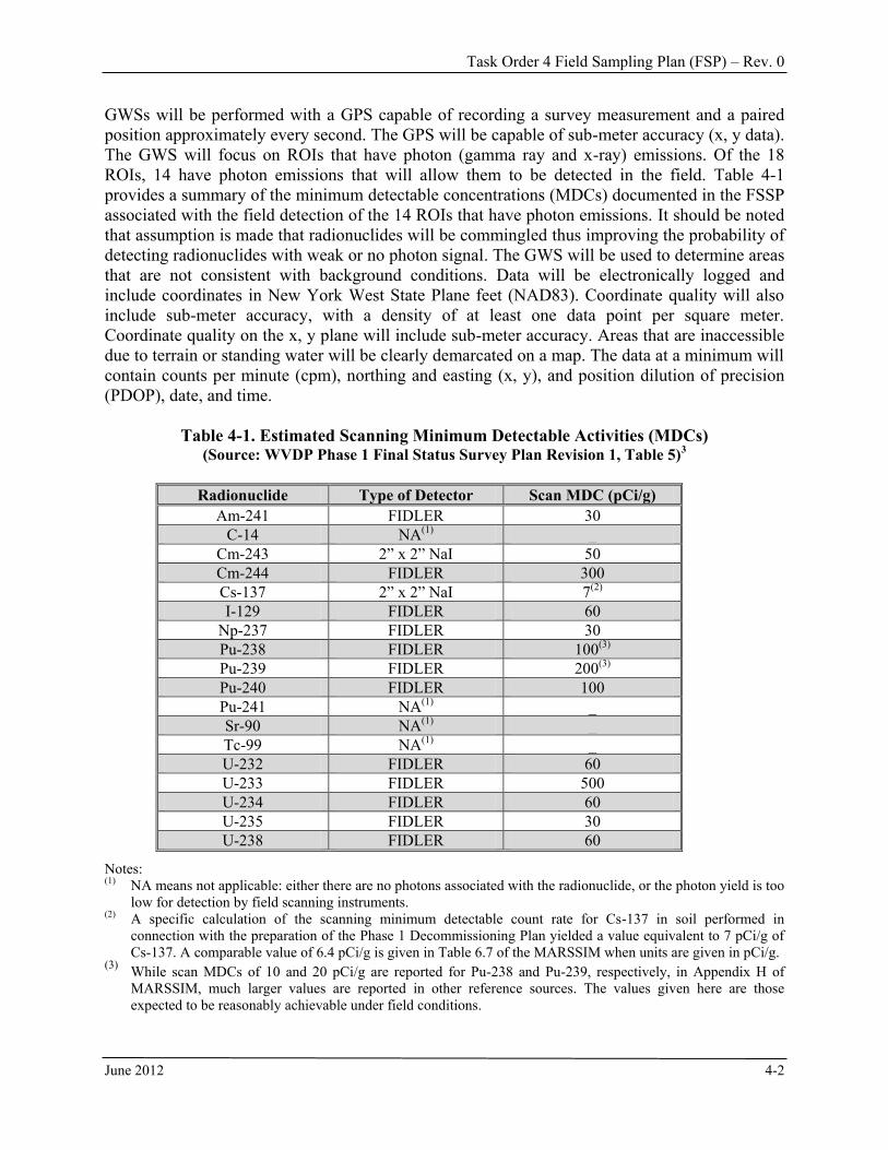
GWSs will be performed with a GPS capable of recording a survey measurement and a paired position approximately every second. The GPS will be capable of sub-meter accuracy (x, y data). The GWS will focus on ROIs that have photon (gamma ray and x-ray) emissions. Of the 18 ROIs, 14 have photon emissions that will allow them to be detected in the field. Table 4-1 provides a summary of the minimum detectable concentrations (MDCs) documented in the FSSP associated with the field detection of the 14 ROIs that have photon emissions. It should be noted that assumption is made that radionuclides will be commingled thus improving the probability of detecting radionuclides with weak or no photon signal. The GWS will be used to determine areas that are not consistent with background conditions. Data will be electronically logged and include coordinates in New York West State Plane feet (NAD83). Coordinate quality will also include sub-meter accuracy, with a density of at least one data point per square meter. Coordinate quality on the x, y plane will include sub-meter accuracy. Areas that are inaccessible due to terrain or standing water will be clearly demarcated on a map. The data at a minimum will contain counts per minute (cpm), northing and easting (x, y), and position dilution of precision (PDOP), date, and time.
Table 4-1. Estimated Scanning Minimum Detectable Activities (MDCs) (Source: WVDP Phase 1 Final Status Survey Plan Revision 1, Table 5)3
Radionuclide Type of Detector Scan MDC (pCi/g)
Am-241 FIDLER 30 C-14 NA(1) _
Cm-243 2” x 2” NaI 50 Cm-244 FIDLER 300 Cs-137 2” x 2” NaI 7(2) I-129 FIDLER 60
Np-237 FIDLER 30 Pu-238 FIDLER 100(3)
Pu-239 FIDLER 200(3)
Pu-240 FIDLER 100 Pu-241 NA(1) _ Sr-90 NA(1) _ Tc-99 NA(1) _ U-232 FIDLER 60 U-233 FIDLER 500 U-234 FIDLER 60 U-235 FIDLER 30 U-238 FIDLER 60
Notes: (1) NA means not applicable: either there are no photons associated with the radionuclide, or the photon yield is too
low for detection by field scanning instruments. (2) A specific calculation of the scanning minimum detectable count rate for Cs-137 in soil performed in
connection with the preparation of the Phase 1 Decommissioning Plan yielded a value equivalent to 7 pCi/g of Cs-137. A comparable value of 6.4 pCi/g is given in Table 6.7 of the MARSSIM when units are given in pCi/g.
(3) While scan MDCs of 10 and 20 pCi/g are reported for Pu-238 and Pu-239, respectively, in Appendix H of MARSSIM, much larger values are reported in other reference sources. The values given here are those expected to be reasonably achievable under field conditions.
Task Order 4 Field Sampling Plan (FSP) – Rev. 0
June 2012 4-3
GWSs will be performed in accordance with the GWS procedure attached in Appendix A. In general, GWSs will be performed by a technician traversing areas on foot at a rate approximately 0.5 meters per second carrying a backpack mounted GPS and the detectors. In some instances, either where terrain allows or where shielded detectors are required, a cart mounted FIDLER/ GPS setup may be deployed. The cart will be pushed by the technician or pulled by a vehicle at the same scan rate. The data will have a minimum density of 1 data point per square meter. If multiple detectors are deployed in a survey, a 100 m2 area will be surveyed by all instruments with the data logged by coordinate location and stored electronically. Multiple detectors may be deployed as a means of surveying site areas more quickly or resolving elevated gamma radiation signal from nearby buildings, waste containers, or waste storage areas, referred to as “shine.” When multiple detectors are used to address localized elevated background, at least one detector will be completely unshielded and one or more detectors will be collimated with lead in an attempt to resolve the signal from the ground surface and elevated localized background signal. To evaluate detector performance, data collection activities specified in Section 6.11.1 of the CSAP will be performed. This will include a reference area with a portion (100 m2) used for detector evaluation (see Sections 5.0 and 6.2 for more details). Each gross gamma activity detector will be evaluated by surveying and logging the data for this area. Key parameters will include average response of the detector and the variability in data results observed. Data density will be at least one reading per square meter; data will be collected in a manner that results in relatively uniform coverage for the area. In addition, static counts will be made with each detector type prior to collecting soil samples and the data will be used to evaluate the minimum detectable concentration (MDC) of each detector type. 4.3 Sample Collection Surface and subsurface soil samples will be collected during the field effort. Surface soil samples will be collected using hand trowels, shovels, or hand augers, while subsurface soil samples will be collected using direct-push drilling methods for sample collection deeper than 15 cm. Hand augers shall be used in cases where there are concerns over buried utilities or infrastructure. Details regarding use of direct-push drilling methodology are provided in Section 4.3.1. A sufficient volume of soil will be collected to allow all 18 ROIs and the 12 PROIs to be analyzed. Sufficient volume is approximately 900 g (see Table 6-2 where the sum of the minimum volumes equals 825 g) due to the extensive list of ROIs and PROIs to be analyzed. By collecting surface soil samples from 10 cm (approximately 4 inches) diameter holes 15 cm deep, and subsurface soil sample (either 85 cm or 100 cm) from 5-cm (2-inch) diameter hole, a sufficient volume of media will be collected for the required analyses. Soil samples of 15 cm depth from ground surface will be collected with either hand trowels, shovels, or a hand auger. Hand auguring through the initial 15 cm provides a safety measure to avoid contacting any underground utilities that may not have been identified prior to the commencement of fieldwork. The auger will bore a hole a minimum of 10-cm in diameter to assure sufficient amount of soil is collected. When hardstand or asphalt makes it difficult to use the hand auger, the drilling subcontractor will first break through the hardstand or asphalt, and then a hand auger will be used.

Task Order 4 Field Sampling Plan (FSP) – Rev. 0
June 2012 4-4
Hand-auger samples will be placed onto plastic sheeting and placed in stainless steel mixing bowls to be homogenized and packaged as samples. Samples collected by direct push methods will be collected in acetate liners. Once removed from the steel collection tube, the acetate liner will be cut open and the sample extracted and placed into a mixing bowl for homogenization and collection. Samples will be collected, handled, and packaged according the procedure shown in Appendix C. Surface and subsurface samples will be scanned for gamma radiation before they are homogenized. This will help determine if there are discrete horizons of radioactive contamination in the soil cores. Field notes for biased and systematic samples will include a 30-second static FIDLER count and 30-second NaI detector counts at a distance of 15 cm above the ground surface prior to acquiring the sample. A physical description of the material sampled, date, and time shall be included. Additionally, the location (coordinates) of the sample will be recorded in NY State Plane West NAD83 with a quality of ± a hundredth of a foot (± 0.01 ft) for each sample. Static readings will be recorded in a fashion that allows them to be paired with the analytical results associated with the sampled location. These paired results will be preserved and reviewed according to the specifications in Section 6.11.1 of the CSAP as work progresses. Data meeting the CSAP specifications [i.e., near or above CGw requirements for Cs-137 in an area likely affected primarily by Cs-137 impacts, an absence of any shine concerns, no surface cover, relative constant gross activity readings over a small area (2 to 3 m2), and an area that will unlikely be immediately affected by Phase 1 remediation activities] will be used to allow monitoring of FIDLER performance and determination of field MDC values for the FIDLER and NaI detectors by performing regression analyses. 4.3.1 Direct-push Drilling for Sample Collection Because of the depth of the average sample terminating at 2 meter and deeper in hardstand areas, a direct push Geoprobe® or equivalent drilling system will be utilized for collecting subsurface soil samples from 15 cm below ground surface (bgs) to 1 meter and for samples collected 1 to 2 meters bgs and deeper. This is discussed further in the subsections below. The Geoprobe® subcontractor’s procedure is shown as Appendix B. A direct push drilling system uses a hydraulic or pneumatic pressure to push a sample tube to a required depth. Specific intervals are then sampled as the sample tooling is advanced to depth. The Macro-Core Sampler is driven one sampling interval (i.e., 15 cm to 1 m) into the subsurface and retrieved using the direct push machine. Sampling tubes come in different lengths, including 4 ft and 8 ft. The soil is collected inside a solid acetate liner placed inside the metal sampling tube. Once retrieved and the metal sampling tube split open, the acetate liner is removed and cut open, exposing the soil from the required sample interval. The soil is then extracted, homogenized, and packaged. The direct push core diameter will be a minimum of 5 cm as stated above. Samples will be collected, handled, and packaged in accordance with the procedure shown in Appendix C.
Task Order 4 Field Sampling Plan (FSP) – Rev. 0
June 2012 4-5
Open-tube samplers will be used for stable soils. In the open-tube configuration, coring starts at the ground surface with a sampler that is open at the leading end. The sampler is driven into the subsurface and then pulled from the ground to retrieve the sample. In unstable soils which tend to collapse into the core hole, the sampler will be equipped with a center rod closed-point assembly. The point fits firmly into the cutting shoe and is held in place by the center rod. This prevents collapsed soil from entering the sampler as it is advanced to the bottom of an existing hole, thus ensuring collection of a representative sample. When a closed point sampler is needed, the soil sampler is secured with a vinyl end cap. Loose soils are prevented from falling from the bottom of the sampler as it is retrieved from depth. A core catcher on the bottom of the sample tube prevents loss of unconsolidated material. Soil samples are removed by unthreading the cutting shoe and pulling out the liner. A few sharp taps on the cutting shoe with a pipe wrench will often loosen the threads to allow hand removal. If needed, the interior of the cutting shoe has wrench flats for attaching a wrench and loosening tight threads. When the cutting shoe is removed, the liner may be removed. Undisturbed samples are collected by cutting the liner. Holes from which samples were removed will be filled with bentonite chips. This will prevent generation of dust which could create an inhalation hazard. The chips fill in the holes and then expand when contacted by water, thus completely sealing the holes. 4.3.2 Systematic Soil Sampling The number of samples required (N) per survey unit was evaluated using the detection of Cs-137 at the CGw 14 pCi/g. The Lower Bound of the Gray Region (LBGR) was set at ½ the Cs-137 CGw.6 The standard deviation was assumed to be 30 percent of the LBGR6 or 2.1 pCi/g. This provides a relative shift greater than 3. The probability of Type I and Type II errors were set to 0.1. These error probabilities were considered acceptable because an objective of this survey is to characterize, not release the area for unrestricted use. The number of samples per survey unit was nine, using these parameters. Given that the surface area of the area with exposed surface soils was less than 8,000 m2, it was determined that only eight samples would be sufficient; one per each 1,000 m2. The determination that one sample location per 1,000 m2 was determined jointly between DOE and SEC as a means of keeping analytical costs low while keeping in mind the sample number calculation using MARSSIM guidance. Because this is a characterization survey, the samples will be collected systematically rather than randomly as indicated in MARSSIM for Class 3 Areas. The approximately evenly spaced systematic samples will be better suited than random samples to evaluate the areal extent of contamination, if any is found. The systematic samples will have a random start point to help provide a representation of average ROI and PROI concentrations, if found. Systematic samples will also document contamination levels of radionuclides that cannot be detected by the GWS. The samples will be located such that each sample represents approximately 1,000 m2, and will be moved within the 1,000 m2 area at the discretion of the SEC PM to locations more likely to potentially be contaminated, for example in a topographical depression.2
Task Order 4 Field Sampling Plan (FSP) – Rev. 0
June 2012 4-6
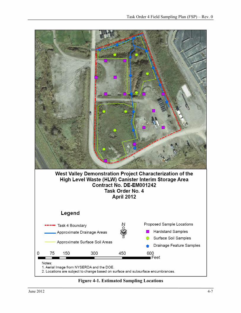
To characterize the soils within the HLW Canister Interim Storage Area, systematic surface and subsurface soil samples will be collected from three survey units within the HLW Canister Interim Storage Area. The estimated locations for the sampling are shown in Figure 4-1. 1) Exposed Surface Soil Area − SEC will collect eight core samples (approximating the
MARSSIM survey unit minimum) within the 7,300 m2 (1.8 acre) open land area, each representing no more than 1,000 m2. Sample locations will be systematically located on an equal-distant triangular grid with a random start point within the area. Sample locations may be moved to likely locations for contamination as discussed above. Each core sample will be scanned for gamma radiation with results recorded and then divided into two parts: 0 – 15 cm and the 15 – 100 cm. The cores will be sent to the laboratory and analyzed for the 18 ROIs and 12 PROI. The interval sampled for analysis shall be soils and not hardstand or fill. One QC field duplicate 2-meter core will also be collected. Therefore, nine 0-15 cm samples and nine 15-100 cm samples will be analyzed. A 1 − 2 m segment will also be cored at the same time as the first two intervals. This sample will be labeled and subsequently archived. If a 15 – 100 cm sample indicates radionuclide contamination impacts above the surface soil CG, then the sample will be sent to the laboratory and analyzed for the ROI and PROI. One field duplicate QC core sample will also be collected as part of the systematic sampling.
2) Hardstand Areas − SEC field personnel will collect 13 samples within the 12,100-m2 (3-acre)
hardstand areas, each representing no more than 1,000 m2. If the GWS results identify
portions of hardstands that are of potential contamination concern, these areas would be selected for subsurface sampling. In areas where GWS anomalies are not identified, sample locations will be randomly selected. From each location selected for sampling, Geoprobe® soil core retrieval will be conducted through the hardstand material into the underlying soil. Hardstand areas may have been backfilled with soils prior to the placement of compacted gravel. The Geoprobe® core will extend at least 1 meter into the original soil surface. The thickness of the compacted gravel, the thickness of fill soil if present, and the depth to the original soil surface, if identifiable, will be reported. At minimum, a 1-meter long core of soil underlying the hardstand material will be retrieved. Down hole scans will be conducted (and/or an equivalent methodology used such as core scans if down hole scans are infeasible) to determine if there are subsurface soil intervals exhibiting elevated readings. The subsurface scans will be logged and made available for DOE review. SEC may be required to bias sample a subsurface interval for the analysis of the 18 ROIs and the 12 PROIs if elevated readings are detected. At each soil core location, at least two samples will be collected from soils beneath the hardstand material. The first will represent the first 0 – 15 cm soil interval encountered, and the second will represent the subsequent 15 – 100 cm soil interval. In both cases, sufficient soil mass will be obtained to allow for the analysis of the 18 ROIs and the 12 PROIs.
3) Drainage Features − There are three drainage features of interest in the 4.8 acres. The first
runs west to east for a distance of approximately 80 m along the north side of the study area.
Task Order 4 Field Sampling Plan (FSP) – Rev. 0
June 2012 4-7
Figure 4-1. Estimated Sampling Locations
Task Order 4 Field Sampling Plan (FSP) – Rev. 0
June 2012 4-8
The second runs south to north through the middle of the area for a distance of approximately 180 m. The third runs south to north along the base of the railroad track embankment for a distance of approximately 120 m. Systematically-spaced sampling locations will be selected from the footprint of each feature with a spacing of 30 m; consequently, 13 sampling locations will be sampled. A random start point in each of the drainage features will be used to determine the sample locations. From each location, one sample will be collected, representing the 0 − 15 cm soil interval. Sufficient soil mass will be obtained to allow for the analysis of the 18 ROIs and the 12 PROIs. Laboratory results from the 0 – 15 cm samples will be compared to the Phase 1 surface soil CGs to determine if there are impacts are of potential dose concern. If a 0 – 15 cm sample indicates radionuclide contamination impacts above the surface soil CG, then an additional sample from that location representing the 15 – 100 cm interval will be analyzed allow for the analysis of the 18 ROIs and the 12 PROIs. This second sample will be collected and archived for the later analysis if required.
4.3.3 Biased Soil Sampling SEC may be required to bias sample one or more locations exhibiting elevated GWS results relative to the surrounding area. “Elevated GWS results” is somewhat subjective as it depends on ambient background, type of surface cover, elevation (whether in a ditch or on a rise), and shine from buildings and waste containers. Locations having a gamma signal greater than three standard deviations above local background will be considered for biased sampling. In areas where it is less obvious that there is an elevated gamma signal coming from the soil surface, a normal probability plot will be used to look for gamma signal that is not normally distributed. Background signal tends to be normally distributed. The normal probability plot is a tool used to identify where a second data population (in addition to background) exists. Such a second population would represent gamma signal from contamination plus local background signal. The number and location of these biased soil samples will be determined based on GWS results for the area in consultation with DOE. Decisions on the location of biased sample locations will be documented in the field logbook. Currently five sample locations are assumed. Biased sampling will focus on those locations that GWS data indicate are most likely to have had measurable radionuclide contamination impacts. From each location selected for sampling, two samples will be collected. The first will represent the 0 – 15 cm soil interval, and the second will represent the 15 – 100 cm soil interval. In both cases, sufficient soil mass will be obtained to potentially allow for the analysis of the 18 ROIs and the 12 PROIs. Laboratory results from the 0 – 15 cm and 15 – 100 cm soil samples will be compared to the Phase 1 surface soil CG to determine if these impacts are of potential dose concern. The 12 PROIs do not currently have surface soil CG standards. The analytical results of the 12 PROIs will be evaluated to determine if the concentrations are a potential dose concern. If a 15 – 100 cm sample indicates radionuclide contamination impacts above the surface soil CG standards, then an additional sample from that location representing a 1 – 2 m interval will be collected to
Task Order 4 Field Sampling Plan (FSP) – Rev. 0
June 2012 4-9
allow for the analysis of the 18 ROIs and the 12 PROIs. The 1 – 2 m sample interval will be collected and archived at the same time as the 0 − 15 cm and 15 – 100 cm intervals are collected to negate the need for future re-mobilization of the sampling equipment and personnel. Although not expected, GWS results may indicate portions of hardstands that are of potential contamination concern. If this occurs, DOE may, at its discretion, direct sampling hardstand material for further analysis from the location(s) of concern. In this event, sampling will focus on hardstand material to a depth of 15 cm. Sufficient hardstand material will be collected to provide sufficient mass of material passing through a 10-mesh sieve to potentially allow for the analysis of the 18 ROIs and the 12 PROIs. Such sampling will be performed with a shovel or by using drilling equipment supplied by the Geoprobe® subcontractor to break up sufficient material to form a sample. 4.4 Civil Surveying Requirements A civil surveyor licensed in New York State will be used to collect topographic survey information. A variety of instrumentation may be utilized to collect the positional data including total stations (robotic and manual), kinematic and real-time kinematic GPS, and Light Detection and Ranging (LIDAR). The appropriate technology will be selected based on the logistical parameters associated with the survey. The surveys will be used to identify excavation boundaries, structures, utilities, and sample locations, both systematic and biased samples. Measurements shall record northing, easting, and elevation, and shall be accurate to ± a hundredth of a foot (± 0.01 ft.).
4.5 Decontamination Sampling equipment used during surface/subsurface soil sampling will be free from contamination and decontaminated prior to use. Field decontamination should be done near the work area. Special precaution should be taken to contain solids and liquids that are created during the decontamination process. Equipment potentially requiring decontamination may include stainless steel scoops, spoons, bowls, core barrels, etc. Other equipment used during sampling activities that does not directly contact sample materials shall be cleaned to remove potential soil contamination. The direct push or Geoprobe® sampler will be free of dirt, mud, oil, or other contaminants before being permitted on-site. An incoming radiological survey will be performed according to procedures supporting the SEC RPP. If the machine has contamination exceeding the limits in SEC-RP-10, Contamination Control and Monitoring, it will be turned away from WVDP. The split spoon or Macro-Core samplers will be decontaminated after each sample location and before proceeding to the next location. Decontamination will also be performed on all sampling tools after each sample is collected. Since sampling is for radionuclides and not chemicals, the effectiveness of decontamination can be determined by field radiological analysis with swipes. It will be acceptable to wipe off sampling equipment with dry or damp cloths or masslin and to verify that there is no contamination detected using field radiological analyses. If contamination is detected or if dirt or debris remains after wipe-down, then soap, water, and brushes may be
Task Order 4 Field Sampling Plan (FSP) – Rev. 0
June 2012 4-10
used. Rinsing with clear water will follow the use of soap. This approach will avoid large quantities of water and cleaning supplies and will save time and effort. 4.6 Investigation Derived Waste (IDW) The field activities in this plan will generate IDW. These materials generally contain soils, water, and used personal protective equipment (PPE). When accumulated, these materials must be managed appropriately to minimize the exposure and risks to human health and the environment while adhering to applicable regulatory requirements. IDW will be managed and disposed of consistent with SEC-WMP, Waste Management Plan. The IDW includes all materials generated during project performance that cannot be effectively reused, recycled, or decontaminated in the field. It consists of materials that could potentially pose a risk to human health and the environment (e.g., sampling and decontamination wastes) and also materials that have little potential to pose risk to human health and the environment (e.g., sanitary solid wastes). Two types of IDW will be generated during the implementation of field activities: indigenous and non-indigenous. Indigenous IDW expected to be generated during FSP activities will primarily be soils or soil-like material. Non-indigenous IDW expected to be generated includes decontamination fluid/water and miscellaneous trash, and possibly some anti-contamination PPE. Radiological contamination currently is not expected at levels that will require anti-contamination PPE. When accumulated, the media will be managed appropriately to minimize exposure and risks to human health and the environment while adhering to applicable regulatory requirements. In some instances, it may be appropriate to return IDW to its original location; an example of this would be returning archived soils to the location where collected after characterization work at a particular location is complete. In other cases, returning IDW to its original location is not an option. IDW minimization is a goal. IDW generated during this FSP will be limited to used PPE, if any, and a small volume of decontamination water. This PPE will be characterized for disposal using the results of the soil samples to identify the radioactive contaminants. Shoe covers worn will have the highest potential to be contaminated. Therefore, one in 10 shoe covers will be checked for total and removable surface contamination according to procedures supporting the SEC RPP. The results of these surface contamination measurements, along with the radioactive contaminants identified in the soil samples, will be used to characterize the PPE. Sampling and drilling tools will be decontaminated. Decontamination will be performed with a steam cleaner in some cases and with a cleaning agent, water, and brushes in others. The steam will not generate any IDW. The quantity of water used will be limited to that squirted onto wipes or dipped onto brushes from a bucket or drum. This water will be allowed to evaporate as possible. If evaporation is not completely successful, the water will be drummed and sampled by dipping a sample from the drum. The sample will be analyzed for radioactivity and the drum contents will be managed and disposed of in accordance with the SEC-WMP. Archived samples that are not analyzed because there are no concerns over contamination will be returned to their place of collection and spread on the ground surface.

Task Order 4 Field Sampling Plan (FSP) – Rev. 0
June 2012 5-1
5.0 REFERENCE AREAS To date, a reference or background area has not been established for the site. However, a background reference area is needed. A background reference area, or areas if more than one is needed, will be selected and sampled as part of a separate Task Order as such work is not in the scope of Task Order 4.

Task Order 4 Field Sampling Plan (FSP) – Rev. 0
June 2012 6-1
6.0 QUALITY ASSURANCE/QUALITY CONTROL SEC will implement QA/QC measures throughout the project to ensure that all decisions are made on the basis of data of acceptable quality. Pursuant to the contractual requirements, a Program Quality Assurance Plan (QAP), SEC-QAP, has been prepared and submitted under separate cover which discusses specific requirements for quality assessments, non-conformance, the use of procedures, reporting, document control, and records management. The QAP is an “umbrella” document under which all project work is conducted and assessed. The QAP provides the framework for identifying and achieving compliance to American Society of Mechanical Engineers (ASME) National Quality Assurance (NQA) 1-2008 with the NQA-1a-2009 addenda (or a later edition), Quality Assurance Program Requirements for Nuclear Facilities Applications. SEC also implements Parts I and Sections 2.7 and 2.21 of Part II of the NQA-1 standard in a graded approach, as applicable to the activity. The QAP is implemented through SEC QA standard operating procedures (SOPs). The QAP and SOPs are designed to achieve compliance with DOE Order 414.1D, Quality Assurance, and 10 CFR Part 830.122, Quality Assurance Criteria. Compliance to requirements identified in the Program QAP is mandatory by all SEC employees and subcontractors and will ensure SEC provides a service of known quality during the performance of this contract. The SEC PM and the Field QC Representative shall be responsible for ensuring the execution of the quality requirements during the duration of Task Order 4. All workers are responsible for meeting and following quality requirements. SEC will maintain direct, concise, and daily contact/coordination with the DOE PM, or designee, concerning field operations and scheduling field activities. The primary point of contact for all communications regarding the project will be the SEC PM. The SEC PM, or designee, will participate in a weekly project meeting throughout the period of performance of the contract. Participation may be by phone when field activities are not scheduled. This section of the FSP outlines the QA/QC requirements specific to the field portion of Task Order 4, including equipment, instrumentation, sample collection methodology, and laboratory analysis and data management. QA/QC requirements specific to elements of the fieldwork are discussed in detail below and include: Instrument calibration, testing, and maintenance quality requirements Gamma walkover survey QA/QC requirements Field documentation
− Field logbooks − Photographs
Sample QA/QC − Sample collection − Sample numbering − Sample labeling − Sample packaging − Additional requirements for radiological samples − Chain of custody records − Sample shipping
Task Order 4 Field Sampling Plan (FSP) – Rev. 0
June 2012 6-2
− Laboratory receipt of sample forms − Sample documentation process − Corrections to documentation
Laboratory and data QA/QC ─ Laboratory analysis ─ Reporting
Data verification and validation − Data verification − Data validation
Data quality objectives (DQOs)/indicators − Precision − Accuracy − Representativeness − Completeness − Comparability
6.1 Radiological Instrument Calibration, Testing and Maintenance Quality
Requirements Calibration: Radiological instruments will be calibrated before first use by the manufacturer or a qualified calibration service in accordance with procedures supporting the SEC RPP. Note that calibration is not required for FIDLER and NaI detectors as they read in count rates relative to the gamma signal at the field location. Daily source checks for all instruments (including FIDLER and NaI detectors) will be performed and documented on project QC forms in accordance with the applicable RPP procedure. Additional operational checks will be conducted if an instrument is suspected of malfunction during data collection, is suspected as damaged, or critical data acquisition procedures require more frequent checks. Any piece of equipment that does not perform according to procedural requirements will be tagged out and not used until it is repaired or appropriately replaced. QC limits for radiological instrument calibration will be determined during the initial setup and tuning of each detector system in accordance with RPP procedures. New QC limits will be established after subsequent calibrations and significant repairs which may have affected detector performance. A lower control limit and an upper control limit will be determined for each FIDLER and NaI detector system at a two or three sigma tolerance level. Control charts to monitor performance of each detector system will be maintained. Calibration checks will ensure that the instruments are functioning within acceptable QC tolerances. All instrument checks will be documented and the PM or designee will review them. Field QC documentation will be retained on site in project files and will be maintained as project records. Each operational check will consist of a background and source check set at a fixed and consistent geometry. The source check involves exposing the detection system to a known radioactive sealed source (for example, 10 microcuries of Cesium-137) of specific activity for a predetermined duration (typically one minute). These sealed sources will be exempt quantities. If the QC checks fail, the operational check procedure will be repeated. After three failures, the instrument will be taken out of service until the cause of the failure is determined and corrected.
Task Order 4 Field Sampling Plan (FSP) – Rev. 0
June 2012 6-3
Upon resolution, the instrument must pass the operational checks and QC limits before returned to service. Calibration Frequency: All detection systems will be calibrated in accordance with the manufacturer’s specifications, or annually. The detector systems will be calibrated if it fails a performance check or after repairs potentially affecting its response. Calibration will be performed by either the manufacturer, qualified vendor, or the project team following the manufacturer’s calibration specification and procedures in accordance with American National Standard, Radiation Protection Instrumentation Test and Calibration, Portable Survey Instruments, N323A-1997 (IEEE 1997) and American National Standard for Calibration of Germanium Detectors for In-Situ Gamma-Ray Measurements, N42.28-2002 (IEEE 2004), if applicable. Calibration sources will be traceable to the National Institute of Standards and Technology (NIST). Testing, Inspection, and Maintenance Requirements: All instruments and equipment used will be serviced and maintained only by qualified personnel in accordance with the manufacturer's guidelines and recommendations. Routine equipment maintenance and calibration will be as specified by RPP procedures. Instruments will be operated by the project team according to RPP procedures. Each radiological instrument will receive a unique identification code to allow easy tracking of equipment and to associate data with the appropriate instrument. This tracking system allows data reviewers to identify instruments that may have malfunctioned, track trends in data which may indicate slow degradation of the detection system, and other adverse conditions affecting data quality. 6.2 Gamma Walkover Survey Quality Assurance/Quality Control Requirements The following minimum QA/QC requirements will be adhered to when implementing the gross GWSs: Daily Inspection: Each detector used on WVDP premises will undergo a documented check
source evaluation each day it is used. The purpose of daily check source evaluation is to identify any deviations in the expected detector response. The evaluations will be documented on a control chart that has been developed and maintained specifically for this purpose. The variability, as measured by the standard deviation, will be used to construct two and three standard deviation error bars for the control charts. Daily readings that are more than two standard deviations away from the mean response will require a second measurement. If the second measurement also is more than two standard deviations away from the mean response or the initial measurement was more than three standard deviations from the mean response, the detector will be evaluated for evidence of potential problems and corrective actions taken as necessary before routine use of the detector is resumed. The inspection records will be maintained onsite as project records.
Background Reference Area: Background reference area(s) will be established under another
task order and used for detector data quality evaluation purposes (see Section 5.0), as follows:
Task Order 4 Field Sampling Plan (FSP) – Rev. 0
June 2012 6-4
1. SEC will select a background reference area and obtain approval from the DOE PM. 2. The background reference area will be surveyed with each detector prior to initial use on the
WVDP premises. 3. The collected data will be logged each day. 4. A 100 m2 portion of the reference area will be covered in a manner that maintains relatively
stable soil moisture conditions (the cover will be removed prior to each survey). 5. The data from the reference area (as a whole) will be used to evaluate the range of detector
background responses. Data from the covered area will be used to compare responses across detectors. The purpose of these comparisons is to allow the development of scaling factors, as necessary, to be used to standardize gamma walkover data from different detectors. Key parameters of interest are the average activity concentration observed, the standard deviation (as a measure of background variability), and the 95 percent and 99 percent upper tolerance level (UTL) for the background concentration.
Control Point: A surface soil control point will be established and maintained through the life
of Phase 1 D&D activities. Each detector deployed on WVDP premises will have two 30-second measurements taken at the control point each day: one at the start of a day’s activities and one at the end. These data will be recorded and a control chart developed and maintained for each detector. The purpose of this activity and the control chart is to identify transient soil/meteorological conditions that may be adversely affecting detector response or trends in detector behavior that may be a concern. The variability, as measured by the standard deviation, will be used to construct two and three standard deviation error bars for the control charts. One or more daily controlled measurements would be obtained and added to the control charts. Daily readings that are more than two standard deviations away from the mean response will require a second measurement. If the second measurement also is more than two standard deviations away from the mean response or the initial measurement was more than three standard deviations from the mean response, the detector will be evaluated for evidence of potential problems and corrective actions taken as necessary before routine use of the detector is resumed.
Identification of Shine Potential: Prior to surveying an area of interest, the potential for shine
will be evaluated. Shine may be the result of proximity to a building with a history of structural contamination, or it may be a product of geometry and contamination in excavation walls (i.e., deep excavations). If shine is identified as a potential concern, the potential shine impact will be assessed through the use of shielding and/or comparing results from 15-cm height readings with 1-m height readings. If it is determined that shine impacts could be significant, a mitigating strategy will be used, such as 1) the use of a shielded detector or 2) the application of shine correction factors to acquired data.
Review of Data: Data that are collected as part of gross gamma activity surveys will be
mapped and reviewed for completeness to ensure that there are no areas that lack survey coverage. The review will also determine any data quality problems, either in coordinate information or detector response. Examples of data quality issues would be mapped data lines that deviate significantly from the known path or data points that clearly fall outside the area being surveyed. Examples of the latter are inexplicable trends in sequential readings that appear to be a function of time rather than location. Any gaps that are identified will be discussed with the DOE PM and corrected prior to demobilization.

Task Order 4 Field Sampling Plan (FSP) – Rev. 0
June 2012 6-5
6.3 Field Documentation Data collected in the field includes field logbooks, sample collection data, and location information. SEC personnel responsible for the collection of data during the field portion of Task Order 4 will adhere to the quality requirements outlined for collecting, managing, and recording data. Data will be strictly controlled and, where necessary, checked for accuracy prior to submission to the DOE PM or for use in the Final Project Report. Copies of field data will be maintained in a controlled manner for the duration of the field work. Field log books, chain of custody forms, sample log sheets, photographs, and other pertinent documentation are all considered records and will be managed according to SEC-Q17, Records Management. 6.3.1 Field Logbooks A field logbook will be maintained throughout the duration of the project. All information pertinent to field activities, including field instrument calibration data, will be recorded in field logbooks or on the forms specified by SEC RPP procedures. The logbooks will be bound and the pages consecutively numbered. Entries in the logbooks will be made in black waterproof ink and will include, at a minimum, a description of all activities, individuals involved in field activities, dates and times of sampling, weather conditions, any problems encountered, and all field measurements. Instrument calibration information, such as lot numbers, manufacturer names, and expiration dates of standards used for field calibration will also be recorded in field logbooks. Each day’s activities will be summarized in the field logbooks. Sufficient information will be recorded in the logbooks to permit reconstruction of all field activities conducted. When not being utilized during field work, all field logbooks will be kept in the possession of the Task Manager or designee in a secure place. Upon completion of the field activities, all logbooks will become part of the final project evidence file. Entries recorded in logbooks will include, but not be limited to, the following information: Author, date, and times of arrival to and departure from the work site; Purpose of the field activity and summary of daily tasks; Names and responsibilities of field crew members; Sample collection method; Number and volume of samples collected; Information regarding sampling changes, scheduling modifications, and change orders; Details of sampling locations, including a sketch map illustrating the sampling locations; Field observations; Types of field instruments used and purpose of use, including calibration methods and
results; Any field measurements made that were not recorded electronically; Sample identification number(s); and Sample documentation information.

Task Order 4 Field Sampling Plan (FSP) – Rev. 0
June 2012 6-6
6.3.2 Photographs Photographs can be an important source of supplemental information during a site investigation. Examples of when photographs are appropriate include when there is a need for visual evidence of potential contamination, evidence of obstructions that require moving sampling locations, documentation of sampling points, and documentation of anomalous conditions that might affect either data quality or data interpretation. If photographs are taken to document sampling points to facilitate relocating the point at a later date, two or more permanent reference points should be included within the photograph. In addition to the information recorded in the field logbook, one or more site photograph reference maps will be prepared as required. SEC will provide cameras to DOE personnel at any time during the field work for review and approval of photos taken. 6.4 Sample Quality Assurance/Quality Control 6.4.1 Sample Collection There are a number of soil samples that are prescribed for collection during the implementation of Task Order 4, as described in Section 4.0. In order to ensure identification and quantification of all sources of error associated with each step of a monitoring program, control samples are collected so that the resulting data will be of known quality. Soil samples will be collected by using a stainless steel trowel or sampling spoon and will be homogenized in a stainless steel bowl or container prior to containerization. Visually identifiable non-soil components such as stones, twigs, and foreign objects will be manually separated in the field and excluded from the laboratory samples to avoid biasing results low. A label shall be affixed to each sample container in accordance with Section 6.4.3 of this FSP. Sample QC will be defined with the collection and analysis of field duplicates and matrix spike (MS)/matrix spike duplicates (MSDs) according to the following methodology: Field Duplicate: The field duplicate involves collecting two separate (replicate) samples from
a single sample location, storing in separate containers, and submitting them for analysis to the laboratory as two separate samples. Samples will be given separate sample numbers and labelled so the laboratory does not know the sample is a duplicate. The field duplicate will provide information on the overall variability or precision of both the sampling technique and the analytical laboratory. One field duplicate will be collected for each of the three survey units.
MS/MSD: In order to demonstrate that the extraction or digestion equipment and methods
used in the laboratory for sample analysis does not result in contamination of the samples, an additional group of field samples will be analyzed by the laboratory at a rate of 1 per 20 of the same matrix. Normal laboratory procedures are used to analyze spikes and duplicates.
A sample log sheet (Appendix E) will also be completed for each quality sample collected in
the field.
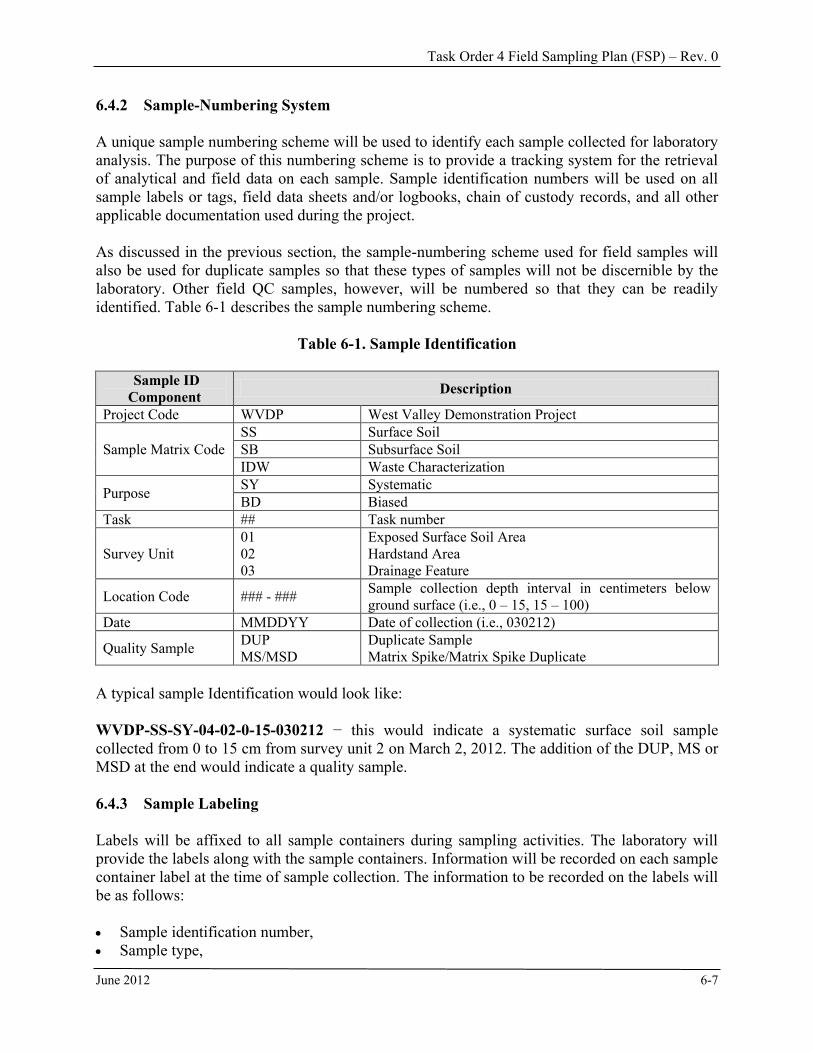
Task Order 4 Field Sampling Plan (FSP) – Rev. 0
June 2012 6-7
6.4.2 Sample-Numbering System A unique sample numbering scheme will be used to identify each sample collected for laboratory analysis. The purpose of this numbering scheme is to provide a tracking system for the retrieval of analytical and field data on each sample. Sample identification numbers will be used on all sample labels or tags, field data sheets and/or logbooks, chain of custody records, and all other applicable documentation used during the project. As discussed in the previous section, the sample-numbering scheme used for field samples will also be used for duplicate samples so that these types of samples will not be discernible by the laboratory. Other field QC samples, however, will be numbered so that they can be readily identified. Table 6-1 describes the sample numbering scheme.
Table 6-1. Sample Identification
Sample ID Component Description
Project Code WVDP West Valley Demonstration Project
Sample Matrix Code SS Surface Soil SB Subsurface Soil IDW Waste Characterization
Purpose SY Systematic BD Biased
Task ## Task number
Survey Unit 01 02 03
Exposed Surface Soil Area Hardstand Area Drainage Feature
Location Code ### - ### Sample collection depth interval in centimeters below ground surface (i.e., 0 – 15, 15 – 100)
Date MMDDYY Date of collection (i.e., 030212)
Quality Sample DUP MS/MSD
Duplicate Sample Matrix Spike/Matrix Spike Duplicate
A typical sample Identification would look like: WVDP-SS-SY-04-02-0-15-030212 − this would indicate a systematic surface soil sample collected from 0 to 15 cm from survey unit 2 on March 2, 2012. The addition of the DUP, MS or MSD at the end would indicate a quality sample. 6.4.3 Sample Labeling Labels will be affixed to all sample containers during sampling activities. The laboratory will provide the labels along with the sample containers. Information will be recorded on each sample container label at the time of sample collection. The information to be recorded on the labels will be as follows: Sample identification number, Sample type,
Task Order 4 Field Sampling Plan (FSP) – Rev. 0
June 2012 6-8
Sampled interval (e.g., 0 to 15 cm), Site name and sampling station number, Analysis to be performed, Date and time of sample collection, and Sampler’s name and initials.
Personnel collecting the samples will provide sample collection information within the field logbook (i.e. time, location, and sample ID) so that a cross-reference can be made if necessary. 6.4.4 Sample Packaging
Field samples will be placed in wide-mouth 500- or 1,000-ml nalgene containers provided by the laboratory. When samples require more than 1,000-ml, the sample may be placed in two 1,000-ml nalgene jars with both jars placed in the same zip lock plastic bag. Both jars and the bag shall bear the same sample number. Prior to use, the exterior of the containers will be checked for radioactive contamination and decontaminated if any is detected, prior to filling. The containers will be packaged in thermally insulated rigid-body coolers. Sample packaging and shipping will be conducted in accordance applicable U.S. Department of Transportation (DOT) specifications. The site geologist/QC will be responsible for packaging and shipping the samples and will verify completeness of sample shipment preparations. In addition, the laboratory will document the condition of the environmental samples upon receipt. This documentation will be accomplished by using the Cooler Receipt Checklist (SEC-FSP-F01) shown in Appendix F. The site geologist/QC specialist responsible for shipping the samples from the field to the laboratory will be responsible for completing the chain of custody form and noting the date and time of shipment. This individual will also inspect the form for completeness and accuracy. After the form has been inspected and determined to be satisfactorily completed, the responsible individual will sign, date, and note the time of transfer on the form. The chain of custody form will be sealed in a plastic bag and placed inside the cooler used for sample transport after the field copy of the form has been detached. The field copy of the form will be appropriately filed and kept at the project premises for the duration of the activities and managed as a project record. In addition to the chain of custody form, chain of custody seals will also be placed on each cooler used for sample transport. These seals will consist of a tamper-proof adhesive material placed across the lid and body of the coolers. The chain of custody seals will be used to ensure that no sample tampering occurs between the time the samples are placed into the coolers and the time the coolers are opened for analysis at the laboratory. Cooler custody seals will be signed and dated by the individual responsible for completing the chain of custody form contained within the cooler. 6.4.5 Additional Requirements for Samples Classified as Radioactive Materials
Transportation of radioactive materials is regulated by the DOT under 49 CFR 173.401. Samples generated during project activities will be transported in accordance with procedures that ensure

Task Order 4 Field Sampling Plan (FSP) – Rev. 0
June 2012 6-9
compliance with regulatory requirements. The following will be performed for radioactive materials: The cooler must have the shipper and receiver addresses affixed to it in case the courier air
bill is lost during shipping. Samples will be screened prior to packing to determine whether they meet the definition of a
DOT class 7 (radioactive) material. For samples that meet DOT requirements for radioactive materials:
− The cooler will be surveyed for radiation and to ensure the package meets the requirements for limited quantity as found in 49 CFR 173.421.
− A notice must be enclosed on the inside of the cooler that includes the name of the consignor and the statement: “This package conforms to the conditions and limitations specified in 49 CFR 173.421 for radioactive material, excepted package-limited quantity of material, UN2910.” The outside of the inner packaging, or, if there is no inner packaging, the outside of the package itself must be labeled “Radioactive.”
The following labels will be placed on the cooler: − Appropriate hazard class label; and − If applicable, “Cargo Aircraft Only.”
The air bill for the shipment will be completed and attached to the top of the shipping box/cooler which will then be transferred to the courier for delivery to the laboratory.
6.4.6 Chain of Custody Records Chain of custody procedures implemented for the project will provide documentation of the handling of each sample from the time of collection until completion of laboratory analysis. The chain of custody form serves as a legal record of possession of the sample. Chain of custody forms will be managed as project records according to procedure SEC-Q-17, Records Management. A sample is considered to be under custody if one or more of the following criteria are met: The sample is in the sampler’s possession, The sample is in the sampler’s view after being in possession, The sample was in the sampler’s possession and then was placed into a locked area to
prevent tampering, and The sample is in a designated secure area. Sample custody will be documented throughout the project field sampling activities by use of a chain of custody form initiated on each day that samples are collected. The chain of custody form will accompany the samples from the project premises to the laboratory and will be returned to the laboratory coordinator with the final analytical report. All personnel with sample custody responsibilities will be required to sign, date, and note the time on the chain of custody form when relinquishing samples from their immediate custody (except when samples are placed into designated secure areas for temporary storage prior to shipment). Bills of lading or air bills will be used as custody documentation during times when the samples are being shipped from the project premises to the laboratory, and they will be retained as part of the permanent sample custody documentation.
Task Order 4 Field Sampling Plan (FSP) – Rev. 0
June 2012 6-10
Chain of custody forms will be used to document the integrity of all samples collected. A sample chain of custody procedure can be found in Appendix D. 6.4.7 Sample Shipping All samples collected in the field during the project will be shipped no later than 48 to 72 hours after the time of collection. The latter time of 72 hours may be necessary if the samples are collected on a Friday and have to be shipped on a Monday via commercial courier. During the time period between collection and shipment, all samples will be stored in a secure area. All coolers containing environmental samples will be shipped overnight to the laboratory via Federal Express, similar courier, or laboratory courier. 6.4.8 Laboratory Receipt of Sample Forms The contracted laboratory will document the receipt of samples by accepting custody of the samples from the approved shipping company. In addition, the contracted laboratory will document the condition of the environmental samples upon receipt on the Cooler Receipt Checklist (SEC-FSP-F01), shown in Appendix F. 6.4.9 Sample Documentation Process The tracking procedure to be utilized for documentation of all samples collected during the project will involve the following series of steps: Collect and place samples into laboratory sample containers. Complete sample container label information. Complete sample documentation information in the field logbook. Complete project and sampling information sections of the chain of custody form(s). Complete the airbill for the cooler to be shipped. Perform a completeness and accuracy check of the chain of custody form(s). Complete the sample relinquishment section of the chain of custody form(s) and place the
form(s) into cooler. Place chain of custody seals on the exterior of the cooler. Package and ship the cooler to the laboratory. Receive cooler at the laboratory, inspect contents, and fax (or scan and email) contained
chain of custody form(s) and cooler receipt form(s), as defined in the project QAP. Transmit original chain of custody form(s) with final analytical results from the laboratory. 6.4.10 Corrections to Documentation All original information and data in field logbooks, on sample labels, on chain of custody forms, and on any other project-related documentation will be recorded in black waterproof ink and in a completely legible manner. Errors made on any accountable document will be corrected by crossing out the error and entering the correct information or data. Any error discovered on a document will be corrected by the individual responsible for the entry. Erroneous information or data will be corrected in a manner that will not obliterate the original entry, and all corrections will be initialed and dated by the individual responsible for the entry.
Task Order 4 Field Sampling Plan (FSP) – Rev. 0
June 2012 6-11
6.5 Laboratory and Data Quality Assurance/Quality Control 6.5.1 Laboratory Analysis Onsite Laboratory Services: The soil samples collected in the field may be screened by an on-site laboratory at the discretion of the DOE PM to verify the absence of significant contamination issues (e.g., gamma spectroscopy for Cs-137 and/or liquid scintillation for Sr-90). This would allow real-time decisions to be made regarding continuing excavation, and potentially would reduce the potential for committing resources to off-site laboratory analysis. Data from an onsite-laboratory would not be used to demonstrate CG compliances unless a QA/QC program is established and demonstrated to produce results equivalent to those of an off-site contract laboratory. Off-site Laboratory Services: Soil samples will be shipped off-site to an approved contract laboratory for analysis. Laboratory methods, instruments, and sensitivities will be in accordance with New York State protocols for environmental analysis. Any laboratory used for environmental sample analysis will have appropriate New York State Department of Health (NYSDOH) Environmental Laboratory Approval Program certification or equivalent. Table 6-2 indicates the target MDCs for radionuclides in laboratory analyses of soil samples as well as the analytical methods to be used. MDC requirements are set to whichever is lower: (1) approximately 10% of the most restrictive radionuclide-specific CG, (2) 25% of background for naturally occurring radionuclides, or (3) standard laboratory MDCs. All laboratory instrumentation will be calibrated by using NIST-traceable standards. Soil sample results will be reported as dry weight corrected. Reported results will include, at a minimum, the sample identifier, the matrix analyzed, the date of analysis, the parameter analyzed for, the method used, the estimated activity concentration in pCi/g, the error associated with the estimated activity concentration, any laboratory qualifiers associated with the measurement, an indication if the result is an original analysis or a QC analysis (e.g., replicate), the moisture content, and any sample dilution necessary. Table 6-2 provides the analytical methods required by radionuclide. 6.5.2 Reporting All field collected data will be available for DOE review at any point during data collection. Prior to the delivery of the finalized data sets, electronic versions will be transmitted to DOE in suitable format (e.g., Excel spreadsheet for laboratory results, PDF format for supporting laboratory QC documentation) when delivered by the laboratory, recognizing that data are draft and subject to change, replacement, or correction. The purpose of the DOE access and review is to assure that data quality requirements are being achieved while work is underway. The electronic deliverables will include the following listing in Table 6-3.

Task Order 4 Field Sampling Plan (FSP) – Rev. 0
June 2012 6-12
Table 6-2. Analytical Methods and Minimum Volumes7
Nuclide Analysis Method Minimum Volume Am-241 EML HASL 300 A-01-R 5 g C-14 EERF C-01-1 100 g Cm-234 EML HASL 300 A-01-R - Cm-244 EML HASL 300 A-01-R - Cs-137 EML HASL 300 Ga-01-R 500 g I-129 EML HASL 300 Ga-01-R 100 g Np-237 EML HASL 300 A-01-R 5 g Pu-238 EML HASL 300 A-01-R 5 g Pu-239 EML HASL 300 A-01-R - Pu-240 EML HASL 300 A-01-R - Pu-241 EML HASL 300 A-01-R - Sr-90 EML HASL 300 Sr-03-RC 5 g Tc-99 EML HASL 300 TC-02-RC - U-232 EML HASL 300 A-01-R 5 g U-233/234 EML HASL 300 A-01-R - U235 EML HASL 300 A-01-R - U-238 EML HASL 300 A-01-R -
Secondary ROIs Ac-227 EML HASL 300 Ga-01-R - Co-60 EML HASL 300 Ga-01-R - Cd-113m EML HASL 300 Ga-01-R - Eu-154 EML HASL 300 Ga-01-R - H-3 EML HASL 300 H3-04-RC 100 g Pa-231 EML HASL 300 Ga-01-R - Ra-226 EML HASL 300 Ga-01-R - Ra-228 EML HASL 300 Ga-01-R - Sb-126 EML HASL 300 Ga-01-R - Sn-126 EML HASL 300 Ga-01-R - Th-229 EML HASL 300 Ga-01-R - Th-232 EML HASL 300 Ga-01-R -

Task Order 4 Field Sampling Plan (FSP) – Rev. 0
June 2012 6-13
Table 6-3. Electronic Deliverables
Deliverable Number Title Description Frequency Approval
Required T05-8 Sample/Data
Location Meta Information
Information including sample/data location name, coordinates (sub meter accuracy), description of the location, and the purpose of the location (Excel)
Within 30 calendar days
following completion of
field work
DOE FPD Information
T05-9 Laboratory Data (including QC data)
Laboratory data in acceptable EDD format
Within 7 calendar days of
receipt from laboratory
DOE FPD Information
T05-10 Field Data Documentation including GM screening results, soil classification/ description, sample log sheets, etc. (Excel)
Within 30 calendar days
following completion of
field work
DOE FPD Information
T05-11 Gamma Walkover Data
Survey data including gamma walkover results, coordinates, instrument information, and map/figures (Excel)
Within 10 calendar days
following collection
DOE FPD Information
6.6 Data Verification and Validation 6.6.1 Data Verification Data verification will be performed on 100% of the laboratory analytical data. Verification will be performed to assure that samples sent for analysis were analyzed with results returned in hard copy and as an Electronic Data Deliverable (EDD). Verification of completeness of chain of custody records will be performed. Verification that hard copy records from the laboratory match the EDD will be performed.
6.6.2 Data Validation Data deliverables will meet U.S. Environmental Protection Agency (EPA) Level IV quality. Contract Laboratory Procedure (CLP)-like data packages with raw data will be provided to support independent third party validation. Ten percent of analyses will be validated by an independent third party. The independent third party will be obtained via subcontract to SEC. The subcontract will be awarded before the first set of sample analyses is completed. EPA Level IV quality data packages should be transmitted to DOE by CD for all samples as part of the sample quality records.

Task Order 4 Field Sampling Plan (FSP) – Rev. 0
June 2012 6-14
6.7 Data Quality Objectives/Indicators Project DQOs for this FSP are to characterize soil in the High Level Waste Canister Interim Storage Area to: determine if contamination exists in excess of the CGs; plan worker radiological safety requirements during construction; and determine a disposition pathway for the soil that will be excavated during construction. DQOs are qualitative and quantitative statements that specify the quality of data required supporting decisions during remediation. Overall, the objective is to assure that the data collected during the sampling effort meets qualitative sufficiency standards for adequacy (i.e., how “good” is the data) and to meet quantitative values to document/confirm compliance of the “good” data with respect to some reference standards or values. This requires that data meet certain basic characteristics of satisfactory usability (e.g., precision, accuracy, representativeness, completeness, and comparability) for the intended purpose (i.e., meet or exceed the CG). The characteristics of precision, accuracy, representativeness, completeness, comparability, and sensitivity are discussed in Sections 6.7.1 through 6.7.5, respectively. 6.7.1 Precision Precision is a measure of the degree to which two or more measurements are in agreement. Precision in the laboratory results and in direct reading instruments is assessed through the calculation of relative percent differences (RPDs) and relative standard deviations (RSDs) for two or more replicate samples. Precision can be expressed as standard deviation. Precision for laboratory analyses will be established via field duplicates, laboratory duplicates, and spike duplicates. According to the CSAP, precision reflects measurement variability as observed in repeated measurements of the same subsample; for radio-analytical methods, the required precision is reflected by required method detection limits. In other words, specifying the required detection limits is equivalent to specifying the required method precision; therefore, specific tolerance limits for precision are not set in this FSP. The results of precision evaluations will simply be reported after data have been collected and analyzed. Field duplicates will be the least precise because they introduce all sample uncertainty introduced from field sample collection through laboratory analysis. Field duplicates are collected as sample splits from the same sample mass. Two samples are extracted after homogenization with hand tools. These two samples are sent separately for laboratory analysis and the results are compared to establish a measure of precision. Laboratory duplicates are obtained by analyzing the same sample twice. Once received from the field, actual samples are analyzed twice. Spike duplicates are samples where a known amount of a tracer is analyzed, and this sample is analyzed twice. Precision for direct reading instruments is established by taking multiple measurements at the same location and/or with the same radiation check source with the same instrument over the course of days, weeks, and longer. Precision for a single instrument and as compared to other
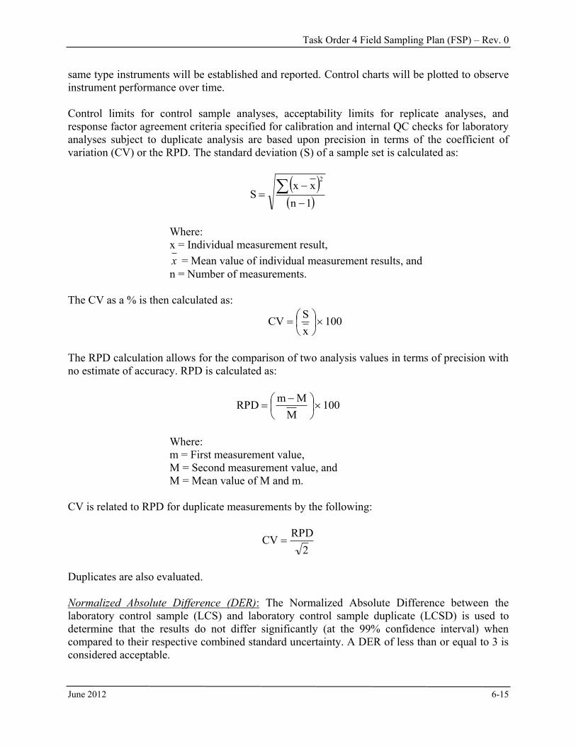
Task Order 4 Field Sampling Plan (FSP) – Rev. 0
June 2012 6-15
same type instruments will be established and reported. Control charts will be plotted to observe instrument performance over time. Control limits for control sample analyses, acceptability limits for replicate analyses, and response factor agreement criteria specified for calibration and internal QC checks for laboratory analyses subject to duplicate analysis are based upon precision in terms of the coefficient of variation (CV) or the RPD. The standard deviation (S) of a sample set is calculated as:
1n
xxS
2
Where: x = Individual measurement result, x = Mean value of individual measurement results, and n = Number of measurements.
The CV as a % is then calculated as:
100xSCV
The RPD calculation allows for the comparison of two analysis values in terms of precision with no estimate of accuracy. RPD is calculated as:
100M
MmRPD
Where: m = First measurement value, M = Second measurement value, and M = Mean value of M and m.
CV is related to RPD for duplicate measurements by the following:
2RPDCV
Duplicates are also evaluated. Normalized Absolute Difference (DER): The Normalized Absolute Difference between the laboratory control sample (LCS) and laboratory control sample duplicate (LCSD) is used to determine that the results do not differ significantly (at the 99% confidence interval) when compared to their respective combined standard uncertainty. A DER of less than or equal to 3 is considered acceptable.

Task Order 4 Field Sampling Plan (FSP) – Rev. 0
June 2012 6-16
2D
2S CSUCSU
DSDER
Where: S = LCS result D = Duplicate result CSUS = Combined Standard Uncertainty of the LCS CSUD = Combined Standard Uncertainty of the duplicate
Note: A TEST VALUE OF ‘3’ CORRESPONDS TO A 99+% CONFIDENCE LEVEL. 6.7.2 Accuracy Accuracy addresses the potential for bias and lack of precision in laboratory analytical results and is typically monitored through the use of standards, spikes, blanks, and control charts, as appropriate, depending on the method. The accuracy requirement for off-site laboratory analyses set in the CSAP is a relative standard error of 10%, as measured at the CGw value, after correcting for precision. Two types of analytical check samples can be used: LCS (a blank spike) and MS. Analytical accuracy is expressed as the % recovery of an analyte that has been added to the control samples or a standard matrix (e.g., blank soil, analyte-free water, etc.) at a known concentration prior to analysis. The accuracy of data is typically summarized in terms of relative error (RE). This calculation reflects the degree to which the measured value agrees with the actual value, in terms of % of the actual value. RE is calculated as:
100ValueActual
ValueActualValueMeasuredRE%
This way of expressing accuracy allows for a comparison of accuracy at different levels (e.g., different concentrations) and for different parameters of the same type (e.g., different compounds analyzed by the same method). Control sample analyses are typically evaluated using this calculation. Another calculation is frequently used to assess the accuracy of a procedure. Percent recovery is a calculation used to determine the performance of many of the QC checks, where:
100ValueActual
ValueMeasuredRecovery%
Another similar calculation used to determine the performance of a method for recovery of a spike concentration added to a sample is the % spike recovery calculation. The % spike recovery is determined as:
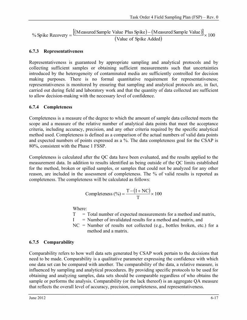
Task Order 4 Field Sampling Plan (FSP) – Rev. 0
June 2012 6-17
100AddedSpikeofValue
ValueSampleMeasuredSpikePlusValueSampleMeasuredRecoverySpike%
6.7.3 Representativeness Representativeness is guaranteed by appropriate sampling and analytical protocols and by collecting sufficient samples or obtaining sufficient measurements such that uncertainties introduced by the heterogeneity of contaminated media are sufficiently controlled for decision making purposes. There is no formal quantitative requirement for representativeness; representativeness is monitored by ensuring that sampling and analytical protocols are, in fact, carried out during field and laboratory work and that the quantity of data collected are sufficient to allow decision-making with the necessary level of confidence. 6.7.4 Completeness Completeness is a measure of the degree to which the amount of sample data collected meets the scope and a measure of the relative number of analytical data points that meet the acceptance criteria, including accuracy, precision, and any other criteria required by the specific analytical method used. Completeness is defined as a comparison of the actual numbers of valid data points and expected numbers of points expressed as a %. The data completeness goal for the CSAP is 80%, consistent with the Phase 1 FSSP. Completeness is calculated after the QC data have been evaluated, and the results applied to the measurement data. In addition to results identified as being outside of the QC limits established for the method, broken or spilled samples, or samples that could not be analyzed for any other reason, are included in the assessment of completeness. The % of valid results is reported as completeness. The completeness will be calculated as follows:
100T
NCIT(%)ssCompletene
Where: T = Total number of expected measurements for a method and matrix, I = Number of invalidated results for a method and matrix, and NC = Number of results not collected (e.g., bottles broken, etc.) for a
method and a matrix. 6.7.5 Comparability Comparability refers to how well data sets generated by CSAP work pertain to the decisions that need to be made. Comparability is a qualitative parameter expressing the confidence with which one data set can be compared with another. The comparability of the data, a relative measure, is influenced by sampling and analytical procedures. By providing specific protocols to be used for obtaining and analyzing samples, data sets should be comparable regardless of who obtains the sample or performs the analysis. Comparability (or the lack thereof) is an aggregate QA measure that reflects the overall level of accuracy, precision, completeness, and representativeness.

Task Order 4 Field Sampling Plan (FSP) – Rev. 0
June 2012 6-18
Data collection will use a variety of on-site and field-based data collection methods. A component of field data collection will be to establish site-specific performance for these methods to ensure data of sufficient quality to satisfy decision-making requirements.

Task Order 4 Field Sampling Plan (FSP) – Rev. 0
June 2012 7-1
7.0 REFERENCES
1. Phase 1 Decommissioning Plan for the West Valley Demonstration Project, Washington Safety Management Solutions, URS Washington Division, and Science Applications International Corporation, December 2009.
2. Task Order 4 Scope of Work, Contract DE-EM-0001242, March 2012.
3. Phase 1 Final Status Survey Plan for the West Valley Demonstration Project, Argonne National Laboratory Environmental Science Division, 9700 South Cass Avenue, Argonne, IL 60439, May 2011.
4. Phase 1 Characterization Sampling and Analysis Plan, West Valley Demonstration Project,
Argonne National Laboratory Environmental Science Division, 9700 South Cass Avenue, Argonne, IL 60439, June 2011.
5. HLW Canister Interim Storage Area, West Valley Demonstration Project, New York, Subsurface Soils Characterization Report, March 2012.
6. Multi-Agency Radiation Survey and Site Investigation Manual, Rev. 1, NUREG 1575, August 2000.
7. The Procedures Manual of the Environmental Measurements Laboratory, 28th Edition, February, 1997.

Task Order 4 Field Sampling Plan (FSP) – Rev. 0
June 2012
APPENDIX A
Gamma Walkover Procedure

SEC SOP Radiological Operations Revision 0 Radiation Survey of Open Lands Utilizing GPS at WVDP page-1-
1.0 Definitions A gamma walkover survey refers to the practice of walking or driving over a land surface and scanning for gamma anomalies or areas of elevated count rates. Global Positioning System (GPS) is method of land surveying utilizing satellites to provide an accurate land position. Differential Global Positioning (DGPS) is an accurate measurement of the relative positions of two receivers tracking the same GPS signals. The roving receiver collects the survey data, while a fixed or receiver (base station) collects data simultaneously. The base station broadcasts a fixed position based on the errors it records in it position versus its actual location. 2.0 Applicability This SOP provides guidance on completing characterization surveys of open lands using gamma walkover scanning in combination with a global positioning system. The procedure provides the information necessary to produce initial site characterizations and data packages. Survey packages will be assembled under the Work Plan. This procedure directs the performance of individual surveys. 3.0 References 3.1 Differential GPS Explained Trimble, 1993 3.2 DOE O 458.1 Radiation Protection of the Public and the Environment. 3.3 10CFR835 Occupational Radiation Protection 3.4 MARSSIM Multi-Agency Radiation Survey and Site Investigation
Manual 4.0 Notes and Precautions 4.1 The objective of the task is to delineate and map the existing radiation levels over a
specified area. 4.2 Radiological instrumentation types should remain constant throughout the survey.
Radiological instrumentation should be determined based on the radionuclides of interest. 4.3 The measurement method affects the scan path spacing. For example, a walking scan
with approximately one meter of detector swing, covers a one meter wide strip and the spacing between path should be one meter. Surveying should be conducted with the goal of collecting at least one measurement every square meter.
4.4 If multiple probes are used to collect data in the same survey, a 100 m2 area at the site
will be surveyed with each detector. Data will be normalized according to Section 5.3 of the Phase 1 West Valley Demonstration Project (WVDP) Final Status Survey Plan (FSSP).
4.5 If necessary, the survey may be conducted in two perpendicular directions or with a
mixture of riding and walking. For example, a survey area might be surveyed with a North-South pattern, but geography inhibits 100% coverage of a subarea. In this case, the subarea might then be surveyed again in an East-West pattern or the subarea in question
SEC SOP Radiological Operations Revision 0 Radiation Survey of Open Lands Utilizing GPS at WVDP page-2-
might be surveyed by walking. If the survey unit is less than one acre and the method is driving, consider driving the area twice with perpendicular directions to ensure 100% coverage.
5.0 Gamma Walkover Surveys in Concert with GPS Navigational Systems 5.1 Background Determination
A reference area should precede the initial characterization to ensure that instruments and recorders are operable, and that reporting systems are appropriate, per the following guidance.
1) The reference area will be surveyed with the detector and data will be logged
consistent with protocols to be used for final status survey (FSS) data collection purposes. These data will be reviewed and compared with existing data sets from similar detectors (if available) to confirm consistency in general detector behavior (average gross activity concentration recorded and observed variability in detector response).
2) Quality Control (QC) data will be obtained from a fixed QC point at a height of six
inches above exposed soils from a point established for this purpose outside any areas expected to be remediated. These data will be used to construct a control chart that can be used for QC purposes for subsequent deployments of the detector as part of FSS work.
5.2 Daily Quality Control
1) A stationary reading will be taken from the QC point at the start and end of each day a detector is in use. These QC data will be compared to the control chart to determine that the detector response is consistent with historical responses from that location. If a QC measurement results in a detector response “out of control” at the start of the day, the measurement will be repeated. If the subsequent measurement is still out of control, the reason for the discrepancy will be established before the detector is used. If the out-of-control event occurs at the end of the day and is verified by a subsequent measurement, the reason for the discrepancy will be established before the data collected that day with that detector are considered acceptable for FSS purposes. “Out of control” is defined as a result that is more than two standard deviations above or below the average historical detector response at that control point.
2) Electronically logged data will be reviewed for completeness (e.g., evidence of
spatial “holes” in collected data), evidence of erratic detector behavior (e.g., sequential readings during a moving survey that show a marked increase or decrease in gross activity not confirmed by spatially adjacent measurements), or evidence of shine (e.g., systematically elevated readings proximal to structures, buildings, soil piles, storage units or excavated soil walls). In the case of incomplete data, data collection will be conducted to fill the gap. In the event of erratic behavior, the cause will be investigated, suspect data will be flagged as such, and additional data collection will be conducted to address affected areas as appropriate.

SEC SOP Radiological Operations Revision 0 Radiation Survey of Open Lands Utilizing GPS at WVDP page-3-
5.3 Site Specific Information
Data presentation should be considered prior to collection of data. Ensure that the correct coordinate system used. The data format will be GPS coordinates in NAD 1983 State Plane New York West FIPS 3103.
5.4 Establishing a Daily Survey Area
The daily survey area will depend on the topography and landmarks of the survey unit. The objective is to systematically survey all anomalies or random survey units in each Grid Unit. The survey supervisor will assign data packages. Ensure that the coordinates and photographs match the actual field survey conditions. Cover the survey unit with a maximum one m path spacing at speeds not to exceed 0.5 m/s.
6.0 Data Quality and Presentation 6.1 To ensure the accuracy of GPS survey, files must be differentially corrected. Differential
correction is a means of comparing data from a roving receiver with a base station. The base station continuously collects positional information. These observed positions are compared to a known coordinate. The difference between the observed position and the actual position is error cause by the atmosphere or selectively induced errors. Differential correction applies the same offsets to increase the accuracy of the roving receiver.
6.2 Data will be plotted using ArcView in one second increments and organized in a
spreadsheet form. 6.3 The daily data submittal will include field notes, quality control tests, and survey
graphics.


Task Order 4 Field Sampling Plan (FSP) – Rev. 0
June 2012
APPENDIX B
Geoprobe Procedure

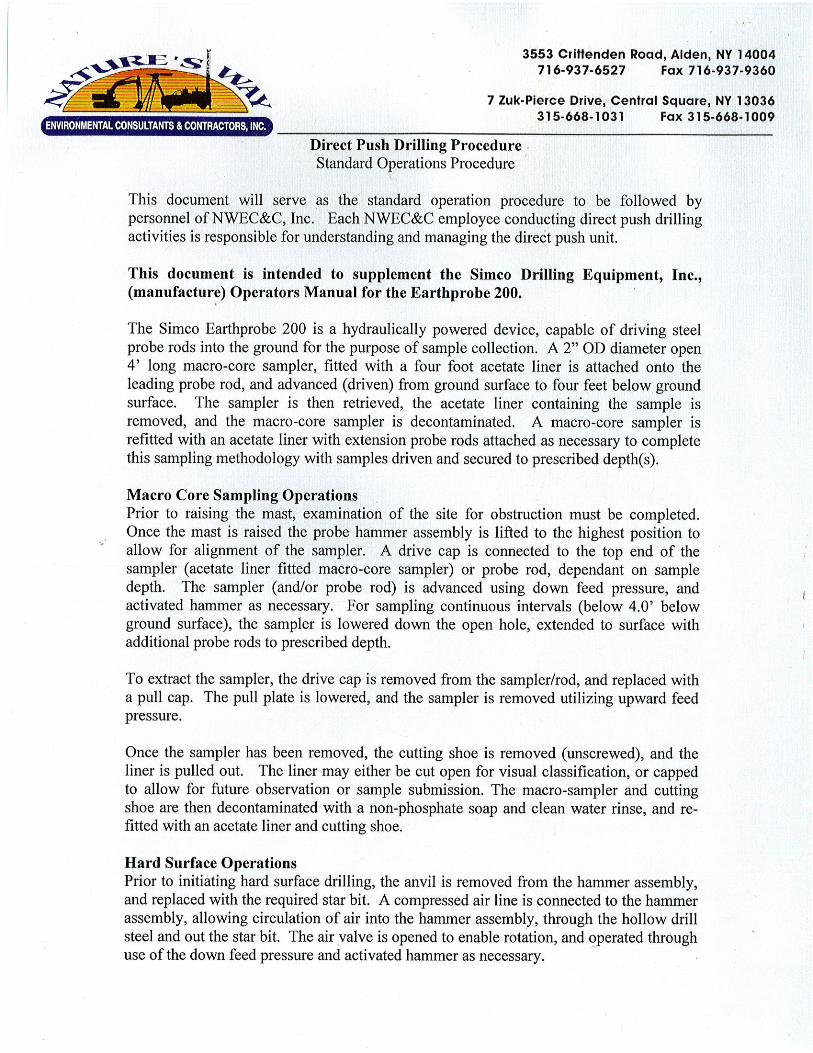

Task Order 4 Field Sampling Plan (FSP) – Rev. 0
June 2012
APPENDIX C
Soil Sampling Procedure


Safety and Ecology Corporation SEC-EM-305 Soil Sampling Revision 3
June 2012 Page 1 of 6
1 SEC-EM-305, Revision 3 June 2012
1.0 PURPOSE
The objective of this procedure is to detail the appropriate methods for the collection of surface and subsurface soil samples.
2.0 SCOPE
This procedure applies to the collection of surface and subsurface soil samples for trace contaminant analysis, which includes volatile organic compounds (VOC), semi-volatile organic compounds (SVOC), pesticides/PCBs (collectively, organic compounds), metals (inorganic), and radiological analyses. Sampling locations, depths and intervals should be defined in the Field Sampling Plan (FSP). Samples for geotechnical or other analyses not considered trace analyses do not need to meet requirements for trace contaminant analyses sampling.
3.0 REFERENCES AND DEFINITIONS
3.1 References
SEC-ISMS, Integrated Safety Management System EPA/R04/SOP/NRN-9102, 1996, “Environmental Investigations Branch Standard Operating Procedures and
Quality Assurance Manual,” Athens, GA 29 CFR 1910.120 40 CFR Part 136 Table II SEC-EM-309
3.2 Definitions
Surface soil sample: a soil sample that includes the upper interval or surface material (typically 0-15cm). Subsurface soil sample: a soil sample that is collected from soils that is below ground surface (typically 15-
100 cm)
4.0 GENERAL
4.1 Responsibilities
4.1.1 Project Manager or Designee
The Project Manager or designee is responsible for obtaining the sample in compliance with this procedure and the Field Sampling Plan (FSP). It is also the responsibility of the Project Manager or designee to follow all requirements for sample containers and holding times, maintaining chain of custody (COC), documenting sampling activities, and quality assurance as required by other procedures.
4.1.2 Radiological Engineer (Sampling Team Lead)
The Sampling Team Lead is the primary supervisor of the sampling team and is responsible for: Providing technical direction for the collection of samples and subsequent analyses, field measurements, and
field tests Overall team supervision Obtaining copies of the appropriate work-controlling documents Fully understanding this sampling procedure Maintaining the field logbook and/or relevant field data acquisition forms Responsible for assuring the COC forms are completed and maintained Maintaining data quality
Safety and Ecology Corporation SEC-EM-305 Soil Sampling Revision 3
June 2012 Page 2 of 6
2 SEC-EM-305, Revision 3 June 2012
Obtaining all field Quality Control (QC) samples as specified in this procedure Maintaining sampling instructions while in the field, including confirmation or performance of functional
requirements Checks/proper calibration as required by procedure and/or instrument manufacturer instructions
4.1.3 Sampling Technician
Sampling Technician(s) shall receive all instructions from the Sampling Team Lead and actually implement the procedurally prescribed work processes.
4.2 Prerequisites
Personnel collecting samples shall be trained in the use of the specific equipment outlined in this procedure. All sampling personnel shall have the requisite medical examinations, training, and site-specific training in accordance with 29 CFR 1910.120 as described in the Safety and Ecology Corporation (SEC) ISMS and implementing plans and procedures. All waste management and ES&H practices shall follow applicable SEC work controlling documents.
4.3 Precautions
Samples are to be considered potentially contaminated. The following precautions shall be taken: Avoid contact with the sample media Wear boots and phthalate-free rubber or plastic gloves Wear eye protection Do not transfer contaminants to other surfaces
Some contaminants can be detected in the parts per billion and/or parts per trillion ranges. Extreme care shall be taken to prevent cross-contamination of these samples. The following precautions shall be taken when trace contaminants are of concern:
Sampling equipment used for sampling for trace contaminants should be constructed of glass, Teflon, or stainless steel where possible. Plastic equipment should be generally avoided except for inorganic contaminants. Sampling equipment and containers shall be protected from sources of contamination prior to use.
Sampling equipment should be properly decontaminated in accordance with Procedure SEC-EM-309 prior to use.
Stage sampling equipment and supplies on plastic sheeting or equivalent to prevent contact with potentially contaminated surfaces. Don a new pair of disposable gloves immediately prior to sampling.
Samples suspected of containing high concentrations of contaminants shall be placed in separate plastic bags and shall not be stored with environmental samples.
Sample collection activities should proceed progressively from the suspected least contaminated area to the suspected most contaminated area when possible.
Some sample tags are equipped with wire ties. Wire ties can rust and/or contaminate the neck and threaded area of sample containers and contaminate the sample. Therefore, wire ties shall not be used.
4.4 Apparatus
While site-specific requirements may vary, apparatus may include: Stainless steel hand auger or other soil sampling device Stainless steel spoon and bowl (or Pyrex glass pan) Decontamination equipment Aluminum foil or plastic sheeting (for laying clean equipment on) Chemically resistant surgical gloves (i.e., rubber, vinyl, neoprene, etc.) Appropriate containers, tags/labels, and custody seals

Safety and Ecology Corporation SEC-EM-305 Soil Sampling Revision 3
June 2012 Page 3 of 6
3 SEC-EM-305, Revision 3 June 2012
COC record and logbook Sample cooler, plastic bag, and paper towels Packing materials HNU/OVA type detector (as appropriate per ES&H plan)
4.5 Records
Chain of Custody record and logbook(s) shall be used to document sample collection. Any data generated from these samples shall be included in the project records’ management files. Any end-user data assessment shall also be maintained in the records’ management files.
5.0 PROCEDURE
The following is applicable unless otherwise specified in specific work-controlling documents.
5.1 Environmental Safety and Health Guidelines
All environmental safety and health requirements, as listed in the applicable ES&H Plan, shall be met before sampling may proceed. Equipment and supplies shall be handled and/or staged to avoid or minimize contact with potentially contaminated surfaces. When handling onsite surface waters, groundwater, soils, debris, or waste materials, chemically protective gloves shall be worn.
5.2 Sample Identification
Sample containers must be labeled, tagged or marked showing sample identification. Temporarily unmarked samples (in sampling devices, unlabeled jars, etc.) shall not be placed in the vicinity of other similar unmarked samples. Sample data can be invalidated if sample identification is not clear. Documentation of the sample, sampling activity, and sample handling shall be in accordance with the pertinent SAP and procedures.
5.3 Soil Sampling Procedures
A variety of soil sampling tools, typically made of stainless steel, are available for collection of soil samples (e.g., hand augers, split spoons, coring devices, scoops, spoons, etc.). Boreholes for subsurface soil samples may be advanced by hand boring devices (hand augers), portable powered augers, drilling rig, Geoprobe®, or hammering equipment. This procedure primarily references hand augers but is applicable to other soil sampling equipment.
5.3.1 Sample Collection
1) For surface soil samples (i.e., 0-15 cm, 0-100 cm): a) Using a stainless steel hand auger or other soil sampling device (which has been decontaminated), auger,
push, or core into the material that is being sampled, to the depth specified in the FSP, and retrieve the sample.
2) For subsurface soil samples: a) Using a hand auger or other boring or drilling, or sampling device (which has been decontaminated),
advance the borehole or sample device to the appropriate sampling depth. Use a decontaminated hand auger or sampling device, such as a thin walled tube or split spoon sampler, to collect the sample. Prior to collecting the sample, remove and/or minimize cuttings/cavings from the borehole to avoid collection of material that is not from the sampling interval. After retrieving the sampler, trim the upper portion of the sample to remove any cuttings or cavings that may be present with the sample. OR
b) Using a cone penetrometer, or Geoprobe® rig with a split-spoon sampler, push to above the desired depth using a dummy one. Retract the rod and replace the dummy cone with the sampler. Push to below the desired depth to collect the sample. Retract the rod and sampler. Open the two halves of the split spoon and remove the sample. Trim the upper portion to remove any carvings that might be present. OR
c) Using a backhoe to remove soil from the excavation, use a stainless steel trowel to collect soil not in contact with the bucket surface and place it in the pan (or sample container if VOC analyses are to be conducted on the sample).

Safety and Ecology Corporation SEC-EM-305 Soil Sampling Revision 3
June 2012 Page 4 of 6
4 SEC-EM-305, Revision 3 June 2012
3) Samples for VOC analysis should be collected first, without mixing, and placed directly into the appropriate (septa lid) sample container leaving no head space. Care should be taken when filling the container to disturb the sample as little as possible. a) These samples shall be collected in a manner that minimizes loss of VOCs. b) The VOC sample may be collected directly from the sampling device or immediately after the soil is
emptied into the pan. c) VOC samples should be containerized immediately upon retrieval.
4) Mix the remaining soil in the bowl or pan by quartering the sample, mixing each quarter, and mixing all quarters together. With the exception of VOC samples, it is important that soil samples be mixed as thoroughly as possible to ensure that the sample is representative of the sample interval. A common method of mixing is referred to as quartering: a) The soil in the sample pan is divided into quarters. b) Each quarter is mixed, and then all quarters are mixed into the center of the pan. c) This procedure is followed several times until the sample is adequately mixed. d) If round bowls are used for sample mixing, adequate mixing is achieved by stirring the material in a
circular fashion and occasionally turning the material Note:
If samples are predominantly moist and clayey (i.e., cohesive), extra effort may be necessary to produce a homogenous mixture.
5) Fill and cap the remaining sample containers, leaving about 10% head space, and wipe the exteriors of the containers to remove any potential residue.
6) Label or tag the containers as appropriate and custody seal the closure. Place the containers in plastic bags and chill the samples on ice in a sample cooler (or equivalent) as soon as practical for storage and/or transport. It is not necessary to chill samples only for inorganic radionuclides.
7) Document sampling activities, including sample depth and interval, in the field logbook and CO form.
5.4 Quality Assurance/Quality Control Requirements
All provisions of the applicable Quality Assurance Project Plan shall be followed during sampling activities, including collection of appropriate number and types of QC samples. Verify that all equipment has been properly decontaminated prior to sampling. After sampling verify that samples are properly labeled and preserved, and the chain-of-custody forms are completed.
5.4.1 Quality Control Samples
This section describes various additional samples that are required for field sampling quality control. The quality control samples shall be collected and handled taken at the same time and in the same manner as the other samples.
5.4.1.1 Field Duplicate Sample
The time and location of the field duplicate samples will be designated by the sampling team lead. The duplicate sample will be taken at a frequency of at least five percent (one for every 20 samples taken) and be analyzed for the same analyte as the original sample.
A field duplicate will be collected by taking half of the soil sampled from the selected sampling interval after homogenization as described above in Section 5.3.1, 4. This duplicate will be collected in the same manner as the original sample.
5.4.1.2 Matrix Spike
A matrix spike will be collected when samples are collected for chemical parameter analyses and consist of a triple volume from one sample location. Regulatory authority or project-specific requirements will determine whether radiological analyses require matrix spikes. See project specific FSP or other work controlling document for project-specific QC requirements.

Safety and Ecology Corporation SEC-EM-305 Soil Sampling Revision 3
June 2012 Page 5 of 6
5 SEC-EM-305, Revision 3 June 2012
Note:
The triple volume shall be separated into three individual containers. The three individual containers enable the laboratory to perform the analysis on the original sample and on two samples that the lab “spikes.” These are the “matrix spike” and “matrix spike duplicate.”
A matrix spike/matrix spike duplicate shall be collected from at least one sampling location for every 20 locations sampled.
5.4.1.3 Trip Blanks – FOR CHEMICAL (VOLATILE ORGANIC ANALYSES) ONLY
Trip blanks will meet the following requirements:
1) Prepared and used whenever collecting samples for volatile organic analyses (not required for other analyses),
2) Prepared using analyte-free water prior to the sampling event and are kept with the investigative samples throughout the sampling event,
3) Be sealed in 40 ml glass vials with Teflon lined septum caps, 4) Completely filled vials with no headspace, and 5) Shall be sent to the laboratory for analysis at a frequency of one per day and must be shipped to the analytical
subcontractor with all samples associated to the trip blank. It does not matter in which cooler it is shipped. Note:
One trip blank consists of two 40 ml vials of analyte-free water. Rinse and trip blanks do not require separate matrix spike analyses.
5.4.1.4 Rinse Blanks
A rinse blank shall meet the following requirements:
1) Rinse blanks are not required for radiological soil samples except for tritium. 2) A rinse blank should be obtained by collecting demonstrated analyte-free water that has been poured into,
over, and/or pumped through decontaminated sampling equipment that will be used to sample, 3) Be analyzed for all analyte of interest (determined prior to the sampling event by the characterization lead or
designee), 4) Be required for non-dedicated pumps and tubing, 5) Be required for filtration devices (excluding the filter), 6) It is permissible to use the same aliquot of water on all equipment associated with a particular sample matrix
and analysis, 7) If tritium is being measured, a tritium blank, made of the water used for rinse blanks, should be submitted
along with the rinse blank to quantify the amount of tritium in the blank, and 8) A minimum of one rinse blank will be required for every 20 samples or approximately 5% of the total number
of samples at a minimum of one per matrix (i.e., soil). Note:
Rinse and trip blanks do not require separate matrix spike analyses.
5.5 Waste Disposal
Waste generated from sampling operations will be managed as required by the FSP, WMP, or other work-controlling document.
6.0 APPENDICES
6.1 Recommended Containers, Holding Times, and Preservation

Safety and Ecology Corporation SEC-EM-305 Soil Sampling Revision 3
June 2012 Page 6 of 6
A-1 SEC-EM-305, Revision 3 June 2012
Appendix A
Recommended Containers, Holding Times, and Preservation1
ANALYSIS SOIL/SEDIMENT
Container Preservative Holding Time Radionuclides (except H-3/C-14) 8G or naglene N/A 180 Tritium/C-14 8G Ice (4 o C) 45
Pre-Cleaned Containers: 8G - 8 oz. wide mouth glass (Teflon lid). Nalgene bottles up to 1000 ml or larger may be used.
Holding Times: in days

Task Order 4 Field Sampling Plan (FSP) – Rev. 0
June 2012
APPENDIX D
Laboratory Requests and Chain of Custody


Safety and Ecology Corporation SEC-EM-308 Laboratory Requests and Chain of Custody Revision 3
March 2012 Page 1 of 3
1 SEC-EM-308, Revision 3 March 2012
1.0 PURPOSE
This document is designed to provide guidance for the identification and documentation of the possession history of a sample from collection through analysis by using the appropriate laboratories’ Request and Chain of Custody Forms.
2.0 SCOPE
This procedure applies to all samples that are collected for laboratory analysis in support of SEC Field Projects.
3.0 REFERENCES AND DEFINITIONS
3.1 References
Title 10, Energy, Code of Federal Regulations (CFR), Part 830, Nuclear Safety Management, Section 120, Quality Assurance Requirements
Department of Energy (DOE) Order 414.1D, Quality Assurance American Society of Mechanical Engineers (ASME), Nuclear Quality Assurance (NQA)-1, Quality
Assurance Program Requirements for Nuclear Facilities
3.2 Definitions
Custody: a sample that is in a particular individual’s custody if it is in that person’s physical possession, in view of the person who takes possession, secured by that person so that no one can tamper with it, or secured by that person in an area to which access is restricted to authorized personnel.
Chain of Custody: an unbroken trail of accountability that ensures the physical security of samples, data, and records
Laboratory Request Form: a record that identifies requested sample analysis.
4.0 GENERAL
4.1 Discussion
The laboratories analyzing the field samples should provide Laboratory Request Forms and Chain of Custody Forms. This procedure provides guidance on handling and completing these forms. Each time the samples are transferred to another custodian, signatures of the persons relinquishing the sample and receiving the sample, the reason for relinquishing the sample, the time, and date shall be documented.
Records for sampling activities shall be maintained in project records’ management files. These records shall be retained as part of the project record. Logbook and other documents, if used for sampling activities, shall also be maintained as project records’ management files.
4.2 Responsibilities
The individual who collects and packages the samples or the appropriate group leader is responsible for completing the Chain of Custody section of the Request for Analytical Services Request form.
Any individual who takes custody of the samples is responsible for completing the appropriate area(s) of the form.
The Sampling Team Lead is responsible for reviewing all field activities to ensure that prescribed custody procedures were followed.
Safety and Ecology Corporation SEC-EM-308 Laboratory Requests and Chain of Custody Revision 3
March 2012 Page 2 of 3
2 SEC-EM-308, Revision 3 March 2012
5.0 PROCEDURE
5.1 Completing the Request for Analytical Services Form
The Laboratory Request Form, SEC-EM-308-F01, is included with this plan as an example. The forms provided by the actual laboratories performing the analyses should look similar. Each area of these forms needs to be completed. If one of these laboratory forms has not provided, use the form attached to this procedure (Form SEC-EM-308-F01).
Complete the Request for Analytical Services Form as follows 1) Date: The date the laboratory request is completed. 2) Shipped To: The address of the vendor laboratory 3) Priority: Select the turn-around required on the sample analysis. This should be cleared
through the project cost manager before completing the form. 4) Special
Instructions: Provide the vendor any special instructions.
5) Sample ID: The site-specific sample identification numbering system. 6) Location ID: This may be used to further specify the sample location data. This can be a building
number, room number, coordinate, or any other designator that is useful to the site. 7) Sample Date: The sample collection date. 8) Analysis: The analysis requested from the vendor. Often, the analysis requested may be pre-
selected. 9) Matrix: The media from which the sample is collected (i.e., soil, water, paint scrapings,
swipes, air samples, oil, sediment, etc.). 10) Comments: Used to provide additional sample parameters. This could be information on quality
control, (i.e., duplicate, trip sample, blank, spike, rinsate, etc.). 11) Sampled By: The person who collected the samples or who oversaw the collection of samples. 12) Date: The date of the sample collection. 13) Signature: Signature of the person who collected the sample. 14) Project Manager: Person who has the authority to authorize the expenditure of funds to pay for the
analysis. 15) Project Group
Leader Signature verifies that the technical attributes of the request have been correctly completed.
5.2 Completing the Chain of Custody Section
16) Signatures: The signatures of the person transferring custody and the person receiving custody are required on the Chain of Custody. The time and date of the signatures is also required.
17) Comments: The lower comments box may be used to specify analysis specifics or other shipping requirements.
18) Package Dose Rate: Documents that the package containing the sample meets the requirements for a limited-quantity shipment.
19) Instrument: The technician completing the form should enter the instrument model and serial number.
20) Technician: The technician completing the dose rate.
6.0 APPENDICE
6.1 Appendix A - Laboratory Request and Chain of Custody, Form EM-308-01
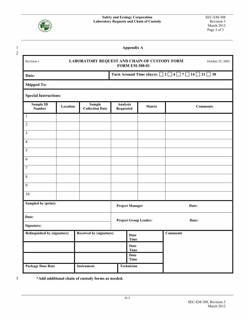
Safety and Ecology Corporation SEC-EM-308 Laboratory Requests and Chain of Custody Revision 3
March 2012 Page 3 of 3
A-1 SEC-EM-308, Revision 3 March 2012
Appendix A 1 2
Revision 1 LABORATORY REQUEST AND CHAIN OF CUSTODY FORM October 25, 2002 FORM EM-308-01
Date: Turn Around Time (days): 2 4 7 14 21 30
Shipped To:
Special Instructions:
Sample ID Number Location Sample
Collection Date Analysis
Requested Matrix Comments
1
2
3
4
5
6
7
8
9
10
Sampled by (print):
Project Manager Date:
Date: Project Group Leader: Date:
Signature:
Relinquished by (signature) Received by (signature) Date Time
Comments
Date Time
Date Time
Package Dose Rate Instrument Technician
*Add additional chain of custody forms as needed. 3

Task Order 4 Field Sampling Plan (FSP) – Rev. 0
June 2012
APPENDIX E
Sample Log Sheet


Easting (x)
Northing (y)
Elevation (Z)
Am-241 Np-237 Tc-99
PDOP: C-14 Pu-238 U-232
Cm-243 Pu-239 U-233
Cm-244 Pu-240 U-234
Cs-137 Pu-241 U-235
I-129 Sr-90 U-238
Ac-227 H-3 Sb-125
Co-60 Pa-231 Sn-126
Cd-113m Ra-226 Th-229
Eu-154 Ra-228 Th-232
Rev. 03/05/12
West Valley Demonstration Project Sample Log Sheet
Notes: Please include sample description, reasons for taking, general location information, etc.
Internal Custody:
Sampler
(Relinquished
By)
Date/Time
Received By Date/TimeSign
Chain of Custody if Offsite Laboratory
Laboratory:
SignPrint
Laboratory Instructions:Onsite Laboratory (Y/N)
Offsite Laboratory (Y/N)
Radionuclides for Analysis
Depth Relative to Ground
Surface (Start Depth)End Depth
Date / Time
In-Situ Count Rate (cpm)
ProXR/ProXT
Model Number:
Serial Number:
Instrument Information
Sample Identification
Backpack (circle one) or
Surveyor (circle one) Total Station / GPS
Position Description
Calibration Due:
Instrument
Detector
Model Number:
Serial Number:
Calibration Due:
12 Potential Radionuclides of Concern
(Circle)
18 Radionuclides of Concern (Circle)

Task Order 4 Field Sampling Plan (FSP) – Rev. 0
June 2012
APPENDIX F
Cooler Receipt Checklist

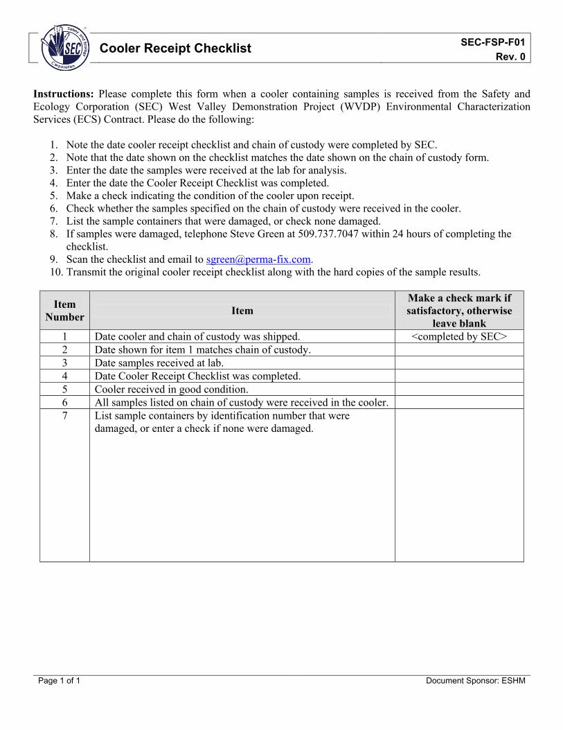
Cooler Receipt Checklist SEC-FSP-F01 Rev. 0
Page 1 of 1 Document Sponsor: ESHM
Instructions: Please complete this form when a cooler containing samples is received from the Safety and Ecology Corporation (SEC) West Valley Demonstration Project (WVDP) Environmental Characterization Services (ECS) Contract. Please do the following:
1. Note the date cooler receipt checklist and chain of custody were completed by SEC. 2. Note that the date shown on the checklist matches the date shown on the chain of custody form. 3. Enter the date the samples were received at the lab for analysis. 4. Enter the date the Cooler Receipt Checklist was completed. 5. Make a check indicating the condition of the cooler upon receipt. 6. Check whether the samples specified on the chain of custody were received in the cooler. 7. List the sample containers that were damaged, or check none damaged. 8. If samples were damaged, telephone Steve Green at 509.737.7047 within 24 hours of completing the
checklist. 9. Scan the checklist and email to [email protected]. 10. Transmit the original cooler receipt checklist along with the hard copies of the sample results.
Item Number Item
Make a check mark if satisfactory, otherwise
leave blank 1 Date cooler and chain of custody was shipped. <completed by SEC> 2 Date shown for item 1 matches chain of custody. 3 Date samples received at lab. 4 Date Cooler Receipt Checklist was completed. 5 Cooler received in good condition. 6 All samples listed on chain of custody were received in the cooler. 7 List sample containers by identification number that were
damaged, or enter a check if none were damaged.
