fidelity analysis for the oh-58d kiowa warrior crew trainer · technical report 1083 fidelity...
TRANSCRIPT

Technical Report 1083
Fidelity Analysis for the OH-58D Kiowa Warrior Crew Trainer
John E. Stewart II U.S. Army Research Institute
Kenneth D. Cross Bayview Research
Robert H. Wright U.S. Army Research Institute
June 1998
19980622 130 United States Army Research Institute for the Behavioral and Social Sciences
Approved for public release; distribution is unlimited.
U.S. Army Research Institute for the Behavioral and Social Sciences
A Directorate of the U.S. Total Army Personnel Command
EDGAR M. JOHNSON Director
Technical Review by
William R. Howse, ARI John A. Dohme, ARI
NOTICES
DISTRIBUTION: Primary distribution of this Technical Report has been made by ARI. Please address correspondence concerning distribution of reports to: U.S. Army Research Institute for the Behavioral and Social Sciences, Attn: TAPC-ARI-PO, 5001 Eisenhower Ave., Alexandria, VA 22333-5600.
FINAL DISPOSITION: This Technical Report may be destroyed when it is no longer needed. Please do not return it to the U.S. Army Research for the Behavioral and Social Sciences.
NOTE: The findings in this Technical Report are not to be construed as an official Department of the Army position, unless so designated by other authorized documents.
REPORT DOCUMENTATION PAGE
1. REPORT DATE (dd-mm-yy)
June 1998 2. REPORT TYPE Final
3. DATES COVERED March 1997 - February 1998
4. TITLE AND SUBTITLE
Fidelity Analysis for the OH-58D Kiowa Warrior Crew Träner
5a CONTRACT OR GRANT NUMBER
MDA903-87-C-0802
5b. PROGRAM ELEMENT NUMBER 622785
6. AUTHOR(S) John E. Stewart, II (ARI), Kenneth D. Cross (Bayview Research), and Robert H. Wright (ARI)
5c. PROJECT NUMBER A791
5d. TASK NUMBER 2211
5e. WORK UNIT NUMBER WP2211
7. PERFORMING ORGANIZATION NAME(S) AND ADDRESS(ES) 8. PERFORMING ORGANIZATION REPORT NUMBER
Bayview Research 117 Lisa Marie Place Shalimar, FL 32579
US Army Research Institute Rotary-Wing Aviation Research Unit Bldg. 5100 Ft. Rucker, AL 36362-5354
9. SPONSORING/MONITORING AGENCY NAME(S) AND ADDRESS(ES) U.S. Army Research Institute for the Behavioral and Social Sciences 5001 Eisenhower Avenue Alexandria, VA 22333-5600
10. MONITOR ACRONYM
ARI
11. MONITOR REPORT NUMBER
Technical Report 1083
12. DISTRIBUTION/AVAILABILITY STATEMENT
Approved for public release; distribution is unlimited.
13. SUPPLEMENTARY NOTES
14. ABSTRACT (Maximum 200 words):
The Army must balance cost and training effectiveness in acquiring a Kiowa Warrior Crew Trainer (KWCT). This entails determining the least fidelity required for specific training objectives, employing the least costly technology. A fidelity analysis was conducted which involved (a) analysis of training requirements, (b) review of the literature, and (c) empirical assessment of a benchmark KWCT. Subject matter experts (SMEs) identified 13 tasks for which training in the aircraft alone was inadequate. It was concluded that the KWCT should train these tasks under the full range of visibility conditions and when affected by obscurants. The literature revealed virtually no data on display resolution required to train tasks other than target detection and identification. It also implied that a visual display system with adequate field-of-view (FOV) and resolution for target detection and identification at realistic standoff ranges would be prohibitively expensive. For the benchmark KWCT assessment, small sample size made performance evaluation difficult. Gunnery was more affected by degraded depth cues when resolution was low (480 lines), than when high (768 lines). Low resolution was perceived as inadequate for all tasks and high resolution as marginally adequate for gunnery. FOV was perceived as less critical to gunnery than to general flying.
15. SUBJECT TERMS
Simulators and part-task trainers Helicopter tactical gunnery Tactical skills sustainment
Aerial gunnery träning Selective fidelity
SECURITY CLASSIFICATION OF '■'■ '■'■'—"■' '•"■" '•"•"■ ' '■ i ■ ■'■ ■'•"■ ■ ■'—"■ -'■'■'■'■'■'■'
16. REPORT Unclassified
17. ABSTRACT Unclassified
18. THIS PAGE Unclassified
19. LIMITATION OF ABSTRACT
Unlimited
20. NUMBER OF PAGES
75
21. RESPONSIBLE PERSON (Name and Telephone Number) Dennis C. Wightman (334) 255-2834
Technical Report 1083
Fidelity Analysis for the OH-58D Kiowa Warrior Crew Trainer
John E. Stewart II U.S. Army Research Institute
Kenneth D. Cross Bayview Research
Robert H. Wright U.S. Army Research Institute
Rotary-Wing Aviation Research Unit Dennis C. Wightman, Chief
U.S. Army Research Institute for the Behavioral and Social Sciences 5001 Eisenhower Avenue, Alexandria, Virginia 22333-5600
June 1998
Army Project Number Education and Training Technology 20262785A791
Approved for public release; distribution is unlimited.
HI Preceding PageBlank
FOREWORD
The fidelity analysis discussed in this report was performed by the Aircrew Performance Team of the U.S. Army Research Institute for the Behavioral and Social Sciences (ARI) Rotary Wing Aviation Research Unit (RWARU) at Fort Rucker, Alabama. ARI RWARU is committed to enhancing aviation training in the Army. A cornerstone of this commitment is the Simulator Training Research Advanced Testbed for Aviation (STRATA). STRATA research objectives are to (1) determine the minimal levels of simulator fidelity required to meet specific training objectives, (2) define effective training strategies for flight simulator technology to attain and sustain combat readiness for individual and collective training, and (3) delineate effective ways to train for new operational equipment and tactics based on realistic simulations of battlefield environments.
The Program Manager-Kiowa Warrior (PM-KW) requested that ARI RWARU perform a fidelity analysis as a Front-End Analysis (FEA) to specify the functional and design requirements for a Kiowa Warrior Crew Trainer (KWCT). Ideally, a program of research would be conducted to compile objective data on the relationship between training effectiveness and fidelity level for each component of a proposed KWCT. Time and resources required to conduct such a research program far exceeded those available for this project. For these reasons, it was necessary to conduct the fidelity analysis using information gleaned from (a) an analytic study of training requirements, (b) a review of the open literature, and (c) an assessment of a benchmark KWCT developed from STRATA by ARI RWARU personnel.
The findings of this FEA were briefed to the PM-KW on 4 March 1998. This report illustrates how components of STRATA can be used as FEA tools for providing program managers and other key decision-makers with timely guidance on the functional requirements and tradeoffs relating to the acquisition and integration of simulators and other training devices.
ZITA M. SIMUTIS Technical Director
ACKNOWLEDGMENTS
This project would not have been possible without the concerted, dedicated efforts of key individuals. First, Mike Couch and Dale Weiler, both retired Army aviators, contributed to the development of the mission scenario and its validation. Nick Donker, Rolf Beutler, Ohannes Younanian, Fred Zalzal and other members of the CAE, Inc., STRATA team provided essential support in the integration, operation, and testing of the Kiowa Warrior Crew Trainer benchmark simulator. Thomas Preston, ARIRWARU, built many of the pages for the multifunction displays. Rande Hanson of ARI RWARU played a key role in the formatting and recording of automated performance data. Finally, we are indebted to CW03 Thomas Montgomery, an experienced OH-58D pilot, for providing us with expert guidance throughout the development of Kiowa Warrior Crew Trainer Benchmark Testbed.
VI
FIDELITY ANALYSIS FOR THE OH-58D KIOWA WARRIOR CREW TRAINER
EXECUTIVE SUMMARY
Research Requirement:
The Program Manager-Kiowa Warrior (PM-KW) requested that the Army Research Institute Rotary Wing Aviation Unit (ARIRWARU) perform a fidelity analysis to specify the functional and design requirements for a Kiowa Warrior Crew Trainer (KWCT). The Army has recognized the need for a KWCT to augment the training of crewmembers assigned to operational field units. Because many constraints prevent effective training in the aircraft, it is essential that the KWCT provide effective training on weapon systems tasks. Declining resources have made it essential to seek the optimal balance between cost and training effectiveness for the KWCT. This must be achieved by (a) determining the least fidelity in each design parameter that will fulfill the training requirement, and (b) employing the least costly technology that will provide adequate fidelity for the mission tasks to be trained. Ideally, a program of research would be conducted to compile objective data on the relationship between training effectiveness and fidelity level for each component of a proposed KWCT. Time and resources for the conduct of such a research program were not available. Consequently, it was necessary to conduct a fidelity analysis using information gleaned from (a) analysis of training requirements, (b) review of the open literature, and (c) an empirical assessment of a benchmark KWCT developed by ARI RWARU.
Procedure:
Phase I: Specify training requirements. A first step in any fidelity requirements analysis is to gain a clear understanding of the training requirements. When establishing training requirements for a device intended for training unit aviators, it is not adequate to list the full complement of tasks required for combat. Skills on many tasks are sustained adequately by routine mission flying. Hence, the objective of the training requirements analysis was to identify those tasks for which skills cannot be sustained adequately through routine mission flying.
Phase II: Review open literature on flight simulator design. The second specific objective was to conduct a review of the literature to extract information that training system designers may find useful in making decisions about key design parameters bearing on.fidelity. The review assumed that a flight simulator with a computer-generated visual display system would be required. The assumption that a flight simulator and not a simpler training device would be needed simply ensured that the review encompassed all of the relevant literature for making decisions on the type of KWCT that is optimally cost and training effective. This comprehensive review of the literature on visual display systems was made possible by the Joint Strike Fighter Visual Library compiled for the Naval Air Systems Command.
Vll
Phase III: Develop and assess benchmark KWCT. The third phase of the project was established to develop a behavioral assessment of a rapid prototyping "benchmark" KWCT equipped with a relatively low fidelity and low cost visual display system. The original intent was to investigate several levels of field of view (FOV) and resolution. Equipment limitations and the unavailability of an adequate number of experienced OH-58D pilots limited the scope of the evaluation to two levels of resolution (480 and 768 horizontal lines) and one or two display windows. Four two-person crews participated in the rapid prototyping evaluation. Each crew performed the same simulated gunnery mission, in which lightly armored vehicles were engaged at varying ranges with a .50 cal machine gun and 2.75 in artillery rockets. Target engagement was assessed via automated performance measures. Participants were also asked to provide ratings of the adequacy of display resolution and FOV for training specified gunnery and non- gunnery tasks in the KWCT benchmark simulator.
Findings:
Training requirements. Subject matter experts (SMEs) identified a total of 13 tasks for which training in the aircraft alone is not adequate. These included six general flying tasks (standard autorotation, autorotation with turns, low-level high-speed autorotation, recovery from inadvertent instrument meteorological conditions [IMC], IMC navigation to a landing site, and instrument flight rules [IFR] approach). Seven were classified as weapons system tasks (fly to preplanned battle position [BP], detect target, identify target, track and läse target, attack target with guns, attack target with rockets, and attack target with Hellfire missile). All tasks were crew-level tasks. Discussion among ARIRWARU staff and SMEs led to the following conclusions: (a) the KWCT should be capable of training the above tasks under the full range of visibility conditions; (b) it should be capable of training these tasks with visibility obscured by precipitation, fog, smoke, or a combination of these; (c) the simulated illumination and obscurant effects must impact performance of out-the-window, thermal imagining and TV displays; and (d) for training on the Hellfire missile system, it is critical to simulate cloud layer low enough to influence the crew's choice of weapons delivery mode. Another conclusion, based on discussion with SMEs who evaluated the benchmark KWCT, is that head-down training, using the multifunction displays (MFDs) and associated mission equipment, is of critical importance. This has important implications for out-the-window display fidelity requirements because of the role differentiation of the OH-58D pilot and copilot-observer (CPO).
Review of open literature. Perhaps the two most important variables in simulator design, in terms of cost and complexity, are visual display resolution and FOV. The literature was found to contain virtually no data with which to estimate the display resolution required to support training on tasks other than target detection and identification. An important implication of this literature review is that it would be prohibitively costly to provide a visual display system with both an adequate FOV and a uniform level of resolution to support the detection and identification of targets at realistic standoff ranges. If such a capability is considered essential, a study should be conducted to assess the feasibility of using a high-resolution Area-of-Interest (AOI) inset for one or both crewmembers. One potential solution is the use of laser projector displays. The literature contains little information on their capabilities, cost, or safety. Still, the information available suggests that laser projectors are under development that will provide a
Vlll
bright, high-resolution image over a wide FOV. Another challenge to KWCT designers is the differential eyepoints of pilot and CPO. Disparate eyepoints in side-by-side seating configurations can induce simulator sickness in one or both crewmembers. Collimated optics may overcome this problem, but there are tradeoffs. Other key simulator design issues discussed in the review are image generator (IG) capabilities, scene content requirements, temporal fidelity (transport delay), and alternative visual display system configurations.
KWCT rapid prototyping evaluation. Automated performance measures indicated that crews were better at engaging targets with the gun when resolution was low than when it was high. Although crews engaged the targets with guns at greater mean distances under Low than under High Resolution, the reverse relationship was true with rockets. Two of the four crews had no rockets in the target box under Low Resolution. Rocket rounds impacted farther beyond the target under Low Resolution than under High Resolution. Owing to the small sample size, evaluations of performance differences are difficult. Results imply that crew performance was hindered by degraded depth cues under Low Resolution.
Participants rated the adequacy of the display resolution and FOV after completion of each mission profile. Participants perceived the Low Resolution visuals to be inadequate for all tasks, both gunnery and non-gunnery. High Resolution was seen as marginally adequate for gunnery, but better suited for non-gunnery tasks. All three configurations were perceived as having a FOV marginally adequate for gunnery. The same was not the case for non-gunnery tasks. These were seen as requiring at least two windows.
Utilization of Findings:
Although the fidelity analysis did not explore all of the visual display parameters originally intended, it is still possible to offer specific recommendations on a baseline configuration for an OH-58D gunnery trainer. It has been previously stated that visual display resolution should be greater than the maximum level (768 lines) employed in the evaluation. A resolution of at least 1,000 horizontal display lines would probably be adequate; 1,200 lines would be better, especially for rocketry. AOI insets that increase targets' resolution would be desirable. At least two visual display windows seem to be necessary if the crew is going to practice a tactical mission scenario involving more than stationary gunnery. For the adequate perception of motion, a pilot's chin window would be highly desirable. Results of the evaluation provided no strong evidence that motion cueing is needed for a KWCT. A fixed-base device seems adequate. The equations of motion for the computer flight model are critical, as are correct control loadings.
IX
CONTENTS
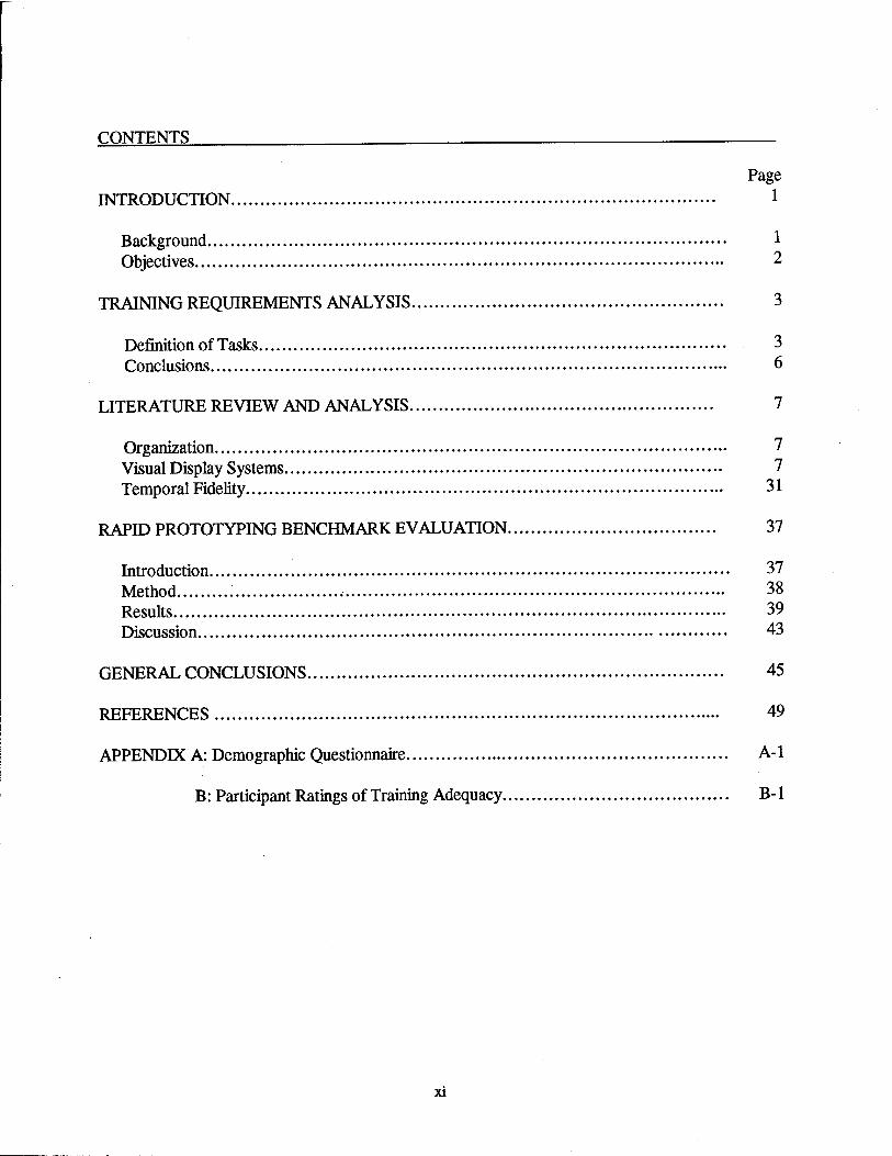
Page INTRODUCTION 1
Background • 1 Objectives 2
TRAINING REQUIREMENTS ANALYSIS 3
Definition of Tasks 3 Conclusions 6
LITERATURE REVIEW AND ANALYSIS 7
Organization 7 Visual Display Systems 7 Temporal Fidelity 31
RAPID PROTOTYPING BENCHMARK EVALUATION 37
Introduction 37 Method 38 Results 39 Discussion 43
GENERAL CONCLUSIONS 45
REFERENCES 49
APPENDDC A: Demographic Questionnaire A-l
B: Participant Ratings of Training Adequacy B-l
XI
CONTENTS (Continued)
Page
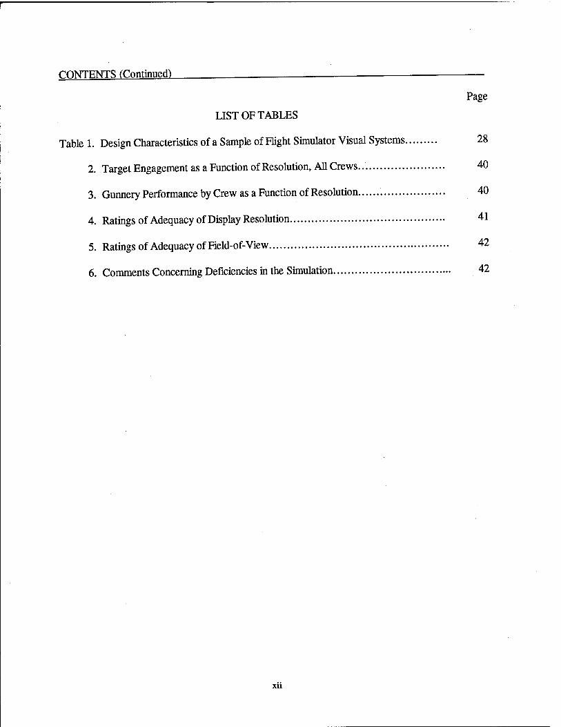
LIST OF TABLES
Table 1. Design Characteristics of a Sample of Flight Simulator Visual Systems 28
2. Target Engagement as a Function of Resolution, All Crews. 40
3. Gunnery Performance by Crew as a Function of Resolution 40
4. Ratings of Adequacy of Display Resolution 41
5. Ratings of Adequacy of Field-of-View 42
6. Comments Concerning Deficiencies in the Simulation 42
Xll
FIDELITY ANALYSIS FOR THE OH-58D KIOWA WARRIOR CREW TRAINER
Introduction
Background
The OH-58D Kiowa Warrior is an Army observation helicopter designed for use in close combat aerial reconnaissance, intelligence gathering, surveillance, and target acquisition. Unlike prior versions of the OH-58 helicopter, a variety of weapons can be mounted on and fired from the Kiowa Warrior. In addition, the aircraft is equipped with systems that greatly enhance its capability to perform missions under limited visibility conditions and at nap-of-the-earth (NOE) altitudes. A mast mounted sight (MMS) subsystem contains a television system (TVS), a thermal imaging system (TIS), a laser rangefmder/designator (LRF/D), and an optical boresight (OBS) unit.
The MMS enables the two-person crew to perform aeroscout missions at far greater standoff ranges and with far less exposure to enemy line-of-sight weapons than otherwise would be possible. The LRF/D can be used to designate a target for laser-seeking weapons and can accurately determine distance and direction from own aircraft to an intended target. The target information can be used for autonomous attack by the Kiowa Warrior or for target handover to an attack helicopter, a fixed wing tactical aircraft, or a field artillery unit. Supporting electronic systems provide for improved capabilities in communications, security, radar warning, navigation data, and aircraft identification.
Although the Kiowa Warrior's systems greatly increase the crewmembers' capability to perform their missions, the new systems also have increased training requirements. They must learn the functional characteristics of the new systems and how and when to use each system. There is anecdotal evidence that, despite the fact that many tasks have been semiautomated, the enhancements have resulted in a net increase in workload for both pilot and copilot-observer (CPO). As a consequence, crewmembers also must learn to cope with workload levels that are greater than those of previous OH-58 variants.
A host of factors makes it difficult to provide unit aviators with the training they need to sustain their skills. Most are the direct or indirect result of the dwindling resources available for training unit aviators. Others are the result of limited NOE flying areas and weapons firing areas. The following are among the most severe constraints on the sustainment training of field-unit aviators:
•
•
limited annual flying hours, limited ammunition available for training, limited NOE flying areas, limited firing ranges available for training, and

• lack of simulators and training devices available to field-unit aviators.
The Army has recognized the need for a crew trainer to augment the training of crew members who have completed the Kiowa Warrior Aircraft Qualification Training Course (AQC) and have been assigned to an operational field unit. Because many constraints prevent effective weapon systems training in the aircraft, it is essential that the crew trainer provide effective training on weapon systems tasks. Although training on weapon systems tasks is recognized as the greatest need, it is desirable that the crew trainer also be capable of training other tasks for which skills cannot be sustained effectively with units' training resources.
Declining resources have made it more important than ever to seek the optimal balance between cost and training effectiveness in specifying the functional and design requirements for the Kiowa Warrior Crew Trainer (KWCT). The optimal balance between cost and training effectiveness must be achieved by (a) determining the least fidelity in each design parameter that will fulfill the training requirement and (b) employing the least costly technology that will provide an adequate level of fidelity.
What is needed are functional and design requirements for a KWCT that provide effective sustainment training on weapon systems tasks and other tasks for which skills cannot be sustained with the training resources now available in operational field units. Because of the scarcity of resources for training device acquisition, it is essential that the fidelity level of the KWCT's components be no higher than the Army needs and can afford.
Objectives
General objective. The Program Manager-Kiowa Warrior requested that the Army Research Institute Rotary Wing Aviation Research Unit (ARI RWARU) perform a fidelity analysis to specify the functional and design requirements for a KWCT. Ideally, a program of research would be conducted to compile objective data on the relationship between training effectiveness and fidelity level for each component of a proposed KWCT. Time and resources required to conduct such a research program far exceeded those available for this project. For these reasons, it was necessary to conduct the fidelity analysis using information that can be gleaned from (a) an analytic study of training requirements, (b) a review of the open literature, and (c) an assessment of a benchmark crew trainer developed by ARI RWARU personnel. The specific objectives are listed and discussed below.
Specific objectives. A first step in any fidelity (requirements) analysis is to gain a clear understanding of the training requirements. When establishing training requirements for a device intended for sustainment training of unit aviators, it is not adequate to list the full complement of tasks required for combat. Skills on many tasks are sustained adequately by the routine mission flying each year, so little is gained from practicing these tasks in a training device. Hence, the objective of the training requirements analysis was to identify the tasks for which skills cannot be sustained adequately through routine mission flying.
The second specific objective of this project was to conduct a review of the literature and extract information that training system designers may find useful in making decisions about the most cost-effective level of fidelity for key design parameters. This literature review was based on the assumption that a flight simulator with a computer-generated visual display system1 will be required. It is recognized that another type of device (e.g., a procedures trainer with no visual system) may prove to be the most cost-effective crew trainer. The assumption that a flight simulator will be required simply ensured that the literature review encompassed all of the relevant literature for making the ultimate decision about the type of crew trainer that is the most cost and training effective.
A comprehensive review of the literature on visual display systems was made possible by the Joint Strike Fighter Visual Library (JSFVL) compiled for the Naval Air Systems Command. The JSFVL contains references and hard copies for nearly 600 recent documents that have a direct bearing on the design and use of flight simulator visual display systems. The products of this effort include a CD ROM that can be obtained from the Naval Air Systems Command (Naval Air Systems Command, 1996), a technical memorandum describing the project (Cross, 1996), and a hard copy library (one copy retained at Fort Rucker).
It is difficult to conceptualize the appearance of a visual display system and to estimate its training utility from a study of its design parameters (e.g., luminance, resolution, field-of-view [FOV]). Accordingly, a third specific objective was established, to develop and assess a "benchmark" KWCT testbed equipped with a relatively low fidelity (and low cost) visual display system. The original intent was to examine several levels of FOV and display resolution. Equipment limitations and the unavailability of an adequate number of experienced Kiowa Warrior crewmembers made it impossible to examine all levels of FOV and display resolution
Training Requirements Analysis
Definition of Tasks
Fidelity requirements for a training device vary widely as a function of the types of tasks to be trained . No documents were located that define the specific tasks to be trained in the KWCT. For this reason, an essential first step in the fidelity analysis was to formulate assumptions about the specific tasks for which skills must be sustained in the KWCT.
The primary requirement is for a device that will enable unit aviators to sustain their skills on tasks (mainly weapon systems tasks) for which skills degrade despite the hours spent each year flying the aircraft. Project personnel were unable to locate objective data with which to identify the tasks for which skills are (are not) sustained during the hours unit aviators spend flying the aircraft. A questionnaire survey was developed to collect data from unit aviators about the skills that degrade despite the hours spent flying. Because of limited time and support, the questionnaire was completed by only three experienced Army helicopter pilots, all of who are
1 The term "visual display system" is used throughout this report to refer to all components of a flight simulator out- the-window display system.
members of the ARIRWARU staff. Some of the conclusions drawn from the survey of ARI RWARU pilots were supported by opinions expressed by the Kiowa Warrior instructor pilots (IPs) who participated in the assessment of the benchmark crew trainer. Because so few pilots were surveyed, the following tentative conclusions about training-task requirements for a KWCT should be validated through a systematic survey of unit aviators.
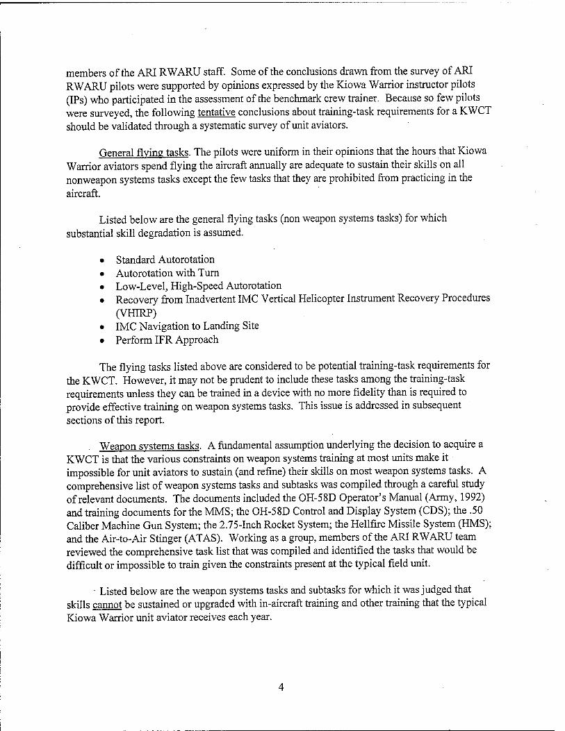
General flying tasks. The pilots were uniform in their opinions that the hours that Kiowa Warrior aviators spend flying the aircraft annually are adequate to sustain their skills on all nonweapon systems tasks except the few tasks that they are prohibited from practicing in the aircraft.
Listed below are the general flying tasks (non weapon systems tasks) for which substantial skill degradation is assumed.
• Standard Autorotation • Autorotation with Turn • Low-Level, High-Speed Autorotation • Recovery from Inadvertent IMC Vertical Helicopter Instrument Recovery Procedures
(VHIRP) • IMC Navigation to Landing Site • Perform IFR Approach
The flying tasks listed above are considered to be potential training-task requirements for the KWCT. However, it may not be prudent to include these tasks among the training-task requirements unless they can be trained in a device with no more fidelity than is required to provide effective training on weapon systems tasks. This issue is addressed in subsequent sections of this report.
Weapon systems tasks. A fundamental assumption underlying the decision to acquire a KWCT is that the various constraints on weapon systems training at most units make it impossible for unit aviators to sustain (and refine) their skills on most weapon systems tasks. A comprehensive list of weapon systems tasks and subtasks was compiled through a careful study of relevant documents. The documents included the OH-58D Operator's Manual (Army, 1992) and training documents for the MMS; the OH-58D Control and Display System (CDS); the .50 Caliber Machine Gun System; the 2.75-Inch Rocket System; the Hellfire Missile System (HMS); and the Air-to-Air Stinger (ATAS). Working as a group, members of the ARI RWARU team reviewed the comprehensive task list that was compiled and identified the tasks that would be difficult or impossible to train given the constraints present at the typical field unit.
• Listed below are the weapon systems tasks and subtasks for which it was judged that skills cannot be sustained or upgraded with in-aircraft training and other training that the typical Kiowa Warrior unit aviator receives each year.
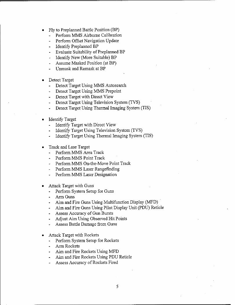
• Fly to Preplanned Battle Position (BP) - Perform MMS Airborne Calibration - Perform Offset Navigation Update - Identify Preplanned BP - Evaluate Suitability of Preplanned BP - Identify New (More Suitable) BP - Assume Masked Position (at BP) - Unmask and Remask at BP
• Detect Target - Detect Target Using MMS Autosearch - Detect Target Using MMS Prepoint - Detect Target with Direct View - Detect Target Using Television System (TVS) - Detect Target Using Thermal Imaging System (TIS)
• Identify Target - Identify Target with Direct View - Identify Target Using Television System (TVS) - Identify Target Using Thermal Imaging System (TIS)
• Track and Läse Target - Perform MMS Area Track - Perform MMS Point Track - Perform MMS On-the-Move Point Track - Perform MMS Laser Rangefinding - Perform MMS Laser Designation
• Attack Target with Guns - Perform System Setup for Guns - Arm Guns - Aim and Fire Guns Using Multifunction Display (MFD) - Aim and Fire Guns Using Pilot Display Unit (PDU) Reticle - Assess Accuracy of Gun Bursts - Adjust Aim Using Observed Hit Points - Assess Battle Damage from Guns
• Attack Target with Rockets - Perform System Setup for Rockets - Arm Rockets - Aim and Fire Rockets Using MFD - Aim and Fire Rockets Using PDU Reticle - Assess Accuracy of Rockets Fired

- Adjust Aim Using Observed Hit Points - Assess Battle Damage from Rockets
• Attack Target with Hellfire - Perform System Setup for Hellfire - Decide on and Select Most Suitable Launch Mode - Decide on and Select Most Suitable Delivery Mode - Arm Hellfire - Aim and Fire Hellfire (Using MFD) - Assess Accuracy of Hellfire (if Impact Point Visible) - Assess Battle Damage from Hellfire (if Impact Point Visible)
Collective tasks. The above list includes only crew tasks. It would be necessary to expand the list to include collective tasks if the intention is to network the KWCT with other simulators and use it to conduct collective training. A review of Army documents and open literature failed to reveal a clear description of tasks for which skills can be acquired and sustained only through collective training (Cross, Dohme, & Howse, 1997). The information available at this time suggests that the collective tasks for Kiowa Warrior crewmembers consist mainly of communications tasks. Specifically, collective operations will require the Kiowa Warrior crew to communicate with other helicopters in an attack company, the Aviation Tactical Operations Center (AVTOC), the tactical air and ground units that support the Kiowa Warrior's mission, and perhaps other battlefield elements as well.
If this conclusion is valid, a KWCT suitable for training weapon systems tasks would be suitable for training collective tasks if the device were equipped with the requisite communications capability, including full Airborne Target Handover System functionality. It follows that the level of fidelity required to train weapon systems tasks will be adequate for training collective tasks for all simulator components except the simulated communications systems.
Conclusions
Discussions among ARI RWARU members and IPs in the assessment of the benchmark KWCT led to the following conclusions about conditions in which the tasks listed above should be trained. First, it was concluded that the KWCT should be capable of training these tasks under the full range of visibility conditions. In addition to training the tasks under both day and night illumination conditions with good visibility, the KWCT should be capable of training the tasks (during both day and night light conditions) with visibility obscured by precipitation, fog, smoke, or a combination of these. It is important that the simulated illumination and obscurant effects influence the visibility for both the out-the-window and sensor displays (TV and TIS). For training on the HMS, it is particularly important to have the capability to simulate a cloud layer that is low enough to influence the crews' choice of delivery mode.
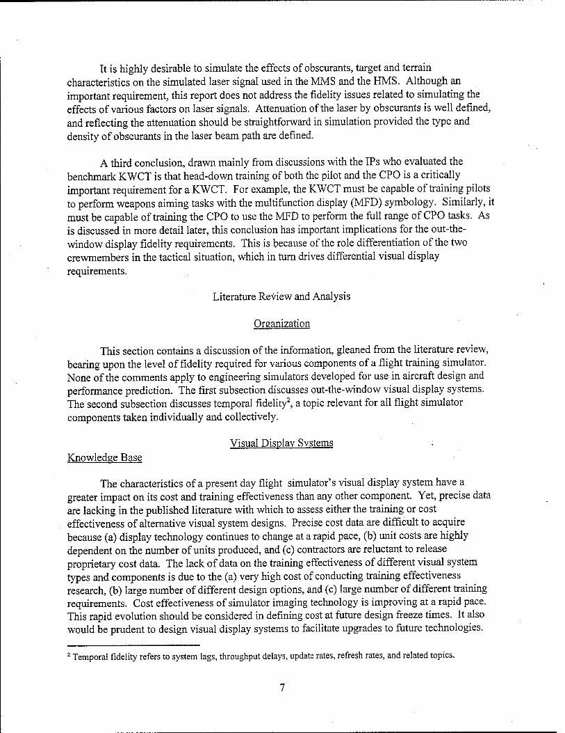
It is highly desirable to simulate the effects of obscurants, target and terrain characteristics on the simulated laser signal used in the MMS and the HMS. Although an important requirement, this report does not address the fidelity issues related to simulating the effects of various factors on laser signals. Attenuation of the laser by obscurants is well defined, and reflecting the attenuation should be straightforward in simulation provided the type and density of obscurants in the laser beam path are defined.
A third conclusion, drawn mainly from discussions with the IPs who evaluated the benchmark KWCT is that head-down training of both the pilot and the CPO is a critically important requirement for a KWCT. For example, the KWCT must be capable of training pilots to perform weapons aiming tasks with the multifunction display (MFD) symbology. Similarly, it must be capable of training the CPO to use the MFD to perform the full range of CPO tasks. As is discussed in more detail later, this conclusion has important implications for the out-the- window display fidelity requirements. This is because of the role differentiation of the two crewmembers in the tactical situation, which in turn drives differential visual display requirements.
Literature Review and Analysis
Organization
This section contains a discussion of the information, gleaned from the literature review, bearing upon the level of fidelity required for various components of a flight training simulator. None of the comments apply to engineering simulators developed for use in aircraft design and performance prediction. The first subsection discusses out-the-window visual display systems. The second subsection discusses temporal fidelity2, a topic relevant for all flight simulator components taken individually and collectively.
Visual Display Systems Knowledge Base
The characteristics of a present day flight simulator's visual display system have a greater impact on its cost and training effectiveness than any other component. Yet, precise data are lacking in the published literature with which to assess either the training or cost effectiveness of alternative visual system designs. Precise cost data are difficult to acquire because (a) display technology continues to change at a rapid pace, (b) unit costs are highly dependent on the number of units produced, and (c) contractors are reluctant to release proprietary cost data. The lack of data on the training effectiveness of different visual system types and components is due to the (a) very high cost of conducting training effectiveness research, (b) large number of different design options, and (c) large number of different training requirements. Cost effectiveness of simulator imaging technology is improving at a rapid pace. This rapid evolution should be considered in defining cost at future design freeze times. It also would be prudent to design visual display systems to facilitate upgrades to future technologies.
2 Temporal fidelity refers to system lags, throughput delays, update rates, refresh rates, and related topics.
PC-hosted and minicomputer-based visual display systems now provide substantial imaging capabilities that may satisfy KWCT requirements at a very favorable cost. Although precise cost and training effectiveness data are lacking, the literature on visual display systems contains much information that training system acquisition personnel should find helpful in making tradeoff decisions. The findings judged to be most relevant for the KWCT are presented in this section.
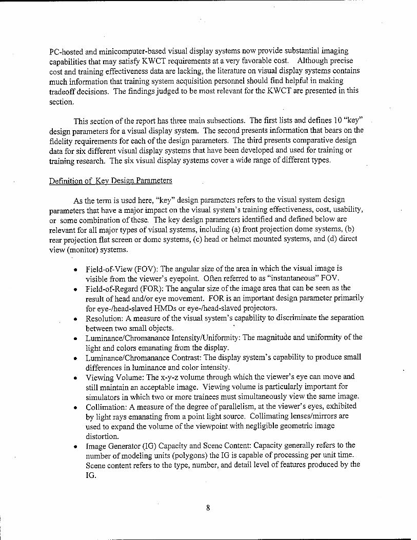
This section of the report has three main subsections. The first lists and defines 10 "key" design parameters for a visual display system. The second presents information that bears on the fidelity requirements for each of the design parameters. The third presents comparative design data for six different visual display systems that have been developed and used for training or training research. The six visual display systems cover a wide range of different types.
Definition of Key Design Parameters
As the term is used here, "key" design parameters refers to the visual system design parameters that have a major impact on the visual system's training effectiveness, cost, usability, or some combination of these. The key design parameters identified and defined below are relevant for all major types of visual systems, including (a) front projection dome systems, (b) rear projection flat screen or dome systems, (c) head or helmet mounted systems, and (d) direct view (monitor) systems.
• Field-of-View (FOV): The angular size of the area in which the visual image is visible from the viewer's eyepoint. Often referred to as "instantaneous" FOV.
• Field-of-Regard (FOR): The angular size of the image area that can be seen as the result of head and/or eye movement. FOR is an important design parameter primarily for eye-/head-slaved HMDs or eye-/head-slaved projectors.
• Resolution: A measure of the visual system's capability to discriminate the separation between two small objects.
• Luminance/Chromanance Intensity/Uniformity: The magnitude and uniformity of the light and colors emanating from the display.
• Luminance/Chromanance Contrast: The display system's capability to produce small differences in luminance and color intensity.
• Viewing Volume: The x-y-z volume through which the viewer's eye can move and still maintain an acceptable image. Viewing volume is particularly important for simulators in which two or more trainees must simultaneously view the same image.
• Collimation: A measure of the degree of parallelism, at the viewer's eyes, exhibited by light rays emanating from a point light source. Collimating lenses/mirrors are used to expand the volume of the viewpoint with negligible geometric image distortion.
• Image Generator (IG) Capacity and Scene Content: Capacity generally refers to the number of modeling units (polygons) the IG is capable of processing per unit time. Scene content refers to the type, number, and detail level of features produced by the IG.
• Image Aliasing: Undesirable visual artifacts that result from the temporal or spatial sampling of the displayed image produced by an IG.
• Space Requirement and Transportability: The size of the area required to house a visual system.
It is important to acknowledge the existence of other design parameters unique to a particular type of visual display system. Helmet comfort and ease of calibration are important design parameters for HMDs (Silverman & Spiker, 1996). Screen characteristics are important for all projection systems, as are ease and accuracy of edge, spatial, intensity and color matching for multichannel continuous image projector systems. Ease and quality of image blending are critical for visual systems that have a high-resolution "area-of-interest" image superimposed on a lower resolution background image.
A host of factors influence the ease and cost of using and maintaining a visual display system. Automatic adjustment, component reliability, number and cost of consumable parts, operating costs, safety, user interface, and requirement for climate control are examples of other factors one must consider in selecting the most cost-effective visual display system. All of these other design parameters are important and must be considered in the final selection of a visual display system An in-depth discussion of the key design parameters follows.
Field-of-View
Overview of findings . FOV is the design parameter that usually has the greatest influence on a visual display system's cost and training effectiveness. Current IG and display technologies can provide about 2 arc min resolution pixels over a line 60° wide, using high end technology. FOV and resolution are among the most common tradeoffs in simulator design. Mid-level technology should provide at least 3 arc min over the same lateral FOV. Most simulator designs add IG and display channels to extend the FOV beyond 60°. In addition to the cost of additional display and IG channels, increasing FOV increases the space required to accommodate every type of visual system except some types of helmet mounted display (HMD) systems.
The enormous amount of resources expended to increase the size of simulators' instantaneous FOV is compelling evidence that both display manufacturers and their customers believe a wide FOV is essential for many training applications. Most of the recent innovations in flight simulator display technology have been motivated by the need to increase FOV while keeping display resolution and luminance at acceptable levels. The literature review revealed only seven research studies that investigated the relationship between FOV and training effectiveness. Three studies showed that performance and/or training transfer was better with a wide than a narrow FOV (Lintern, Taylor, Koonce, & Talleur, 1993; Taylor et al., 1993; Westra & Lintern, 1985; Westra, Sheppard, Jones & Hettinger, 1987). The remaining studies found that FOV had no effect on training transfer (Lintern, Sheppard, Parker, Yates, & Nolan, 1989; Nataupsky, Waag, Weyer, McFadden, & McDowell, 1979; Westra et al., 1986) or only a small, temporary effect (Westra, 1982). The piloting tasks being performed varied between studies,
making comparability difficult. It is not inconceivable that some tasks are'more dependent on the use of peripheral cues than are others.
A far larger number of studies have investigated the relationship between FOV and (a) pilots' performance of flying tasks in a flight simulator or (b) pilots' ratings of the adequacy of a flight simulator's FOV. (Such studies are more numerous because they are far less time and resource intensive than transfer-of-training studies.) This body of literature supports the following conclusions.
• No improvement in pitch and roll control results from increasing horizontal FOV beyond about 60°(Kenyon & Kneller, 1992; Kenyon & Kneller, 1993; McMillan, Cress, & Middendorf, 1990).
• Performance on takeoff, landing, and straight-and-level flight is not improved by increasing horizontal FOV beyond about 60° (Batson, Harris, & Houck, 1992).
• Although a task can be performed adequately with a FOV that is considerably less than that available in the aircraft, the limited FOV may cause pilots to adopt performance strategies that differ from those used in the aircraft (Dixon & Curry, 1987; Dixon, Martin, & Krueger, 1990; Dixon & Curry, 1990).
• The optimal FOV for an area-of-interest (AOI) inset depends on the task being performed, but horizontal FOV of 30° is near optimal for most tasks (Warner, Serfoss, &Hubbard, 1993).
Limitations. The research conducted to date has three important shortcomings. First, most recent FOV research has investigated only fixed wing tasks. The only recent research on helicopter task performance investigated FOV requirements only for sensor displays (Grunwald & Kohn, 1994; Grunwald, Kohn, & Merhav, 1991). Two studies, conducted in the early 1960s, investigated the relationship between FOV and performance on a helicopter hovering task and are not cited because methodological problems invalidated the results.
Second, no studies have investigated the effects of vertical FOV on training effectiveness or in-simulator training in a systematic manner. Experts agree that vertical FOVs larger than those currently extant are needed for most fixed wing and rotary wing simulators, but especially for the latter (Bridgwater, 1992). However, the literature review revealed only one visual system that was designed specifically for use in a helicopter simulator and that provides a large vertical FOV (100°) (Poulinquen, 1994). This shortcoming is particularly important for helicopter simulators because a large vertical FOV is desirable for performing many tasks required for weapon systems training (e.g., hovering, NOE flight, masking and unmasking).
Third, there are no studies that have investigated the FOV required for training two crewmembers seated side by side. The visual systems designed for side-by-side seating reflect the designers' assumption that both crewmembers required the same FOV. This is probably not a valid assumption for helicopter simulators, but no objective data are available to support this belief.
10
Implications. Research findings support the conclusion that many flying tasks can be trained in a helicopter simulator that has a horizontal FOV as narrow as about 60°. Data on military helicopter FOV requirements are sparse. One study (Wright, Phillips, Simmons, Melton, & Kimball, 1981) investigated the relationship between pilot gaze point and the demands of the maneuver tasks performed. Results showed that gaze points were generally fixed straight ahead for hovering tasks, but wider for tasks like autorotation. The tasks that can be trained with a narrow FOV (e.g., takeoffs, landings, straight and level flight) are not the tasks that need to be trained in the KWCT. Equally important, there are no data with which to estimate the FOV required to support the training of crewmembers that are seated side-by-side.
Existing research on FOV requires considerable judgment to apply to FOV requirements for the KWCT. It is assumed that the time and resources needed to conduct systematic research on FOV are not available. If this is correct, FOV decisions must be based on the (a) tasks that must be trained in the KWCT, (b) FOV available on other helicopter simulators, and (c) existing research.
The AH-64 Combat Mission Simulator (CMS) is comparable to the KWCT in terms of training requirements. The AH-64 CMS pilot station has a horizontal FOV of 102° and a vertical FOV that varies from 40° (front window) to 48°(side window). (The AH-64 CMS visual system consists of a front display with a 30°H x 40°V FOV and two side windows, each with a 36°H x 48°V FOV.) A reasonable assumption is that a similar horizontal and vertical FOV is about the minimum that would support the training of Kiowa Warrior pilots. There is no apparent reason why a FOV that is adequate for training Kiowa Warrior pilots would not be adequate for training CPOs. However, it may be possible to accomplish effective CPO training with a smaller FOV than is needed to pilot the aircraft.
There are reasons to believe that a wider FOV than is available on the AH-64 CMS may be desirable. Anecdotal information from experienced AH-64 pilots suggests that a wider horizontal FOV would (a) facilitate performance on tasks such as NOE flight, masking/unmasking, and formation flight, and (b) facilitate situational awareness by making it easier to keep track of other friendly aircraft during collective training exercises. A final consideration is. that using a simulator FOV that is considerably less than the FOV in the parent aircraft may cause trainees to adopt response strategies that differ from those used in the aircraft (Dixon & Curry, 1987; Dixon et al, 1990; Dixon & Curry, 1990).
Research literature concerning vertical FOV requirements indicates that increasing it should facilitate flight control in hovering tasks (Wright, et al., 1981). Some innovative efforts to increase vertical FOV have been motivated by the belief that on most simulators it is clearly inadequate (40° to 50°), especially for helicopter simulators (Bridgwater, 1992). Research on image change geometry (Wright, 1989) provides direct logical evidence as to vertical FOV requirements. An unpublished analysis by Wright indicates that vertical motions will overwhelm the perception of motions along the velocity vector over flat surfaces, until downlooking angles reach 60° to 90°.
11
Field-of-Regard
The FOR design parameter is relevant only for head-slaved visual systems in which the instantaneous FOV varies as a function of head position. A very large horizontal and vertical FOR (at least 300°) is required to support performance of air-to-air combat tasks (Barrette et al., 1990; Kruk & Runnings, 1989). A head-slaved system is not recommended for a visual system that is viewed simultaneously by two crewmembers. Furthermore, a head-slaved visual system is appropriate for a flight simulator only if the parent aircraft affords the pilot a very wide FOV. Because a head-slaved visual system is considered inappropriate for the KWCT, the research and development literature on FOR is not reviewed here.
Visual Display System Resolution
Overview of findings. Resolution is widely recognized as a major parameter affecting both training effectiveness and cost (Lyon & Black, 1996). Because of the exponential relationship between cost and resolution, it is critically important to determine how much resolution is needed to accomplish effective training on various tasks. No systematic research has been conducted to determine the relationship between resolution and training effectiveness for a representative sample of flying tasks. As a consequence, it is necessary to use other information in specifying resolution requirements for a visual system. Before discussing this information, however, it is important to define the terminology that has been used to quantify display resolution.
Definition of terms. Resolution is a measure of a visual display system's ability to separate two small objects, such as two black lines that are separated by a white space. Every component of a visual system (IG, projector or display, lenses, etc.) contributes to the system resolution, so system resolution must be no better than the components with the poorest resolution. With contemporary visual systems that receive their input from an IG, resolution is measured by programming the IG to input a test pattern. The test pattern consists of a series of black lines that are separated by white spaces. (The widths of the black lines are always the same as the width of the white spaces.) The luminous contrast between the black lines and white spaces can be measured at the display (output) and Equation 1 can be used to compute contrast modulation.
Contrast Modulation (Cm) = (L - D)/(L + D) (Equation 1)
Where: L = white field luminance D = dark field luminance
When the space between black lines is very large, Cm = 100%, and as the space between the lines becomes progressively less, Cm approaches 0%. Plotting Cm as a function of the angular separation between the black lines yields a Modulation Transfer Function (MTF) for the visual system. The most widely accepted metric for display resolution is the angle subtended by a black line and a white space at the point on the MTF at which Cm = 10%. Display resolution is expressed in terms of arc-minutes per optical line pair (OLP) at 10% contrast modulation.
12
Addressability often is mistakenly used as a metric of display resolution. Addressability is expressed in one of two ways. One way is to cite the number of addressable lines (1,000 by 1,000 line display) or the number of addressable pixels on a display (1,000,000 pixel display). A second way is to cite the visual angle subtended by an addressable line (arc-minutes per line or line pair) or an addressable pixel (arc-minutes per pixel). Display resolution is certainly influenced by the number and size of addressable elements. However, because every visual display system component modulates (reduces) the quality of the input image, resolution cannot equal addressability.
There are four basic ways to increase display resolution: increase the number of addressable pixels on the display, increase the quality of the optics, decrease the FOV of the display channels, and reduce or eliminate antialiasing. Increasing the number of addressable pixels requires a higher capacity (more costly) IG to create the imagery at an acceptable update rate. Increasing the quality of the optics often results in an exponential increase in cost. Decreasing the FOV of a display channel results in an increase in the number (and cost) of display channels and IG channels required to provide an acceptable FOV. Eliminating or reducing antialiasing results in undesirable and distracting image artifacts. In short, there is no inexpensive way to produce a visual display system that has both high resolution and a wide FOV.
Resolution required for target detection and identification. The quest for ever higher resolution visual display systems has been driven mainly by the desire to produce systems that will support realistic training on target detection and recognition tasks. It has been assumed that such training is realistic only if the resolution is high enough to enable trainees to detect and identify targets at realistic standoff ranges. To a lesser extent, the quest for higher resolution has been motivated by the assumption that relatively high-resolution visual display systems are needed to support training on tasks other than target detection and identification. These are tasks that require accurate judgments of distance and lateral clearance. Examples include takeoffs, landings, low altitude flight, formation flight, and hovering flight.
Resolution requirements are higher for target detection and identification than any other task, so it is worthwhile to determine the visual display system required, at realistic standoff ranges. This is not a simple task. The range at which a target can be detected and identified on an imaging system has been shown to be a function of many different factors (Ericksen, 1978; Kincade, Silbernagel, O'Hara, Shirkey, & Cassidy, 1978; Scanlan, 1976; Silbernagel, 1982). Listed below are the most important factors:
• number of scan lines3 that overlay (cross over) the target image;
3 A scan line is a single continuous narrow strip of the picture area containing luminous variations formed by one horizontal sweep of a scanning spot on an imaging display. Scan line is not to be confused with a resolution pattern line, which is a line on a periodic bar test pattern used to measure resolution. Scan lines are the lines written on the display; resolution lines are on a test pattern generated by the IG'.
13
• target characteristics (e.g., size, shape, luminance, color, presence of targets with similar shapes);
• characteristics of the background against which a target is viewed (e.g., complexity, clutter, luminance, color);
• size of the area to be searched; • display luminance and FOV; and • operator factors (training, experience, fatigue, and stress).
The number of scan lines that overlay the target is one of the most important factors for estimating the resolution needed to support target detection and identification. A substantial amount of research was conducted in the late 1960s and early 1970s to determine the number of lines that must overlay a target in order for it to be detected and be identified with a high probability of success. This research has been reviewed and summarized by Erickson (1978), who conducted much of the research. The research findings of particular relevance for the KWCT are summarized below:
• One scan line is required to detect a small, high contrast target (e.g., a hot target on cold FLIR background);
• Three scan lines are required to detect a small, low contrast target; • Ten scan lines are required to identify a military ground vehicle, a building, a bridge;
and • Twelve scan lines are required to identify a military aircraft.
The "scan lines required" refers to the number of scan lines that must overlay the target in order for it to be detected or identified. It is important to emphasize that the scan line requirements cited above represent best case rules-of-thumb. The number of scan lines required to detect and identify targets could be increased by an order of magnitude by any one of a host of factors (e.g., large search area, nonoptimal aspect angle, highly cluttered background, fatigued operator).
Resolution requirements for a visual display system can be specified in terms of the (a) size of target that must be detected/identified, (b) range at which it must be detected/identified, and (c) number of scan lines that must overlay the target in order for it to be detected/identified (Erickson's data). For example, assume that a display resolution is required that will enable a tank (3 m high) to be identified at a range of 1,000 m. According to Erickson's data, 10 scan lines must overlay a 3 m high tank in order for it to be identified, so the display must be capable of portraying 10 addressable scan lines in the angle subtended by the tank. In this example, the tank subtends a visual angle of 10.3 minutes of arc.4 To meet this requirement, the display must have a resolution of about 1 arc-minute per addressable line. To achieve this resolution, the FOV for a 1,000-line display would have to be about 17°; a 120° FOV at this resolution would require seven 1,000-line display channels. It is worth noting that this derivation of the resolution required for target detection and identification corresponds closely with the findings of recent
4 The angle subtended by a 3 m high tank at 1,000 m = 2 arc/tan (1.5 m/1,000 m) = 10.3 minutes of arc.
14
research to assess target detection and identification ranges with a flight simulator visual system (Barrette et al, 1990).
It has been estimated that, for most raster systems, resolvable lines are about 0.7 of addressable lines (Bess, 1989; Hsu, 1986). Furthermore, 1,000 m is less than a realistic standoff range for identifying a tank. For these reasons, the resolution requirements imposed by realistic target identification are somewhat more severe than is indicated by the above computations.
Antialiasing effects on resolution. The primary techniques used in IGs to reduce perception of aliasing in digital image structure result in substantial blurring of the image. This blurring reduces resolution. The above discussion on resolution in target acquisition is based on video displays without antialiasing. The consequence of antialiasing forces consideration of the degree of blurring and its effect on target acquisition. For most targets and backgrounds, the effect will be a major reduction (by factors of approximately two to five) in the range of target detection, recognition, identification, and orientation awareness. For very high target to background contrast ratios, antialiasing can increase detection ranges by increasing the size of the target "spot." Aliasing effects in perception should not occur if the display resolution is 50% or less of eye resolution (the Nyquist frequency) and may not be noticeable at 100% of eye resolution.
A few antialiasing techniques, not currently used in IG display systems, could improve resolution for target acquisition. "Flat field" display adjustment (Schade, 1973) is one way to improve resolution across the display lines (usually vertical resolution, which is the critical axis for target acquisition and terrain surface apperception). Flat field adjustment involves spreading a CRT beam so that the black spaces between the video lines disappear. If conventional CRT displays are used, flat field adjustment can provide improvement in perceived display resolution. It may not, however, apply to shadow mask color monitor displays or LCD's, which use individual display elements or phosphor points for pixels (at least without modification).
Area-of-interest (API) insets. The high cost of producing a high resolution, wide FOV display has led to the development of head- and/or eye-slaved, high-resolution AOI insets, which overlay a lower resolution background image. Designers have successfully incorporated AOI insets into the design of visual systems developed for fixed wing aircraft simulators, including both HMDs and large dome displays. Although the use of an AOI inset is a cost-effective solution for some training applications, such systems are not inexpensive. Among the items that contribute to the high cost of AOI inset systems are: (a) equipment required to track the head and/or eye, (b) additional display channels required to display the AOI inset, and (c) additional IG capacity to produce the AOI image and to blend its edges with background imagery.
At present, it may be prohibitively expensive to use AOI insets in a KWCT. No evidence is available on the feasibility of using AOI insets for one or both crewmembers who are seated side-by-side and view the same display. Even so, the use of AOI insets remains the only feasible method for providing the resolution that is needed to detect and identify targets at realistic standoff ranges. With the rapid evolution of the technology, AOI insets should not be ruled out; recent advances in digital technology could bring down the cost of AOI insets.
15
Resolution requirements for other flying tasks. The simulation literature contains little information useful for specifying the resolution required for training tasks other than target detection and identification. Visual display system design practices reflect the belief that other tasks require far less resolution than target detection and identification. Very little empirical data are available to support this belief. The only empirical data come from a small number of studies that have investigated the relationship between resolution and in-simulator performance of a small number of flying tasks. The results of these studies are summarized below.
• Performance of low-level flight in a fixed wing simulator was no better when performed with a high-resolution AOI inset (resolution = 1.5 arc-minutes per pixel) than with only the lower resolution background image inset (resolution = 5.0 arc- minutes per pixel) (Barrette et al, 1990; Kruk & Runnings, 1989).
• Resolution of 5 arc-minutes per line and 11 arc-minutes per line resulted in the same low-level flight performance in a fixed wing simulator (Browder & Chambers, 1988).
• Lateral error in performing flares and landings in a fixed wing simulator was poorer with a resolution of 4.8 arc-minutes per pixel than with a resolution of 2.4 arc- minutes per pixel or 0.6 arc-minutes per pixel. However, performance did not differ for the latter two resolution levels (Batson et al., 1992).
Inconsistent metrics for resolution. The only other information available on the resolution required for training on tasks other than target detection and identification comes from the opinions of accepted experts and from information about the resolution of contemporary simulators. One expert, for example, suggested that a resolution of about 4 arc-minutes is adequate for most tasks other than target detection/identification (Padmos & Milders, 1992), and cites data or rationale to support his opinion. A comparison of the resolution of contemporary flight simulators is difficult because of the inconsistency in the methods used to quantify resolution and, in most cases, a failure to state the precise method that was used. When resolution in arc-minutes per optical line pair was reported, the resolution measures5 varied from 5.8 (Barber, Burbidge, & Roberts, 1987) to 20.7 (Larsen & Gruendell, 1994). When resolution in arc-minutes per pixel was reported, the resolution measures varied from 2.3 (Naval Training Systems Center, 1991) to 6.0 (Hughes, 1992). This lack of a consistent benchmark is an impediment to the important guidance that could be gleaned from this area of research.
Display quality measures. Much research has been conducted on methods and metrics for assessing the quality of a displayed image (Beaton & Farley, 1991; Evans, 1990; Evans, 1993; Jorna, 1993; Verona, 1992). Most of the metrics are variations of the MTF that have been derived to correlate more highly with observers' quality ratings than the basic MTF metric. Two important conclusions are reported in an excellent review of research on display quality metrics (Gallimore, 1991). First, quality metrics have been developed that are effective in predicting observers' ratings of image quality. Second, there are very little data showing that any of these
5 For systems equipped with an AOI inset, the resolution measures cited in this paragraph are for the background image.
16
metrics are effective predictors of visual task performance. Gallimore (1991) speculates that display quality metrics may not be useful predictors of visual task performance.
There are no reasons to doubt the widespread belief that display quality influences user acceptance of a visual display system. There is no basis for establishing display quality as a requirement for the KWCT (or for any other device). Before display quality can be included in a visual system requirements document, there must be compelling evidence that it contributes to training effectiveness. A reasonably high level of display quality is ensured by requirements established for design parameters such as FOV, resolution, luminance/chromanance, contrast, antialiasing, IG characteristics, etc.
Implications. One important implication of the literature review on resolution is that it would be prohibitively costly to provide a visual display system with both an adequate FOV and a uniform level of resolution that would support target detection and identification at realistic standoff ranges. If such a capability is considered essential, a study should be conducted to assess the feasibility and cost of using a high-resolution AOI inset for one or both crewmembers. A potential solution to this problem is the use of laser projector displays. Although the literature contains little information about the capabilities, cost, and safety of laser projectors, the information available suggests that laser projectors are under development that will provide a bright, high-resolution image over a wide FOV (Peppier & Gainer, 1993). These potential benefits must be traded off against substantial IG requirements, however.
A case can be made that the Kiowa Warrior visual display system does not need the capability to portray visible targets at realistic standoff ranges. The Kiowa Warrior MMS and weapon control systems were designed to enable the crew to acquire targets that are not visible out-the-window because of darkness, atmospheric attenuation, obscurants, range, or some combination of these. Hence, training crewmembers to acquire and attack targets with the TVS and TIS must be considered an important training requirement. Because of their magnification capabilities, a very high level of resolution is not required to acquire and attack targets with the TVS and TIS.
The literature contains virtually no data with which to estimate the display resolution that is required to support training on tasks other than target detection and identification. One alternative for establishing resolution requirements for these other tasks is to establish the level of resolution that contemporary flight simulators are capable of producing. Based on the information available, representative values would be about 8 arc-minutes per optical line pair and 10% MTF or 5 arc-minutes per pixel (addressability measure). Although clearly the most expedient, this approach runs the risk of buying too much or too little resolution; it also may lead to a nonoptimal tradeoff between resolution and FOV.
A second approach is to design and conduct a survey of experienced aviators to assess their opinions about the suitability of the resolution levels of production Army flight simulators for training each of a representative sample of tasks. An empirical study of the relationship between resolution and in-simulator performance would be far better, but is not recommended because of the limited time and resources available.
17
Visual Display System Luminance and Contrast
Overview of findings. A consideration of the luminance and contrast6 requirements for a visual system requires an understanding of three characteristics of the human eye. First, as is well known by aviators, the human eye is capable of adapting to an enormous range of luminous flux. What is less well known is that, because of the eye's adaptation capability, a very low level of brightness (about 1 fL7) is adequate to maintain the illusion of a daylight scene in a flight simulator visual system (Advisory Group for Aerospace Research and Development [AGARD], 1981). A second important characteristic of the human eye is that the eye's spatial acuity (ability to discriminate small details) increases as a function of luminance to a maximum acuity at about 100 fL (Kaufman, 1966). That is, visual acuity does not increase as luminance is increased beyond 100 fL. A third important characteristic is that the eye's sensitivity to flicker is higher at high luminance levels. So, to avoid flicker, it is necessary to have a higher refresh rate at a high luminance level than at a low luminance level.
As was true for resolution, the requirement for luminance depends on the task being trained. A high luminance level is necessitated to detect and identify targets (or navigation checkpoints) at realistic standoff ranges. Because the eye's spatial acuity is related to luminance level, the full advantages of a high-resolution visual system are not realized unless luminance level is relatively high. For example, it has been shown that a 15 fL luminance level was too low to realize the full benefits of a high-resolution AOI inset in performing a target identification task (Barrette et al., 1990). That is, the target identification range was substantially less for predictions based only on the AOI resolution.
A requirement of a luminance level of 100 fL would eliminate any risk that luminance level is too low to maximize target detection and the identification range. However, such a high level of luminance is probably not feasible because of cost constraints. There is some evidence from laboratory research that the loss in target detection/identification range is minimal as luminance level is decreased from 100 fL to 50 fL (Harris, 1974). Based on the information available, it is concluded that 50 fL should be considered the minimal luminance that is required to support training on target detection/identification.
The luminance level required to train target detection and identification tasks is certain to be far higher than that required to train other tasks. AGARD (1981) and the Federal Aviation Administration (FAA, 1980) consider a luminance of about 6 fL to be adequate for training most tasks. Indeed, many contemporary flight simulators operate with an average luminance requirement of 6.0 fL or less (see Table 1 in next section).
There are several reasons to question the adequacy of a luminance of 6.0 fL for training tasks other than target detection/identification in the KWCT. First, the conclusion that 6.0 fL is
6 Unless stated otherwise, the term "contrast" refers to luminance contrast. 7 Two units of luminance are used in this report: foot lambert (fL) and candelas per square meter (cd/M2). Conversion from one unit to the other can be accomplished with the conversion factor: 1 cd/M2 = 0.292 fL.
18

an adequate luminance level does not appear to be based on empirical research. Second, it appears that the adequacy of 6.0 fL is relative to the needs of fixed wing simulators (commercial aircraft and military aircraft). Third, it is probable that higher luminance is needed in a helicopter to enable pilots to make the accurate judgments of distance and clearance that are required to operate close to the ground.
For the above reasons, 6.0 fL is considered the absolute minimum luminance requirement for training tasks other than target detection/identification in the KWCT. A luminance of about 20 fL should be adequate to eliminate any risk that training effectiveness would be compromised by inadequate luminance. In addition, most display light input sources degrade over time. For example, a system designed to provide 10 fL may average 6 fL over the course of its operating life.
Luminance contrast usually is expressed as the ratio of the maximum luminance divided by the minimum luminance. The minimum luminance never approaches zero because of noise in the visual system and reflected light. For these reasons, it is not possible to achieve a very high contrast ratio (i.e., 1000:1) with a low maximum luminance level. Or, stated differently, reducing the maximum luminance level reduces the contrast range.
A report by AGARD states that a contrast ratio of 1000:1 is ideal (AGARD, 1981), but few visual system designers believe that such a high contrast ratio is either practical or necessary (Bess, 1989). Padmos & Milders (1992) stated that a contrast ratio between 10:1 and 25:1 is adequate for most purposes. This belief is supported by the fact that the contrast ratio for most contemporary visual systems is about 25:1; a few are capable of a contrast ratio of 50:1 or higher. Visual systems with a luminance of only 6.0 fL are capable of producing a ratio of at least 25:1.
Implications. It seems reasonable to conclude that a luminance requirement of no less than 50 fL be adopted if the KWCT is to be used to train tasks that require trainees to detect/identify targets at a realistic standoff range. Otherwise, a luminance requirement between 6.0 fL (high risk) and 20 fL (low risk) should be adopted. A contrast ratio no less than 25:1 should be required. Although a higher contrast ratio would be required to support target detection/identification at realistic standoff ranges, the higher luminance level required for discriminating small objects at great distances (at least 50.0 fL) should ensure a sufficiently high contrast ratio.
Visual Display System Viewing Volume and Collimation
Overview of findings. The requirement for a visual display system that provides cross- cockpit viewing by two crewmembers creates a host of problems for designers. The problems stem mainly from the fact that the displayed image of a distant object can be corrected for only one eyepoint, referred to as the design eyepoint. Parallax8 errors, image size distortions, and
8 Parallax is the apparent change in direction from the viewer's eye to an object that results from a lateral change in the observer's position. For a fixed change in lateral position, the apparent change in direction is far greater for close objects than for distant objects.
19
luminance losses occur when the image is viewed from any point other than the design eyepoint. There is evidence that viewing a visual system display from a position other than the design eyepoint increases the incidence of simulator sickness (Kennedy & Lilienthal, 1994; Kennedy & Lilienthal, 1995). The magnitude of parallax errors and size distortions (and probably other problems as well) varies as a function of the distance between actual viewing point and design eyepoint.
Possible solutions. Three potential approaches are available for solving the above problems. One approach is to tolerate the problem. If the difference between actual and design eyepoint is small, parallax errors and size distortions may be below the perceptual threshold. A second approach is to increase the distance between viewer and display. The third approach is to employ collimating mirrors or lenses. The latter two approaches serve to increase the visual system's viewing volume, that is, the volume of space in which the trainee maintains an acceptable image.
Little research has been conducted to assess the size of the difference between the actual viewing point and the design eyepoint that is tolerable (with respect to training effectiveness and/or pilot acceptance). One study investigated the feasibility of using a large dome (7.3 m [24 ft] diameter) visual display system for side-by-side seating (Martin, 1991). In the cockpit used for that study, the pilot's and copilot's head positions were separated by 1.06 m (3.5 ft). This was found to be totally unacceptable to a crewmember when the design eyepoint was set to the head position of the other crewmember. The system was found "marginally acceptable" when the design eyepoint was set to a point halfway between the crewmembers' head positions. No performance data were collected, so the meaning of "marginally unacceptable" is not clear. An important fact is that a distance as small as 0.53 m (1.75 ft) between actual and design eyepoint is easily perceived , and found troubling, by crewmembers.
The second approach, increasing the distance between the viewer and the display surface, has been found effective for visual display systems developed for large surface-ship simulators but not for flight simulators. The reason is that the distances must be very large to increase viewing volume substantially. This fact is illustrated by a simple calculation using Equation 2 , which yields the required viewing distance as a function of the desired viewing volume and yields the angular size of the parallax error that is permissible (Padmos & Milders, 1992).
D = (V) (57/oc) (Equation 2)
Where: D = viewing distance V = size of desired viewing volume a = permissible parallax error
Assuming that a 1° parallax error is the maximum permissible and that a viewing volume 1 m wide is desired (i.e., a = 1° and V = 1 m), Equation 2 shows that the distance between the display surface and the viewer or projector would have to be 57 m. The distance would still be
20
11.4 m in the unlikely event that a parallax error as large as 5° was found to be permissible. Because side-by-side seating in a helicopter simulator would require a viewing volume at least 1 m wide, this approach clearly is unappealing for use in helicopter simulators unless a parallax error far greater than l°is permissible.
The use of collimating optics (lenses or, more commonly, collimating mirrors) is the only approach proven effective for visual systems that must accommodate cross-cockpit viewing by two crewmembers. Collimating optics convert divergent rays from the display surface to parallel rays, thereby, causing the viewer to perceive the display surface and the objects portrayed on it to be at a great distance (i.e., optical infinity). The largest viewing volume has been created with a large collimating mirror that reflects the image from a rear-projection screen (Kent, 1990; Todd, 1988). These systems are capable of producing a viewing volume of 2 X 0.5 m2, which is large enough to enable both a pilot and copilot of commercial aircraft to view the screen. Collimating mirrors also have been used with direct view displays (monitors), but the limited monitor size tends to limit the viewing volume.
The use of collimating optics appears to be the best approach (perhaps the only approach) for increasing viewing volume enough to accommodate side-by-side seating. However, it is essential that only high quality collimating optics be used. Defects in collimating optics can create disruptive visual anomalies, such as causing the eyes to misalign in the vertical plane or to toe outward. These can cause perceptual errors and may increase the incidence of simulator sickness. It is also important to recognize that collimating optics do not provide parallax fidelity for nearby objects viewed in the collimated display. As a result, the distance to nearby objects tends to be overestimated (Padmos, 1988).
A final concern about the use of collimating optics stems from research showing that the collimated images in some flight simulators cause a systematic misjudgment of distance during simulated approaches and landings (Iavecchia, Iavecchia, & Roscoe, 1988; Roscoe & Jensen, 1989). Analysis of the magnitude of the biases led several researchers to suggest an image magnification of 1.25 to offset the bias (Iavecchia et al., 1988; Lintern, 1980; Meehan & Triggs, 1988; Roscoe & Jensen, 1989). It has been assumed that the systematic overestimation of distance with collimated visual systems is due to (a) misaccommodation of the eye, which is induced by the close proximity of a flat screen display, (b) defects in the collimation optics, or (c) the lack of texture of detail in the IG imagery. The research literature has yielded conflicting findings with regard to IG image detail and texture. Lintern & Koonce (1991) suggest the lack of IG image texture and detail is the most important and perhaps the only contributor to the bias in distance judgments with imaging displays. Wright (1995), in a psychophysical investigation using a FOHMD, found these factors to have minimal effect on distance and speed estimation errors.
Implications. Collimating optics should provide a sufficiently large viewing volume to accommodate the side-by-side seating arrangement in the KWCT. The use of collimating optics with a projection system should provide an adequate viewing volume. Without new and innovative visual system technology, it is doubtful that an adequate viewing volume can be achieved through the use of collimating optics and direct view displays (monitors). The
21
consequences of defects in collimating optics and the systematic perceptual biases associated with their use are cause for concern. On the other hand, one could argue that the CPO may not need the same accurate display geometry as the pilot for daylight training tasks, if the former crewmember's tasks are mostly MFD-focused. Accordingly, it may be possible that centering the display on the pilot eyepoint would satisfy the direct visual requirement.
IG Capacity and Scene Content
Problems in specifying IG requirements. The following discussion is based on the assumption that the images that appear on the KWCT's visual system will be generated by computer-based IGs. Contemporary IGs create images with polygons having three or more straight edges. Generally, the apparent realism of a feature (terrain relief, tree, and vehicle) increases as a function of the number of polygons used to "model" the feature. Given time and an unlimited number of polygons, a modeler can create a highly realistic model of virtually any type of feature. In short, there is no limit on the realism with which features can be modeled if time and polygons are not limited. However, there are severe limits on the realism that can be achieved in generating an entire dynamic scene. The limits are the result of the IG's finite capacity to process a large number of polygons and the frequency with which the scene must be updated.
Because IGs are limited by their capacity to process polygons quickly, it is not surprising that past attempts to specify IG performance requirements have been stated in terms of the number of polygons the IG must be capable of processing per unit of time.9 For example, the FAA (1994) established a requirement of 2,000 per total scene for helicopter D level flight training. Others have suggested polygon requirements that vary from 400 polygons for a 100° X 100° scene (Fox & Clark, 1986) to 8,000 polygons per channel (Costenbader, 1984). It is becoming increasingly apparent that polygon processing capacity is not an effective way to specify IG requirements. Although an IG's polygon processing capacity is generally related to scene detail and realism, there are many reasons why the relationship may be tenuous. The following are among the most important reasons:
• The total realism and detail that can be achieved by an IG is highly dependent on modelers' innovative use of polygons in modeling features (Kleiss, 1995). Given a fixed allotment of polygons, some modelers can create a far more realistic model of a given feature than others. Conversely, some modelers can achieve an adequate level of realism in a feature with fewer polygons than other modelers.
• IGs differ in their capability to increase realism with a minimal use of polygons. Many contemporary IGs have the capability to map texture patterns onto a polygon surface at little or no cost in polygons. The texture patterns can be created synthetically, through luminance and color modulation, or can be created from digitized photos, which are stored in memory and retrieved when needed. There is, however, a substantial cost tradeoff.
9 The unit of time is the update rate that is considered necessary, usually 1/15 sec to 1/60 sec.
22
• IGs differ in their capability to vary the level of detail (LOD) as a function of viewing distance. Most contemporary IGs have a level of detail feature that uses more polygons to render nearby features than distant features. The LOD feature serves to minimize the total number of polygons that must be processed to portray a scene while maintaining a sufficient level of detail in the portrayal of nearby features.
• The required level of detail or realism needed in an IG scene is highly dependent on the training requirements that must be met by the visual system. Assuming there is a moderately high correlation between level of detail/realism and polygon requirements, it follows that the number of polygons required also varies as a function of training requirements.
• Specifying IG requirements in terms of polygon processing capacity may stifle the development of innovative ways to produce the necessary scene elements without increasing polygon processing capacity.
• IG technology is advancing at such a rapid pace that even training systems acquisition experts find it difficult to estimate the amount of IG processing capacity that can be afforded.
Most experts agree that IG requirements must be specified in terms of scene elements required to support effective training on selected tasks. A substantial amount of research has been conducted to determine the relationship between scene elements and one or more of the following: (a) training transfer, (b) in-simulator performance, or (c) pilots' preferences. Although useful, this body of research (summarized in the following subsection) is not sufficiently comprehensive to support the establishment of IG requirements for the KWCT or any other flight simulator.
So, the dilemma is this: scene content requirements are clearly the best way to specify IG requirements and, yet, the scene elements that are required to support training on various tasks have not yet been defined empirically. As a consequence, the only apparent alternative is to make educated guesses (informed decisions) about scene content requirements. Although educated guesses cannot be avoided at this time, subjectivity can be decreased through a careful consideration of the following information:
• the topographic10 and meteorological contexts in which weapon systems tasks must be performed, the lighting conditions in which the weapon systems tasks must be performed, the threat environment in which weapon systems tasks must be performed, the requirement for night vision goggles (NVG) compatibility, the requirement to generate TV and IR imagery, the requirement to generate weapons effects that provide the feedback information used to adjust aim, the discriminations that must be made to identify targets (the number and types of friendly and enemy vehicles dictate discrimination requirements),
10 Topography is a general term that encompasses all natural and manmade features that appear on the earth's surface.
23
• research data on the type, density, and fidelity of features needed to make the judgments that are often based on the out-the-window scene (e.g., judgments of vertical and lateral clearances, deviation from desired hover point), and
• information about the capabilities of existing IGs and those under development.
Research on scene content requirements. The literature contains a substantial amount of research on scene content requirements. The purpose of many of the studies was to verify empirically the widely held belief that increasing scene complexity serves to increase a visual system's training effectiveness. Most of the research showed that increasing scene detail did, in fact, increase training transfer, in-simulator performance, pilot acceptance, or some combination of these (Lintern & Koonce, 1992; Lintern, Thomley-Yates, Nelson, & Roscoe, 1987; Lintern & Walker, 1991; Regal & Whittington, 1993; Rosenberg & Barfield, 1991). Only one study found that scene detail did not have a measurable effect on training transfer (Taylor, Reeves, & Kuhl, 1990); another found that scene detail did not have a measurable effect on in-simulator performance (Dixon & Curry, 1987).
This body of research served its purpose and represents an important contribution to the literature. However, three factors limit the usefulness of the findings for deriving IG requirements. First, most of the research investigated rather primitive scenes, and even the "high complexity" scenes were not very complex. For example, the three scenes investigated might consist of a runway outline, a runway with standard markings, and a runway with both standard markings and a few three-dimensional objects located in close proximity to it. Second, most of the research investigated the effect of scene content on only one performance measure (detection of altitude changes) for tasks such as approach and landing and low-level flight. Third, most investigated simulations of fixed wing aircraft. Only one study was located that investigated the effect of scene content on the performance of rotary wing hovering tasks (Andre & Johnson, 1992).
Other research was located that investigated the effects of scene content in a somewhat more systematic manner. The purpose of this body of research was to determine the relative importance of different types and densities of scene elements. Most of the studies investigated the effect of scene element type and density on the speed and accuracy with which altitude changes could be detected; one study investigated the effect of scene element type and density on the absolute judgment of altitude. In nearly every study, the scenes were created to simulate the appearance of features from the altitudes typically flown during fixed wing low altitude flight. This research supports the following conclusions about the influence of scene content on the perception of altitude changes or, where specified, absolute judgment of altitude.
• Vertical objects (objects with vertical development), such as trees and buildings, provide information that is important and perhaps essential for controlling altitude in a flight simulator (Buckland, Edwards, & Stevens, 1981; DeMaio, Rinalducci, Broods, & Brunderman, 1983; Grunwald & Kohn, 1994; Kleiss .& Hubbard, 1993).
• Performance is improved more by vertical objects than by terrain surface texture, but the benefits of the two types of features used in combination is greater than the benefits of either one used alone. Furthermore, the benefits are independent; adding
24
one feature does not replace the loss of the other (Kleiss, 1992; Kleiss, 1993; Kleiss & Hubbard, 1993).
• Vertical objects benefit absolute judgment of altitude for both dynamic and static scenes; terrain surface texture benefits absolute judgments of altitude only for dynamic scenes (DeMaio et al., 1983).
• Altitude control improves with increases in the density of vertical objects (Kleiss, 1993; Kleiss & Hubbard, 1993; Martin, 1991; McCormick, Smith, Lewandowski, Preskar, & Martin, 1983). The maximum useful density, the density at which further increases yield no further benefits, is at least 13 objects/Ian2 and may be as high as 51 objects/km2 (Kleiss, 1992; Kleiss, 1993; Kleiss & Hubbard, 1993).
• Regardless of the vertical objects and terrain surface texture that are present, performance is better with dense rolling hills than with flat terrain (Kleiss, 1994).
• If the terrain is not flat, clusters of vertical objects benefit performance more than the same number of vertical objects uniformly distributed over the terrain (Kleiss, 1994). Apparently, a cluster of small objects, or a single large object, facilitates the perception of slopes.
• Performance is no better with highly realistic vertical objects (e.g., high fidelity model of a pine tree) than with highly unrealistic vertical objects (e.g., inverted tetrahedron) if the size of the object is known to the observer (Kleiss, 1992; Kleiss, 1993; Kleiss, 1994; Kleiss & Hubbard, 1993).
• Performance is better with a mix of objects than with a single object type. A mix of vertical object types (e.g., trees and buildings) has been found to benefit performance more than the same number of objects of the same type (McCormick et al., 1983). However, other research suggests that a mix of object sizes is more important than a mix of object types (Kleiss & Hubbard, 1993).
Although the research cited above may appear somewhat esoteric, the findings can be used to draw some useful inferences about IG requirements and about the types of tradeoffs that maximize the use of a limited quota of polygons. Such inferences are discussed briefly below.
Low-cost IG technology. Many companies are participating in a race to develop IGs that cost far less than the high-end IGs ($1.5 M to $3.0 M). Although a review and assessment of low-cost IG technology is beyond the scope of this report, two observations are worth brief mention. First, manufacturers' claims about the capabilities of their low-cost IG systems must be interpreted with caution. This is especially true for the IG cards that have been developed for installation in an off-the-shelf PC. The results of a recent evaluation of several such devices did not bear out manufacturers' claims about the polygon processing capacity of their IG cards (Katz, 1997).
A second important point is that many of the low-cost IGs (or cards) may not be compatible with the databases that have been developed to support military flight simulators. Most three-dimensional PC graphics use the Silicon Graphics OpenGL (graphics library), a public domain version of IrisGL. A system that employs OpenGL is incapable of interpreting many existing terrain databases. Furthermore, OpenGL has not yet been optimized and,
25
therefore, is slower than advertised (Katz, 1997). However, the high-end IGs also cannot interpret the terrain databases of other high-end IGs.
Implications . One of the main implications of the above discussion is that it is not practical to specify IG requirements in terms of the IG's polygon processing capacity. Although there is a pressing need for more objective methods, the specification of IG requirements must be based on a number of educated guesses. The need to make educated guesses will continue until more research is conducted to determine the type, number, and realism of the scene elements required to support training on different flying and weapon systems tasks. Talented individuals will continue to have a major impact on the training effectiveness of IG display systems. There is still a lot of art involved.
A preliminary evaluation of this information suggests the need for the following IG capabilities. Also listed are tradeoffs that are supported by research findings.
Capabilities:
• terrain relief with sufficient vertical development to support NOE flight, masking/unmasking, and masking of enemy targets;
• terrain surface texture that has the sharpest antialiased edges possible without using more polygons than are required to model the terrain itself;
• localized dense vegetation to support NOE flight, masking/unmasking, and masking of enemy targets;
• vertical objects (mostly individual trees) with sufficient density to support accurate judgment of altitude and distance. The density should be no less than 13 objects/km2
for highest forward speeds, and a higher density is desirable; • clusters of trees of sufficient size and density to support the perception of terrain slope
gradient (the optimal size and density are unknown); • stationary manmade features of the type and density needed to portray navigation
checkpoints and stationary (nonvehicle) targets; • moving and stationary vehicles of the type and number needed to portray enemy and
friendly assets; • TV/TIS imagery for portrayal on the Multifunction Display (MFD); • out-the-window images and MFD images that are NVG compatible; • object shadowing (needed to prevent the illusion that vertical objects are floating
above the ground); • special effects that identify the impact of projectiles (bullets and rockets) in the MFD
image at a realistic level of magnification;11
11 Projectile impact point is needed for the CPOs to provide pilots with the information they need to adjust aim. It is assumed that the requirement to provide projectile impact point feedback on the out-the-window display (at realistic standoff ranges) would increase resolution requirements to a level that is not practically achievable without a high- resolution AOI inset.
26

• lighting conditions and meteorological conditions to include darkness, fog, haze, smoke, and a cloud layer low enough to influence the crew's choice of Hellfire delivery mode; and
• LOD capability to reduce polygon processing requirements and reduce scintillation. Tradeoffs:
• Trade off vertical object realism for vertical object density, • Trade off terrain surface texture for vertical object density.
Review of Contemporary Visual Display Systems
Table 1 lists the design characteristics of six types of visual system designs. The values cited are for a single visual display system used for training, training research, or both. Each is identified below along with comments about its advantages and disadvantages.
27
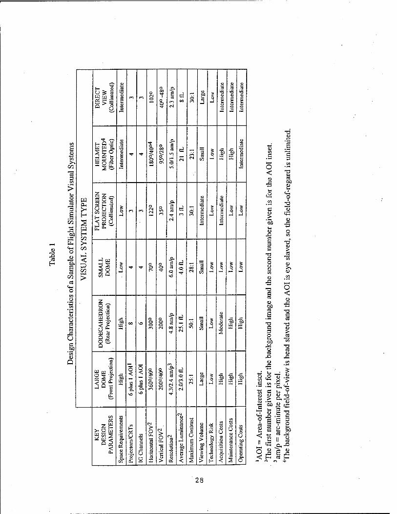
u o u u ^o £— 4J .2 o c ra ca « U ^ ca
5 ,9
•3 u £ u
(»1 m o CN o
00
1
o o
E ca
CN
d 00
Ö u 00 ca J
> o £
3
eg
E u
•a u £
u c c H £Z N—'
■* •— &> Q. Ü
CO
s u CO
E- Q ~ w w H. J A L
E O -2
.3
u £ ■q- ■*
o o g; o o 00
o 00 CN O <n ON
£ ca •n
o
d CN
CN
"eS £
CO
q _"3i oo
E
.2 D £
00 IS in c
ca 3 CO
> O
-4-* W a. .2 u S C3
3 OH
eo u Jj ^ 3 "3 3§^
O m m o CN CN
O ca d o
•5 u £ U
> o
■5 O
£ CO
-X n CN
m CO -J
c
J _J
43 w El °- .2? E-
co E «♦H CO O
"a. £
< <2 >
o ■* TT o o
o o
£ ca
d o ÖÖ
"cä £
CO
5 o
5 o o
5 o
CO J c~ T o CN — _! J J
CO CO
> vd
O CO _o 2 "-E CO 9 =■
c& o
O « s- ca
43
§1 E -5"
a a
90 VO o o o m
o o o CN
ca 00
d
CN
Ö in
"ca £
CO
o
o "ca i- u
•a o s
so
E
JS 00
E
U o & c Q .£? 'co u .^v
Q e o ^m en
111 o
.2P E
O < en
_3 "5.
o < en
_3 Q.
.a o
o" o
o o 51 o o o CN
c
£ ca
-a-
CN ~-^ m
d o
O
CN
'n CN
u 00 I-l ca J
o UP op
E .2P E
\o \o ■^
^—*■
CN CO « OJ
> 2 5 c u £ u
(N > o CN
> o
u c ca c
£ 3
to 2 o
u E
_3 en
(5
en In O O
en en O O u Ü
en "en O
^ u < '3 u en u, CN O O >, c U u
u u ca Q.
CO
o c c 2
C E 3
> oo
SO o c ca c
00
< o 1) "3 a.
o a
5 N
o E
"ca
U >
^3 o en u a.
oa ca u > <
£
ca 2
c
>
o
t—
'In '5 cr u <
'ca u a. O
tu CO
C
o < •4—1
t-4
c2
d >
"5b s-,
3 C
T3 C o o V CO
<D
cd s
T3 C 3 O 00
o CO
0) -4—»
CO «4^
.£ .OT
co 3
1-1 > CD ■"« 'S 00 ►£ »-
3 3 co
T3 s- ca C3X) 1)
«A o
<D IE
CO
O co
-o"
> ca
tu
O < <u
43
TS 3 ca
-3
> ca
ca
II a
§•8
. 5: 13 .a X >
'EL ci ^ ? S.2 1) ■-<
-t—t C4_4
£ 3 i o
CJ s-1
C op ca 44
II g
^43 ca f—.
28
Large dome visual display system. The large dome display design characteristics listed in Table 1 are for the McDonnell Douglas full FOV dome display, developed to train fixed wing fighter pilots (Crane, 1993; 1994). The primary advantages of this system are its very wide FOV and its relatively high-resolution AOI image. (The AOI image is produced by a head-slaved AOI projector.) The primary disadvantages are its large size (7.3 m [24 ft.] diameter dome) and its high life-cycle cost. The dome components are very costly to acquire and to assemble. Acquisition costs also are very high for the seven projectors and the seven IG channels that are required to project the background imagery and the AOI imagery.
This visual display system illustrates the fundamental limitations of dome displays with a large diameter and a large FOV. A large diameter and a large FOV combine to increase the projection area to such an extent that it is very difficult to cover the entire area with high- resolution imagery. In the present case, the projection area was so large that a level of resolution needed for some tasks could not be achieved despite the use of six projectors. An adequate (but unspectacular) level of resolution could be achieved only through the use of the head-slaved AOI projector.
The problems inherent in a large dome, large FOV, front projection visual system are not easily solved by simply decreasing the dome's diameter. When the diameter of the dome display is reduced, projectors located at the proper position inside the dome (near the viewer's eyepoint) obscure the FOV. Attempts to locate projectors outside the dome have been largely unsuccessful because of the image distortions created by locating the projectors a substantial distance from the design eyepoint.
Dodecahedron visual display system. The second column in Table 1 lists the design characteristics for a dodecahedron visual display system that was developed by the Aircrew Training Research Division of Air Force Armstrong Laboratory (Crane, 1993; Geltmacher & Thomas, 1992; Thomas & Reining, 1990). The Display for Advanced Research and Training (DART) is a dome-like visual system consisting of eight segments of a dodecahedron that surround the design eyepoint. Each segment is a rear-projection screen located approximately 1 m from the viewer's head. To reduce IG channel requirements, only six of the eight segments are active. Data from a head-tracking system is used to determine the segments that must be serviced by the IG to provide head-centered imagery.
The main advantages of the DART, relative to a large dome display, are its capability to produce brighter imagery and its somewhat lower cost. However, the DART's resolution (4.75 arc-minutes per pixel) is slightly poorer than that for the background image of the large dome display described above (4.3 arc-minutes per pixel). Also, despite the relatively small viewing distance (about 1 m) and the use of mirrors to fold the optic paths, the DART's space requirements are about the same as for a large dome display. The structural diameter of the DART is 7.3 m (24 ft). It has been estimated that with shorter throw optics, the structural diameter could be reduced to 6.1 m (Thomas & Reining, 1990).
A project was conducted to augment the basic DART with a helmet mounted AOI display image superimposed on the basic DART imagery (Kelly, Shenker, & Weissman, 1992a; Kelly,
29
eye's.spatial sensitivity is greatest) and the low-resolution background image (8.7 arc-minutes per pixel) falls on the peripheral area (where the eye's spatial sensitivity is far lower). Moreover, luminance (21 fL) and contrast ratio (23:1) are high for both background and AOI images.
Despite the many advantages of the FOHMD, independent evaluations have revealed problems that reduce its effectiveness (Brown et al., 1994; Daye et al, 1995) for use in training fixed wing aircraft crewmembers. The primary problems were (a) the helmet is very uncomfortable, (b) it is time-consuming and costly to produce a custom helmet liner for each trainee, and (c) it is time-consuming to perform the required adjustments of the eye tracker and head tracker. Evaluators also reported that the fiber optic bundles constrain head movements, and the quality of the image degrades over time because of breakage of individual fibers.
A great deal of effort continues to be expended in developing lower cost HMDs. Prototype HMDs have been developed using LCD panels (Leinenwever, Best, & Ericksen, 1992a; Rebo & Amburn, 1988), miniature cathode ray tubes (CRTs) (Burley & LaRussa, 1990; Leinenwever, Best, & Ericksen, 1992b; Venturino & Kunze, 1989; Venturino & Wells, 1990), and reflections off the helmet visor (Beamon & Moran, 1990; Carlson & Droessler, 1991). As technology advances, one or more of these HMDs may become cost and training effective. At present, however, they are marginal in one or more of their attributes (e.g., FOV, resolution, comfort, convenience, or cost).
Direct view collimated display. The right-hand column (Column 6) in Table 1 lists design characteristics for the AH-64 CMS produced by Singer-Link. The data in Column 6 were extracted from the design specifications (Naval Training Systems Center, 1991). The AH-64 CMS compares favorably with the other visual display systems discussed above in all respects except horizontal FOV (102°). Resolution (2.3 arc-minutes per pixel), luminance (8 fL), and contrast ratio (30:1) are among the best of the visual display systems listed in Table 1. No recent data were located on the extent to which the production of AH-64 CMSs now in use comply with the design specifications developed by the Naval Training System Center (1991).
Temporal Fidelity
Organization
Temporal fidelity encompasses (a) the amount and synchrony of the simulator component temporal delays (i.e., transport delay), and (b) frequency with which the visual system is updated and refreshed. The two elements of temporal fidelity are discussed below.
31

Transport Delay and Synchrony
Transport delay12 is the delay between the onset of a control input and the onset of the corresponding system response. Excessive transport delays are problematic for all types of systems, but particularly for mamied systems. When excessive, delays prevent the operator of a manned system from perceiving the consequences of control inputs (feedback delay) and making corrective actions in a timely manner.
Because of the disruptive effect of transport delays, rigid standards have been established for the maximum permissible transport delay for aircraft. Standards established for manned military aircraft require that transport delay for flight hardware systems be less than 100 ms (MIL-F-8785C). Transport delays have been of even greater concern for flight simulator manufacturers and users because of the numerous sources of temporal delays, the high cost of minimizing delays, and the effect of delays on training effectiveness.
In the past, an important source of a flight simulator's temporal delay was the computations required to update the aerodynamic model at a sufficiently high rate. However, enormous reductions in the delays associated with aerodynamic model computations have been made possible by the increase in computer processing speed and multiprocessor capabilities. The time required to update the aerodynamic model with contemporary computers is less than the simulated aircraft's transport delay (Bezdek & Moody, 1993). Ongoing development efforts at ARIRWARU have demonstrated the full blade element rotor model (BERM) for the AH-64A can be executed on 200 and 300 MHz Pentium and Pentium II PC platforms, at speeds of 3 to 5 msec. This is the same BERM that runs on the ARI Simulator Training Research Advanced Testbed for Aviation. Despite the increases in computing power, however, there has not been a proportionate reduction in the time to generate the visual scene. The reasons for this are numerous and complex, but one of the most important reasons is the enormous increase in the size, resolution, and complexity of the scene that IGs are required to produce. Other sources of phase lags and/or transport delays include (a) physical data holds in the digital to analog conversion (DAC) process, (b) low pass filters to smooth DAC outputs, (c) data holds between subsystems operating at different iteration rates, and (d) delays or dynamics associated with the display device and motion systems (McMillan, 1991).
The research literature contains numerous references that specify a maximum acceptable transport delay for flight simulators, but there are substantial differences in the values cited. Prior to the time research on the effects of transport delay had been conducted, a maximum of 100 ms was adopted by the simulation industry as their objective, presumably because transport delay of less than 100 ms was required for military aircraft. However, it was not clear whether this de facto standard referred to the total transport delay or the delay that could be added to the aircraft's transport delay (often referred to as the baseline delay). The technical difficulty and
12 The terms "transport delay" and "system lag" are often used interchangeably. The term transport delay is preferred to avoid confusion with "phase lag," a term that is used to describe delays in which the nature of the delay depends on the frequency of the input signal. Phase lags occur in systems that have dynamic elements, such as filters, that change the shape of complex waveforms.
32
high cost of meeting the de facto standard of 100 ms motivated manufacturers and government agencies to initiate research programs to establish empirically the maximum permissible transport delay.
Even after a substantial amount of research had been conducted, the establishment of a maximum permissible transport delay did not prove to be a simple matter. This apparently straightforward task was complicated by the fact that the effect of transport delay was found to vary as a function of (a) measures, tasks, and simulators used to assess the effects of delays, and (b) the criterion used to define an acceptable delay. Among the measures used in one or more of the studies are: in-simulator task performance, handling quality ratings, workload ratings, training effectiveness ratings, training transfer, and simulator sickness. Studies have been conducted in a variety of simulators, including a variable stability aircraft (Bailey, Knotts, Horowitz, & Malone, 1987), but all were simulations of fixed wing aircraft.
Summarized below are conclusions that appear to have reasonably solid support from the research literature. Some of the reports failed to state whether the delays cited were total transport delays or the amount of the delay that was added to the baseline delay for the aircraft. When not stated, it was assumed that the delay values cited in the report are total delays. The ranges of delays that were investigated in the supporting studies are shown in parentheses.
• The effect of delay varies as a function of the axis of aircraft control. Transport delay (100 ms plus baseline delay) tends to degrade lateral axis control more than vertical control (Cooper, Harris, & Sharkey, 1975; Riccio, Cress, & Johnson, 1987) and delay (17ms - 1,400 ms) degrades roll control more than pitch control (Ricard, Norman, & Collyer, 1976).
• Performance in both sluggish and highly responsive systems is degraded by transport delay (47ms-297ms) (Queijo & Riley, 1975). The evidence available suggests that the effect of transport delay (50 ms - 400 ms) on performance (a common task) is about the same for all types of aircraft (Bailey et al., 1987; Riccio et al., 1987).
• Transport delay degrades performance less when motion cues are present than when they are absent. The maximum tolerable delay was 172 ms when motion was present and 297 ms when motion was absent (Miller & Riley, 1976).
• The amount of performance degradation that results from transport delay (110 ms - 300 ms) tends to increase with the difficulty of the task (Middendorf, Fiorita, & McMillan, 1991; Miller & Riley, 1976; Queijo & Riley, 1975; Whiteley & Lusk, 1990).
• Transport delays (100 ms - 400 ms) degrade training transfer in flight simulators (Riccio et al, 1987) and driving simulators (Frank, Casali, & Wierwille, 1988).
• Transport delay in eye and head-tracking systems degrades performance and pilot acceptance (Browder & Chambers, 1988; Naish & Dudfield, 1991; Peters & Turner, 1992; So & Griffin, 1991).
• It is widely assumed that transport delay is related to the incidence and severity of simulator sickness. However, the relationship between transport delay and simulator sickness is not yet known (Frank et al, 1988; Warner, Serfoss, Baruch, & Hubbard,
1992). Few studies have directly addressed the relationship (e.g., Casali & Wierwille, 1980; Frank, Casali, & Wierwille, 1988).
The research findings cited above and perhaps other studies have been used by the FAA and by the USAF to establish standards for the maximum acceptable transport delays for simulators. For Phase I simulators, which are to be used only for certification of certain landing tasks, the FAA specifies that the visual system response time to pilot control input shall not be more than 300 ms greater than the aircraft response delay (Federal Aviation Administration, 1986). For Phase II systems, which are to be used for transition and certification training, the maximum delay is 150 ms greater than the aircraft response delay. The FAA (1994) more recently published transport delay standards for helicopters which specify a maximum delay of 100-150 ms greater than aircraft response delay for certification and advanced flight training.
The FAA also specifies that visual scene changes shall not occur before motion changes but makes no mention of the required level of synchrony between the visual and motion systems. This synchrony requirement apparently was based only on expert opinion and extant technology capabilities. Two objective studies (Casali & Wierwille, 1980; Frank, Casali, & Wierwille, 1988) found that the opposite synchrony was required to minimize simulator sickness. Less sickness resulted when visual onset led motion onset, rather than vice versa.
In a report by McMillan (1991), the following rules of thumb about maximum acceptable transport delays were described. McMillan stated that the USAF Armstrong Laboratory intended to publish these rules of thumb in an official Air Force guide, but no reference to this guide was located during the literature search.
• To ensure level 1 handling qualities in the simulator, the sum of aeromodel equivalent delays, aeromodel pure time delays, and added simulator delays should not exceed 150 ms.
• To minimize delay effects on pilot performance in the simulator, the sum of aeromodel delays and simulator delays should not exceed 200 ms.
• To promote good transfer of training, the sum of aeromodel delays and simulator delays should not exceed 399 ms.
• The same guidelines apply to transport and fighter aircraft.
Very little research data were located concerning the quantitative relationship between simulator sickness and either the magnitude or transport delay or the synchrony in the delays of a visual system and motion system. The lack of data cannot be interpreted as evidence of no causal relationship between delays (magnitude and synchrony) and simulator sickness. The research needed to quantify such relationships is very difficult and very resource intensive. Factors that make such research difficult include the (a) difficulty gaining access to a research simulator; (b) lengthy exposure time required to obtain a single data point; and (c) large sample size required to detect the effect of delay size and synchrony on simulator sickness (McCauley, Hettinger, & Sharkey, 1990).
34
As stated earlier, it probably would not be practical to use a head- or eye-slaved AOI inset in a visual system for the KWCT. Even so, it is worth noting that transport delays inherent in every head- or eye-slaved system can be very annoying and can degrade performance significantly. Research on the maximum acceptable delays for eye-slaved systems indicates that significant performance degradation occurred for delays longer than about 80 ms (Peters & Turner, 1992; So & Griffin, 1991) even though the research subjects were unable to detect a delay until the scene image lagged the eye movement by 180 ms to 230 ms.
Update and Refresh Rates
Most high-end visual display systems employ raster scan displays that are refreshed at 60 Hz. For noninterlaced systems, an electron beam traces every horizontal line, from left to right and from top to bottom, each refresh period. Interlaced systems trace the odd- and even- numbered lines during successive refresh periods. When raster scan displays were in their infancy, a refresh rate of 60 Hz was set as a standard because it was believed that a slower refresh rate would cause the perception of flicker, especially under high luminance conditions. Although a far lower refresh rate can be used in some circumstances without noticeable flicker, it has remained the same because no significant cost savings are realized from using a lower refresh rate.
Update rate refers to the rate at which the IG generates a new scene. Technically, the update rate need not be the same as the refresh rate. When the update rate is less than the refresh rate, the same scene is portrayed on successive refresh cycles until a new scene has been generated by the IG. A lower update rate reduces the computational load, thereby enabling the IG to generate more complex scenes than would be possible at a higher update rate. In addition, temporary reduction in update rate is a method that IGs use to handle situations in which the IG becomes temporarily overloaded. Because of the benefits of lower update rates, both IG manufacturers and their customers are motivated to use the lowest possible update rate.
Although update rate and refresh rate are widely recognized to be important IG design variables, only a few studies were located that investigated their effect on perception and task performance. Conclusions supported by these studies are listed below.
• To minimize the likelihood of perceptual aberrations during a simulated flight, the update rate of an IG should equal the refresh rate of the display device and the display should be noninterlaced (Lindholm, 1992).
• For some combinations of ground speed and terrain surface texture, reducing the update rate to 30 Hz resulted in an increase in apparent speed (Lindholm, Askins, & Krasnicka, 1993).
• To maximize the range at which a moving target can be identified on a visual system, the update rate of the IG should equal the refresh rate of the display device (Lindholm & Martin, 1993).
• Perceptual artifacts, such as jerky motion and multiple images, are common when update rate is 30 Hz or lower, and the severity of the artifacts increase as the angular
35
velocity of scene elements increase. Although the perceptual artifacts can be reduced or eliminated by increasing update rate, update rates exceeding 100 Hz and noninterlaced images are required to eliminate the artifacts associated with very high velocity scene elements (Kellogg & Wagner, 1988).
• Performance on a landing task was degraded moderately when update rate was reduced from 33 Hz to 17 Hz. The degradation became progressively more severe as update rate was reduced further (11 Hz and 6 Hz) (Batson, et al., 1992).
• Manual control research shows that any additional transport delay in the display (even 10 ms) will affect the manual control loop characteristics.
Implications of Findings
Findings on transport delay must be interpreted with caution because all the research was conducted in fixed wing flight simulators. The finding that the maximum acceptable delay was the same for four different types of fixed wing aircraft suggests that,the conclusions probably can be generalized to rotary wing aircraft simulators. Although the cited research literature suggests 200-300 ms visual transport delay might be acceptable, this is regarded as a high risk conclusion for gunnery in a light helicopter. Nowadays the issue is moot, since existing technology should match the transport delay in the OH-58D very closely. Members of the ARI RWARU team believed that a very high degree of fidelity in aircraft response is needed to train Kiowa Warrior pilots to learn to fire their weapons effectively with MFD symbology, as well as with direct vision. If delays in the visual scene are excessive, the handling characteristics of the simulated aircraft will be corrupted even if the fidelity of the aeromodel is very high. These assumptions, though reasonable, can only be validated through future empirical research, using STRATA.
The research findings suggest that (a) the update rate should be the same as the refresh rate, and (b) some performance degradation and perceptual aberrations can be expected if the update rate is lower than 30 Hz. In short, risk would be minimized by establishing a requirement of 60 Hz for both update rate and refresh rate. However, if an update rate of 60 Hz cannot be achieved without a significant loss in scene detail, a lower update rate could be considered with the following caveat. Although anecdotal evidence suggests that effective flight training in helicopter simulators can be accomplished with a 30 Hz update rate, this rate may not be sufficient for the KWCT. A rate of less than 60 Hz may be problematic for the transfer of gun and rocket firing skills. This latter assumption is tentative and underscores the need for empirical research.
The literature provides no basis for recommendations about maximum transport delay or the maximum asynchrony that can be tolerated without significantly increasing the incidence or severity of simulator sickness. It seems reasonable to assume that delays and asynchrony that do not degrade performance will not be large enough to cause a significant increase in simulator sickness.
36
Rapid Prototyping Benchmark Evaluation
Introduction
Gunnery skills sustainment research. As we have learned, the research literature on functional requirements for aerial gunnery simulation is sparse. It is interesting that so little has been learned through research, when one considers that the questions have been around for many years. Thus, questions about the effectiveness of gunnery training simulators and training devices are not new, as the following abstract from a report by Spieth (1952) will illustrate:
Experience during and since World War II has indicated that many synthetic devices, including aerial gunnery simulators, suffer from important deficiencies which seriously impair their effectiveness. These include problems of apparatus malfunction, unreliability (inconsistency) of scores indicative of performance on the equipment, and lack of evidence that training on the device actually resulted in improvement of performance on the trainer itself or in the operational situation toward which training on the device is directed. In order to carry out controlled research on aerial gunnery problems it is essential to have a simulator device which is not subject to the deficiencies mentioned above. This technical report is concerned with apparatus and operating characteristics of a redesigned Pedestal sight Manipulation Test developed to meet this requirement.
The answers to many of the above questions are still not forthcoming nearly 50 years later. Answers depend on research data and little exists. Two ARI research reports evaluated the effectiveness of two Army aerial gunnery simulators for the AH-64A and AH-1 (Hamilton, 1991; McAnulty, 1992). These did not make direct comparisons between simulator subsystems, but were ad hoc evaluations of two simulators currently in service. "The two simulators differed on many parameters, including the technical approaches used for simulating the gunnery mission. Hence, direct comparisons cannot be made. Hamilton (1991) found no evidence that the AH- 64A CMS was effective for the sustainment of gunnery skills, though the short skills decay interval ( 6 mo) and high level of initial train-up of crews may have accounted for the lack of significant difference between the simulator and control groups. On the other hand, McAnulty (1992) demonstrated that the AH-1 Flight and Weapons Simulator (FWS) was an effective skills sustainment device. The skill decay interval in the McAnulty study was 15 months, making these two research projects noncomparable. Another approach to determining the effectiveness of a training system is usability assessment in which the opinions of users or potential users of the product are sought. Usability assessments can be performed on systems that are currently fielded, with the goal of improving their functionality and design, or before a system is fielded. In the latter case, the usability assessment becomes part of a front-end analysis (FEA). Only one usability assessment having a direct bearing upon helicopter gunnery was located by the authors (Silverman & Spiker, 1996).
The OH-58D simulator testbed. The OH-58D simulator used in this evaluation consisted of a cockpit shell with functional mission equipment package (MEP) controls and displays. An operating PDU reticle was not integrated into the simulation in time for evaluation. The out-the-
37
window and heads-down visual displays were provided via an Evans and Sutherland ESIG 3000 Image Generator (three channels) and two Electrohome rear-projection displays (FOV = 45° x 120°). The projection screens represented cockpit windows. The pilot, in the right seat, had a window to this right and one directly ahead; the CPO, in the left seat, did not have a side window but was able to view the center screen. A Silicon Graphics Iris Onyx served as the host computer. A BERM based on an AH-64A software flight model was adapted to the OH-58D simulation. The visual database represented a section of NTC at Fort Irwin, California. The tactical engagement software model used was the Interactive Tactical Environment Management System (ITEMS). Targets were representations of Russian BMP fighting vehicles situated at various locations around Bicycle Lake, which served as the virtual gunnery range.
Overview of rapid prototyping evaluation . OH-58D crews performed a mission profile in the benchmark simulator. Gunnery performance was evaluated via automated performance measures (APM)s. Participants were administered questionnaires to evaluate the physical and . functional fidelity of the OH-58D simulator. The FEA was driven by cost and time constraints. ARIRWARU was not able to explore the entire cost/ complexity continuum with a completely balanced, factorial research design. Instead, two benchmark configurations were evaluated as candidates for a low-end KWCT, keeping cost/complexity tradeoffs in mind.
Method
Procedure. Participants were eight rated OH-58D IPs, current in the aircraft, from an operational training unit. Total flight time in the aircraft ranged from 1000 to 3700 hr, with a mean of 2025 hr (SD = 989.95). All were males, ages 28 to 50 yr £M = 39.20, SD = 6.70), who volunteered to take part in the evaluation. They were scheduled in pairs, with each pair comprising an OH-58D crew (Pilot and CPO). Each pair reported to ARI's STRATA facility at the pre-arranged time, and were briefed on the rationale behind the FEA. Emphasis was on the current dearth of behavioral data regarding the fidelity requirements for simulators and other tactical training devices. They were then given a questionnaire (Appendix A) to elicit background information regarding OH-58D flight hours and attitudes toward the efficacy of simulation. Next, they were asked to designate which member of the pair would be pilot and which would be CPO.
Independent variables. The same mission profile was completed under three visual display conditions, whose order was counterbalanced. The two variables upon which these conditions were based were: Resolution (480/768 horizontal lines) and number of Windows (one/two). The number of horizontal lines displayed was coordinated to Resolution; the number of windows was coordinated to FOV. The three conditions were: 768 lines/one window, 768 lines/two windows, and 480 lines/two windows. It was the judgment of the investigators that the 480 lines/one window combination not be used; previous demonstrations with the same configuration had shown navigation to be difficult. Hence, there was some deliberate confounding of Resolution and FOV.
Mission profile. Ballistic gunnery practice was the focus of the simulated mission. For this reason, it was decided not to employ the aircraft's navigation and communication systems; the MEP tasks were of primary importance. The terrain at Bicycle Lake Army Airfield is high desert with
38
sparse vegetation; terrain relief varies from flat valleys to rolling hills and mountains. The mission was a daylight attack on targets in a refueling area. The OH-58D crew was instructed to depart from a preset Start Point, and fly to Firing Point 1 (FP-1) and FP- 2. The mode of flight was contour at 80 knots. The crew would follow a virtual automated scout aircraft (Autoscout), another OH-58D generated by ITEMS, to FP-1. Upon arrival at FP-1, Autoscout stopped for 120 sec. The crew then engaged the first target, a BMP armored vehicle, from a distance of 1200 meters. After 120 sec had elapsed, Autoscout continued toward FP-2, located at the SE edge of Bicycle Lake. At FP-2, the OH- 58D crew engaged four stationary BMPs and one stationary ZSU-23/4, which formed an N-S column along the Western edge of the lake. Maximum engagement ranges were 2500 to 3500 m. Targets could be engaged via the .50 cal machine gun and 2.75 in folding-fin rockets. Since all targets were considered "soft-skin" lightly-armored vehicles, direct hits by any of the weapons caused targets to show visual signs of damage (burn).
Dependent measures. After each mission iteration, the crew was asked to rate (7 pt scale) the adequacy of the simulation for the performance of the gunnery and non-gunnery tasks which comprised the mission that it had just completed. Each crew member completed two questionnaires, (Appendix B), one keyed to the resolution of the visual display system and the other to the FOV. This procedure was repeated three times for each crew, for each Resolution/FOV combination.
Objective scoring of gunnery accuracy was accomplished through the use of automated performance measures (APMs) collected continuously at the rate of 1 Hz. These comprised the engagement distance in meters to the target and impact point of each round relative to the target, in terms of x/y coordinates. The number of rounds falling in pre-specified "boxes" around the target based on Gunnery Table VIII was used as a measure of gunnery accuracy.
Results
Reports of simulator sickness. One crew member reported symptoms of nausea after completing the gunnery mission in the Low Resolution/2 Window condition. He was subsequently administered the Simulator Side Effects and Motion History Questionnaires (adapted from Kennedy, Lane, Berbaum, & Lilienthal, 1993). The crew was excused from further participation in the evaluation. Consequently, data were not available for this particular crew for the High Resolution/One Window condition. It was later determined that the update rate had been erroneously set at 30 Hz for this crew (default was 60 Hz). No other instances of simulator sickness .
Gunnery accuracy. Scoring was accomplished by determining how many rounds impacted within a standard 36 x 36 m (gun) or 300 x 400 m (rocket) box, based on the (x,y) coordinates of the target (target coordinates were 0,0). The comparisons presented below in Table 2 consist of the High and Low Resolution, Two Window conditions for which complete data sets are available. Because of the small sample size, conventional probability (p) levels may not be very meaningful. For this reason, no statistical tests were performed on the data.
39
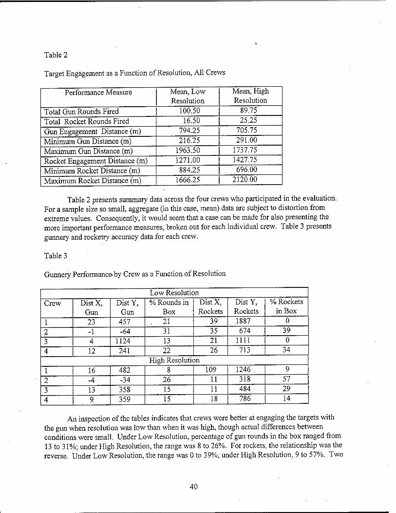
Table 2
Target Engagement as a Function of Resolution, All Crews
Performance Measure Mean, Low Resolution
Mean, High Resolution
Total Gun Rounds Fired 100.50 89.75
Total Rocket Rounds Fired 16.50 25.25
Gun Engagement Distance (m) 794.25 705.75
Minimum Gun Distance (m) 216.25 291.00
Maximum Gun Distance (m) 1963.50 1737.75
Rocket Engagement Distance (m) 1271.00 1427.75
Minimum Rocket Distance (m) 884.25 696.00
Maximum Rocket Distance (m) 1666.25 2120.00
Table 2 presents summary data across the four crews who participated in the evaluation. For a sample size so small, aggregate (in this case, mean) data are subject to distortion from extreme values. Consequently, it would seem that a case can be made for also presenting the more important performance measures, broken out for each individual crew. Table 3 presents gunnery and rocketry accuracy data for each crew.
Table 3
Gunnery Performance, by Crew as a Function of Resolution
Low Resolution Crew Dist X,
Gun Dist Y,
Gun % Rounds in
Box Dist X, Rockets
Dist Y, Rockets
% Rockets in Box
1 23 457 . 21 39 1887 0
2 -1 -64 31 35 674 39
3 4 1124 13 21 1111 0
4 12 241 22 26 713 34 High Resolution
1 16 482 8 109 1246 . 9
2 -4 -34 26 11 318 57
3 13 358 15 11 484 29
4 9 359 15 18 786 14
An inspection of the tables indicates that crews were better at engaging the targets with the gun when resolution was low than when it was high, though actual differences between conditions were small. Under Low Resolution, percentage of gun rounds in the box ranged from 13 to 31%; under High Resolution, the range was 8 to 26%. For rockets, the relationship was the reverse. Under Low Resolution, the range was 0 to 39%; under High Resolution, 9 to 57%. Two
40
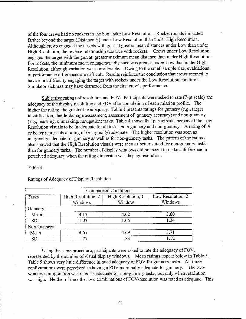
of the four crews had no rockets in the box under Low Resolution. Rocket rounds impacted farther beyond the target (Distance Y) under Low Resolution than under High Resolution. Although crews engaged the targets with guns at greater mean distances under Low than under High Resolution, the reverse relationship was true with rockets. Crews under Low Resolution engaged the target with the gun at greater maximum mean distance than under High Resolution. For rockets, the minimum mean engagement distance was greater under Low than under High Resolution, although variation was considerable. Owing to the small sample size, evaluations of performance differences are difficult. Results reinforce the conclusion that crews seemed to have more difficulty engaging the target with rockets under the Low Resolution condition. Simulator sickness may have detracted from the first crew's performance.
Subjective ratings of resolution and FOV. Participants were asked to rate (7-pt scale) the adequacy of the display resolution and FOV after completion of each mission profile. The higher the rating, the greater the adequacy. Table 4 presents ratings for gunnery (e.g., target identification, battle-damage assessment, assessment of gunnery accuracy) and non-gunnery (e.g., masking, unmasking, navigation) tasks. Table 4 shows that participants perceived the Low Resolution visuals to be inadequate for all tasks, both gunnery and non-gunnery. A rating of 4 or better represents a rating of (marginally) adequate. The higher resolution was seen as marginally adequate for gunnery as well as for non-gunnery tasks. The pattern of the ratings also showed that the High Resolution visuals were seen as better suited for non-gunnery tasks than for gunnery tasks. The number of display windows did not seem to make a difference in perceived adequacy when the rating dimension was display resolution.
Table 4
Ratings of Adequacy of Display Resolution
Compari son Conditions Tasks High Resolution, 2
Windows High Resolution, 1
Window Low Resolution, 2
Windows Gunnery
Mean 4.13 4.02 3.60 SD 1.03 1.06 1.34
Non-Gunnery Mean 4.61 4.69 3.71 SD .77 .83 1.12
Using the same procedure, participants were asked to rate the adequacy of FOV, represented by the number of visual display windows. Mean ratings appear below in Table 5. Table 5 shows very little difference in rated adequacy of FOV for gunnery tasks. All three configurations were perceived as having a FOV marginally adequate for gunnery. The two- window configuration was rated as adequate for non-gunnery tasks, but only when resolution was high. Neither of the other two combinations of FOV-resolution was rated as adequate. This
41
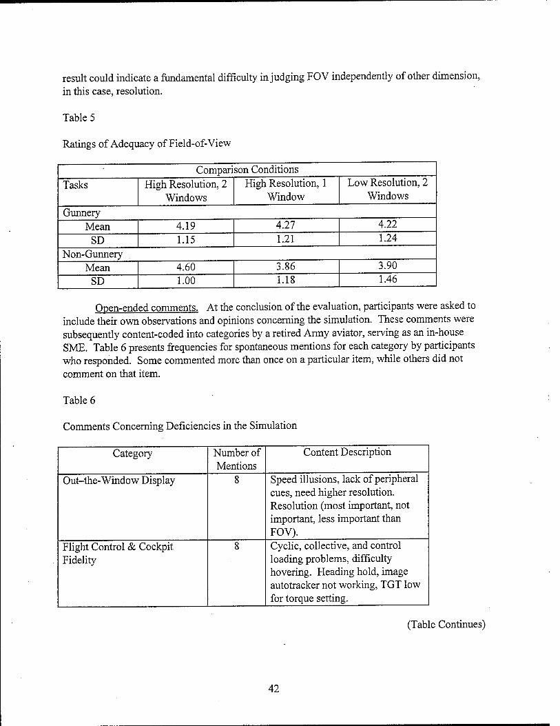
result could indicate a fundamental difficulty in judging FOV independently of other dimension, in this case, resolution.
Table 5
Ratings of Adequacy of Field-of-View
Comparison Conditions
Tasks High Resolution, 2 Windows
High Resolution, 1 Window
Low Resolution, 2 Windows
Gunnery Mean 4.19 4.27 4.22
SD 1.15 1.21 1.24
Non-Gunnery Mean 4.60 3.86 3.90
SD 1.00 1.18 1.46
Open-ended comments. At the conclusion of the evaluation, participants were asked to include their own observations and opinions concerning the simulation. These comments were subsequently content-coded into categories by a retired Army aviator, serving as an in-house SME. Table 6 presents frequencies for spontaneous mentions for each category by participants who responded. Some commented more than once on a particular item, while others did not comment on that item.
Table 6
Comments Concerning Deficiencies in the Simulation
Category Number of Mentions
Content Description
Out-the-Window Display 8 Speed illusions, lack of peripheral cues, need higher resolution. Resolution (most important, not important, less important than FOV).
Flight Control & Cockpit Fidelity
8 Cyclic, collective, and control loading problems, difficulty hovering. Heading hold, image autotracker not working, TGT low for torque setting.
(Table Continues)
42
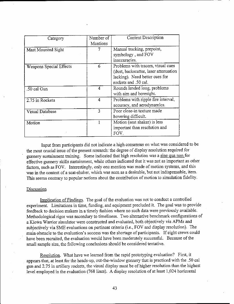
Category Number of Mentions
Content Description
Mast Mounted Sight 7 Manual tracking, preprint, symbology, and FOV inaccuracies.
Weapons Special Effects 6 Problems with tracers, visual cues (dust, backscatter, laser attenuation lacking). Need better cues for rockets and .50 cal.
.50 cal Gun 4 Rounds landed long, problems with aim and boresight.
2.75 in Rockets 4 Problems with ripple fire interval, accuracy, and aerodynamics.
Visual Database 3 Poor close-in texture made hovering difficult.
Motion 1 Motion (seat shaker) is less important than resolution and FOV.
Input from participants did not indicate a high consensus on what was considered to be the most crucial issue of the present research: the degree of display resolution required for gunnery sustainment training. Some indicated that high resolution was a sine qua non for effective gunnery skills sustainment, while others indicated that it was not as important as other factors, such as FOV. Interestingly, only one mention was made of motion systems, and this was in the context of a seat-shaker, which was seen as a desirable, but not indispensable, item. This seems contrary to popular notions about the contribution of motion to simulation fidelity.
Discussion
Implication of Findings. The goal of the evaluation was not to conduct a controlled experiment. Limitations in time, funding, and equipment precluded it. The goal was to provide feedback to decision makers in a timely fashion where no such data were previously available. Methodological rigor was secondary to timeliness. Two alternative benchmark configurations of a Kiowa Warrior simulator were constructed and evaluated, both objectively via APMs and subjectively via SME evaluations on pertinent criteria (i.e., FOV and display resolution). The main obstacle to the evaluation's success was the shortage of participants. If eight crews could have been recruited, the evaluation would have been moderately successful. Because of the small sample size, the following conclusions should be considered tentative.
Resolution. What have we learned from the rapid prototyping evaluation? First, it appears that, at least for the heads-up, out-the-window gunnery that is practiced with the .50 cal gun and 2.75 in artillery rockets, the visual display must be of higher resolution than the highest level employed in the evaluation (768 lines). A display resolution of at least 1,024 horizontal
43
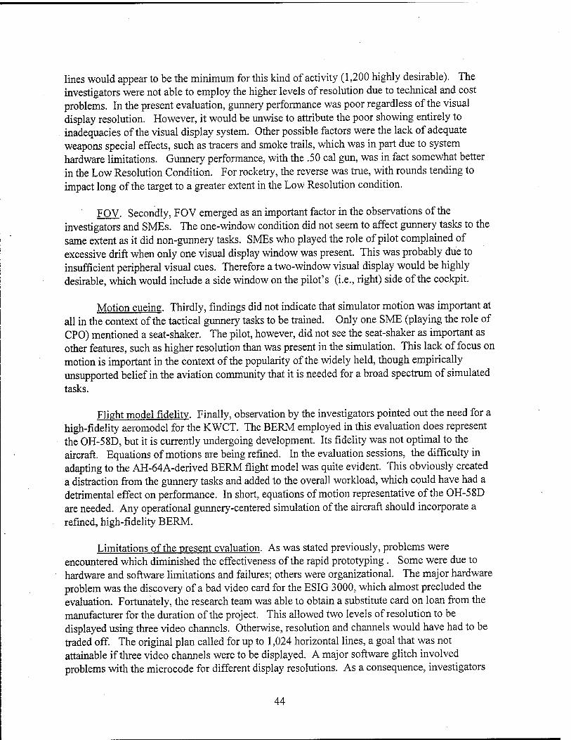
lines would appear to be the minimum for this kind of activity (1,200 highly desirable). The investigators were not able to employ the higher levels of resolution due to technical and cost problems. In the present evaluation, gunnery performance was poor regardless of the visual display resolution. However, it would be unwise to attribute the poor showing entirely to inadequacies of the visual display system. Other possible factors were the lack of adequate weapons special effects, such as tracers and smoke trails, which was in part due to system hardware limitations. Gunnery performance, with the .50 cal gun, was in fact somewhat better in the Low Resolution Condition. For rocketry, the reverse was true, with rounds tending to impact long of the target to a greater extent in the Low Resolution condition.
FOV. Secondly, FOV emerged as an important factor in the observations of the investigators and SMEs. The one-window condition did not seem to affect gunnery tasks to the same extent as it did non-gunnery tasks. SMEs who played the role of pilot complained of excessive drift when only one visual display window was present. This was probably due to insufficient peripheral visual cues. Therefore a two-window visual display would be highly desirable, which would include a side window on the pilot's (i.e., right) side of the cockpit.
Motion cueing. Thirdly, findings did not indicate that simulator motion was important at all in the context of the tactical gunnery tasks to be trained. Only one SME (playing the role of CPO) mentioned a seat-shaker. The pilot, however, did not see the seat-shaker as important as other features, such as higher resolution than was present in the simulation. This lack of focus on motion is important in the context of the popularity of the widely held, though empirically unsupported belief in the aviation community that it is needed for a broad spectrum of simulated tasks.
Flight model fidelity. Finally, observation by the investigators pointed out the need for a high-fidelity aeromodel for the KWCT. The BERM employed in this evaluation does represent the OH-58D, but it is currently undergoing development. Its fidelity was not optimal to the aircraft. Equations of motions are being refined. In the evaluation sessions, the difficulty in adapting to the AH-64A-derived BERM flight model was quite evident. This obviously created a distraction from the gunnery tasks and added to the overall workload, which could have had a detrimental effect on performance. In short, equations of motion representative of the OH-58D are needed. Any operational gunnery-centered simulation of the aircraft should incorporate a refined, high-fidelity BERM.
Limitations of the present evaluation. As was stated previously, problems were encountered which diminished the effectiveness of the rapid prototyping . Some were due to hardware and software limitations and failures; others were organizational. The major hardware problem was the discovery of a bad video card for the ESIG 3000, which almost precluded the evaluation. Fortunately, the research team was able to obtain a substitute card on loan from the manufacturer for the duration of the project. This allowed two levels of resolution to be displayed using three video channels. Otherwise, resolution and channels would have had to be traded off. The original plan called for up to 1,024 horizontal lines, a goal that was not attainable if three video channels were to be displayed. A major software glitch involved problems with the microcode for different display resolutions. As a consequence, investigators
44
could not display a third level of resolution (600 horizontal lines). Another software problem prevented the use of the preferred visual database (Fort Hunter-Liggett, California) which provided better contrast and more terrain features than the NTC database.
Another problem encountered was related to neither hardware nor software. The research team was not able to obtain the participation of enough crews to provide an adequate sample for valid statistical comparisons between the independent variables. Nine crews were requested and four were provided.
Another important issue that could not be addressed in the evaluation was the transfer of training from a gunnery-focused simulator to the aircraft on the firing range. Only experienced crews participated in the evaluation. It was evident that MEP-related procedural skills did transfer to the simulator, though the transfer of piloting and gunnery skills was harder to evaluate. Further, if the simulator were shown to be adequate for the sustainment of gunnery skills, this does not imply that it would equally effective for their acquisition. Likewise, there is no evidence, as of the current writing, of a ballistic (e.g., .50 cal gun and 2.75 in rockets) aerial gunnery trainer that has been demonstrated to be training effective, let alone a substitute for practice in the aircraft.
General Conclusions
One consistent finding of the literature review was a dearth of selective fidelity research having a bearing on rotary wing flight, especially with regard to tactical gunnery. The preponderance of studies conducted to investigate fidelity requirements for aviation simulation were germane to fixed wing flight. The simulation technology has progressed dramatically within the past decade, yet the knowledge base has remained relatively static. One reason for this is because much of the research on aviation simulation has been narrowly focused on operational simulators in specific training situations and on individual as opposed to crew-level skills. Hays, Jacobs, Prince, & Salas (1972) state that this limited perspective has been dictated by the need to employ the simulator first as a training device, and then to attempt to demonstrate its effectiveness. This is understandable, since with few exceptions (Collyer & Chambers, 1978; Larson & Terry, 1975) simulators have been built and sold for training, not for research. Simulator training effectiveness has been assumed but, in most cases, not demonstrated. Historically, investigators have been concerned with demonstrating that training time in the simulator transfers to the aircraft for their particular device at its particular location. The minimum amount of simulator complexity (e.g., visual display resolution, FOV, motion cueing) required to achieve a given set of training objectives is seldom addressed. This seeming indifference to empirically-based research on simulator functional requirements has resulted in an inadequate knowledge base, and a paucity of constructs that can be applied by simulator developers, who have a need for such information. This is especially pertinent to helicopter simulation in the tactical mission environment. The developer has little to go on and must base his or her decision on deficient data, much of it anecdotal.
The training requirements analysis and literature review were intended to assist the decision-maker with a perspective on the current technological approaches to military flight
45
Simulation, with an emphasis on capabilities, costs, and tradeoffs. The analysis of the literature surveyed focused on the functional requirements for a KWCT. This necessitated a close examination of those flight maneuvers that were likely to be trained and sustained in the simulator, and a comprehensive review of the research literature to assess the training technologies and their relative effectiveness. The decision-maker must consider options and tradeoffs during the process of acquiring and integrating a tactical simulator. There are alternate approaches to accomplish a given training objective, depending upon available resources and technologies. For this reason, no monolithic recommendations were made which designated a specific technological approach as the only one which would be suited for the training tasks at hand. Throughout, it was acknowledged that alternative technical approaches existed, and that the rapid rate of technical evolution made it unfeasible to make dogmatic assertions of the technologies that should be employed.
Still, the investigators believe that the findings gleaned from the current reviews are of value to decision-makers, who themselves may not have the time to access such information. The findings also have uncovered important issues that can only be resolved by comprehensive programs of empirical research. If this effort has, in any way, affected the decision-making process, then it should be regarded as a successful endeavor. Finally, the major issues considerations and tradeoffs should not limit the scope of this project to the KWCT. Many of these issues are generalizable across training devices representing future rotary wing aircraft.
The preceding discussion concerned itself with the current status of simulator training requirements research. We now must ask about future directions in the research. From the literature review, it became evident that a comprehensive, programmatic research effort is needed for the rotary wing training community. Thus far selective fidelity research has been piecemeal, and lacking in generalizability. One reason for this is the lack of dedicated, research testbed facilities for rotary wing simulation. An exception is ARI RWARU's STRATA, which has the capability of investigating many of the issues discussed in the present. The Kiowa Warrior rapid prototyping was an attempt to demonstrate how STRATA can be used to evaluate the effects of different levels of simulator subsystem fidelity (in this case, the visual display system) on aircrew performance.
Although the rapid prototyping evaluation did not explore all of the visual display parameters originally intended, it is still possible to offer specific recommendations on a baseline configuration for an OH-58D gunnery trainer. It has been previously stated that visual display resolution should be greater than the maximum level (768 lines) employed in the-
evaluation. A resolution of at least 1,000 horizontal display lines would probably be adequate; 1,200 lines would be better, especially for rocketry. AOI insets that increase targets' resolution would be desirable. Two visual display windows seem to be necessary if the crew is going to practice a tactical mission scenario involving more than stationary gunnery. The results of the evaluation provided no strong evidence that motion cueing is needed for a KWCT. Thus a fixed base device seems adequate. The equations of motion for the computer flight model are critical. The BERM for the benchmark simulator in the present evaluation did represent the OH-58D, but it evolved (and is still evolving) from a BERM representing the AH-64A. Thus it was not at a level of refinement where it could be called a true OH-58D flight model. Likewise, the control
46
loading was not correct for the aircraft type. A KWCT should have a high-resolution, high- fidelity BERM (or alternative flight model). Observation of crews in the evaluation indicated that MEP fidelity must be fully representative ofthat found on the aircraft, including the number of lines in the MFD display. Kinesthetic feedback from switches, bezel buttons, and other controls is critical. This is especially true if the crew interactions that comprise a realistic mission are to be incorporated into a tactical mission simulation report.
The phrase: "further research is needed" has virtually become a cliche among behavioral scientists. In the instance of the present investigation, it is a truism. This entire research effort revealed a paucity of hard evidence upon which to base functional requirements for military flight simulators, whether fixed or rotary wing. In spite of the problems encountered, the rapid prototyping evaluation illustrated how investigators can build a set of requirement constructs. In short, we were able to pinpoint a major problem, and to demonstrate how the problem could be alleviated.
47
References
AGARD. (1981). Characteristics of flight simulator visual systems (NATO AGARD- AR-164, AD A101445). Neuilly-sur-Seine, France: Advisory Group for Aerospace Research and Development (AGARD).
Andre, A.D., & Johnson, W. W. (1992). Stereo effectiveness evaluation for precision hover tasks in a helmet-mounted display simulator. Paper presented at the 1992 IEEE International Conference on Systems, Man, and Cybernetics., New York, NY.
Army, (1992). Operators manual for Armv OH-58D helicopter (TM 55-1520-248-10). Washington, D.C.: Headquarters Department of the Army.
Bailey, R. E., Knotts, L E., Horowitz, S. J., & Malone, H. L. (1987). Effect of time delay on manual flight control and flying qualities during in-flight and ground-hased simulatioa Paper presented at the AIAA Flight Simulation Technologies Conference, Washington, D.C.
Barber, B., Burbidge, D., & Roberts, M. E. C. (1987). API displays for operational training. Paper presented at the Proceedings of the 1987 IMAGE IV Conference, Tempe, AZ.
Barrette, R., Dunkley, K., Kruk, R, Kurts, D, Marshall, S., Williams, T., Weissman, P., & Antos, S. (1990). Flight simulator: Advanced wide Field of view, helmet-mounted, infinity display system. Williams AFB, AZ: Operations Training Division, Air Force Human Resources Laboratory.
Batson, W. M., Harris, R. L., & Houck, J. A. (1992). Effect of display parameters on pilots' ability to approach, flare and land. Paper presented at the AIAA/AHS Flight Simulation Technologies Conference, Washington, D.C.
Beamon, W. S., & Moran, S. I. (1990). Raster graphic helmet-mounted display study. Washington, D.C: National Aeronautics and Space Administration.
Beaton, R. J., & Farley, W. W. (1991). Comparative study of the MTFA. ICS. and SORI image quality metrics for visual display systems. Wright-Patterson AFB, OH: Human Engineering Division, Armstrong Laboratory.
Bess, R. D. (1989). Tradeoffs in the configuration of computer image generation systems. Paper presented at the 11th Interservice/Industry Training systems Conference, Arlington, VA.
Bezdek, W. J., & Moody, L. A. (1993). Dynamic simulation fidelity improvement using transfer function state extrapolation. Paper presented at the AIAA Flight Simulation Technologies Conference, Washington, DC.
49

Boursette, J. F., & Michot, J. L. (1994). COSMOS - A new concept for a multi-mission trainer. Paper presented at the 5th International Training Equipment Conference and Exhibition, Warminster, Wiltshire, UK.
Bridgwater, R. J. (1992). Increased vertical field of view for wide-angle collimated displays. Paper presented at the 1992 IMAGE VI Conference, Tempe, AZ.
Browder, G. B., & Chambers, W. S. (1988). Eve-slaved area-of-interest display systems: Demonstrated feasible in the laboratory. Paper presented at the AIAA Flight Simulation Technologies Conference, Washington, DC
Brown, J. E., Lincourt, T. J., Leos, M. J., Poe, D. R., Allard, G. S., & Charpilloz, K. D. (1994). Visual System Operational Evaluation. Wright Patterson Air Force Base, Ohio: Training Systems Product Group, Aeronautical Systems Center (ASC/YW), Wright- Patterson AFB, Ohio
Buckland, G. H., Edwards, B. J., & Stevens, C. W. (1981). Flight simulator visual and instructional features for terrain flight simulatioa Paper presented at the IMAGE Conference n, Phoenix, AX.
Burley, J. R, & LaRussa, J. A. (1990). A full-color wide-field of view holographic helmet- mounted display for pilot/copilot interface development and human factors studies. Paper presented at the Proceedings of SPIE-The International Society for Optical Engineering, Bellingham, WA.
Carlson, A. L., & Droessler, J. (1991). Development of a binocular visor projection helmet- mounted display. Paper presented at the SID International Symposium Digest of Technical Papers, Playa del Rey, CA.
Casali, J.G., & Wierwille, W.W. (1980). The effects of various design alternatives on moving-base driving simulator discomfort. Human Factors. 22(6), 741-756.
Collyer, S.C., and Chambers, W.S. (1978). AWAVS, a research facility for defining flight trainer visual requirements. Proceedings of the Human Factors Society 22nd Annual Meeting. Santa Monica, CA: Human Factors Society.
Cooper, F. R, Harris, W. T., & Sharkey, v. J. (1975). The effect of delay in the presentation of visual information on pilot performance (NAVTRAEQUIPCENIH-250). Orlando, FL: Naval Training Equipment Center.
Costenbader, J. L. (1984). CIG data bases in an instance: Bits and pieces. Paper presented at the IMAGE III Conference, Tempe, AZ.
50

Crane, P. M. (1993). Evaluation of two wide field of view display systems for air combat training. Paper presented at the Proceedings of the 13th International Display Research Conference, Brive, France.
Crane, P. M. (1994). Evaluation of two wide Field of View display systems for air combat training. Journal of the Society for Information Display. 2(1), 59-61.
Cross, K. D. (1996). Advanced visual display technology for JAST training and mission rehearsal (Technical Memorandum ASITM-96158-10). Fort Walton Beach, FL: Anacapa Sciences, Inc.
Cross, K. D., Dohme, J. A., & Howse, W. R. (in preparation). Observations about defining collective training requirements (ARI Technical Report). Alexandria, VA: U.S. Army Research Institute for the Behavioral and Social Sciences.
Daye, H., Stice, B., Cariello, M., Ayres, J., Hook, L., Midthun, C, Gast, S., Wallace, F. T., Reeves, M., Brown, J. E., Heintzman, R., & Wilson, J. (1995). Joint visual system operational evaluation (JOINT VIS-EVAD: Site 1 CAE advanced fiber optic HMD (AFOHMD). Manassas, Virginia: SIMTEC, Inc.
DeMaio, J., Rinalducci, E. J., Broods, R, & Brunderman, J. (1983). Visual cuing effectiveness: Comparison of perception and flying performance. Paper presented at the 5th Annual Interservice/Industry Training Equipment Conference, Arlington, VA.
Dixon, K. W., & Curry, D. G. (1987). Effect of scene content and field of view on weapons delivery training. Paper presented at the Proceedings of the 9th Interservice/Industry Training Systems Conference, Arlington, VA.
Dixon, K. W., Martin, E. L., & Krueger, G. M. (1990). Effects of field of view sizes on pop-up weapons delivery. Williams AFB, AZ: Operations Training Division, Air Force Human Resources Laboratory.
Dixon, W. K., & Curry, D. G. (1990). Weapons delivery training: Effects of scene content and field of view. Williams AFB, AZ: Operations Training Division, Air Force Human Resources Laboratory.
Dugdale, J. (1993). Low-cost visual display technology. Paper presented at the Proceedings of the 1993 Simulation Multiconference on the International Simulators Conference, San Diego, CA.
Dugdale, J. (1994). New advanced single seat visual display. Paper presented at the 1994 IMAGE VQ Conference, Tempe, AZ.
51
Ericksen, R. A. (1978). Line criteria in target acquisition with television. Human Factors, 20(5), 573-588.
Evans R (1990) Tmage quality metrics and performance of visual display systems. Paper ' presented at the Proceedings of the 1990 IMAGE V Conference, Tempe, AZ.
Evans R J (1993). Tmage quality and the display modulation transfer function: Experimental ' findings. Williams AFB, AZ: Aircrew Training Research Division, Armstrong Laboratory.
Federal Aviation Administration. (1980). Aircraft simulator and visual system evaluation and approval (Advisory Circular 121-14C). Washington, D.C: Department of Transportation.
Federal Aviation Administration. (1986). Airplane simulator and visual system evaluation (FAA Advisory Circular No. 120-40A). Washington, D.C: Federal Aviation Administration.
Federal Aviation Administration. (1994). Helicopter simulator qualification. (Advisory Circular 120-63). Washington, D.C. Federal Aviation Administration.
Fox T A & Clark P. D. (1986). Development of computer-generated imagery for a low-cost realtime terrain imaging system. Paper presented at the IEEE Conference on Aerospace and Electronics, New York, NY.
Frank, L. H., Casali, J. G., & Wierwille, W. W. (1988). Effects of visual display and motion ' system delays on operator performance and uneasiness in a driving simulator. Human
Fjctors,_30i2), 201-217.
Gallimore, J. J. (1991). Review of psvchophvsicallv-hased image quality metrics. Dayton, OH: Logicon Technical Services, Inc.
Geltmacher H & Thomas, M. (1992). An overview of Air Force combat simulator display development and performance. Paper presented at the 1992 SID International Symposium, PlayadelRey,CA.
Grunwald A J., & Kohn, S. (1994). Visual field information in low-altitude visual flight by line- of-sight slaved helmet-mounted displays. TREE Transactions on Systems, Man, and Cybernetics. Volume 24, 120-134.
Grunwald A J., Kohn, S., & Merhav, S. J. (1991). Visual field information in nap-of-the-earth flipht hv teleoperated helmet-mounted displays. Paper presented at the Proceedings of the SPIE-International Society for Optical Engineering, San Jose, CA.
Hamilton D B (1991). Training effectiveness of the AH-64A Combat Mission Simulator fnrcnstaining gunnery skills. (Res. Rept. 1604). Alexandria, VA: U.S. Army Research Institute for the Behavioral and Social Sciences.
52

Harris, J. (1974). Study to explore the relationships between visual senses performance and adaptation level. San Diego, CA: Scripps Institution of Oceanography Visibility Laboratory.
Hays, R.T., Jacobs, J.W., Prince, C. & Salas, E. (1992) Right simulator training effectiveness: A meta-analysis. Military Psychology. 4(2), 63-74.
Hsu, S. C. (1986). The Kell factor: Past and present. Society of Motion Picture and Television Engineers Journal. February, 206-214.
Hughes, D. A. (1992). Multiple projector small dome display. Williams AFB, AZ: Aircrew Training Research Division, Armstrong Laboratory.
Iavecchia, J. H., Iavecchia, H. P., & Roscoe, S. N. (1988). Eye accommodation to head-up virtual images. Human Factors. 30(6), 689-702.
Jorna, G. C. (1993). MTF measurements, image-aualitv metrics, and subjective image quality for soft-copy color images. Paper presented at the 1993 SID International Symposium Digest of Technical Papers, Playa del Rey, CA.
Katz, A. (1997). The minimal ARMS system (UA FDL Report No. 97S01B). Tuscaloosa, AL: University of Alabama Flight Dynamics Laboratory.
Kaufman, J. E. (Ed.). (1966). Lighting Handbook. Washington, DC: Illuminating Engineering Society.
Kellogg, G. V., & Wagner, C. A. (1988). Effects of update and refresh rates on flight simulation visual displays. Edwards, CA: Hugh L. Dryden Flight Research Center, National Aeronautics and Space Administration.
Kelly, G., Shenker, M., & Weissman, P. (1992a). Helmet-mounted area-of-interest. Paper presented at the Proceedings of SPIE-The International Society for Optical Engineering, Bellingham, WA.
Kelly, G. R., Shenker, M., & Weissman, P. (1992b). Helmet-mounted area-of-interest display. Williams AFB, AZ: Aircrew Training Research Division, Armstrong Laboratory.
Kennedy, R. S., Lane, N.E., Berbaum, K.S., & Lilienthal, M.G. (1993). Simulator Sickness Questionnaire: An enhanced method for quantifying simulator sickness. International Journal of Aviation Psychology. 3(3). 203-220.
53

Kennedy, R. S., & Lilienthal, M. G. (1994). Measurement and control of motion sickness aftereffects from immersion in virtual reality. Virtual Reality and Medicine: The Cutting Edge. Official Proceedings of Virtual Reality and Medicine (pp. 111-119). New York: Sig-Advanced Applications, Inc.
Kennedy, R. S., & Lilienthal, M. G. (1995). Implications of balance disturbances following exposure to virtual reality systems. Paper presented at the Virtual Reality Annual International Symposium '95, Research Triangle Part, NC.
Kent, W. S. (1990). Visual simulation in the commercial airframe manufacturer's training environment. Paper presented at the IMAGE V Conference, Tempe, AZ.
Kenyon, R. V., & Kneller, E. W. (1992). Human performance and field of view. Paper presented at the 1992 SID International Symposium Digest of Technical Papers, Playa del Rey, CA.
Kenyon, R. V., & Kneller, E. W. (1993). The effects of field of view size on the control of roll motioa Paper presented at the IEEE transactions on systems, man, and cybernetics.
Kincade, J. P., Silbernagel, B. L., OHara, J. W., Shirkey, E. C, & Cassidy, T. W. (1978). Development of a target acquisition model: Effect of sensor/displav and scene characteristics (NVL Report OR 15,052). Fort Belvoir, VA: Night Vision Laboratory.
Kleiss, J. A. (1992). Tradeoffs among types of scene detail for simulating low-altitude flight. Paper presented at the Proceedings of the 1992 IEEE International Conference on Systems, Man, and Cybernetics, New York, NY.
Kleiss, J. A. (1993). Properties of computer-generated scenes important for simulating low altitude flight. Paper presented at the Proceedings of the Human Factors and Ergonomics Society 37th Annual Meeting, Santa Monica, CA.
Kleiss, J. A. (1994). Effect of terrain shape and object grouping on detection of altitude change in a flight simulator. Paper presented at the Proceedings of the Human Factors and Ergonomics Society 38th Annual Meeting, Santa Monica, CA.
Kleiss, J. A. (1995). Perceptual dimensions of simulated scenes relevant for visual low-altitude flight. Brooks AFB, TX: Air Force Materiel Command.
Kleiss, J. A., & Hubbard, D. C. (1993). Effects of three types of flight simulator visual scene detail on detection of altitude change. Human Factors. 35(4). 653-671.
Kruk, R, & Runnings, D. W. (1989). Low level flight performance and air combat maneuvering performance in a simulator with a fiber optic HMD system Paper presented at the AIAA Flight Simulation Technologies Conference and Exhibit, Washington, D.C.
54

Larsen, M., & Graendell, F. (1994). A visual system display for M-mission flight simulator training. Paper presented at the 1994 IMAGE VII Conference, Tempe, AZ.
Larson, D.F., and Terry, C. (1975). Advanced simulation in undergraduate pilot training: System integration. (Tech Rep. TR-75-59). Brooks AFB, TX: U.S. Air Force Human Resources Laboratory.
Leinenwever, R. W., Best, L. G., & Ericksen, B. J. (1992a). Low-cost color LCD helmet display. Paper presented at the Proceedings of SPIE-The International Society for Optical Engineering, Bellingham, WA.
Leinenwever, R. W., Best, L. G., & Ericksen, B. J. (1992b). Low-cost monochrome CRT helmet display. Paper presented at the Proceedings of SPIE-The International Society for Optical Engineering, Bellingham, WA.
Lindholm, J. M. (1992). Temporal and spatial factors affecting the perception of computer- generated imagery. Williams AFB, AZ: Aircrew Training Research Division, Armstrong Laboratory.
Lindholm, J. M, Askins, T. M., & Krasnicka, K. (1993). Image update rate and apparent self- motion speed. Paper presented at the 1993 SID International Symposium Digest of Technical Papers, Playa del Rey, CA.
Lindholm, J. M., & Martin, E. L. H9931 Effect of image update rate on moving target identification range. Williams AFB, AZ: Aircrew Training Research Division, Armstrong Laboratory.
Lintern, G. (1980). Transfer of landing skill after training with supplementary visual cues. Human Factors, 22, 81-88.
Lintern, G., & Koonce, J. M. (1991). Display magnification for simulated landing approaches. International Journal of Aviation Psychology, 1(1), 59-72.
Lintern, G., & Koonce, J. M. (1992). Visual augmentation and scene detail effects in flight training. International Journal of Aviation Psychology. 2(4), 281-301.
Lintern, G., Sheppard, D. J., Parker, D. L„ Yates, K. E., & Nolan, M. D. (1989). Simulator design and instructional features for air-to-ground attack: A transfer study. Human Factors. 31(1). 87-99.
Lintern, G., Taylor, H. L., Koonce, J. M., & Talleur, D. A. (1993). An incremental transfer study of scene detail and Field of view effects on beginning flight training. Paper presented at the Proceedings of the Seventh International Symposium on Aviation Psychology, Columbus, OH.
55

Lintern, G., Thomley-Yates, K. E., Nelson, B. E., & Roscoe, S. N. (1987). Content, variety, and augmentation of simulated visual scenes for teaching air-to-ground attack. Human Factors, 29(1). 45-59.
Lintern, G., & Walker, M. B. (1991). Scene content and runway breadth effects on simulated landing approaches. International Journal of Aviation Psychology. ML 117-132.
Lyon, P. C, & Black, S. (1996). Fundamentals of display systems for visual simulation, Briefing charts for training course on visual simulation display systems . Salt Lake City, UT: Evans & Sutherland, Inc.
Martin, E. A. (1991). An evaluation of dome display suitability for side-bv-side crewmember viewing. Paper presented at the Proceedings of the 13th Interservice/Industry Training Systems Conference, Arlington, VA.
McAnulty, D. M. (1992). Effectiveness of the AH-1 Flight and Weapons Simulator for sustaining aerial gunnery skills. (Res. Rept. 1612). Alexandria, VA: U.S. Army Research Institute for the Behavioral and Social Sciences.
McCauley, M. E., Hettinger, L. J., & Sharkey, T. J. (1990). The effects of simulator visual- motion asvnchronv on simulator induced sickness. Paper presented at the AIAA Flight Simulation Technologies Conference and Exhibit, Washington, D.C.
McCormick, D., Smith, T., Lewandowski, F., Preskar, W., & Martin, E. (1983). Low-altitude database development evaluation and research (LADDER). Paper presented at the 5th Interservice/Industry Training Equipment conference, Arlington, VA.
McMillan, G. R. (1991). Effects of visual system transport delav on pilot performance. Paper presented at the Visual Issues in Training and Simulation Presentation Summaries, Williams AFB, AZ.
McMillan, G. R., Cress, J. D., & Middendorf, M. S. (1990). Dynamic seat cuing with wide versus narrow field of view visual displays. Paper presented at the AIAA Flight Simulation Technologies Conference and Exhibit, Washington, D.C.
Meehan, J. W., & Triggs, T. J. (1988). Magnification effects with imaging displays depend on scene content and viewing condition. Human Factors. 30(4). 487-494.
Middendorf, M. S., Fiorita, A. L., & McMillan, G. R. (1991). The effects of simulator transport delav on performance, workload, and control activity during low-level flight Paper presented at the AIAA Flight Simulation Technologies Conference, Washington, D.C.
Miller, G. K., & Riley, D. R. (1976). The effect of visual-motion time delays on pilot performance ' in a pursuit tracking task. Paper presented at the AIAA Visual and Motion Simulation
Conference, Washington, D. C.
56

Naish, P. L. N, & Dudfield, H. J. (1991). HMDs: Human factors and fidelity. Paper presented at the AGARD Conference Proceedings 517, Neuilly sur Seine, France.
Nataupsky, M., Waag, W. L., Weyer, D. C, McFadden, R. W., & McDowell, E. (1979). Platform motion contributions to simulator training effectiveness: Study III - interaction of motion with Field of view. Brooks AFB, TX: Air Force Human Resources Laboratory.
Naval Air Systems Command. (1996). Joint Strike Force Visual System CD ROM: Version 1.0 (Vol. N68346A,). Washington, D.C.: Naval Air Systems Command, Aviation Training Systems PMA205
Naval Training Systems Center. (1991). Specifications for the AH-64 Combat Mission Simulator (CMS) (222-1162F). Orlando, FL: Naval Training Systems Center.
Padmos, P. (1988). Visual problems of the Leopard II driving simulator: 1. Over-estimation of eve height (Report IZF 1989-61 Soesterberg. the Netherlands: TNO Institute for Perception.
Padmos, P., & Milders, M. V. (1992). Quality criteria for simulator images: A literature review. Human Factors. 34(6). 727-748.
Peppier, P. W., & Gainer, J. C. (1993). A full-color, high-resolution laser projector for a flight simulator visual display. Williams AFB, AZ: Aircrew Training Research Division, Armstrong Laboratory.
Peters, D. L., & Turner, J. (1992). Temporal perception versus reality in an eve-tracked display: The impact of lag. Paper presented at the Proceedings of the 14th Interservice/Industry Training Systems and Education Conference, Arlington, VA.
Poulinquen, D. (1994). SHERPA An innovative concept for a helicopter simulator. Paper presented at the 5th International Training Equipment Conference and Exhibition, Warminster, Wiltshire, UK.
Queijo, M. J., & Riley, D. R. (1975). Fixed-base simulator study of the effect of time delays in visual cues on pilot tracking performance (NASA TN D-8001). Hampton, VA: NASA Langley Research Center.
Rebo, R. K., & Amburn, P. (1988). A helmet-mounted virtual environment display system. Wright-Patterson AFB, OH: Air Force Institute of Technology.
Regal, D., & Whittington, D. (1993). Synthetic vision in commercial aviation-displav requirements. Paper presented at the 1993 SID International Symposium Digest of Technical Papers, Playa del Rey, CA.
57

Ricard, G. L., Norman, D. A., & Collyer, S. C. (1976). Compensating for flight simulator CGI system delays. Paper presented at the 9th NTEC/Industry Conference, Orlando, Florida.
Riccio, G. E., Cress, J. D., & Johnson, W. V. (1987). The effects of simulator delays on the ' acquisition of flight control skills: Control of heading and altitude. Paper presented at the Human Factors Society - 31st Annual Meeting, Santa Monica, CA.
Roscoe, S. N, & Jensen, R. S. (1989). The eyes prefer real images. In Jensen, R.S. (Ed.) Aviation Psychology. 231-239.Brookfield, VT: Gower Publishing Co.
Rosenberg, C, & Barfield, W. (1991). Relationship between surface texture and object density on judgments of velocity, altitude, and change of altitude. Paper presented at the Proceedings of the Sixth International Symposium on Aviation Psychology, Columbus, OH.
Scanlan, L. A. (1976). Target acquisition model development: Effect of realistic terrain (HAC report D4977, P76-484). Culver City, CA: Hughes Aircraft Co.
Schade, O. H. (1973j. Image reproduction by a line raster process. In Biderman, L.M. (Ed.) Perception of displayed information. New York: Plenum Press.
Silbernagel, B. L. (1982). Using realistic sensor, target, and scene characteristics to develop a target acquisition model. Human Factors. 24(3). 321-328.
Silverman, D.R. and Spiker, V.A (1996). A usability assessment of virtual reality simulation for aerial gunner training. Proceedings of the Human Factors and Ergonomics Society 41st
Annual Meeting (pp. 1218-1222). Santa Monica, CA: Human Factors and Ergonomics Society
So, R. H. Y., & Griffin, M. J. (1991). Effects of time delays on heading tracking performance and the benefits of lag compensation bv image deflection Paper presented at the AIAA Flight Simulation Technologies Conference, Washington, DC.
Spieth, W. (1952). An exploratory study of operator and apparatus characteristics of a ' flexible gunnerv research device. (TR-52-1, AD-F760070). Lackland AFB, TX: USAF Personnel and Training Research Center
Taylor, H. L., Lintern, G., Koonce, J. M., Kunde, D. R., Tschopp, J. M., & Talleur, D. A (1993). Scene content. Field of view and amount of training in first officer training. Paper
presented at the Proceedings of the Seventh International Symposium on Aviation Psychology, Columbus, OH.
Taylor, R. W., Reeves, A. P., & Kuhl, K. P. (1990). Methods for identifying object class, type. and orientation in the presence of uncertainty. Picatinny Arsenal, NJ: U.S. Army Armament Research, Development and Engineering Center.
58

Thomas, M. L., & Reining, G. (1990). The disnlav for advanced research and development: An "inexpensive" answer to tactical simulation Paper presented at the ITEC, International Training Equipment Conference and Exhibition Proceedings, Warminster, Wiltshire, UK.
Todd, L. T. (1988). Projection displays for flight simulators, Flight simulation: Recent ' developments in technology and use (pp. 164-176). London: Royal Aeronautical Society.
Venturino, M., & Kunze, R. J. (1989). Spatial awareness with a helmet-mounted display. Paper presented at the Proceedings of the Human Factors Society 33rd Annual Meeting, Santa Monica, CA.
Venturino, M. & Wells, M.J. (1990). Head movements as a function of field of view size on a helmet-mounted display. Proceedings of the Human Factors Society 34th Annual Meeting, (pp. 1572-1592). Santa Monica: Human Factors Society.
Verona, R.W. (1992). Comparison of CRT display measurement techniques. Paper presented at the Proceedings of SPIE. Bellingham, WA: International Society for Optical Engineering.
Warner, H. D., Serfoss, G. L., Baruch, T. M., & Hubbard, D. C. (1992). Flight simulator-induced sickness and visual displays. Proceedings of the 13th Symposium on Psychology in the Department of Defense (pp. 11-15). Williams AFB, AZ: Aircrew Training Research Division, Armstrong Laboratory.
Warner, H. D., Serfoss, G. L., & Hubbard, D. C. (1993). Effects of area-of-interest display characteristics on visual search performance and head movements in simulated low-level flight. (Tech. Rep. TR-1993-0023). Williams AFB, AZ: Aircrew Training Research Division, Armstrong Laboratory.
Westra, D. P. (1982). Simulator design features for carrier landing: II. In-simulator transfer of training (NAVTRASYSCEN 81-C-0105-1). Orlando, FL: Naval Training Systems Center.
Westra D P & Lintern, G. (1985). Simulator design features for helicopter landing on small ships T: A performance study. (NAVTRASYSCEN 81-C-0105-13). Orlando, FL: Naval Training Systems Center.
Westra, D.P., Sheppard, D.J., Jones, S.A., & Hettinger, LJ. (1987). Simulator design ' features for helicopter shipboard landings TI: Performance experiments. (NAVTRASYSCEN TR-87-041). Orlando, FL: Naval Training Systems Center.
Westra, D. P., Lintern, G., Sheppard, D. J., Thomley, K. E., Mauk, R., Wightman, D. C, & Chambers, W. S. (1986). Simulator design and instructional features for carrier landing: A field transfer study. (NAVTRASYSCEN 85-C-004-2). Orlando, FL: Naval Training Systems Center.
59

Whiteley, J. D., & Lusk, S. L. (1990). The effects of simulator time delays on a sidestep landing maneuver: A preliminary investieatioa Paper presented at the Human Factors Society - 31st Annual Meeting, Santa Monica, CA.
Wright, R.H. (1989). Imaging probabilities, geometry and ergonomics in limited visibility helicopter operations, (pp. 20-1-20-11). AGARD Conference Proceedings No. 470. Neuilly sur Seine, France: Advisory Group for Aerospace Research & Development.
Wright, R.H. (1995). Virtual reality psvchophvsics: Forward and lateral distance, height, and speed perceptions with a wide-angle helmet display. (Tech. Rep. 1025). Alexandria, VA: Army Research Institute for the Behavioral and Social Sciences.
Wright, R.H., Phillips, R, Simmons, R.R., Melton, M.W., & Kimball, K.A. (1981). Pilot head and eve movements in helicopter maneuvers. (Draft Report). Moffett Field, CA: U.S. Army Research and Technology Laboratories.
60

APPENDIX A: Demographic Questionnaire
PARTICIPANT TRAINING/EXPERIENCE Kiowa Warrior Rapid Prototype Flight Simulator Evaluation
General
1. Name 2. Age. 3. Current Grade
4. Duty Phone _ 5. Unit Address 6. Military Training/Experience_
6. What is your Specialty Skill Identifier (SSI) or your Primary Occupational Specialty (PMOS)?
SSI PMOS
7. How many years of military service do you have?
.Active Component Service
.Reserve Component Service
8. What is your current assignment?
9. What is your primary aircraft in your current duty position? (Write "none" if you do not fly in your current duty position.)
10. List below the types of aircraft in which you have qualified and the flight hours in each aircraft. Also, check [V}those in which you are current. (Write "none" if none.)
Qualified Hours Current [ ] [ ] [ ] [ ] [ ]
11. Indicate below the flight hours that you have accumulated in a military aircraft. total, flight hours
A-l

12. Indicate below the flight hours that you have accumulated as an IP or SIP. flight hours as IP or SI
13. Indicate below the total number of hours you have accumulated in each of the flight simulators listed. (Enter "0" if none.)
hours in UH-1 FS hours in AH-1 FWS hours in UH-60 FS hours in CH-47 FS
hours in AH-64 FWS
14. In your opinion, what is the potential effectiveness of future flight simulators for use in sustainment training of unit aviators(check one)
[ ] very low (effectiveness) [ ] low (effectiveness) [ ] moderate (effectiveness) [ ] high (effectiveness) [ ] very high (effectiveness)
A-2
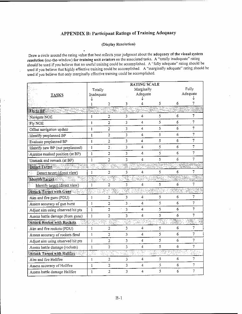
APPENDIX B: Participant Ratings of Training Adequacy
(Display Resolution)
Draw a circle around the rating value that best reflects your judgment about the adequacy of the visual system resolution (out-the-window) for training unit aviators on the associated tasks. A "totally inadequate" rating should be used if you believe that no useful training could be accomplished. A "fully adequate" rating should be used if you believe that highly effective training could be accomplished. A "marginally adequate" rating should be used if you believe that only marginally effective training could be accomplished.
TASKS
RATING SCALE Totally Marginally Fully
Inadequate Adequate Adequate I I i 1 2 3 4 , 5 6 7
FlvtoBP
ÜNavigateNOE 12 3 4 5 6 7
;yFlyNOE 1 2 3 4 5 6 7
-Offset navigation update 1 2 3 4 5 6 7
^Identify preplanned BP 1 2 3 4 5 6 7
nEvaluate preplanned BP 12 3 4 5 6 7
identify new BP (not preplanned) 1 2 3 4 5 6 7
Assume masked position (at BP) 1 2 3 4 5 6 7
■Unmask and remask (at BP) 1 2 3 4 5 6 7
Detect Tar set
.-v Detect target (direct view) 1 2 3 4 5 6 7
IdentifvTarget
Identify tarnet (direct view) 1 2 3 4 5 6 7
Attack Target with Guns
Aim and fire guns (PDU) 12 3 4 5 6 7
: Assess accuracy of gun burst 1 2 3 4 5 6 7
Adjust aim using observed hit pts 1 2 3 4 5 6 7
Assess battle damage (from guns) 1 2 3 4 5 6 7
Attack Rocket with Rockets
Aim and fire rockets (PDU) 1 2 3 4 5 6 7
Assess accuracy of rockets fired 12 3 4 5 6 7
Adjust aim using observed hit pts 12 3 4 5 6 7
Assess battle damage (rockets) 12 3 4 5 6 7
Attack Target with Hellfire
Aim and fire Hellfire 12 3 4 5 6 7
Assess accuracy of Hellfire 12 3 4 5 6 7
Assess battle damage Hellfire 12 3 4 5 6 7
B-l
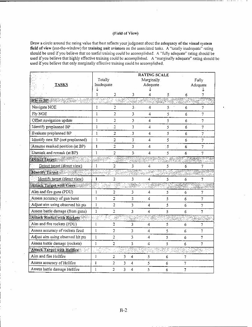
(Field of View)
Draw a circle around the rating value that best reflects your judgment about the adequacy of the visual system field of view (out-the-window) for training unit aviators on the associated tasks. A "totally inadequate" rating should be used if you believe that no useful training could be accomplished. A "fully adequate" rating should be used if you believe that highly effective training could be accomplished. A "marginally adequate" rating should be used if you believe that only marginally effective training could be accomplished.
TASKS
RATING SCALE Totally Marginally Fully
Inadequate Adequate Adequate I I I 1 2 3 4 5 6 7
FIvtoBP
Navigate NOE 1 2 3 4 5 6 7
!,.;FlyNOE 12 3 4 5 6 7
Offset navigation update 1 2 3 4 5 6 7
Identify preplanned BP 12 3 4 5 6 7
Evaluate preplanned BP 1 2 3 4 5 6 7
Identify new BP (not preplanned) 1 2 3 4 5 6 7
Assume masked position (at BP) 1 2 3 4 5 6 7
Ünmask and remask (at BP) 1 2 3 4 5 6 7
'Detect Target
: Detect target (direct view) .1 2 3 4 5 6 7 : Identify Tarnet
Identify tareet (direct view) 1 2 3 4 5 6 7
' Attack Target with Guns
Aim and fire guns (PDU) 12 3 4 5 6 7
.Assess accuracy of gun burst 12 3 4 5 6 7 Adjust aim using observed hit pts 1 2 3 4 5 6 7 Assess battle damage (from guns) 1 2 3 4 5 6 7 Attack Rocket with Rockets
Aim and fire rockets (PDU) 12 3 4 5 6 7 Assess accuracy of rockets fired 12 3 4 5 6 7 Adjust aim using observed hit pts 12 3 4 5 6 7 Assess battle damage (rockets) 12 3 4 5 6 7 Attack Target with Hellfire
Aim and fire Hellfire 1 2 3 4 5 6 7
Assess accuracy of Hellfire 1 2 3 4 5 6 7
Assess battle damage Hellfire 1 2 3 4 5 6 7
B-2