ficha técnica libro de servicio - puricom
TRANSCRIPT
Ficha técnicaLibro de servicio
2 | 4
FT
Data sheetService book

FTÍNDICE
1. CARACTERÍSTICAS PRINCIPALES2. CARACTERÍSTICAS TÉCNICAS3. FUNCIONAMIENTO DEL EQUIPO4. INTERFACE. ESTADO EN EL QUESE ENCUENTRA EL SISTEMA5. GARANTÍA6. HOJA DE REGISTRO DE INSTALACIÓNY PUESTA EN SERVICIO DEL EQUIPO7. LIBRO DE SERVICIO. USUARIO
469
1112
1315
INDEX
1. MAIN FEATURES2. TECHNICAL FEATURES3. HOW THE EQUIPMENT WORKS4. INTERFACE. SYSTEM STATUS5. WARRANTY6. EQUIPMENT INSTALLATION AND INITIAL OPERATION REGISTRATION SHEET7. SERVICE BOOK. USER
1618212324
2527
Espa
ñol
Espa
ñol
4
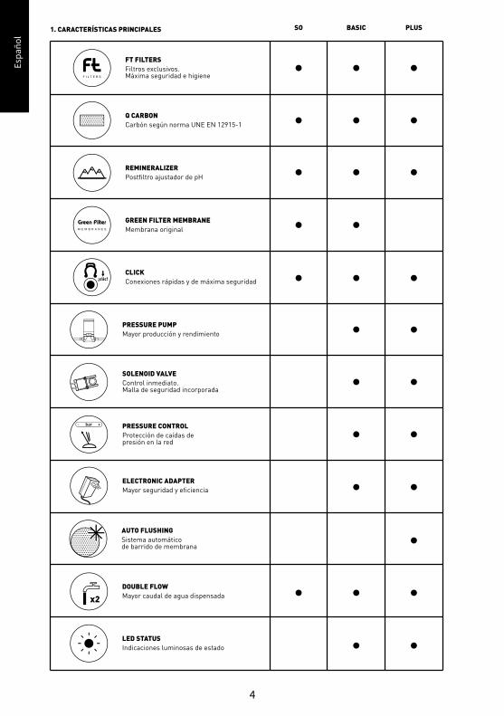
1. CARACTERÍSTICAS PRINCIPALES PLUSBASICSO
PRESSURE PUMPMayor producción y rendimiento
SOLENOID VALVEControl inmediato.Malla de seguridad incorporada
PRESSURE CONTROLProtección de caídas depresión en la red
DOUBLE FLOWMayor caudal de agua dispensada
FT FILTERSFiltros exclusivos.Máxima seguridad e higiene
Q CARBONCarbón según norma UNE EN 12915-1
REMINERALIZERPostfiltro ajustador de pH
GREEN FILTER MEMBRANEMembrana original
CLICKConexiones rápidas y de máxima seguridad
LED STATUSIndicaciones luminosas de estado
ELECTRONIC ADAPTERMayor seguridad y eficiencia
AUTO FLUSHINGSistema automáticode barrido de membrana
Espa
ñol
Espa
ñol
5
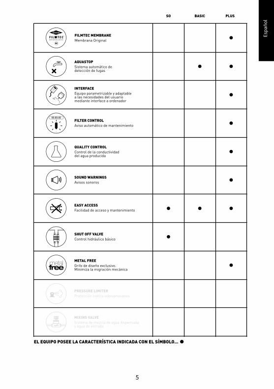
MIXING VALVESistema de mezcla de agua dispensaday agua de entrada
UVSistema bactericida medianteluz ultravioleta
PLUS
METAL FREEGrifo de diseño exclusivo.Minimiza la migración mecánica
AQUASTOPSistema automático dedetección de fugas
INTERFACEEquipo parametrizable y adaptablea las necesidades del usuariomediante interface a ordenador
FILTER CONTROLAviso automático de mantenimiento
QUALITY CONTROLControl de la conductividaddel agua producida
SOUND WARNINGSAvisos sonoros
PRESSURE LIMITERProtección contra sobrepresiones
FILMTEC MEMBRANEMembrana Original
BASICSO
SHUT OFF VALVEControl hidráulico básico
EASY ACCESSFacilidad de acceso y mantenimiento
EL EQUIPO POSEE LA CARACTERÍSTICA INDICADA CON EL SÍMBOLO...
Espa
ñol
Espa
ñol
6
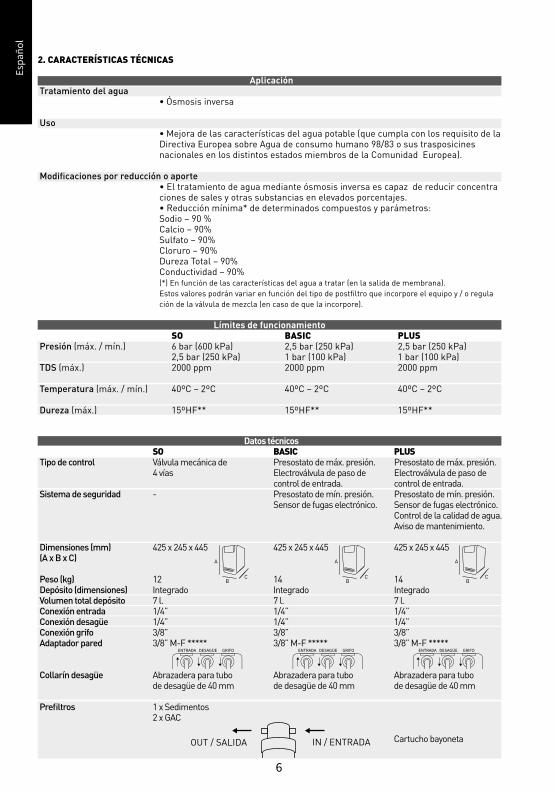
AplicaciónTratamiento del agua • Ósmosis inversa
Uso • Mejora de las características del agua potable (que cumpla con los requisito de la Directiva Europea sobre Agua de consumo humano 98/83 o sus trasposicines nacionales en los distintos estados miembros de la Comunidad Europea).
Modificaciones por reducción o aporte • El tratamiento de agua mediante ósmosis inversa es capaz de reducir concentra ciones de sales y otras substancias en elevados porcentajes. • Reducción mínima* de determinados compuestos y parámetros: Sodio – 90 % Calcio – 90% Sulfato – 90% Cloruro – 90% Dureza Total – 90% Conductividad – 90% (*) En función de las características del agua a tratar (en la salida de membrana). Estos valores podrán variar en función del tipo de postfiltro que incorpore el equipo y / o regula ción de la válvula de mezcla (en caso de que la incorpore).
Datos técnicos SO BASIC PLUSTipo de control Válvula mecánica de Presostato de máx. presión. Presostato de máx. presión. 4 vías Electroválvula de paso de Electroválvula de paso de control de entrada. control de entrada.Sistema de seguridad - Presostato de mín. presión. Presostato de mín. presión. Sensor de fugas electrónico. Sensor de fugas electrónico. Control de la calidad de agua. Aviso de mantenimiento.
Dimensiones (mm) 425 x 245 x 445 425 x 245 x 445 425 x 245 x 445 (A x B x C)
Peso (kg) 12 14 14Depósito (dimensiones) Integrado Integrado IntegradoVolumen total depósito 7 l. 7 l. 7 l.Conexión entrada 1/4” 1/4” 1/4”Conexión desagüe 1/4” 1/4” 1/4”Conexión grifo 3/8” 3/8” 3/8”Adaptador pared 3/8” M-F ***** 3/8” M-F ***** 3/8” M-F *****
Collarín desagüe Abrazadera para tubo Abrazadera para tubo Abrazadera para tubo de desagüe de 40 mm de desagüe de 40 mm de desagüe de 40 mm
Prefiltros 1 x Sedimentos 2 x GAC
Cartucho bayoneta
Límites de funcionamiento SO BASIC PLUSPresión (máx. / mín.) 6 bar (600 kPa) 2,5 bar (250 kPa) 2,5 bar (250 kPa) 2,5 bar (250 kPa) 1 bar (100 kPa) 1 bar (100 kPa)TDS (máx.) 2000 ppm 2000 ppm 2000 ppm
Temperatura (máx. / mín.) 40ºC – 2ºC 40ºC – 2ºC 40ºC – 2ºC
Dureza (máx.) 15ºHF** 15ºHF** 15ºHF**
ENTRADA DESAGÜE GRIFO ENTRADA DESAGÜE GRIFOENTRADA DESAGÜE GRIFO
OUT / SALIDA IN / ENTRADA
A
BC
A
BC
A
BC
2. CARACTERÍSTICAS TÉCNICAS
Espa
ñol
Espa
ñol
7
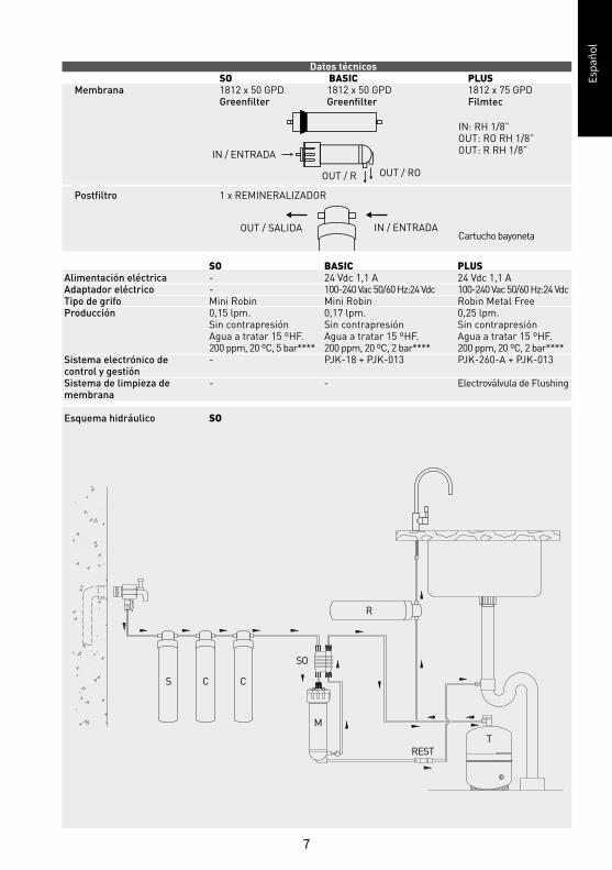
Datos técnicos SO BASIC PLUSMembrana 1812 x 50 GPD 1812 x 50 GPD 1812 x 75 GPD Greenfilter Greenfilter Filmtec
Postfiltro 1 x REMINERALIZADOR
OUT / SALIDA IN / ENTRADA
IN / ENTRADA
OUT / R OUT / RO
Cartucho bayoneta
IN: RH 1/8”OUT: RO RH 1/8”OUT: R RH 1/8”
SO BASIC PLUSAlimentación eléctrica - 24 Vdc 1,1 A 24 Vdc 1,1 AAdaptador eléctrico - 100-240 Vac 50/60 Hz:24 Vdc 100-240 Vac 50/60 Hz:24 Vdc Tipo de grifo Mini Robin Mini Robin Robin Metal FreeProducción 0,15 lpm. 0,17 lpm. 0,25 lpm. Sin contrapresión Sin contrapresión Sin contrapresión Agua a tratar 15 ºHF. Agua a tratar 15 ºHF. Agua a tratar 15 ºHF. 200 ppm, 20 ºC, 5 bar**** 200 ppm, 20 ºC, 2 bar**** 200 ppm, 20 ºC, 2 bar****Sistema electrónico de - PJK-18 + PJK-013 PJK-260-A + PJK-013control y gestiónSistema de limpieza de - - Electroválvula de Flushingmembrana
Esquema hidráulico SO
S C C
M
SO
REST
R
T

Espa
ñol
Espa
ñol
8
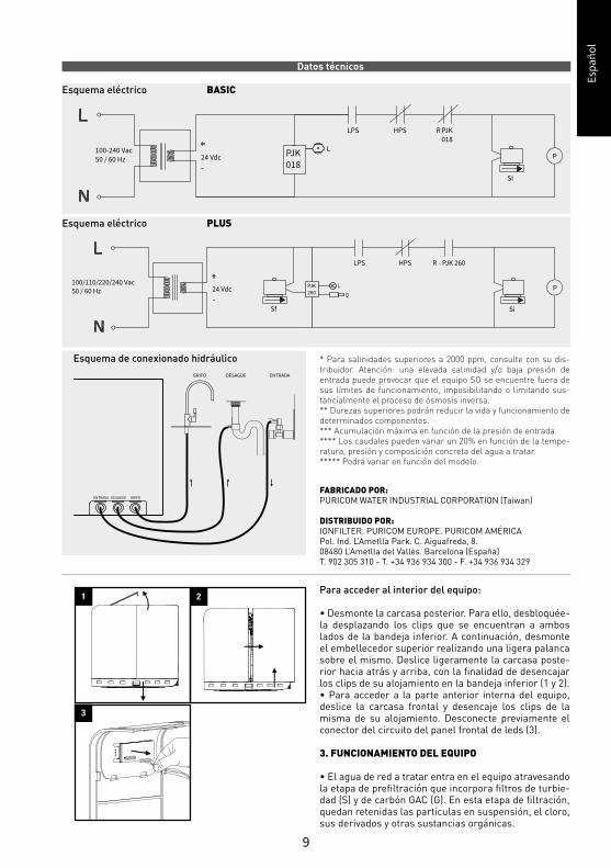
Datos técnicos Esquema hidráulico BASIC
Esquema hidráulico PLUS
S
SiLPS
C
R
G
HPS
P
T
L
M
C
R
S
SiLPS
C C
Espa
ñol
Espa
ñol
9
100/110/220/240 Vac50 / 60 Hz 24 Vdc
LPS HPS
Si
P
R - PJK 260
Sf
PJK260
L
Q
FABRICADO POR:PURICOM WATER INDUSTRIAL CORPORATION (Taiwan)
DISTRIBUIDO POR: IONFILTER. PURICOM EUROPE. PURICOM AMÉRICAPol. Ind. L’Ametlla Park. C. Aiguafreda, 8.08480 L’Ametlla del Vallès. Barcelona (España)T. 902 305 310 - T. +34 936 934 300 - F. +34 936 934 329
Para acceder al interior del equipo:
• Desmonte la carcasa posterior. Para ello, desbloquée-la desplazando los clips que se encuentran a ambos lados de la bandeja inferior. A continuación, desmonte el embellecedor superior realizando una ligera palanca sobre el mismo. Deslice ligeramente la carcasa poste-rior hacia atrás y arriba, con la finalidad de desencajar los clips de su alojamiento en la bandeja inferior (1 y 2).• Para acceder a la parte anterior interna del equipo, deslice la carcasa frontal y desencaje los clips de la misma de su alojamiento. Desconecte previamente el conector del circuito del panel frontal de leds (3).
3. FUNCIONAMIENTO DEL EQUIPO
• El agua de red a tratar entra en el equipo atravesando la etapa de prefiltración que incorpora filtros de turbie-dad (S) y de carbón GAC (G). En esta etapa de filtración, quedan retenidas las partículas en suspensión, el cloro, sus derivados y otras sustancias orgánicas.
* Para salinidades superiores a 2000 ppm, consulte con su dis-tribuidor. Atención: una elevada salinidad y/o baja presión de entrada puede provocar que el equipo SO se encuentre fuera de sus límites de funcionamiento, imposibilitando o limitando sus-tancialmente el proceso de ósmosis inversa.** Durezas superiores podrán reducir la vida y funcionamiento de determinados componentes.*** Acumulación máxima en función de la presión de entrada.**** Los caudales pueden variar un 20% en función de la tempe-ratura, presión y composición concreta del agua a tratar.***** Podrá variar en función del modelo.
ENTRADA DESAGÜE GRIFO
GRIFO DESAGÜE ENTRADA
1 2
3
Datos técnicos Esquema eléctrico BASIC
Esquema eléctrico PLUS
100-240 Vac50 / 60 Hz 24 Vdc PJK
018
L
LPS HPS PJK018
Si
P
R
Esquema de conexionado hidráulico
Espa
ñol
Espa
ñol
10
• El paso del agua hacia el interior del equipo es contro-lado mediante una electroválvula de corte (Si) o válvula mecánica de 4 vías (en función del modelo).
• El agua, tras ser tratada en la etapa de filtración, es impulsada hacia la membrana de ósmosis inversa (M). En función del modelo, el equipo podrá incorporar una bomba (P) para aumentar la presión. La presión del agua sobre la membrana hace posible el proceso de ósmosis inversa.
• El agua osmotizada se almacena en un depósito de acumulación para su posterior consumo. El agua de re-chazo o con exceso de sales y otras sustancias disueltas se dirige hacia el desagüe para su eliminación.
• Los equipos con bomba (BASIC y PLUS) controlan el llenado del depósito mediante un presostato (HPS)
• Al solicitar agua por medio del grifo del equipo, el agua acumulada en el tanque pasa a través de un postfiltro (R) cuya finalidad es la eliminación de posibles olores y sabores, así como ajustar el pH (en función del modelo) que pudiese retener el agua antes de ser dispensada.
• En función del modelo, los equipos incorporan dis-tintos sistemas funcionales y/o de seguridad, gestio-nados por un módulo electrónico de última genera-ción:
• Sistema electrónico de detección de fugas(L). Cuando el sistema detecta esta situación, blo-quea el equipo emitiendo una señal acústica y luminosa informando al respecto. El equipo permanecerá bloqueado hasta que la sonda de detección se encuentre seca.
• Sonda de estimación de la conductividad del agua producida para evaluación del estado en el que se encuentra la membrana y compo-nentes (Q). Al pulsar el botón frontal, el siste-ma realizará una medición de la conductividad del agua producida.
• Aviso automático de cambio de filtros, con objeto de informar al usuario de que se debe realizar el mantenimiento adecuado para ga-rantizar la calidad del agua dispensada. Para garantizar la calidad del agua dispensada, el equipo debe ser mantenido de forma adecua-da.
• El sistema incorpora una válvula automática de limpieza de membrana (Sf), que realizará barridos de la superficie de la misma de forma eficiente y periódica, con objeto de arrastrar los depósitos que se puedan producir sobre la superficie de la misma.
• Los equipos con bomba (BASIC y PLUS) in-corporan un presostato de mínima presión para proteger la bomba ante caídas de presión en la red (LPS).
Espa
ñol
Espa
ñol
11
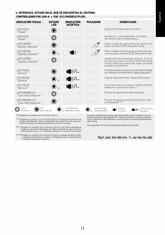
INDICACIÓN ACÚSTICA
4. INTERFACE. ESTADO EN EL QUE SE ENCUENTRA EL SISTEMACONTROLADOR PJK-260-A + PJK -013 (MODELO PLUS)
INDICACIÓN VISUAL
LED AZUL“Power”
LED VERDE“Quality indicator”
LED AZUL“Power”
LED VERDE“Quality indicator”
LED VERDE“Quality indicator”
LED ROJO“Service”
LED ROJO“Service”
LED AMARILLO“Low inlet pressure”
LED ROJO“Service”
LED AMARILLO“Low inlet pressure”
Equipo alimentado eléctricamente.-
-
-
Indica calidad de agua producida óptima tras pulsar el botón PUSH del panel frontal.
Indica calidad reducida de agua producida ópti-ma tras pulsar el botón PUSH del panel frontal.
Sistema de funcionamiento correcto. Si no se ilumina tras pulsar el botón PUSH del panel frontal, existe una alarma de mayor prioridad activada e indicándose.
El mantenimiento necesario / cambio de filtros debe ser realizado inminentemente. Equipo bloqueado. *
Fuga de agua detectada. Equipo Bloqueado. *
Presión de agua de entrada suficiente.
El mantenimiento necesario / cambio de filtros deberá ser realizado en breve. *
Presión de agua de entrada insuficiente. Equi-po bloqueado. ***
Incidencia o funcionamiento incorrecto del sistema eléctrico/electrónico.
PULSADORESTADOLED
SIGNIFICADO
-
-
-
-
-
-
-
-
(*) Póngase en contacto con su Servicio Técnico.
(**) Póngase en contacto con su Servicio Ténico si el equipo no detuviera la producción (llgando a llenar el depósito) tras varias horas de funciona-miento continuo, sin haberse producido extracción de agua.
(***) Póngase en contacto con su Servicio Técnico si de forma reiterada el equipo se encuentra bloqueado por falta de presión de agua de red a la entrada del mismo, y / o habiendo presión en el resto de la vivienda.
(****) Póngase en contacto con su Servicio Técnico si, después de abrir el grifo, el equipo se encontrase en reposo, sin dispensar agua a través del grifo ni mostrar ningún tipo de alarma.
Los avisos acústicos (que podrán estar desactivados según modelo) no son con-tinuados, durando unos segundos (10”). Mientras la alarma continúe indicándo-se por medio de los LEDs del panel, el aviso acústico se emitirá periódicamente cada 7 horas.
Lea el apartado resolución de problemas del Manual de Usuario.
TELF. SAT: 902 305 310 - T. +34 936 934 300
Señales acústicas
Señal acústica periódica
Led no iluminado
Led iluminado fijo x1
Led iluminado parpadeo simple x2
Led iluminado parpadeo doble
x1
x1
x2
-
Espa
ñol
Espa
ñol
12
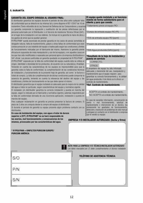
5. GARANTÍA
GARANTÍA DEL EQUIPO DIRIGIDA AL USUARIO FINAL:
EMPRESA Y/O INSTALADOR AUTORIZADO: (fecha y firma)
TELÉFONO DE ASISTENCIA TÉCNICA:S/O
P/N
S/N
El distribuidor garantiza los equipos durante el período de dos años ante cualquier falta de conformidad que se detecte en los mismos tal y como dispone el RD 1/2007 de 16 de noviembre (Texto refundido de la Ley General de Defensa de los Consumidores y usuarios) La garantía comprende la reparación y sustitución de las piezas defectuosas por el personal autorizado por el Distribuidor o el Servicio de Asistencia Técnica Oficial (SAT), en el lugar de la instalación o en sus talleres. Se incluye en la garantía la mano de obra y los gastos de envío que se puedan generar. IF/PEU/PAM* queda exonerado de prestar garantía en los casos de piezas sometidas al desgaste natural, falta de mantenimiento, golpes u otras faltas de conformidad que sean consecuencia de un uso indebido del equipo o inadecuado según las condiciones y límites de funcionamiento indicadas por el fabricante del mismo. Asimismo la garantía pierde eficacia en supuestos de mala manipulación y uso de los equipos, o en aquellos casos en los que han sido modificados o reparados por personal ajeno a la empresa distribuidora o SAT oficial. Las piezas sustituidas en garantía quedarán en propiedad de IF/PEU/PAM*IF/PEU/PAM* responde por la falta de conformidad del equipo cuando ésta se refiera al origen, identidad o idoneidad de los productos, de acuerdo con su naturaleza y finalidad. Teniendo en cuenta las características de los equipos es imprescindible para que la garantía cubra la falta de conformidad, la cumplimentación de las condiciones técnicas de instalación y funcionamiento de la presente hoja de garantía; así como la factura o ticket de compra. La falta de cumplimentación de dichas condiciones puede comportar la ausencia de garantía, teniendo en cuenta la relevancia del destino del equipo y las condiciones y límites de funcionamiento en las que debe operar el mismo.El distribuidor garantiza que el equipo instalado es adecuado para la mejora de la calidad del agua a tratar en particular, según características del equipo y normativa vigente. El instalador y/o distribuidor garantiza la correcta instalación y puesta en marcha del equipo, según lo indicado por el fabricante y normativa vigente y además responderá por la falta de conformidad derivada de una incorrecta aplicación, instalación o puesta en marcha del equipo.Para cualquier reclamación en garantía es preciso presentar la factura de compra. El plazo de 2 años se computa desde la compra del equipo al distribuidor.Si durante el período de garantía su equipo presenta algún problema contacte con su distribuidor.En caso de instalación del equipo, con agua a tratar de durezasuperior a 25ºF, IF/PEU/PAM* no se hará responsable delas averías, mal funcionamiento y consecuencias de losmismos, provocados por las características del agua.
* IF/PEU/PAM = IONFILTER/PURICOM EUROPE/ PURICOM AMÉRICA
El equipo queda instalado y en funciona-miento de forma satisfactoria para el cliente y para que conste:*Tratamiento previo al equipo RO:
*Dureza de entrada equipo RO [ºF]:
*TDS de entrada equipo RO [ppm]:
*Presión de entrada equipo RO [bar]:
*TDS Agua producida (Grifo) [ppm]:
*Resultado de la hoja de instalación y puesta en servicio CORRECTO.
OTROS: El propietario del equipo ha sido informado adecuada y claramente del uso, manipulación y mantenimiento que el equipo requiere para garantizar su correcto funcionamiento y la calidad del agua producida. A tal efecto se le ofrece un contrato de mantenimiento. *Ref. Contrato de mantenimiento
ACEPTA el contrato de mantenimiento. NO ACEPTA el contrato de mantenimiento.
En caso de necesitar información, comunicación de avería o mal funcionamiento, solicitud de mantenimiento o intervención de un técnico, lea previamente los apartados de funcionamiento, detección y resolución de problemas de este manual y póngase en contacto con el distribuidor o empresa que le vendió su equipo.
Espa
ñol
Espa
ñol
13
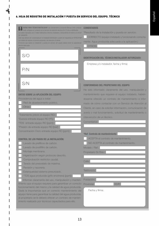
6. HOJA DE REGISTRO DE INSTALACIÓN Y PUESTA EN SERVICIO DEL EQUIPO. TÉCNICO
HOJA A CUMPLIMENTAR POR EL TÉCNICO INSTALADOR. HOJA PARA EL TÉCNICO INSTALADOR.
HOJA DEL REGISTRO DE INSTALACIÓN Y PUESTA EN SERVICIO DEL EQUIPO
NOTAS PARA TÉCNICO/INSTALADOR: Lea atentamente el presente Manual. Ante cualquier duda, póngase en contacto con el servicio de atención técnica (S.A.T.) de su distribuidor.
Los datos marcados con (*) debe rellenarlos el técnico instalador y transcribirlos él mismo a la HOJA DE GARANTÍA.Esta hoja deberá ser conservada por el instalador/distribuidor y podrá ser requerida por IF/PEU/PAM*, con objeto de mejorar el servicio postventa y de atención al cliente.El técnico que realice la instalación y puesta en servicio del equipo deberá tener la capacitación técnica adecuada.
S/O
P/N
S/N
COMENTARIOS
*Resultado de la instalación y puesta en servicio:
CORRECTO (equipo instalado y funcionando correcta-
mente. Agua producida adecuada a la aplicación.)
OTROS:
IDENTIFICACIÓN DEL TÉCNICO/INSTALADOR AUTORIZADO:
Empresa y/o instalador, fecha y firma:
CONFORMIDAD DEL PROPIETARIO DEL EQUIPO:
He sido informado claramente del uso, manipulación y
mantenimiento que requiere el equipo instalado, habién-
doseme ofrecido un contrato de mantenimiento e infor-
mado de cómo contactar con un Servicio de Atención al
Cliente, en caso de solicitar información, comunicación de
avería o mal funcinamiento, solicitud de mantenimiento o
intervención de un técnico.
Comentarios
*Ref. Contrato de mantenimiento
ACEPTA el contrato de mantenimiento.
NO ACEPTA el contrato de mantenimiento.
Modelo / Ref.:
Propietario Sr./Sra.:
Calle:
Teléfono/s:
Población:
Provincia: C.P:
Fecha y firma:
DATOS SOBRE LA APLICACIÓN DEL EQUIPO:
Procedencia del agua a tratar:
Red de abastecimiento público.
Otras:
*Tratamiento previo al equipo RO:
*Dureza entrada equipo RO [ºF]:
*TDS entrada equipo RO [ppm]:
*Presión de entrada equipo RO [bar]:
Concentración Cloro entrada equipo RO [ppm]:
CONTROL DE LOS PASOS DE LA INSTALACIÓN:
Lavado de prefiltros de carbón.
Lavado de postfiltro de carbón.
Montaje membrana.
Higienización según protocolo descrito.
Comprobación restrictor caudal.
Tarado del presostato de máxima.
Revisión y racorería.
Estanqueidad sistema presurizado.
*TDS agua producida (grifo encimera) [ppm]:
Informar claramente del uso, manipulación y manten-imiento que el equipo requiere para garantizar un correcto funcionamiento del mismo y la calidad de agua producida. Dada la importancia que un correcto mantenimiento del equipo tiene para garantizar la calidad del agua producida, al propietario se le deberá ofrecer un contrato de manten-imiento realizado por técnicos capacitados para ello.
Espa
ñol
Espa
ñol
14
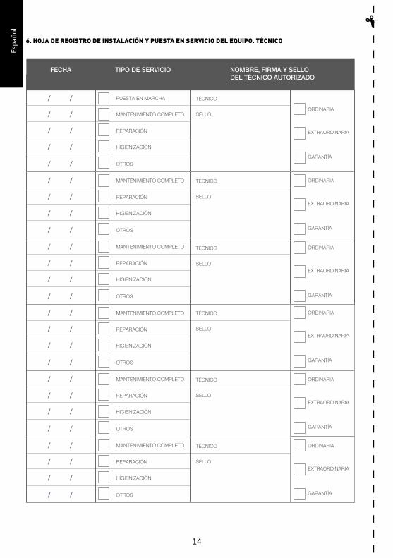
6. HOJA DE REGISTRO DE INSTALACIÓN Y PUESTA EN SERVICIO DEL EQUIPO. TÉCNICO
MANTENIMIENTO COMPLETO
REPARACIÓN
HIGIENIZACIÓN
OTROS
/ /
/ /
/ /
/ /
MANTENIMIENTO COMPLETO
REPARACIÓN
HIGIENIZACIÓN
OTROS
/ /
/ /
/ /
/ /
MANTENIMIENTO COMPLETO
REPARACIÓN
HIGIENIZACIÓN
OTROS
/ /
/ /
/ /
/ /
MANTENIMIENTO COMPLETO
REPARACIÓN
HIGIENIZACIÓN
OTROS
/ /
/ /
/ /
/ /
MANTENIMIENTO COMPLETO
REPARACIÓN
HIGIENIZACIÓN
OTROS
/ /
/ /
/ /
/ /
TIPO DE SERVICIOFECHA NOMBRE, FIRMA Y SELLODEL TÉCNICO AUTORIZADO
MANTENIMIENTO COMPLETO
REPARACIÓN
HIGIENIZACIÓN
OTROS
/ /
PUESTA EN MARCHA/ /
/ /
/ /
/ /
TÉCNICO
ORDINARIA
EXTRAORDINARIA
GARANTÍA
SELLO
TÉCNICO ORDINARIA
EXTRAORDINARIA
GARANTÍA
SELLO
TÉCNICO ORDINARIA
EXTRAORDINARIA
GARANTÍA
SELLO
TÉCNICO ORDINARIA
EXTRAORDINARIA
GARANTÍA
SELLO
TÉCNICO ORDINARIA
EXTRAORDINARIA
GARANTÍA
SELLO
TÉCNICO ORDINARIA
EXTRAORDINARIA
GARANTÍA
SELLO
Espa
ñol
Espa
ñol
15
7. LIBRO DE SERVICIO. USUARIO
MANTENIMIENTO COMPLETO
REPARACIÓN
HIGIENIZACIÓN
OTROS
/ /
/ /
/ /
/ /
MANTENIMIENTO COMPLETO
REPARACIÓN
HIGIENIZACIÓN
OTROS
/ /
/ /
/ /
/ /
MANTENIMIENTO COMPLETO
REPARACIÓN
HIGIENIZACIÓN
OTROS
/ /
/ /
/ /
/ /
MANTENIMIENTO COMPLETO
REPARACIÓN
HIGIENIZACIÓN
OTROS
/ /
/ /
/ /
/ /
MANTENIMIENTO COMPLETO
REPARACIÓN
HIGIENIZACIÓN
OTROS
/ /
/ /
/ /
/ /
TIPO DE SERVICIOFECHA NOMBRE, FIRMA Y SELLODEL TÉCNICO AUTORIZADO
MANTENIMIENTO COMPLETO
REPARACIÓN
HIGIENIZACIÓN
OTROS
/ /
PUESTA EN MARCHA/ /
/ /
/ /
/ /
TÉCNICO
ORDINARIA
EXTRAORDINARIA
GARANTÍA
SELLO
TÉCNICO ORDINARIA
EXTRAORDINARIA
GARANTÍA
SELLO
TÉCNICO ORDINARIA
EXTRAORDINARIA
GARANTÍA
SELLO
TÉCNICO ORDINARIA
EXTRAORDINARIA
GARANTÍA
SELLO
TÉCNICO ORDINARIA
EXTRAORDINARIA
GARANTÍA
SELLO
TÉCNICO ORDINARIA
EXTRAORDINARIA
GARANTÍA
SELLO
Engl
ish
16
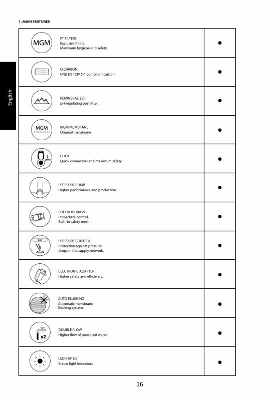
1. MAIN FEATURES
PRESSURE PUMPHigher performance and production.
SOLENOID VALVEImmediate control.Built-in safety mesh.
PRESSURE CONTROLProtection against pressuredrops in the supply network.
DOUBLE FLOWHigher �ow of produced water.
FT FILTERSExclusive �lters. Maximum hygiene and safety.
Q CARBONUNE EN 12915-1 compliant carbon.
REMINERALIZERpH-regulating post-�lter.
MGM MEMBRANEOriginal membrane
CLICKQuick connectors and maximum safety.
LED STATUSStatus light indicators.
ELECTRONIC ADAPTERHigher safety and e�ciency.
AUTO FLUSHINGAutomatic membrane�ushing system.
Engl
ish
17
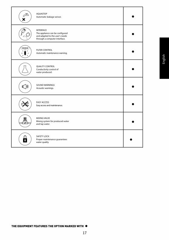
MIXING VALVEMixing system for produced waterand tap water.
AQUASTOPAutomatic leakage sensor.
INTERFACEThe appliance can be con�gured and adapted to the user's needsthrough a computer interface.
FILTER CONTROLAutomatic maintenance warning.
QUALITY CONTROLConductivity control ofwater produced.
SOUND WARNINGSAcoustic warnings.
EASY ACCESSEasy access and maintenance.
SAFETY LOCKProper maintenance guarantees water quality
THE EQUIPMENT FEATURES THE OPTION MARKED WITH
Engl
ish
18
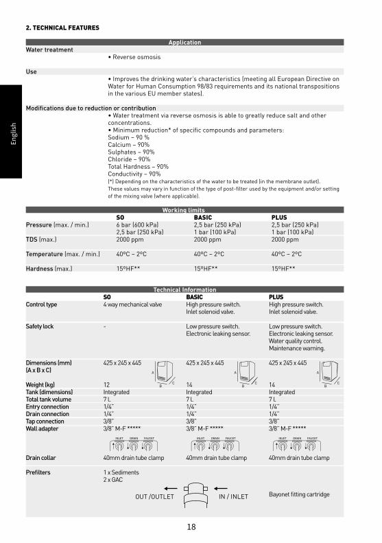
2. TECHNICAL FEATURES
Application Water treatment • Reverse osmosis
Use • Improves the drinking water’s characteristics (meeting all European Directive on Water for Human Consumption 98/83 requirements and its national transpositions in the various EU member states).
Modifications due to reduction or contribution • Water treatment via reverse osmosis is able to greatly reduce salt and other concentrations. • Minimum reduction* of specific compounds and parameters: Sodium – 90 % Calcium – 90% Sulphates – 90% Chloride – 90% Total Hardness – 90% Conductivity – 90% (*) Depending on the characteristics of the water to be treated (in the membrane outlet). These values may vary in function of the type of post-filter used by the equipment and/or setting of the mixing valve (where applicable).
Working limits SO BASIC PLUSPressure (max. / min.) 6 bar (600 kPa) 2,5 bar (250 kPa) 2,5 bar (250 kPa) 2,5 bar (250 kPa) 1 bar (100 kPa) 1 bar (100 kPa)TDS (max.) 2000 ppm 2000 ppm 2000 ppm
Temperature (max. / min.) 40ºC – 2ºC 40ºC – 2ºC 40ºC – 2ºC
Hardness (max.) 15ºHF** 15ºHF** 15ºHF**
Technical Information SO BASIC PLUSControl type 4 way mechanical valve High pressure switch. High pressure switch. Inlet solenoid valve. Inlet solenoid valve. Safety lock - Low pressure switch. Low pressure switch. Electronic leaking sensor. Electronic leaking sensor. Water quality control. Maintenance warning.
Dimensions (mm) 425 x 245 x 445 425 x 245 x 445 425 x 245 x 445 (A x B x C)
Weight (kg) 12 14 14Tank (dimensions) Integrated Integrated IntegratedTotal tank volume 7 l. 7 l. 7 l.Entry connection 1/4” 1/4” 1/4”Drain connection 1/4” 1/4” 1/4”Tap connection 3/8” 3/8” 3/8”Wall adapter 3/8” M-F ***** 3/8” M-F ***** 3/8” M-F *****
Drain collar 40mm drain tube clamp 40mm drain tube clamp 40mm drain tube clamp
Prefilters 1 x Sediments 2 x GAC Bayonet fitting cartridgeOUT /OUTLET IN / INLET
A
BC
A
BC
A
BC
INLET DRAIN FAUCET INLET DRAIN FAUCET INLET DRAIN FAUCET
Engl
ish
19
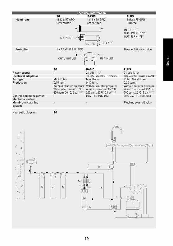
Technical Information SO BASIC PLUSMembrane 1812 x 50 GPD 1812 x 50 GPD 1812 x 75 GPD Greenfilter Greenfilter Filmtec
Post-filter 1 x REMINERALIZER
OUT / OUTLET IN / INLET
IN / INLET
OUT / R OUT / RO
IN: RH 1/8”OUT: RO RH 1/8”OUT: R RH 1/8”
SO BASIC PLUSPower supply - 24 Vdc 1,1 A 24 Vdc 1,1 AElectrical adaptator - 100-240 Vac 50/60 Hz:24 Vdc 100-240 Vac 50/60 Hz:24 Vdc Tap type Mini Robin Mini Robin Robin Metal FreeProduction 0,15 lpm. 0,17 lpm. 0,25 lpm. Without counter pressure Without counter pressure Without counter pressure Water to be treated 15 ºHF. Water to be treated 15 ºHF. Water to be treated 15 ºHF. 200 ppm, 20 ºC, 5 bar**** 200 ppm, 20 ºC, 2 bar**** 200 ppm, 20 ºC, 2 bar****Control and management - PJK-18 + PJK-013 PJK-260-A + PJK-013electronic systemMembrane cleaning - - Flushing solenoid valvesystem
Hydraulic diagram SO
S C C
M
SO
REST
R
T
Bayonet fitting cartridge
Engl
ish
20
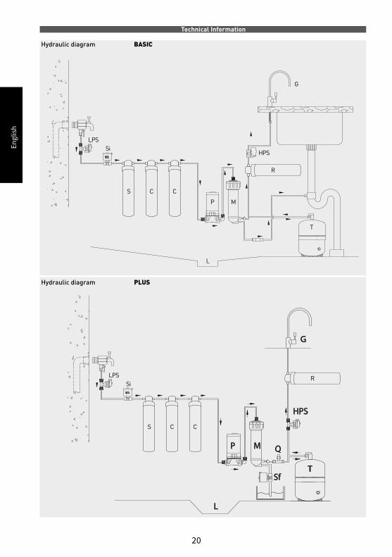
Technical Information Hydraulic diagram BASIC
Hydraulic diagram PLUS
S
SiLPS
C
R
G
HPS
P
T
L
M
C
R
S
SiLPS
C C
Engl
ish
21
100/110/220/240 Vac50 / 60 Hz 24 Vdc
LPS HPS
Si
P
R - PJK 260
Sf
PJK260
L
Q
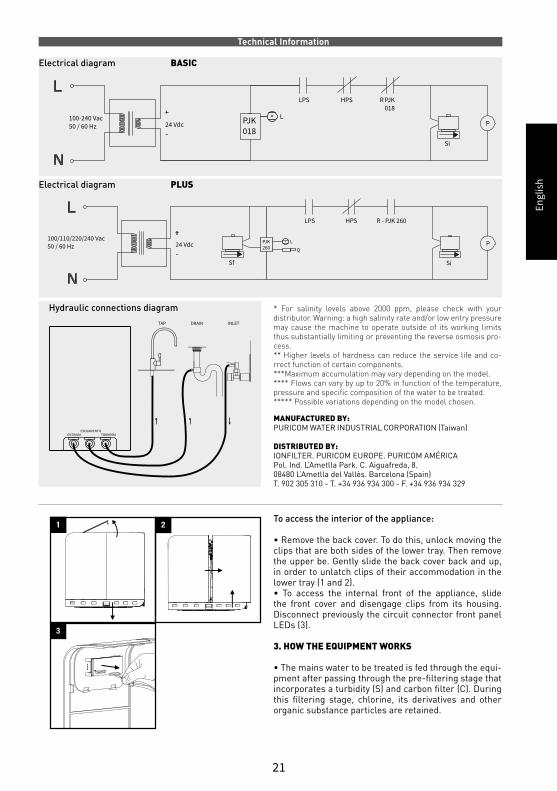
MANUFACTURED BY: PURICOM WATER INDUSTRIAL CORPORATION (Taiwan) DISTRIBUTED BY: IONFILTER. PURICOM EUROPE. PURICOM AMÉRICA Pol. Ind. L’Ametlla Park. C. Aiguafreda, 8. 08480 L’Ametlla del Vallès. Barcelona (Spain) T. 902 305 310 - T. +34 936 934 300 - F. +34 936 934 329
To access the interior of the appliance:
• Remove the back cover. To do this, unlock moving the clips that are both sides of the lower tray. Then remove the upper be. Gently slide the back cover back and up, in order to unlatch clips of their accommodation in the lower tray (1 and 2).• To access the internal front of the appliance, slide the front cover and disengage clips from its housing. Disconnect previously the circuit connector front panel LEDs (3).
3. HOW THE EQUIPMENT WORKS
• The mains water to be treated is fed through the equi-pment after passing through the pre-filtering sta ge that incorporates a turbidity (S) and carbon filter (C). During this filtering stage, chlorine, its derivatives and other organic substance particles are retained.
* For salinity levels above 2000 ppm, please check with your distribu tor. Warning: a high salinity rate and/or low entry pressure may cause the machine to operate outside of its working limits thus substantially limiting or preventing the reverse osmosis pro-cess. ** Higher levels of hardness can reduce the service life and co-rrect function of certain components. ***Maximum accumulation may vary depending on the model. **** Flows can vary by up to 20% in function of the temperature, pres sure and specific composition of the water to be treated. ***** Possible variations depending on the model chosen.
ENTRADAESCOAMENTO
TORNEIRA
TAP DRAIN INLET
1 2
3
Technical Information Electrical diagram BASIC
Electrical diagram PLUS
100-240 Vac50 / 60 Hz 24 Vdc PJK
018
L
LPS HPS PJK018
Si
P
R
Hydraulic connections diagram
Engl
ish
22
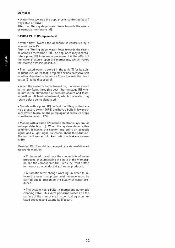
SO model
• Water flow towards the appliance is controlled by a 4 ways shut off valve After the filtering stage, water flows towards the rever-se osmosis membrane (M).
BASIC & PLUS (Pump models)
• Water flow towards the appliance is controlled by a solenoid valve (Si) After the filtering stage, water flows towards the rever-se osmosis membrane (M). The appliance may incorpo-rate a pump (P) to increase pressure. It is the effect of the water pressure upon the membrane, which makes the reverse osmo sis possible.
• The treated water is stored in the tank (T) for its sub-sequent use. Water that is rejected or has excessive salt or other dissolved substances flows towards the drain outlet (G) to be disposed of.
• When the system’s tap is turned on, the water sto red in the tank flows through a post-filtering stage (R) who-se aim is the elimination of possible odours and taste, as well as pH level adjustment, which the water may retain before being dispensed.
• Models with a pump (P) control the fi lling of the tank via a pressure switch (HPS) and have a built-in low pres-sure switch to protect the pump against pres sure drops from the network (LPS).
• Models with a pump (P) include electronic system for leakage detection (L). When the system detects this condition, it blocks the system and emits an acoustic signal and a light signal to in form about the situation. The unit will remain blocked until the leakage sensor is dry.
Besides, PLUS model is managed by a state-of-the-art electronic module:
• Probe used to estimate the conductivity of water produced, thus assessing the state of the membra-ne and the components (Q). Press the front button to me asure the conductivity of water produced.
• Automatic filter change warning, in order to in-form the user that proper maintenance must be carried out to guarantee the quality of water pro-duced.
• The system has a build-in membrane automatic cleaning valve. This valve performs sweeps on the surface of the membrane in order to drag accumu-lated deposits and extend its lifespan.

Engl
ish
23
ACOUSTIC INDICATION
4. INTERFACE. SYSTEM STATUS
VISUAL INDICATION
BLUE LED“Power”
GREEN LED“Quality indicator”
BLUE LED“Power”
GREEN LED“Quality indicator”
GREEN LED“Quality indicator”
RED LED“Service”
RED LED“Service”
YELLOW LED“Low inlet pressure”
RED LED“Service”
YELLOW LED“Low inlet pressure”
Electrically powered system.-
-
-
When the PUSH-button on the front panel is pressed, it indicates that the quality of water produced is excellent.When the PUSH-button on the front panel is pressed, it indicates that the quality of water produced is poor.When the PUSH-button on the front panel is pressed, No light indicates good water but some more important alarm is on.
Carry out the maintenance/change the filters im-mediately. *
A water leak has been detected. System bloc-ked.Remove water from sensor in order to start back the unit. *
Sufficient water pressure input .
Carry out the maintenance/change the filters soon.
Insufficient water pressure input . System blocked.*
The electric/electronic system is not wor-king properly/has failed.*
PUSH BUTTON
STATUS LED
MEANING
-
-
-
-
-
-
-
-
[*] Contact your service.
(**)When you detect any of the states described abo ve, contact with the maintenance service to arrange appointment. See the relevant section in the Manual Technical.
(***) Contact your service if the unit blocks repeatedly due to low water pres-sure and having pressure water on the rest of the house.
(****) Contact your service if , after opening the faucet, the unit would find at rest, without dispensing water using the tap or showing any alarm.
The beeps are not continuous; they last a few seconds (10 “). While maintenance state is maintained it will be indicated by LEDs on the panel and acoustic notifica-tion periodically every 7 hours.
Read troubleshooting section in User Manual.
TELF. SAT: 902 305 310 - T. +34 93 693 43 00
Acoustic signals
Regular acous-tic signal
LED is off
LED is per-manently on x1
LED is on: single flashing x2
LED is on: dou-ble flashing
x1
x1
x2
-
Engl
ish
24
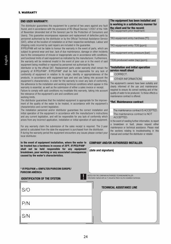
5. WARRANTY
END USER WARRANTY:
COMPANY AND/OR AUTHORISED INSTALLER:
(date and signature)
TECHNICAL ASSISTANCE LINES/O
P/N
S/N
* IF/PEU/PAM = IONFILTER/PURICOM EUROPE/ PURICOM AMÉRICA
The equipment has been installed and is working in a satisfactory manner for the client and for the record:
*RO equipment prior treatment:
*RO equipment entry hardness [ºF]:
*RO equipment entry TDS [ppm]:
*RO equipment entry pressure [bar]:
*TDS produced water (tap) [ppm]:
*Installation and initial operation service result sheet CORRECT.
OTHER INFORMATION:
*Ref. Maintenance contract
The maintenance contract IS ACCEPTED. The maintenance contract is NOT
ACCEPTED.
NOTES FOR THE COMPANY/AUTHORISED TECHNICIAN/INSTALLER:Information marked with an (*) should be filled in by the installation technician.IDENTIFICATION OF THE SYSTEM:
The distributor guarantees this equipment for a period of two years against any fault found, and in accordance with the provisions of RD (Royal Decree) 1/2007 of the 16th of November (Amended text of the General Law for the Protection of Consumers and Users). This guarantee encompasses reparaion and replacement of defective parts by personnel authorised by the distributor or by the Official Technical Assistance Service (SAT), either at the location of installation or at their respective workshops. Labour and shipping costs incurred by said repairs are included in the guarantee. IF/PEU/PAM will not be liable to honour the warranty in the event of parts, which are subject to general wear and tear, lack of due maintenance, damage or other incidents due to the consequence of misuse or inappropriate use in accordance with conditions, and functional limits of said equipment as indicated by the manufacturer. Furthermore, the warranty will be rendered invalid in the event of poor use or in the event of said equipment being modified or repaired by personnel not authorised by the distributor or by the official SAT. Replacement parts under warranty shall remain the property of IF/PEU/PAM*. IF/PEU/PAM* shall be held responsible for any lack of conformity of equipment in relation to its origin, identity or appropriateness of the products, in accordance with equipment type and end use.Taking into account the equipment’s characteristics, in order for the warranty to cover any lack of conformity, the adherence to the installation and working technical conditions which appear in this warranty is essential, as well as the submission of either a sales invoice or receipt. Failure to comply with said conditions my invalidate this warranty, taking into account the relevance of the equipment’s aim and conditions and working limits. The distributor guarantees that the installed equipment is appropriate for the improve-ment of the quality of the water to be treated, in accordance with the equipment’s characteristics and current legislation. The installation personnel and/or distributor guarantees the correct installation and initial operation of the equipment in accordance with the manufacturer’s instructions and any current legislation, and will be responsible for any lack of conformity which arises from any incorrect application, installation or initial operation of said equipment.
For any warranty claim the submission of the sales receipt is required. The 2-year period is calculated from the date the equipment is purchased from the distributor. If during the warranty period the equipment encounters any issues please contact your local distributor.
In the event of equipment installation, where the water to be treated has a hardness in excess of 25ºF, IF/PEU/PAM*shall not be held responsible for any equipment breakdown, poor working or any associated consequences caused by the water’s characteristics.
In the event of needing further information, to report a breakdown or fault, please request either maintenance or technical assistance. Please read the sections relating to troubleshooting in this manual and contact the distributor or retailer.
The equipment’s owners have been suitably and clearly informed of the use and maintenance required to ensure its correct working and of the quality of water to be produced. To these effects a maintenance contract is offered.
Engl
ish
25
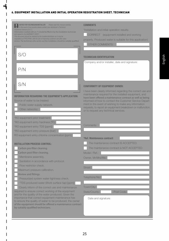
6. EQUIPMENT INSTALLATION AND INITIAL OPERATION REGISTRATION SHEET. TECHNICIAN
NOTES FOR TECHNICIAN/INSTALLER: Please read this manual carefully.
S/O
P/N
S/N
COMMENTS
*Installation and initial operation results:
CORRECT (equipment installed and working
properly. Produced water is suitable for this application)
OTHER COMMENTS:
TECHNICIAN IDENTIFICATION
Company and/or installer, date and signature:
CONFORMITY OF EQUIPMENT OWNER:
I have been clearly informed regarding the correct use and maintenance required for the installed equipment, and
informed of how to contact the Customer Service Depart-ment in the event of wishing to make any information requests, to report an equipment breakdown or malfunction, or to request any technical services.
Comments
*Ref. Maintenance contract:
The maintenance contract IS ACCEPTED.
The maintenance contract is NOT ACCEPTED.
Model / Ref.:
Owner, Mr/Mrs/Ms:
Street:
Telephone No:
Town/City:
State/County: Post Code:
Date and signature:
INFORMATION REGARDING THE EQUIPMENT’S APPLICATION:
Source of water to be treated:
Public water supply network.
Other networks:
*RO equipment prior treatment:
*RO equipment entry hardness [ºF]:
*RO equipment entry TDS [ppm]:
*RO equipment entry pressure [bar]:
RO equipment entry chlorine concentration [ppm]:
INSTALLATION PROCESS CONTROL:
Membrane assembly.
Sanitation in accordance with protocol.
Flow restrictor check.
Maximum pressure calibration.
Pressurized system water tightness check.
*TDS produced water (Work surface tap) [ppm]:
Clearly inform of the correct use and maintenance required to ensure correct working of the equipment and for the quality of the water produced. Given the importance that correct equipment maintenance has to ensure the quality of water to be produced, the owner
In the event of any queries please contact your distributor’s Technical Assistance Service (S.A.T.).
and copied to the WARRANTY SHEET. This document should be retained by the installer/distributor as it may be requested by IF/PEU/PAM, with the aim of improving customer and after sales
Engl
ish
26
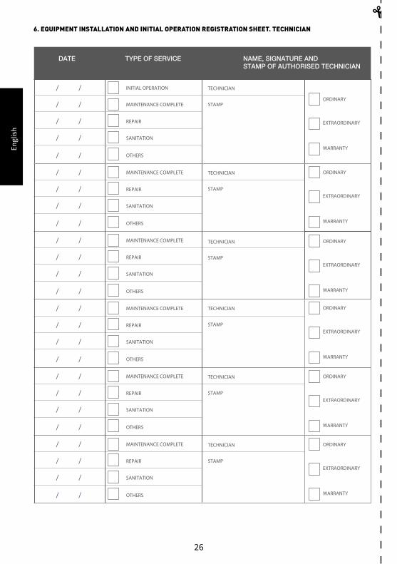
6. EQUIPMENT INSTALLATION AND INITIAL OPERATION REGISTRATION SHEET. TECHNICIAN
MAINTENANCE COMPLETE
REPAIR
SANITATION
OTHERS
/ /
/ /
/ /
/ /
MAINTENANCE COMPLETE
REPAIR
SANITATION
OTHERS
/ /
/ /
/ /
/ /
MAINTENANCE COMPLETE
REPAIR
SANITATION
OTHERS
/ /
/ /
/ /
/ /
MAINTENANCE COMPLETE
REPAIR
SANITATION
OTHERS
/ /
/ /
/ /
/ /
MAINTENANCE COMPLETE
REPAIR
SANITATION
OTHERS
/ /
/ /
/ /
/ /
TYPE OF SERVICEDATE NAME, SIGNATURE ANDSTAMP OF AUTHORISED TECHNICIAN
MAINTENANCE COMPLETE
REPAIR
SANITATION
OTHERS
/ /
INITIAL OPERATION/ /
/ /
/ /
/ /
TECHNICIAN
ORDINARY
EXTRAORDINARY
WARRANTY
STAMP
TECHNICIAN ORDINARY
EXTRAORDINARY
WARRANTY
STAMP
TECHNICIAN ORDINARY
EXTRAORDINARY
WARRANTY
STAMP
TECHNICIAN ORDINARY
EXTRAORDINARY
WARRANTY
STAMP
TECHNICIAN ORDINARY
EXTRAORDINARY
WARRANTY
STAMP
TECHNICIAN ORDINARY
EXTRAORDINARY
WARRANTY
STAMP
Engl
ish
27
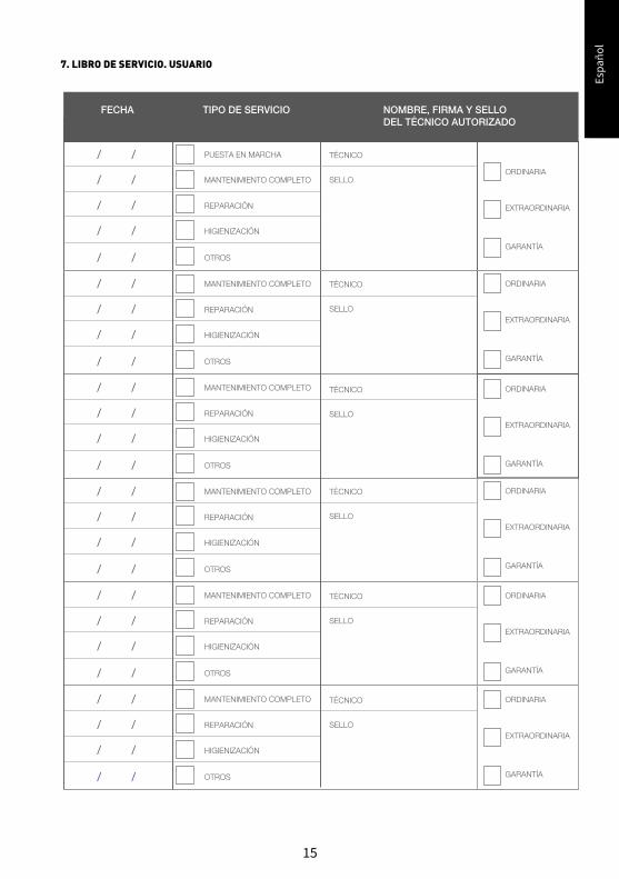
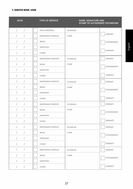
7. SERVICE BOOK. USER
MAINTENANCE COMPLETE
REPAIR
SANITATION
OTHERS
/ /
/ /
/ /
/ /
MAINTENANCE COMPLETE
REPAIR
SANITATION
OTHERS
/ /
/ /
/ /
/ /
MAINTENANCE COMPLETE
REPAIR
SANITATION
OTHERS
/ /
/ /
/ /
/ /
MAINTENANCE COMPLETE
REPAIR
SANITATION
OTHERS
/ /
/ /
/ /
/ /
MAINTENANCE COMPLETE
REPAIR
SANITATION
OTHERS
/ /
/ /
/ /
/ /
TYPE OF SERVICEDATE NAME, SIGNATURE ANDSTAMP OF AUTHORISED TECHNICIAN
MAINTENANCE COMPLETE
REPAIR
SANITATION
OTHERS
/ /
INITIAL OPERATION/ /
/ /
/ /
/ /
TECHNICIAN
ORDINARY
EXTRAORDINARY
WARRANTY
STAMP
TECHNICIAN ORDINARY
EXTRAORDINARY
WARRANTY
STAMP
TECHNICIAN ORDINARY
EXTRAORDINARY
WARRANTY
STAMP
TECHNICIAN ORDINARY
EXTRAORDINARY
WARRANTY
STAMP
TECHNICIAN ORDINARY
EXTRAORDINARY
WARRANTY
STAMP
TECHNICIAN ORDINARY
EXTRAORDINARY
WARRANTY
STAMP

FTALISON2016
FT