fiber tracker update edward mckigney imperial college july 3 rd, 2002
TRANSCRIPT

Fiber Tracker Update
Edward McKigney
Imperial College
Imperial College July 3rd, 2002
Outline
• Fiber Tracker Description
• Near-term R&D Program
• Tentative Milestones
• Summary

Emittance Measurement(P. Janot)
Fiber Tracker
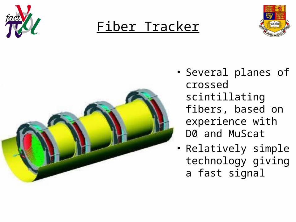
• Several planes of crossed scintillating fibers, based on experience with D0 and MuScat
• Relatively simple technology giving a fast signal

Fiber Tracker Layout
• Layout based on 0.35 mm or 0.50 mm round doubly clad fibers with a doublet layer structure
• Three layers of doublets crossed at 120º provide an active area of 30 cm diameter
• There are a total of 4286 (3000) fibers per detector plane
• 0.3% (0.4%) X0 per plane with a resolution of about 40 m (extrapolated from the measured resolution in D0)
(A. Bross)
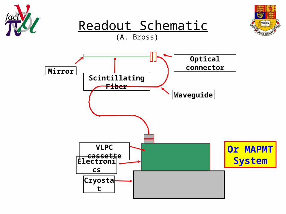
Readout Schematic
MirrorScintillating
Fiber
Optical connector
Waveguide
VLPC cassette
Electronics
Cryostat
Or MAPMTSystem
(A. Bross)

VLPC
• VLPC (Visible Light Photon Counter)– Cryogenic APD
operating @ 9K
• Characterization/test/sort Cassette Assignment– As shown
(A. Bross)

VLPC Performance(A. Bross)
• VLPC HISTE VI– High QE 80%
– Low noise <5X10⁴ Hz (@1.0 pe)
– High Rate capability
• >40 MHz
– High production yield 70% (vs. 27% projected)

Important Detector Issues
• Detectors must operate in strong solenoidal fields & with intense RF-cavity backgrounds & contribute negligible emittance degradation
• Working out safe design and operating approaches is a crucial and challenging part of the MUCOOL R&D effort underway at Fermilab

Front-End Electronics
• Current VLPC readout uses SVXII chip, this is being replaced by D0
• New electronics will be clocked at 132 nS, and are being designed now; based on a custom ASIC(TriP chip) and commercial ADC and FPGA chips
• Need to evaluate if these electronics can be used for MICE
• If we can use the D0 electronics, we just need to order them when D0 does its production, if not new electronics will be a major undertaking

Near Term R&D
• Prototypes of two versions (.35 mm and .5 mm) of the SciFi ribbons are being made at FNAL – these are 1 inch ribbons with no adhesive in the active region (‘stretched fiber’ design)
• A test cryostat with 32 VLPC channels is being constructed at FNAL
• A beam test with muons at KEK will happen in the Autumn
• Tests with the 805 MHz cavity in FNAL Lab G will happen before Christmas
Conclusions
• We have a good conceptual design based on round scintillating fibers and VLPC readout
• Suitability of the new D0 readout electronics needs to be determined
• Prototypes are being constructed now, and will be tested in a muon beam and with an 805 MHz RF cavity
• The RF background issue needs to be resolved using a 201 MHZ cavity
• There is a good deal of mechanical design work, probably 1-2 years FTE