fhwa project r05 iap funded project case study: texas ... · texas precast concrete pavement...
TRANSCRIPT
FHWA REPORT NO. FHWA-HIF-17-017
FHWA PROJECT R05 IAP FUNDED PROJECT CASE STUDY
TEXAS PRECAST CONCRETE PAVEMENT
INTERSECTION DEMONSTRATION PROJECT
December 2016

Notice This document is disseminated under the sponsorship of the U.S. Department of Transportation in the interest of information exchange. The U.S. Government assumes no liability for the use of the information contained in this document. The U.S. Government does not endorse products or manufacturers. Trademarks or manufacturers' names appear in this report only because they are considered essential to the objective of the document.
Quality Assurance Statement The Federal Highway Administration (FHWA) provides high-quality information to serve Government, industry, and the public in a manner that promotes public understanding. Standards and policies are used to ensure and maximize the quality, objectivity, utility, and integrity of its information. FHWA periodically reviews quality issues and adjusts its programs and processes to ensure continuous quality improvement.
1. Report No. FHWA-HIF-17-017
2. Government Accession No
3. Recipient’s Catalog No
3. Title and Subtitle FHWA Project R05 IAP Funded Project Case Study: Texas Precast Concrete Pavement Intersection Demonstration Project
5. Report Date December 2016 6. Performing Organization Code
7. Authors Shiraz Tayabji, Ph.D., P.E., and Wouter Brink, Ph.D.
8. Performing Organization Report No.
9. Performing Organization Name and Address Applied Research Associates, Inc. 100 Trade Centre Drive, Suite 200 Champaign, IL 61820
10. Work Unit No. (TRAIS) C6B 11. Contract or Grant No.
DTFH61-13-C-00028 12. Sponsoring Agency Name and Address
Office of Infrastructure Federal Highway Administration 1200 New Jersey Avenue, SE Washington, DC 20590
13. Type of Report and Period Covered Final Report
March 2015 – December 2016 14. Sponsoring Agency Code
Project No. 1983
15. Supplementary Notes Contracting Officer’s Representative: Sam Tyson, P.E. 16. Abstract The production use of precast concrete pavement (PCP) has come a long way over the last 15 years. The technology is gaining wider acceptance in the U.S. for rapid repair and rehabilitation of concrete pavements as well as for heavily trafficked asphalt concrete pavements and intersections. Several U.S. highway agencies, including Caltrans, Illinois Tollway, and the New Jersey, New York, and Utah State Departments of Transportation, have implemented the PCP technology, and other agencies have constructed demonstration projects. In the U.S., the PCP technology is being used on concrete pavements for intermittent repairs (full-depth joint repairs or full panel replacement) and for continuous applications (longer length/wider area rehabilitation) with service life expectations of at least 20 years for intermittent repairs and at least 40 years for continuous applications, without significant future corrective treatment. The use of PCP on asphalt pavements includes the replacement of ramps, intersections and bus pads. The Strategic Highway Research Program 2 (SHRP2) Project R05 was conducted from 2008 to 2012 to develop technical information and guidelines that would encourage the rapid and successful adoption of PCP technology. In 2013, the SHRP2 Implementation Assistance Program (IAP) was created to help State DOTs, metropolitan planning organizations, and other interested organizations deploy SHRP2-developed products to deliver more efficient, cost-effective solutions to meet the complex challenges facing transportation agencies. On March 28, 2014, the Federal Highway Administration—in partnership with the American Association of State Highway and Transportation Officials—announced the selection of several transportation agencies receiving implementation and technical assistance awards as part of round 3 of the SHRP2 IAP. The Texas Department of Transportation, one of the agencies selected as a lead adopter of Project R05 technology, received an award of $300,000 to help offset the cost of constructing a PCP project. This case study report provides details of the 2016 PCP use for rehabilitation of a distressed asphalt concrete pavement at the intersection of Route 97 and Route 72 in McMullen/LaSalle County, Texas. 17. Key Words Intersection rehabilitation, precast concrete pavement system, construction, pavement rehabilitation, SHRP2, SHRP2 Project R05
18. Distribution Statement No restriction.
Security Classification (of this report): Unclassified
19. Security Classification (of this page): Unclassified
20. No. of Pages 33
21. Price
Form DOT F 1700.7 (8-72) Reproduction of completed page authorized

ii
TABLE OF CONTENTS
INTRODUCTION ........................................................................................................................ 1
SHRP2 PROJECT R05 BACKGROUND .......................................................................................................... 1
SHRP2 PROJECT R05 PRODUCT IMPLEMENTATION PROGRAM ...................................................... 2
PROJECT DETAILS ................................................................................................................... 3
PROJECT DESCRIPTION ................................................................................................................................. 3
PAVEMENT DETAILS ....................................................................................................................................... 7
PRECAST CONCRETE PAVEMENT SYSTEM DETAILS .......................................................................... 8
CONSTRUCTION STAGING AND TRAFFIC-RELATED REQUIREMENTS ........................................ 12
PANEL FABRICATION ................................................................................................................................... 13
PANEL INSTALLATION ................................................................................................................................. 15
SUMMARY AND LESSONS LEARNED ................................................................................ 25
ACKNOWLEDGMENTS .......................................................................................................... 27
iii
LIST OF FIGURES Figure 1. Map. Project location. ...................................................................................................... 3 Figure 2. Photo. Layout of the existing AC intersection. ............................................................... 4 Figure 3. Photo. A view of the AC intersection before rehabilitation. ........................................... 4 Figure 4. Diagram. Panel layout at intersection. ............................................................................. 5 Figure 5. Diagram. Detailed view of the panel layout along SH 97. .............................................. 6 Figure 6. Diagram. Detailed view of the panel layout along SH 72. .............................................. 6 Figure 7. Diagram. Joint load transfer scheme. .............................................................................. 9 Figure 8. Photo. View of a typical panel. ....................................................................................... 9 Figure 9. Photo. View of a typical panel with dowel bars ready to be placed in the ducts. ......... 10 Figure 10. Photo. View of a dowel placed in the duct and resting on a mini-chair. ..................... 10 Figure 11. Diagram. Three stages of panel installation. ............................................................... 13 Figure 12. Photo. Panel formwork setup. ..................................................................................... 14 Figure 13. Photo. Concrete placement in the panel formwork. .................................................... 14 Figure 14. Photo. AC base layer. .................................................................................................. 15 Figure 15. Photo. Panel being moved from the staging area using a backhoe. ............................ 16 Figure 16. Photo. A panel being placed on the AC base. ............................................................. 16 Figure 17. Photo. Panels being aligned with panel location markings on the AC base. .............. 17 Figure 18. Photo. Engaging of the leveling lift system................................................................. 17 Figure 19. Photo. Dowel bar positioning in ducts of adjoining panels. ........................................ 18 Figure 20. Photo. Grout being injected into the adjoining dowel bar ducts and open slots. ........ 18 Figure 21. Photo. Use of pea gravel at the open slots. .................................................................. 19 Figure 22. Photo. Completed grout placement along a joint. ....................................................... 19 Figure 23. Photos. Formwork for the cast-in-place transition slabs. ............................................ 20 Figure 24. Photos. Views of completed transition areas. .............................................................. 20 Figure 25. Photo. A sawed and sealed joint (December 8, 2016). ................................................ 21 Figure 26. Photo. Stage 1 panel installation along SH 97. ........................................................... 21 Figure 27. Photo. Completed intersection (December 8, 2016). .................................................. 22 Figure 28. Photo. Completed intersection in use – view from SH 97 (December 8, 2016). ........ 22 Figure 29. Photo. Completed intersection in use – view from SH 72 (December 8, 2016). ........ 23
LIST OF TABLES Table 1. Key panel geometry tolerances. ...................................................................................... 13

iv
MODERN METRIC CONVERSION FACTORS Conversion factors both to and from the modern metric International System of Units (SI) can be found at: http://www.fhwa.dot.gov/publications/convtabl.cfm.

v
ABBREVIATIONS AND ACRONYMS AASHTO American Association of State Highway and Transportation Officials AC Asphalt concrete DOT Department of Transportation FHWA Federal Highway Administration FWD Falling weight deflectometer IAP Implementation Assistance Program P1, P2, P3 Panel types (1, 2, and 3) PCP Precast concrete pavement RWD Rolling wheel deflectometer SHRP2 Strategic Highway Research Program 2 TxDOT Texas Department of Transportation

vi
1
INTRODUCTION
The production use of precast concrete pavement (PCP) has come a long way over the last 15 years. The technology is gaining wider acceptance in the U.S. for rapid repair and rehabilitation of concrete pavements as well as for heavily trafficked asphalt concrete pavements and intersections. Several U.S. highway agencies, including Caltrans, Illinois Tollway, and the New Jersey, New York, and Utah State Departments of Transportation (DOTs), have implemented the PCP technology, and other agencies have constructed demonstration projects. There have also been many advances in the design, panel fabrication, and panel installation aspects of the PCP technology. In the U.S., the PCP technology is being used on concrete pavements for intermittent repairs (full-depth joint repairs or full panel replacement) and for continuous applications (longer length/wider area rehabilitation) with service life expectations of at least 20 years for intermittent repairs and at least 40 years for continuous applications, without significant future corrective treatment. The use of PCP on asphalt pavements includes the replacement of ramps, intersections and bus pads. PCP technology can significantly reduce traffic impacts of roadway repair and reconstruction projects, particularly on heavily traveled routes. The technology is applicable to small segments, enabling flexibility in construction phasing, as well as for use in corridor-wide pavement reconstruction. SHRP2 PROJECT R05 BACKGROUND Because the information on PCP technology was not well documented, in 2007 the Strategic Highway Research Program 2 (SHRP2) initiated Project R05 to develop the necessary technical information and guidelines that would encourage the rapid and successful adoption of this new technology. The Project R05 study was conducted from 2008 to 2012. The final report, Precast Concrete Pavement Technology, is available at http://www.trb.org/main/blurbs/167788.aspx. The study demonstrated that the PCP technology is ready for wider implementation and that many of the PCP systems available in the U.S. can meet the needs of highway agencies for rapid renewal of their highway systems. The following products were developed under SHRP2 Project R05:
• Overall findings related to viability of the PCP technology. • Findings based on SHRP2 field testing. • Guidelines for PCP project selection. • Guidelines for PCP system acceptance. • Guidelines for design of PCP systems. • Guidelines for PCP fabrication. • Guidelines for PCP installation. • Implementation plan for PCP technology. • Long-term monitoring plan for PCP projects. • Model specifications.

2
The review of projects constructed in the U.S. and the SHRP2 field testing indicated that sufficient advances have been made to reliably design and construct PCP systems to achieve five key attributes of successful pavements, as follows:
• Constructability—Techniques and equipment are available to ensure acceptable production rates for the installation of PCP systems.
• Concrete durability—Plant fabrication of precast panels results in excellent concrete strength and durability.
• Load transfer at joints—Reliable and economical techniques are available to provide effective load transfer at transverse joints in jointed PCP systems and post-tensioned PCP systems.
• Panel support—Techniques to provide adequate and uniform base support conditions continue to be improved.
• Efficiency—Panels are thinner than standard cast-in-place concrete and last longer because of prestressing and/or reinforcing elements in the PCP system.
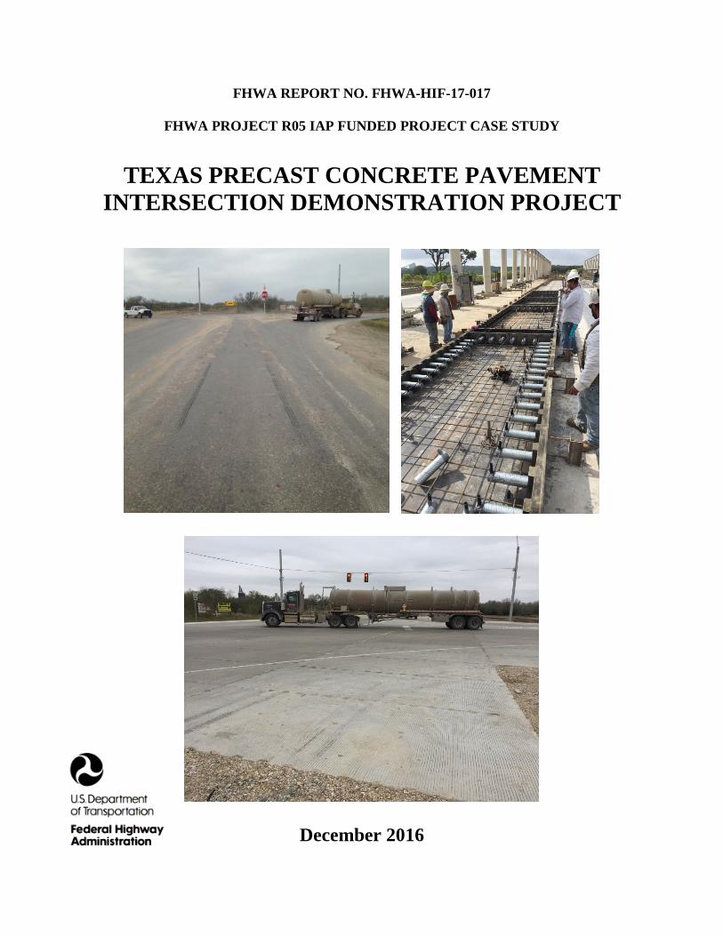
SHRP2 PROJECT R05 PRODUCT IMPLEMENTATION PROGRAM In 2013, the Federal Highway Administration (FHWA) and the American Association of State Highway and Transportation Officials (AASHTO) created the SHRP2 Implementation Assistance Program (IAP) to help State DOTs, metropolitan planning organizations, and other interested organizations deploy SHRP2-developed products to deliver more efficient, cost-effective solutions to meet the complex challenges facing transportation agencies. Seven rounds of the IAP were offered between February 2013 and April 2016. On March 28, 2014, as part of round 3 of the IAP, four lead adopters were selected to receive financial support from the FHWA for implementation of PCP technology. The Texas Department of Transportation (TxDOT), one of the agencies selected as a lead adopter, received an award of $300,000 to help offset the cost of the implementation of PCP technology in the State. The objective of the award was to allow TxDOT to construct a demonstration project that would provide a learning environment for operations such as fabricating panels, setting panels, installing dowel bars, grouting under panel areas, and other related activities needed to implement precast panel installations in Texas. This case study report provides details of the PCP implementation to rehabilitate a distressed asphalt concrete (AC) pavement at the intersection of SH 97 and SH 72 in McMullen/LaSalle County near Fowlerton, Texas. The precast panels were installed between March and June 2016.

3
PROJECT DETAILS PROJECT DESCRIPTION The Eagle Ford Shale in South Texas is the site of one of the biggest energy booms in the U.S. Since 2008, several thousand oil and gas wells have been drilled at this site, and several oil and gas production facilities have been constructed in nearby areas. All of these activities have resulted in heavy truck and construction vehicle traffic along many regional highways that were originally designed for use by farm-to-market traffic. The use of heavy vehicles along these highways has resulted in significant damage to the AC pavements. The principal mode of damage is excessive rutting and delamination of AC layers. Many intersections along these highways have also experienced excessive rutting, requiring frequent maintenance to keep the intersections operational. TxDOT has been investigating techniques to rehabilitate the intersections rapidly that would also result in long-lasting treatments. In early 2015, TxDOT initiated an internal study to evaluate using PCP technology to rapidly rehabilitate damaged AC intersections. TxDOT had constructed a post-tensioned PCP demonstration project in Georgetown in 2001. This project, along a section of a frontage road of I-35, was constructed successfully and has performed well. In early 2015, TxDOT received an award of $300,000 to help offset the cost of implementing PCP technology in the State. TxDOT chose to apply the award funds toward rehabilitating the SH 97 and SH 72 intersection near Fowlerton, shown in figure 1. It was anticipated that if the intersection rehabilitation using PCP was successful, the technique would be applied to rehabilitate similarly distressed AC intersections and damaged AC roadway sections in the energy sector areas.
Figure 1. Map. Project location.

4
The project site is a three-way intersection (T-intersection), with SH 97 as the through highway and SH 72 meeting SH 97 at a right angle. Figure 2 is an aerial photograph of the intersection. SH 97 and SH 72 both have two lanes at the intersection, and there are exit ramps from SH 97 to SH 72 and from SH 72 to SH 97. Figure 3 shows the condition of the intersection before the rehabilitation work.
Figure 2. Photo. Layout of the existing AC intersection.
Figure 3. Photo. A view of the AC intersection before rehabilitation.
TxDOT developed generic plans and specifications for use of PCP at the intersection. The plans called for using a jointed PCP and the panels to be pretensioned during fabrication. The specifications allowed the contractor to propose a PCP system. After preliminary discussions with a supplier of a proprietary PCP system, the contractor proposed using a generic system

5
developed in-house. After several iterations, the contractor proposed the following PCP system and rehabilitation process:
1. Removal of the existing distressed AC pavement at the intersection. 2. Placement of a cement-treated subbase. 3. Placement of a hot-mixed AC base. 4. Placement of the panels.
a. Three types of panels to be used, as shown in figures 5 and 6. b. Panels to be prestressed. c. A generic panel leveling system to be used that would also serve as a panel lifting
insert. d. Panels to be placed directly on the AC base and elevation adjusted, as necessary,
using the leveling system. e. Panels to be undersealed. f. Load transfer to be incorporated at all interior joints. A custom-developed load
transfer system using dowel bars to be used. Figure 4 shows the precast panel layout for the intersection. Figure 5 shows a detailed view of the panel layout for a section of SH 97, and figure 6 provides a detailed view of the panel layout along the SH 72 terminus.
Figure 4. Diagram. Panel layout at intersection.

6
Figure 5. Diagram. Detailed view of the panel layout along SH 97.
Figure 6. Diagram. Detailed view of the panel layout along SH 72.

7
The project details are as follows:
• Project owner: TxDOT. • TxDOT Project No.: STP 2014 (65). • Project plans and specifications prepared by: TxDOT. • Prime contractor: Curran Contracting Company, Converse, Texas. • Panel precaster: Bexar Concrete Works I, Ltd., San Antonio, Texas. • Shop drawing support for Bexar: Unintech Consulting Engineers, Inc., San Antonio,
Texas. • Panel leveling lifts: Generic full-depth lift inset and plate. • Dowel duct grout:
o Phase 1 installation: FastPatch 5000 rapid setting mortar distributed by KLP Commercial, extended with pea gravel in the open slots only.
o Phase 2 and phase 3 installations: SikaQuick 1000 repair mortar, used as a neat formulation.
• Panel undersealing grout: Cement slurry. PAVEMENT DETAILS The details of the intersection rehabilitation are as follows:
• Intersection size: 3,552 square yards. • Existing pavement: Two-course surface treatment over 6 inches of AC base and 9 inches
of cement-treated subgrade • New subbase: Cement-treated subbase. • New base: 4 inches thick hot-mixed AC. • Panels to be placed directly on the AC base and panel elevation to be adjusted, if
necessary, using the built-in leveling lifts. • Total number of precast panels installed: 235.
o Panel thickness: 12 inches. o Panels prestressed along the longer dimension.
• SH 97 panels. o Total length: 312 feet. o Panel type 1 (P1).
Total number: 78. Width: 18 feet. Length: 8 feet.
o Panel type 2 (P2). Total number: 39. Width: 12 feet. Length: 8 feet.
• SH 72 panels. o Total length: 144 feet. o Width: 56 to 264 feet. o Panel type 3 (P3).

8
Total number: 116. Width: 8 feet. Length: 18 feet.
• Transition slabs at each AC and PCP interface along SH 97 and SH 72: o Cast-in-place reinforced concrete. o Tapered longitudinal cross-section to facilitate the transition from and to the
existing AC pavement. • Joint load transfer:
o Length: 14-inch-long dowel bars. o Dowel bar diameter: 1.50 inches. o Dowel bar spacing: 12 inches along interior sides (two to four sides). o Dowel bar positioning within the dowel bar duct: Using mini support chairs.
• Dowel bar slot grout: o To meet requirements of TxDOT DMS 4655 Type A-2 material:
A minimum compressive strength of 3,000 psi in 8 hours. A minimum compressive strength of 4,000 psi at 3 days. Can be used in neat or extended formulation.
• Lifting/leveling system: Dayton Superior T1 single pickup insert, 1 inch in diameter, or equal; leveling plate to be 3/16 inch thick by 4 inches by 4 inches in plan.
• Panel undersealing grout: Cement slurry. • Finishing activity:
o Mill approaches and departures area AC pavement and place new AC surface to match the PCP grade at the transition slabs.
o Install panel anchors at the outside perimeter panels. PRECAST CONCRETE PAVEMENT SYSTEM DETAILS As indicated previously, TxDOT developed generic plans and specifications for use of PCP at the intersection, and the plans called for use of a jointed PCP. The specifications allowed the contractor to propose a PCP system. After preliminary discussions with a supplier of a proprietary PCP system and discussions with TxDOT, the contractor proposed using a generic PCP system developed in-house. Prestressed Precast Panels Three types of panels, designated as P1, P2, and P3, were used. P1 and P2 were used along the SH 97 portion of the intersection, and P3 was used along the SH 72 portion of the intersection. P1 and P3 are essentially the same, except for the direction of carpet drag and tining at the surface because of the orientation of the panels within the intersection. All panels are 8 feet in one dimension; P1 and P3 are 18 feet in the other dimension, and P2 is 12 feet in the other dimension. All panels were prestressed along the long dimension. While most of the panel design details were reasonably of a standard nature, the panels incorporated one-of-a-kind dowel bar ducts to house the dowel bars during panel placement. The dowel bar duct design is a refinement of the narrow-mouth dowel bar slot design developed under the SHRP2 Project R05 study and successfully used by the Illinois Tollway. Instead of the

9
narrow-mouth slots, the contractor and the precaster developed a scheme using a circular corrugated duct, 3-5/8 inches in diameter and 16 inches long, to house the 14-inch-long dowel bars, as shown in figure 7. The design incorporates mini-chairs to position the dowels and a 2-inch-wide open mouth at the joint faces to allow for moving the dowel bars from the panel housing the bars into the companion circular duct in the adjacent panel. The concept was to slide dowel bars into the duct just before a slab was placed over the AC base and then slide half of the dowel-bar length into the adjacent panel after all panels have been placed and before the rapid-setting grout material was introduced into the ducts through the open mouths at the joint face. Figure 8 shows a typical panel with the open mouths along the panel sides, and figure 9 shows a view of a panel with dowel bars ready to be placed in the ducts. Figure 10 shows a view of a dowel placed in the duct and resting on a mini-chair.
Figure 7. Diagram. Joint load transfer scheme.
Figure 8. Photo. View of a typical panel.

10
Figure 9. Photo. View of a typical panel with dowel bars ready to be placed in the ducts.
Figure 10. Photo. View of a dowel placed in the duct and resting on a mini-chair.
The precast panels incorporate the following key features:
• Top and bottom panel reinforcement in both directions. • Pretensioning in the long direction using three ½-inch diameter 7-wire strands. • Concrete strength: Minimum release compressive strength is 3,500 psi; minimum 28-day
compressive strength is 5,000 psi. • Corrugated dowel bar ducts along all sides. • Four lifting/leveling inserts and leveling plates. • Panel undersealing grout ports. • Carpet-drag texture followed by tining.

11
Dowel Bar Duct Grout The project specification required the use of a concrete repair material meeting the requirements of DMS 4655, “Concrete Repair Materials,” Type A-2 category (rapid repair materials) to fill the dowel ducts. The requirements for the Type A materials include the following:
• Minimum compressive strength at 8 hours: 3,000 psi. • Minimum compressive strength at 3 days: 4,000 psi. • Maximum shrinkage: 0.07 percent at 28 days. • Minimum bond strength: 2,000 psi at 3 days. • Can be used as:
o Neat: Material with 100 percent of the final product passing the No. 8 sieve. o Extended: Material with aggregate of the final product retained on the 3/8-inch
sieve. For the phase 1 panel placement, the TxDOT specified use of the FastPatch 5000 rapid setting mortar distributed by KLP Commercial. For phases 2 and 3, the contractor used SikaQuick 1000 repair mortar. Panel Installation The following are the installation steps for the PCP system as specified by TxDOT:
1. Remove existing AC pavement. 2. Install the precast panels over either the existing base material or a new asphaltic or
cementitious material as shown on the plans. Establish grade control for placement of the base material to ensure long-wavelength roughness is not built into the base. Establish grade control using stringlines, laser guidance, or other comparable methods. Ensure that the variation of the base surface will be such that a 6-inch-diameter circular plate, 1/8 inches thick, cannot be passed beneath a 20-foot straightedge.
3. Install panels one at a time over the base. Align the centerline of the panels to a line laid out by a surveyor (provided by the contractor) on the surface of the base prior to placement of the panels. Place panels to the following tolerances:
a. Place the centerline of all precast panels to within 1/4 inch of the pre-surveyed centerline marked on the surface of the base.
b. Match the centerline of adjoining panels to within 1/8 inch of each other at the adjoining edge.
c. Ensure that the top surface of an individual panel is no more than 3/16 inch higher or lower than the top surface of an adjoining panel at any point along the joint between the panels.
d. Ensure that the width of the gap between adjoining panels at the top surface of the joint is no more than 1/4 inch.
4. Install dowel bars on support chairs in the ducts along the interior side of each panel. Leave dowel bar ducts along the matching side of the adjoining panel empty. After an adjoining panel is placed, slide half of the length of the dowel bars into the empty companion dowel bar ducts.
12
5. Adjust the elevation of a panel using the leveling lifts, as needed, to meet the panel placement tolerances.
6. After a group of panels are placed, use a concrete grout material meeting the requirements of DMS 4655, “Concrete Repair Materials,” Type A-2 category to fill the dowel bar ducts and the open slots. Mix, place, and cure the grout material according to the manufacturer’s recommendations.
7. After all panels in a group are placed, perform underslab grouting to fill voids that may be present beneath the panels.
8. After all panels are placed, install end-slab anchors as shown on the plans to tie the perimeter panels to the base and the subbase.
9. Perform finishing activities including surface grinding as directed by TxDOT field staff. The contractor elected to use cast-in place reinforced concrete slabs at all transitions from the existing AC pavement to the PCP. The transition slabs were tapered to accommodate AC surfacing across half the length of the transition slabs. CONSTRUCTION STAGING AND TRAFFIC-RELATED REQUIREMENTS The project specification required the contractor to complete all panel installation work, including existing pavement removal, in a weekend closure beginning at 7:00 pm on a Friday and ending by 5:00 am the following Monday. Any traffic detour construction work was to be completed prior to the weekend closure. The length of a one-way traffic control section was limited to 1/2 mile. The original plans included the construction of detour roads. However, it was decided at the initial pre-construction meetings that a staged construction would be adequate to managed the traffic and at the same time reduce the overall project cost. The panel installation work was performed in three stages, as follows:
• Phase 1: Panels were installed on SH 97 along the outer two panel lanes, for a panel installation width of 30 feet, using panel types P1 and P2.
• Phase 2: Panels were installed at the northern half of the rest of the intersection, consisting of the 18-foot-wide remaining panel lane (P1 along SH 97 and P3 along the SH 72 portion of the intersection).
• Phase 3: Panels were installed at the remaining southern half of the intersection, consisting of the 18-foot wide remaining panel lane (P1 along SH 97 and P3 along the SH 72 portion of the intersection).
The panel installation staging is shown in figure 11. Before the field installation work started, TxDOT conducted extensive public awareness activities. Local detours and one-way operations through the construction areas were manned by the contractor’s construction traffic-management personnel.

13
Figure 11. Diagram. Three stages of panel installation.
PANEL FABRICATION The panels were fabricated during 2015 at the Bexar precast plant in San Antonio. The three panel types were fabricated based on shop drawings prepared by Unintech Consulting Engineers and approved by TxDOT. All panels were rectangular in shape, as discussed previously. The panels were required to meet the key tolerances given in table 1.
Table 1. Key panel geometry tolerances. Dimension Tolerance
Length +/- 1/4 inch Width +/- 1/4 inch Thickness +/- 1/4 inch
Edge Squareness 1/8 inch in 12 inches in relation to top and bottom surfaces
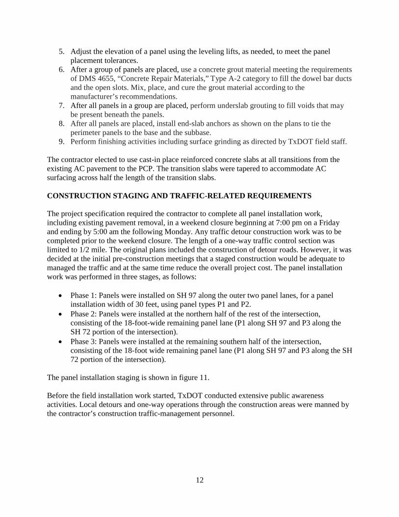
As part of the panel fabrication process, the central-mixed concrete was regularly tested for fresh properties and for strength. The concrete typically exceeded the design compressive strength of 5,000 psi at 28 days and typically exceeded 3,500 psi at time of the prestressing strand release. The panels were fabricated in an outdoor prestressing casting bed. Figure 12 shows a view of the panel formwork set up with the corrugated ducts, two layers of reinforcement, prestressing strands, and lifting/leveling inserts. Figure 13 shows concrete placement in the panel formwork. After the concrete was placed, a carpet drag was applied over the panel surface, followed by tining. When the concrete reached the required strength of 3,500 psi, the strands were de-tensioned and later snipped off from each panel. The panels were cured and stored at the facility
14
and were delivered to staging areas at the intersection a few days before panel installation for each stage.
Figure 12. Photo. Panel formwork setup.
Figure 13. Photo. Concrete placement in the panel formwork.
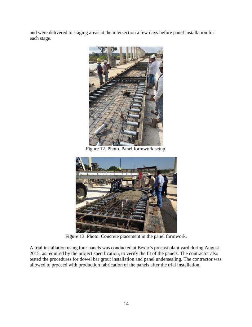
A trial installation using four panels was conducted at Bexar’s precast plant yard during August 2015, as required by the project specification, to verify the fit of the panels. The contractor also tested the procedures for dowel bar grout installation and panel undersealing. The contractor was allowed to proceed with production fabrication of the panels after the trial installation.

15
PANEL INSTALLATION The panels were installed during the spring of 2016, as follows:
• Stage 1 installation: 78 panels along SH 97 during March and April 2016. o Four days of installation. o Panels installed per day: 18, 14, 22, and 24.
• Stage 2 installation: 68 panels installed along SH 97 and SH 72 during May 2016. o Three days of installation. o Panels installed per day: 34, 9, and 25.
• Stage 3 installation: 89 panels installed along SH 97 and SH 72 during June 2016. o Three days of installation. o Panels installed per day: 42, 16, and 31.
The panel installation process for each phase was as follows:
1. Remove existing AC pavement. 2. Cement-treat 6 inches of subgrade. 3. Place a 4-inch-thick hot-mix AC base. Finish base grading to meet base surface tolerance
requirement. Figure 14 shows the AC base layer and checking for surface smoothness.
Figure 14. Photo. AC base layer.
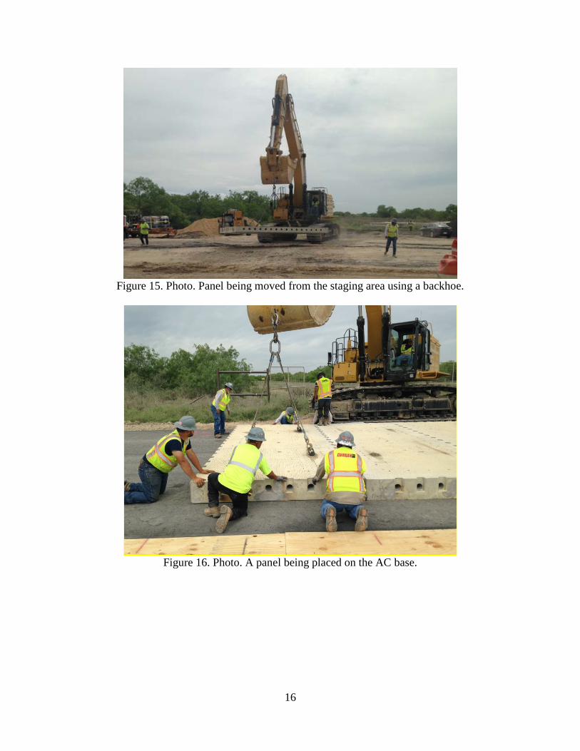
4. Place the panels. The panels were lifted from the staging area at the intersection to the
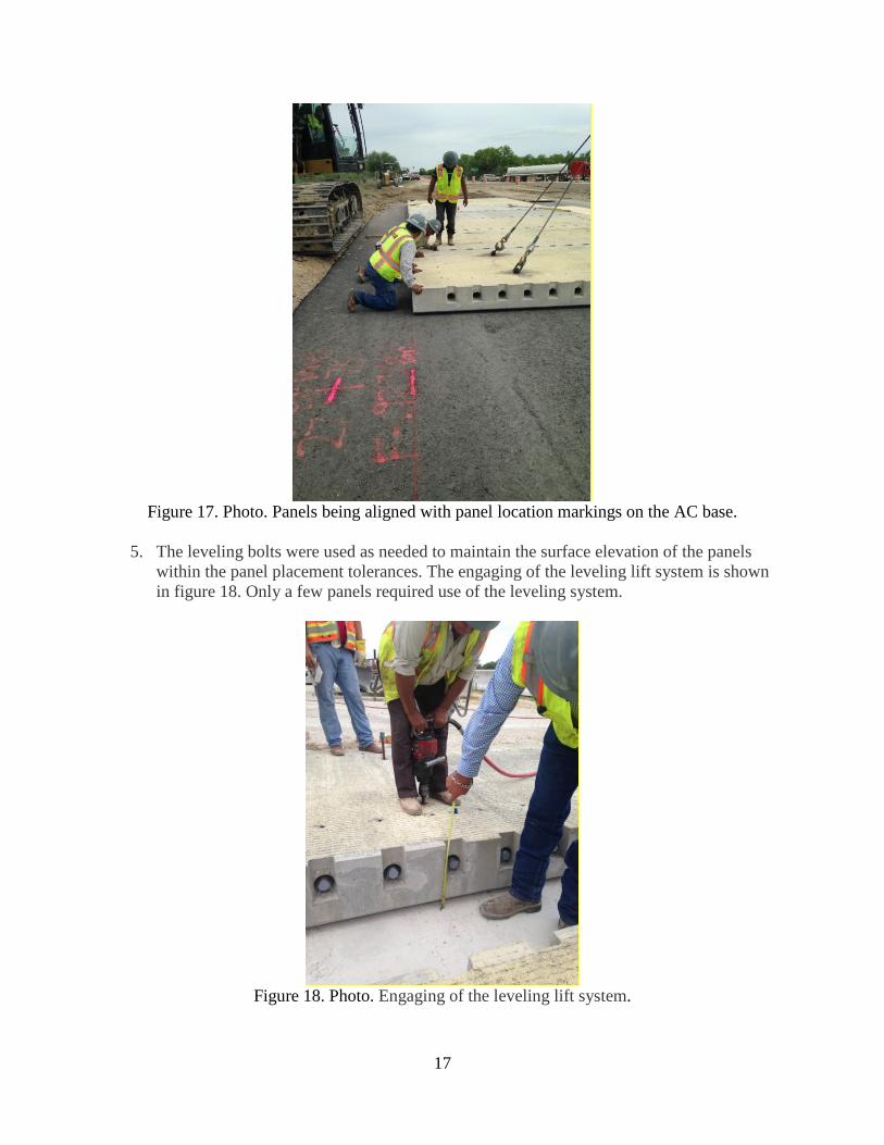
point of placement using a backhoe, as shown in figure 15. Figure 16 shows panel placement over the AC base. Dowel bars with chairs were placed in the ducts along the interior side of the panels. The panels were positioned on the base to line up with panel location markings on the AC base, as shown in figure 17.
16
Figure 15. Photo. Panel being moved from the staging area using a backhoe.
Figure 16. Photo. A panel being placed on the AC base.
17
Figure 17. Photo. Panels being aligned with panel location markings on the AC base.
5. The leveling bolts were used as needed to maintain the surface elevation of the panels
within the panel placement tolerances. The engaging of the leveling lift system is shown in figure 18. Only a few panels required use of the leveling system.
Figure 18. Photo. Engaging of the leveling lift system.
18
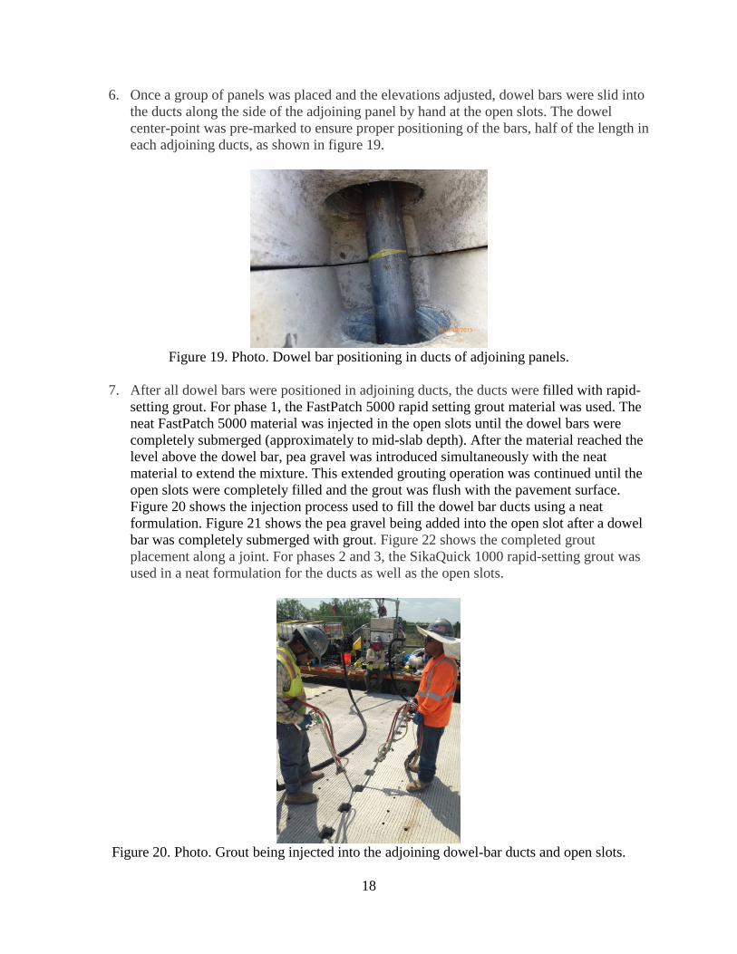
6. Once a group of panels was placed and the elevations adjusted, dowel bars were slid intothe ducts along the side of the adjoining panel by hand at the open slots. The dowelcenter-point was pre-marked to ensure proper positioning of the bars, half of the length ineach adjoining ducts, as shown in figure 19.
Figure 19. Photo. Dowel bar positioning in ducts of adjoining panels.
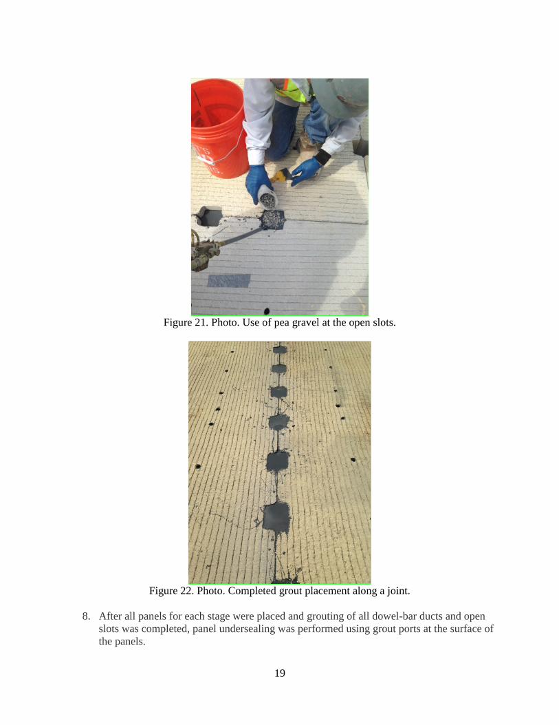
7. After all dowel bars were positioned in adjoining ducts, the ducts were filled with rapid-setting grout. For phase 1, the FastPatch 5000 rapid setting grout material was used. The neat FastPatch 5000 material was injected in the open slots until the dowel bars were completely submerged (approximately to mid-slab depth). After the material reached the level above the dowel bar, pea gravel was introduced simultaneously with the neat material to extend the mixture. This extended grouting operation was continued until the open slots were completely filled and the grout was flush with the pavement surface. Figure 20 shows the injection process used to fill the dowel bar ducts using a neat formulation. Figure 21 shows the pea gravel being added into the open slot after a dowel bar was completely submerged with grout. Figure 22 shows the completed grout placement along a joint. For phases 2 and 3, the SikaQuick 1000 rapid-setting grout was used in a neat formulation for the ducts as well as the open slots.
Figure 20. Photo. Grout being injected into the adjoining dowel-bar ducts and open slots.
19
Figure 21. Photo. Use of pea gravel at the open slots.
Figure 22. Photo. Completed grout placement along a joint.
8. After all panels for each stage were placed and grouting of all dowel-bar ducts and openslots was completed, panel undersealing was performed using grout ports at the surface ofthe panels.

20
9. The cast-in-place reinforced transition slabs were constructed for each stage using ready-mixed concrete. A new hot-mix AC surface was placed over the tapered transition slabsand the adjacent existing AC pavement, which was milled to accommodate the new ACsurface. Figure 23 shows the formwork for the transition slabs, and figure 24 shows thecompleted transition areas.
Figure 23. Photos. Formwork for the cast-in-place transition slabs.
Figure 24. Photos. Views of completed transition areas.
10. The necessary finishing activities were then completed for each stage, includinginstallation of anchors at each outside perimeter panel and joint sawing and sealing. Aview of a sawed and sealed joint is shown in figure 25.
21
Figure 25. Photo. A sawed and sealed joint (December 8, 2016).
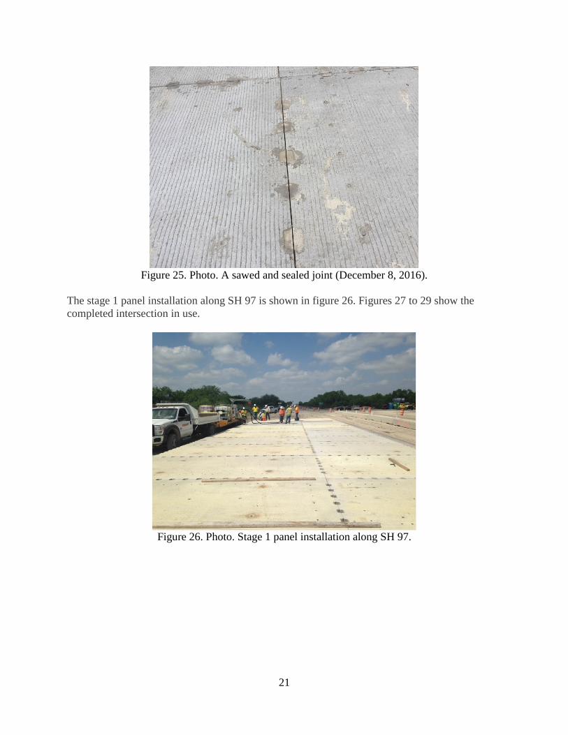
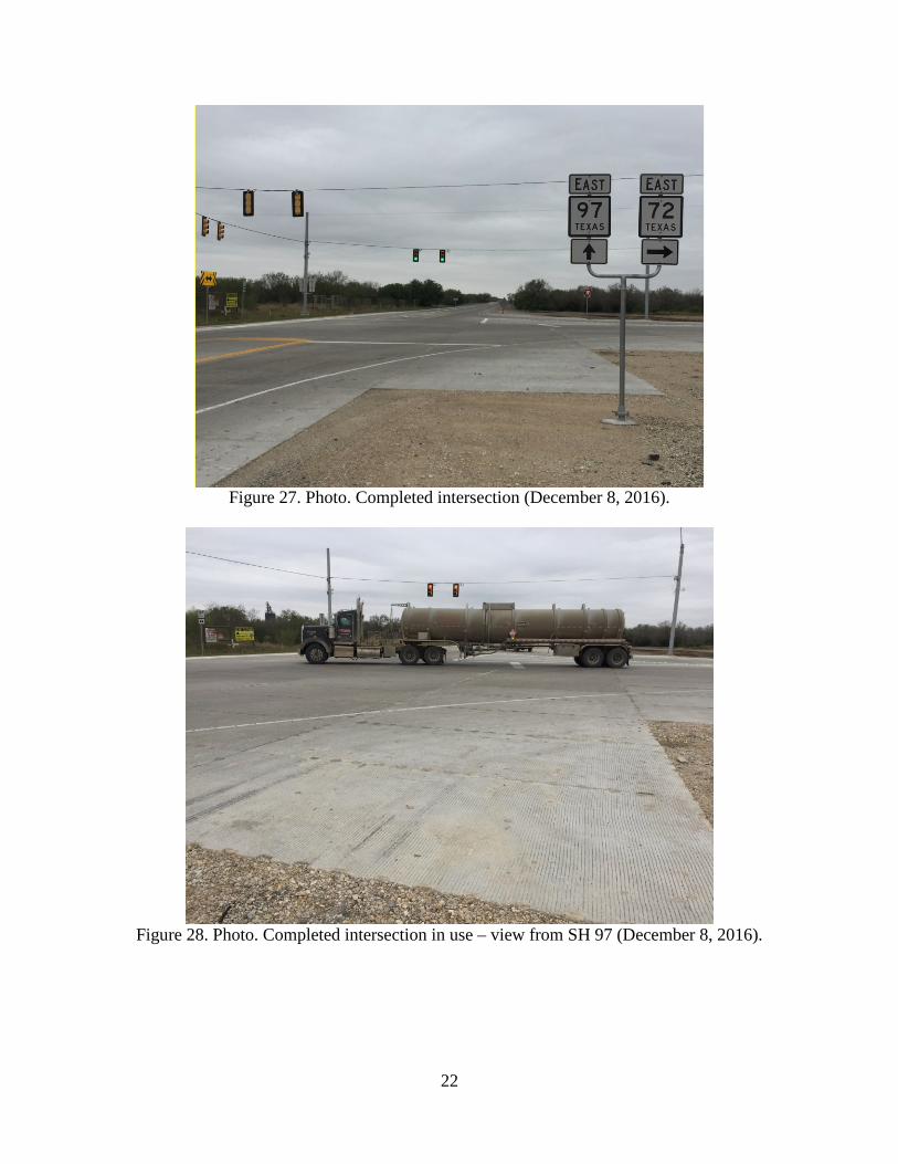
The stage 1 panel installation along SH 97 is shown in figure 26. Figures 27 to 29 show the completed intersection in use.
Figure 26. Photo. Stage 1 panel installation along SH 97.
22
Figure 27. Photo. Completed intersection (December 8, 2016).
Figure 28. Photo. Completed intersection in use – view from SH 97 (December 8, 2016).

23
Figure 29. Photo. Completed intersection in use – view from SH 72 (December 8, 2016).
Since completion of this PCP project, TxDOT has performed deflection testing using the falling weight deflectometer (FWD) and the Total Pavement Acceptance Device (TPAD). The FWD data indicate good deflection response and good load transfer efficiency at the doweled joints, typically in excess of 90 percent. The TPAD data were not available at the time of this report.
A few PCP panels were damaged during handling at the project site, resulting in corner spalls, and a few panels were not aligned with adjoining panels within the specified tolerances. However, the misalignment is not considered significant. Also, the placement of panels was challenging due to the overhead traffic signals and cables.

24

25
SUMMARY AND LESSONS LEARNED
The use of the PCP technology on an actual pavement rehabilitation project was an important step for TxDOT. Although the panel installation did not meet the original requirement to place the panels over a weekend to demonstrate the rapid rehabilitation aspects of PCP use, TxDOT considers the demonstration project at the SH 97 and SH 72 intersection to be successful.
Based on a discussion with TxDOT design and construction staff, the following lessons were learned during the planning, design, and construction phases of this project:
• Allow consideration of alternate PCP systems if the robustness of the PCP system can beverified by TxDOT.
• Allow contractors and precasters to propose innovative PCP systems that result in rapidpanel fabrication and installation, as well as competitive pricing.
• Conduct preconstruction meetings with the contractor to discuss the detailed work plan,including the panel installation schedule.
• Specifications for underslab grouting need to be revised to ensure proper grout equipmentand grout mix design are used.
• Conduct a trial panel installation to ensure that the contractor is capable of performing allaspects of the panel installation work in a timely manner.
• Check the final base surface for smoothness to ensure that panels can be placed at thedesired elevation. The leveling lifts should be included for use as a backup only whenneeded to set the panels at the desired elevation.
• Maintain the daily panel installation rate at a high level to minimize extended laneclosures.
The findings from this demonstration project will help TxDOT to improve plans and specifications as the DOT moves forward to production implementation of the PCP technology for rapid rehabilitation of their network of pavements subjected to high volumes of traffic and where extended traffic control is not acceptable.

26

27
ACKNOWLEDGMENTS
The support of the TxDOT staff during the data collection for this report is gratefully acknowledged. The authors particularly thank Andy Naranjo, P.E, Ruben Carrasco, P.E., and Hua Chen, P.E. Mr. Naranjo provided the construction photographs used in this report.