fhwa project r05 iap funded project case study: new …€¦ · · 2016-12-08fhwa project r05 iap...
TRANSCRIPT
FHWA REPORT NO. FHWA-HIF-17-015
FHWA PROJECT R05 IAP FUNDED PROJECT CASE STUDY
NEW BRITAIN BUS PADS PRECAST CONCRETE
PAVEMENT DEMONSTRATION PROJECT
December 2016
Notice
This document is disseminated under the sponsorship of the U.S. Department of Transportation
in the interest of information exchange. The U.S. Government assumes no liability for the use of
the information contained in this document.
The U.S. Government does not endorse products or manufacturers. Trademarks or
manufacturers' names appear in this report only because they are considered essential to the
objective of the document.
Quality Assurance Statement
The Federal Highway Administration (FHWA) provides high-quality information to serve
Government, industry, and the public in a manner that promotes public understanding. Standards
and policies are used to ensure and maximize the quality, objectivity, utility, and integrity of its
information. FHWA periodically reviews quality issues and adjusts its programs and processes to
ensure continuous quality improvement.
1. Report No.
FHWA-HIF-17-015
2. Government Accession No
3. Recipient’s Catalog No
3. Title and Subtitle
FHWA Project R05 IAP Funded Project Case Study: New Britain Bus
Pads Precast Concrete Pavement Demonstration Project
5. Report Date
December 2016
6. Performing Organization Code
7. Authors
Shiraz Tayabji, Ph.D., P.E.
8. Performing Organization Report No.
9. Performing Organization Name and Address
Applied Research Associates, Inc.
100 Trade Centre Drive, Suite 200
Champaign, IL 61820
10. Work Unit No. (TRAIS) C6B
11. Contract or Grant No.
DTFH61-13-C-00028
12. Sponsoring Agency Name and Address
Office of Infrastructure
Federal Highway Administration
1200 New Jersey Avenue, SE
Washington, DC 20590
13. Type of Report and Period Covered
Final Report
March 2016 – December 2016
14. Sponsoring Agency Code
Project No. 1983
15. Supplementary Notes
Contracting Officer’s Representative: Sam Tyson, P.E.
16. Abstract
The production use of precast concrete pavement (PCP) has come a long way over the last 15 years. The technology is
gaining wider acceptance in the U.S. for rapid repair and rehabilitation of concrete pavements as well as for heavily
trafficked asphalt concrete pavements and intersections. Several U.S. highway agencies have implemented the PCP
technology, and other agencies have constructed demonstration projects.
In the U.S., the PCP technology is being used for intermittent repairs (full-depth joint repairs or full panel
replacement) and for continuous applications (longer length/wider area rehabilitation) with service life expectations of
at least 20 years for intermittent repairs and at least 40 years for continuous applications, without significant future
corrective treatment.
Strategic Highway Research Program 2 (SHRP2) Project R05 was conducted from 2008 to 2012 to develop technical
information and guidelines that would encourage the rapid and successful adoption of PCP technology. In 2013, the
SHRP2 Implementation Assistance Program (IAP) was created to help State highway agencies, metropolitan planning
organizations, and other interested organizations deploy SHRP2-developed products to deliver more efficient, cost-
effective solutions to meet the complex challenges facing transportation agencies. On August 7, 2015, the Federal
Highway Administration—in partnership with the American Association of State Highway and Transportation
Officials—announced the selection of 21 transportation agencies receiving implementation and technical assistance
awards as part of Round 6 of the SHRP2 IAP. The Connecticut Department of Transportation, one of the agencies
selected as a lead adopter of Project R05 technology, received an award of $150,000 to help offset the cost of
constructing a PCP project. Connecticut also received user-incentive funds, in the amount of $75,000, for the
development of plans, specifications, and estimates (PS&E) related technology transfer activities leading to agency-
wide adoption of PCP technology.
This case study report provides details of the 2016 PCP use for rehabilitation of two distressed asphalt concrete bus
pads along a section of the busway of CTfastrak, a bus rapid transit system in New Britain, Connecticut.
17. Key Words
Bus pad rehabilitation, precast concrete pavement
system, construction, pavement rehabilitation,
SHRP2, SHRP2 Project R05
18. Distribution Statement
No restriction.
Security Classification (of this
report): Unclassified
19. Security Classification (of this
page): Unclassified
20. No. of Pages
33
21. Price
Form DOT F 1700.7 (8-72) Reproduction of completed page authorized
ii
TABLE OF CONTENTS
INTRODUCTION ........................................................................................................................ 1
SHRP2 PROJECT R05 BACKGROUND .......................................................................................................... 1
SHRP2 PROJECT R05 PRODUCT IMPLEMENTATION PROGRAM ...................................................... 2
PROJECT DETAILS ................................................................................................................... 3
PROJECT DESCRIPTION ................................................................................................................................. 3
PAVEMENT DETAILS ....................................................................................................................................... 5
PRECAST CONCRETE PAVEMENT SYSTEM DETAILS .......................................................................... 7
CONSTRUCTION STAGING AND TRAFFIC-RELATED REQUIREMENTS ........................................ 10
PANEL FABRICATION ................................................................................................................................... 11
PANEL INSTALLATION ................................................................................................................................. 12
SUMMARY AND LESSONS LEARNED ................................................................................ 25
ACKNOWLEDGMENTS .......................................................................................................... 27
iii
LIST OF FIGURES
Figure 1. Photo. Bus pad locations in New Britain......................................................................... 3 Figure 2. Photo. The AC patch at the north bus pad. ...................................................................... 4 Figure 3. Diagram. Panel layout at the two bus pads...................................................................... 6 Figure 4. Diagram. Panel layout at the north bus pad. .................................................................... 6 Figure 5. Diagram. Panel layout at the south bus pad. ................................................................... 6 Figure 6. Diagram. A typical cross-section at the north bus pad. ................................................... 7 Figure 7. Photo. Dowel bar slots and foam gaskets at the panel bottom. ....................................... 8 Figure 8. Photo. Gracie leveling lift system. .................................................................................. 9 Figure 9. Photo. Transition panel formwork setup. ...................................................................... 13 Figure 10. Photo. Close-up of panel formwork setup. .................................................................. 13
Figure 11. Photo. View of the transitions panel at the staging area.............................................. 14 Figure 12. Photo. Open-graded bedding layer placement at the north bus pad. ........................... 15 Figure 13. Photo. Open-graded bedding layer compaction at the north bus pad. ......................... 15 Figure 14. Photo. Depth of the loosely compacted open-graded bedding layer. .......................... 16 Figure 15. Photo. Removal of about 6 feet of the bedding layer at the north bus pad end. .......... 16 Figure 16. Photo. Removal of the entire bedding layer at the south bus pad. .............................. 17 Figure 17. Photo. Placement of the first panel at the north bus pad. ............................................ 17 Figure 18. Photo. Misaligned transverse sawcut at the first panel location. ................................. 18 Figure 19. Photo. Separating the leveling lift plate from panel bottom. ....................................... 18 Figure 20. Photo. Using leveling bolts to set panel elevation. ...................................................... 19 Figure 21. Photo. Trimming the transition panel at the north bus pad. ........................................ 19 Figure 22. Photo. Transition panel installation at the north bus pad. ........................................... 20 Figure 23. Photo. Panels with leveling lifts engaged at the north bus pad. .................................. 20
Figure 24. Photo. End panel to AC pavement transition area ready for AC surfacing. ................ 21 Figure 25. Photo. Completed AC surfacing at the end of the bus pad. ......................................... 22 Figure 26. Photo. North bus pad in operation (November 29, 2016). .......................................... 22 Figure 27. Photo. South bus pad in operation (November 29, 2016). .......................................... 23
LIST OF TABLES
Table 1. Sublayer aggregate gradation. ........................................................................................... 5 Table 2. Panel geometry tolerances. ............................................................................................. 12

iv
MODERN METRIC CONVERSION FACTORS
Conversion factors both to and from the modern metric International System of Units (SI) can be
found at: http://www.fhwa.dot.gov/publications/convtabl.cfm.
v
ABBREVIATIONS AND ACRONYMS
AASHTO American Association of State Highway and Transportation Officials
AC Asphalt concrete
DOT Department of transportation
FHWA Federal Highway Administration
FMC Fort Miller Company, Inc.
IAP Implementation Assistance Program
PCP Precast concrete pavement
PS&E Plans, specifications, and estimates
SHRP2 Strategic Highway Research Program 2

vi
1
INTRODUCTION
The production use of precast concrete pavement (PCP) has come a long way over the last 15
years. The technology is gaining wider acceptance in the U.S. for rapid repair and rehabilitation
of concrete pavements as well as for heavily trafficked asphalt concrete pavements and
intersections. Several U.S. highway agencies—including Caltrans, Illinois Tollway, and the New
Jersey, New York, and Utah State Departments of Transportation (DOTs)—have implemented
the PCP technology, and other agencies have constructed demonstration projects. There have
also been many advances in the design, panel fabrication, and panel installation aspects of the
PCP technology.
In the U.S., the PCP technology is being used for intermittent repairs (full-depth joint repairs or
full panel replacement) and for continuous applications (longer length/wider area rehabilitation)
with service life expectations of at least 20 years for intermittent repairs and at least 40 years for
continuous applications, without significant future corrective treatment.
PCP technology can significantly reduce traffic impacts of roadway repair and reconstruction
projects, particularly on heavily traveled routes. The technology is applicable to small segments,
enabling flexibility in construction phasing, as well as for use in corridor-wide pavement
reconstruction.
SHRP2 PROJECT R05 BACKGROUND
Because the information on PCP technology was not well documented, in 2007 the Strategic
Highway Research Program 2 (SHRP2) initiated Project R05 to develop the necessary technical
information and guidelines that would encourage the rapid and successful adoption of this new
technology. The Project R05 study was conducted from 2008 to 2012. The final report, Precast
Concrete Pavement Technology, is available at http://www.trb.org/main/blurbs/167788.aspx.
The study demonstrated that the PCP technology is ready for wider implementation and that
many of the PCP systems available in the U.S. can meet the needs of highway agencies for rapid
renewal of their highway systems. The following products were developed under SHRP2 Project
R05:
Overall findings related to viability of the PCP technology.
Findings based on SHRP2 field testing.
Guidelines for PCP project selection.
Guidelines for PCP system acceptance.
Guidelines for design of PCP systems.
Guidelines for PCP fabrication.
Guidelines for PCP installation.
Implementation plan for PCP technology.
Long-term monitoring plan for PCP projects.
Model specifications.
2
The review of projects constructed in the U.S. and the SHRP2 field testing indicated that
sufficient advances have been made to reliably design and construct PCP systems to achieve five
key attributes of successful pavements, as follows:
Constructability—Techniques and equipment are available to ensure acceptable
production rates for the installation of PCP systems.
Concrete durability—Plant fabrication of precast panels results in excellent concrete
strength and durability.
Load transfer at joints—Reliable and economical techniques are available to provide
effective load transfer at transverse joints in jointed PCP systems and post-tensioned PCP
systems.
Panel support—Techniques to provide adequate and uniform base support conditions
continue to be improved.
Efficiency—Panels are thinner than standard cast-in-place concrete and last longer
because of prestressing and/or reinforcing elements in the PCP system.
SHRP2 PROJECT R05 PRODUCT IMPLEMENTATION PROGRAM
In 2013, the Federal Highway Administration (FHWA) and the American Association of State
Highway and Transportation Officials (AASHTO) created the SHRP2 Implementation
Assistance Program (IAP) to help State DOTs, metropolitan planning organizations, and other
interested organizations deploy SHRP2-developed products to deliver more efficient, cost-
effective solutions to meet complex challenges. Seven rounds of the IAP were offered between
February 2013 and April 2016.
On August 7, 2015, FHWA—in partnership with AASHTO—announced the selection of 21
transportation agencies receiving implementation and technical assistance awards as part of
Round 6 of the SHRP2 IAP. The Connecticut DOT, one of the agencies selected as a lead
adopter of Project R05 technology, received an award of $150,000 to help offset the cost of
constructing a PCP project that would provide a learning environment for operations such as
fabricating panels, setting panels, installing dowel bars, grouting under panel areas, and other
related activities needed to implement precast panel installations in Connecticut. The DOT also
received user-incentive funds, in the amount of $75,000, for the development of plans,
specifications, and estimates (PS&E) related technology transfer activities leading to agency-
wide adoption of PCP technology.
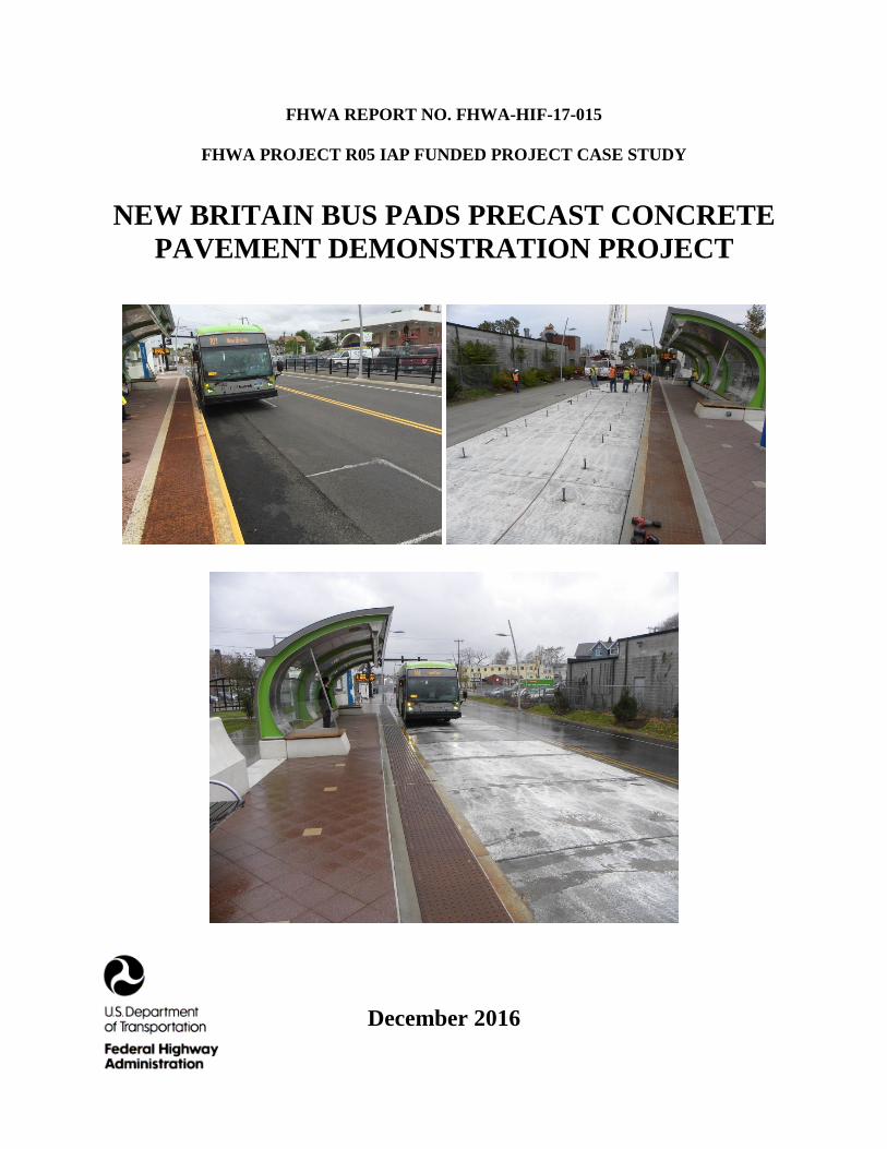
This case study report provides details of the PCP implementation to rehabilitate two distressed
asphalt concrete (AC) bus pads along a section of the busway of CTfastrak, a bus rapid transit
system in New Britain, Connecticut. The bus pads at East Main Street Station were rehabilitated
over a weekend in October 2016.
3
PROJECT DETAILS
PROJECT DESCRIPTION
CTfastrak is a regional bus rapid transit system currently operating between Union Station in
Hartford and Downtown New Britain station in New Britain in central Connecticut. Owned and
operated by Connecticut Transit (CTtransit), CTfastrak opened on March 28, 2015. CTfastrak
services run on a 9.4-mile dedicated busway which runs on an abandoned railroad right-of-way
from Downtown New Britain to Newington Junction and alongside the active New Haven-
Springfield Line from Newington Junction to downtown Hartford. Five local and four express
routes operate along the busway. As of October 2016, the average weekday CTfastrak passenger
count was about 12,000.
The CTfastrak busway is two lanes, one in each direction. Seven stations along the busway have
basic side platforms and, except the East Main Street Station, they have center passing lanes to
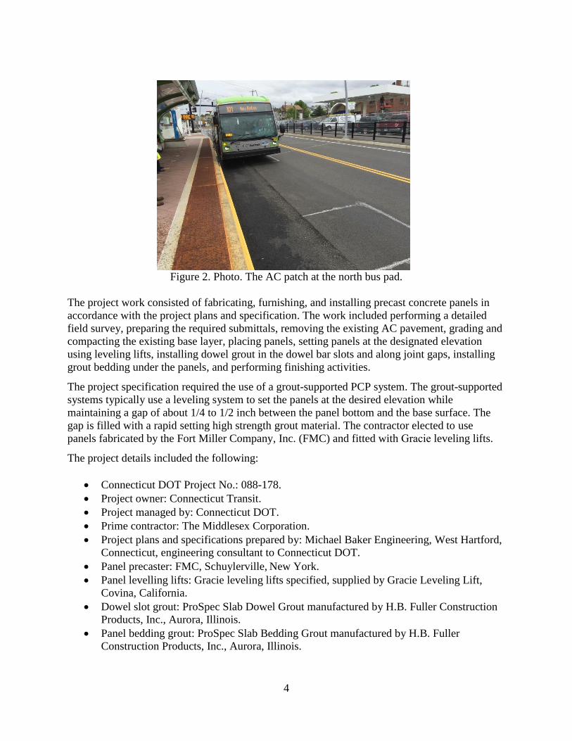
allow express buses to pass stopped local buses. About 110 feet of the AC pavement at each of
the two bus pads at the East Main Street Station had been exhibiting rutting since the busway
became operational in early 2015. The rutting was along the outside bus wheel path close to the
platforms and was serious enough to prevent opening of the bus doors at the platforms. To
correct the excessive rutting, the bus pads had been patched several times. Based on discussions
between CTtransit and Connecticut DOT, it was decided to seek a permanent solution to the bus
pad rutting problem at the East Main Street Station. The DOT recommended using PCP to allow
the rehabilitation work to be performed over a weekend without disturbing the heavy weekday
bus commuter traffic. Connecticut DOT managed the rehabilitation work for CTtransit.
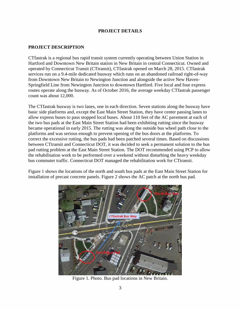
Figure 1 shows the locations of the north and south bus pads at the East Main Street Station for
installation of precast concrete panels. Figure 2 shows the AC patch at the north bus pad.
Figure 1. Photo. Bus pad locations in New Britain.
4
Figure 2. Photo. The AC patch at the north bus pad.
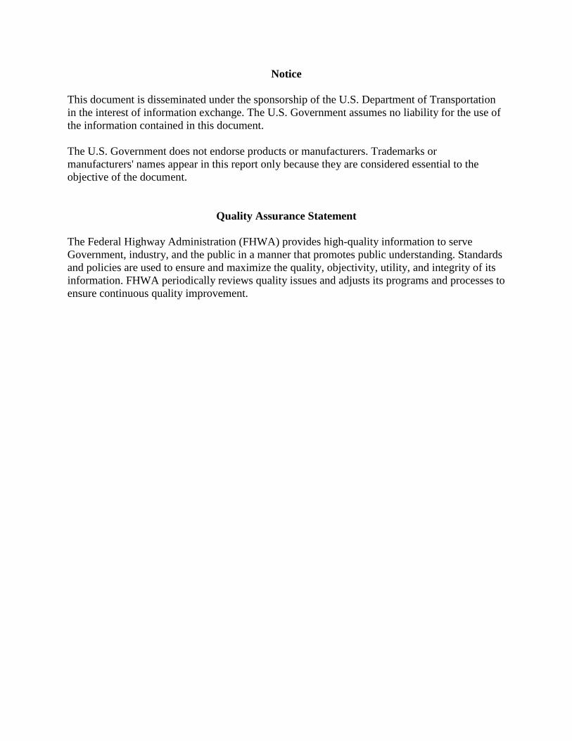
The project work consisted of fabricating, furnishing, and installing precast concrete panels in
accordance with the project plans and specification. The work included performing a detailed
field survey, preparing the required submittals, removing the existing AC pavement, grading and
compacting the existing base layer, placing panels, setting panels at the designated elevation
using leveling lifts, installing dowel grout in the dowel bar slots and along joint gaps, installing
grout bedding under the panels, and performing finishing activities.
The project specification required the use of a grout-supported PCP system. The grout-supported
systems typically use a leveling system to set the panels at the desired elevation while
maintaining a gap of about 1/4 to 1/2 inch between the panel bottom and the base surface. The
gap is filled with a rapid setting high strength grout material. The contractor elected to use
panels fabricated by the Fort Miller Company, Inc. (FMC) and fitted with Gracie leveling lifts.
The project details included the following:
Connecticut DOT Project No.: 088-178.
Project owner: Connecticut Transit.
Project managed by: Connecticut DOT.
Prime contractor: The Middlesex Corporation.
Project plans and specifications prepared by: Michael Baker Engineering, West Hartford,
Connecticut, engineering consultant to Connecticut DOT.
Panel precaster: FMC, Schuylerville, New York.
Panel levelling lifts: Gracie leveling lifts specified, supplied by Gracie Leveling Lift,
Covina, California.
Dowel slot grout: ProSpec Slab Dowel Grout manufactured by H.B. Fuller Construction
Products, Inc., Aurora, Illinois.
Panel bedding grout: ProSpec Slab Bedding Grout manufactured by H.B. Fuller
Construction Products, Inc., Aurora, Illinois.
5
PAVEMENT DETAILS
The original pavement (two busway lanes) is a 10.5-inch-thick AC pavement that was
constructed in 2015 and opened to bus traffic in April 2015. The details of the bus pads
rehabilitation are as follows:
Existing AC pavement.
o AC thickness: 10.5 inches.
o Processed aggregate base: 6 inches.
o Granular subbase: 10 inches.
Length of panel installation at each bus pad: 106 feet.
Total number of panels installed: 12 at each bus pad.
o Panel thickness: 10 inches.
o Panel width: 15 feet.
o Length of standard panel: 9 feet.
o Length of transition panels at each end: 8 feet.
o The approach and leave transition panels at each bus pad had a taper to facilitate
the transition from and to the existing AC pavement.
o Panels to be set using Gracie leveling lifts.
Base for the PCP: Regraded and compacted existing granular base, supplemented, as
necessary, by new processed base material passing the 3/4-inch sieve. New processed
material to conform to the requirements under Article M.05.01 with the exception that the
gradation of the material to be modified as shown in table 1.
Bedding layer over the base: Rapid-setting grout.
Joint load transfer: 14-inch-long dowel bars uniformly spaced at 12 inches; dowel
diameter of 1.25 inches.
Dowel bar slot grout: Capable of being pumped into the slots; a minimum compressive
strength of 2,500 psi before the panels are open to traffic and a minimum compressive
strength of 4,000 psi at 28 days.
Panel bedding grout: Capable of being pumped into the slots; a minimum compressive
strength of 500 psi before the panels are open to traffic and a minimum compressive
strength of 4,000 psi at 28 days.
Finishing activity: Mill approaches and departures area AC pavement and place new AC
surface to match the PCP grade.
Table 1. Sublayer aggregate gradation.
Square Mesh Sieves Percent Passing by Mass
Passing 3/4 inch (19 mm) 100
Passing 1/4 inch (6.3 mm) 25-45
Passing #40 (425 µm) 5-20
Passing #100 (150 µm) 2-12
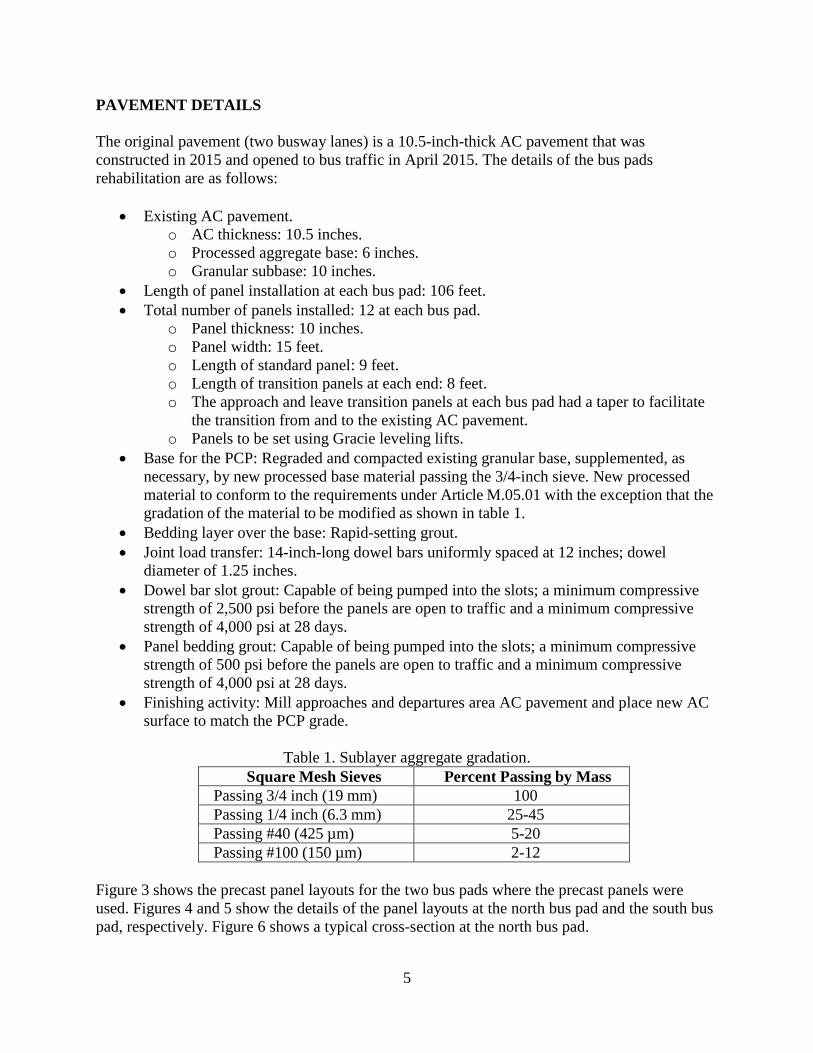
Figure 3 shows the precast panel layouts for the two bus pads where the precast panels were
used. Figures 4 and 5 show the details of the panel layouts at the north bus pad and the south bus
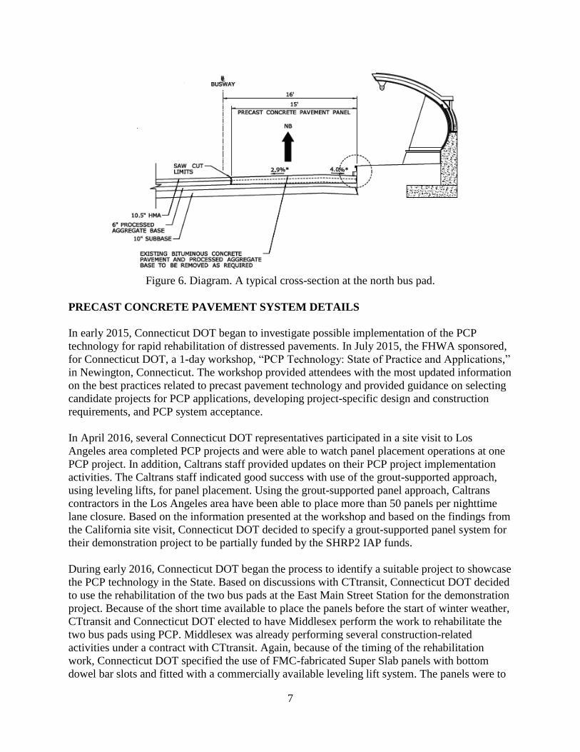
pad, respectively. Figure 6 shows a typical cross-section at the north bus pad.
6
Figure 3. Diagram. Panel layout at the two bus pads.
Figure 4. Diagram. Panel layout at the north bus pad.
Figure 5. Diagram. Panel layout at the south bus pad.
7
Figure 6. Diagram. A typical cross-section at the north bus pad.
PRECAST CONCRETE PAVEMENT SYSTEM DETAILS
In early 2015, Connecticut DOT began to investigate possible implementation of the PCP
technology for rapid rehabilitation of distressed pavements. In July 2015, the FHWA sponsored,
for Connecticut DOT, a 1-day workshop, “PCP Technology: State of Practice and Applications,”
in Newington, Connecticut. The workshop provided attendees with the most updated information
on the best practices related to precast pavement technology and provided guidance on selecting
candidate projects for PCP applications, developing project-specific design and construction
requirements, and PCP system acceptance. In April 2016, several Connecticut DOT representatives participated in a site visit to Los
Angeles area completed PCP projects and were able to watch panel placement operations at one
PCP project. In addition, Caltrans staff provided updates on their PCP project implementation
activities. The Caltrans staff indicated good success with use of the grout-supported approach,
using leveling lifts, for panel placement. Using the grout-supported panel approach, Caltrans
contractors in the Los Angeles area have been able to place more than 50 panels per nighttime
lane closure. Based on the information presented at the workshop and based on the findings from
the California site visit, Connecticut DOT decided to specify a grout-supported panel system for
their demonstration project to be partially funded by the SHRP2 IAP funds.
During early 2016, Connecticut DOT began the process to identify a suitable project to showcase
the PCP technology in the State. Based on discussions with CTtransit, Connecticut DOT decided
to use the rehabilitation of the two bus pads at the East Main Street Station for the demonstration
project. Because of the short time available to place the panels before the start of winter weather,
CTtransit and Connecticut DOT elected to have Middlesex perform the work to rehabilitate the
two bus pads using PCP. Middlesex was already performing several construction-related
activities under a contract with CTtransit. Again, because of the timing of the rehabilitation
work, Connecticut DOT specified the use of FMC-fabricated Super Slab panels with bottom
dowel bar slots and fitted with a commercially available leveling lift system. The panels were to
8
be fabricated at the FMC precast plant in Schuylerville, New York, about 170 miles from the
project site and delivered to a staging area near the project site a few days before panel
placement. The Super Slab panels used for this project are part of a proprietary system developed
by FMC in 2001. Since 2001, several highway agencies have used the Super Slab panels for
intermittent concrete pavement repairs and for rehabilitation of concrete and asphalt pavements.
The PCP system, as designed by Connecticut DOT for this project, consisted of the following
components.
Reinforced Precast Panels Fabricated by FMC
The Super Slab panels, incorporating bottom dowel bar slots, are fabricated in an approved
precast concrete plant, always using steel forms. The Super Slab panels typically incorporate the
following features:
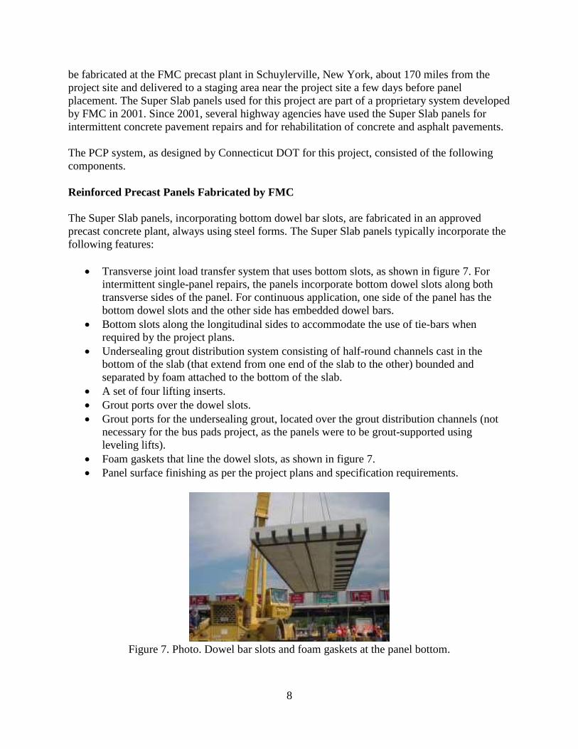
Transverse joint load transfer system that uses bottom slots, as shown in figure 7. For
intermittent single-panel repairs, the panels incorporate bottom dowel slots along both
transverse sides of the panel. For continuous application, one side of the panel has the
bottom dowel slots and the other side has embedded dowel bars.
Bottom slots along the longitudinal sides to accommodate the use of tie-bars when
required by the project plans.
Undersealing grout distribution system consisting of half-round channels cast in the
bottom of the slab (that extend from one end of the slab to the other) bounded and
separated by foam attached to the bottom of the slab.
A set of four lifting inserts.
Grout ports over the dowel slots.
Grout ports for the undersealing grout, located over the grout distribution channels (not
necessary for the bus pads project, as the panels were to be grout-supported using
leveling lifts).
Foam gaskets that line the dowel slots, as shown in figure 7.
Panel surface finishing as per the project plans and specification requirements.
Figure 7. Photo. Dowel bar slots and foam gaskets at the panel bottom.
9
Leveling Lift System
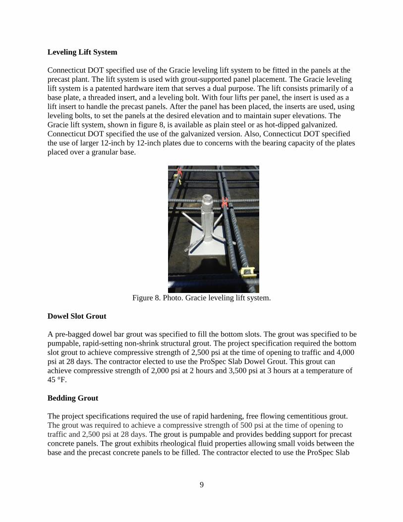
Connecticut DOT specified use of the Gracie leveling lift system to be fitted in the panels at the
precast plant. The lift system is used with grout-supported panel placement. The Gracie leveling
lift system is a patented hardware item that serves a dual purpose. The lift consists primarily of a
base plate, a threaded insert, and a leveling bolt. With four lifts per panel, the insert is used as a
lift insert to handle the precast panels. After the panel has been placed, the inserts are used, using
leveling bolts, to set the panels at the desired elevation and to maintain super elevations. The
Gracie lift system, shown in figure 8, is available as plain steel or as hot-dipped galvanized.
Connecticut DOT specified the use of the galvanized version. Also, Connecticut DOT specified
the use of larger 12-inch by 12-inch plates due to concerns with the bearing capacity of the plates
placed over a granular base.
Figure 8. Photo. Gracie leveling lift system.
Dowel Slot Grout
A pre-bagged dowel bar grout was specified to fill the bottom slots. The grout was specified to be
pumpable, rapid-setting non-shrink structural grout. The project specification required the bottom
slot grout to achieve compressive strength of 2,500 psi at the time of opening to traffic and 4,000
psi at 28 days. The contractor elected to use the ProSpec Slab Dowel Grout. This grout can
achieve compressive strength of 2,000 psi at 2 hours and 3,500 psi at 3 hours at a temperature of
45 °F.
Bedding Grout
The project specifications required the use of rapid hardening, free flowing cementitious grout.
The grout was required to achieve a compressive strength of 500 psi at the time of opening to
traffic and 2,500 psi at 28 days. The grout is pumpable and provides bedding support for precast
concrete panels. The grout exhibits rheological fluid properties allowing small voids between the
base and the precast concrete panels to be filled. The contractor elected to use the ProSpec Slab
10
Bedding Grout - Rapid. This grout can achieve a compressive strength of 1,400 psi at 45 minutes
and 5,500 psi at 28 days when tested in the laboratory at a temperature of 72 °F.
Panel Installation
The following are the installation steps for the PCP system designed by Connecticut DOT:
1. Mark repair limits (engineer) and measure existing lane width (contractor).
2. Remove existing pavement.
3. Prepare existing base and supplement with new crushed stone base as necessary (grade
and compact).
4. Place panels over the prepared base layer, with the bottom slots located over the dowel
bars or in the adjacent panels. The first and last panels in each bus pad area were set
against the existing AC pavement face. These panels also incorporated a 3-foot-long
taper to allow transitioning from the PCP panels to the adjacent AC pavement.
5. Maintain the transverse joint widths as specified.
6. Engage the leveling lifts and raise the panels to the desired elevation. For the bus pad
project, the requirement was to have the panel surface to match the AC pavement surface.
7. Grout the bottom slots and the joint gaps around each panel.
8. Apply the bedding grout.
9. Remove the leveling bolts.
10. Perform finishing activities.
11. Open to traffic.
The project specification required the panels to be installed within the following tolerances:
The vertical differential between adjacent precast panels across any joint to be 1/8 inch or
less.
Transverse joint width between adjacent panels to not exceed 1/2 inch.
Longitudinal joint width at the busway centerline to not exceed 1 inch and along the
curb-line (platform side) to not exceed 2 inches.
The bedding grout to be a minimum of 3/4 inch to accommodate the 3/4-inch-thick
Gracie lift base plates.
CONSTRUCTION STAGING AND TRAFFIC-RELATED REQUIREMENTS
The busway is in operation from 4:00 am to 1:00 am weekdays, leaving only a 3-hour closure
each night. On Saturdays, the busway is in use from about 5:00 am until 1:00 am (4-hour
window), and on Sundays it is in use from 7:00 am until 9:00 pm (10-hour window). Based on
discussions between Connecticut DOT and CTtransit, it was decided to remove the AC
pavement and install the precast panels at the two East Main Street bus pads during a weekend
closure. During the closure, the buses using the busway would be detoured along local streets
for about two blocks along each side of the station. The project specification allowed one 48-
hour work shift between 2:00 am Saturday and 2:00 am Monday during one weekend in
October 2016, excluding Columbus Day weekend.
11
The contractor’s proposed schedule for the work is summarized below:
Thursday, 1:00 am to 4:00 am: Sawcut AC pavement.
Friday: Ship panels from the FMC plant in Schuylerville, New York, to a staging site
adjacent to the busway, about a mile away from East Street Station.
Friday, 10:00 pm to 11:00 pm: Maintenance and protection of traffic.
Friday, 11:00 pm to 1:00 am: Remove rub-rails and anchor bolts along the sides of the
platforms.
Saturday, 1:00 am to 4:00 am: Remove existing AC pavement.
Saturday, 5:00 am to 7:00 am: Grade and compact base.
Saturday, 7:00 am to ll:00 am: Set precast concrete pavement panels.
Saturday, 8:00 am to10:00 am: Drill and grout rub-rail anchor bolts.
Saturday, ll:00 am to 3:00 pm: Set panels at the design elevation using leveling lifts and
install dowel slot grout.
Saturday, 3:00 pm to Sunday, 4:00 am: Install bedding grout.
Sunday, 4:00 am to ll:00 am: Reinstall rub-rails.
Sunday, ll:00 am to 5:00 pm: Mill and pave AC approaches.
The work to remove the distressed AC pavement at the two bus pads was intiated during the
night of Thursday, October 27, 2016, when the AC pavement designated for removal was sawcut
full-depth in 7-foot by 5-foot segments. The AC pavement removal work was begun during the
night of Friday, October 28, 2016, and most of the panel installation activities were completed by
early morning on Monday, October 30, 2016. Bus traffic was allowed to use the completed bus
pads at 4:00 am, the start of Monday morning’s CTfastrak operation.
As discussed later, the contractor was not able to follow the proposed schedule due to a delay in
grading and compacting the base at the north bus pad. The panel installation at the north bus pad
was completed late afternoon on Saturday, and the panel installation at the south bus pad was
completed early Sunday morning. The dowel slot grout and bedding grout application was
completed by Sunday afternoon. However, the joints could only be partially filled with the dowel
slot grout material due to lack of grout material. The joint gaps were filled with the grout during
a short closure the following weekend.
Before the field installation work started, Connecticut DOT conducted extensive public
awareness activities. Police cars were posted at all crtical intersections to ensure local traffic
flow was not impeded along East Main Street.
PANEL FABRICATION
The 24 panels were fabricated in early October 2016 at the FMC precast plant in Schuylerville,
New York. The panels were fabricated based on shop drawings prepared by FMC and approved
by Connecticut DOT. All panels were rectangular in shape and included four transition panels.
Key panel fabrication requirements from the project specification are given below:
Concrete mixture to meet the requirements of Article M.14.01.1 and having a minimum
28-day compressive strength of 5,000 psi.
12
Use of epoxy-coated steel reinforcement.
The leveling system to be Gracie Leveling Lift, and each Gracie Leveling Lift baseplate to
be a steel plate measuring a minimum of 3/4 inch by 12 inches by 12 inches.
Panels to be provided with an accurately screeded top surface. The surface to be tined in
the transverse direction. Tines to be 1/8 inch deep and spaced at 3/4 inch.
Casting panels to meet the tolerances given in table 2.
Application of curing to the panel surface soon after concrete placement and application
of curing to the bottom and all four sides of the panel soon after formwork removal.
Table 2. Panel geometry tolerances.
Material Proportion
Length +/- 3/16 inch
Width +/- 3/16 inch
Thickness +/-1/8 inch
Edge Squareness 1/8 inch in 10 inches in relation to
top and bottom surfaces
Diagonals +/-3/16 inch
Delta (Warp) +/‐ 1/8 inch
As part of the panel fabrication process, the ready-mixed concrete was regularly tested for fresh
properties and for strength. The concrete typically exceeded the design compressive strength of
5,000 psi at 28 days and typically exceeded 3,000 psi at about 16 hours to allow for panel form
stripping. Figure 9 shows a view of the transition panel formwork, and figure 10 is a detailed
view of the panel formwork.
The panels were stored at the facility and were delivered to a staging area near the project site a
day before panel placement.
PANEL INSTALLATION
Panels were installed during the weekend of October 28 to 29. The panels were transported from
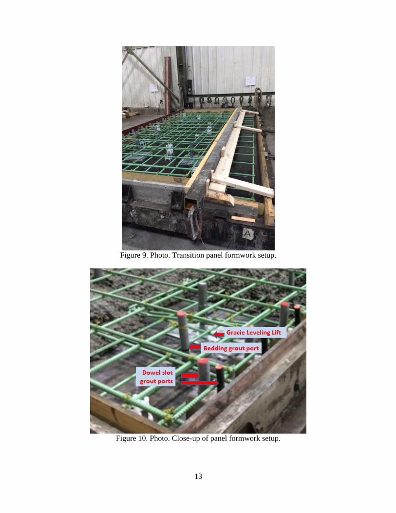
the nearby staging area to the project site as needed. A view of the transition panels at the staging
area is shown in figure 11.
13
Figure 9. Photo. Transition panel formwork setup.
Figure 10. Photo. Close-up of panel formwork setup.
14
Figure 11. Photo. View of the transitions panel at the staging area.
The panel installation order, as planned for by the contractor, was as follows:
1. North bus pad.
a. Finish base grading and compaction, including use of new crushed stone material
to correct for any over-excavation of the existing base.
b. Place the 12 panels at the bus pad.
c. Use 48 leveling bolts to set panels at the desired elevation matching the adjacent
AC pavement.
d. Grout the bottom dowel bar slots and fill all joint gaps to level of the panel
surface.
e. Remove leveling bolts as soon as the dowel bar slot had hardened sufficiently to
carry the weight of the panels. Use the leveling bolts to set the 12 panels at the
south bus pad.
f. Apply the bedding grout under the panels.
g. Apply finishing activities.
i. Mill about 3 inches of the AC surface for a distance of about 10 ft at each
end of the bus pads. Place hot-mix AC surfacing over the milled portion of
the AC pavement and over the transition panels.
ii. Saw and seal joints.
2. South bus pad.
a. Repeat all activities listed above.
Closure of the busway at the two bus pads was initiated on Friday night (October 28). The
existing AC pavement was removed at both bus pads early Saturday morning. The AC pavement
was removed in 5-by-7-foot segments. Work was carried out simultaneously at both bus pads to
finish grading the existing base and to add new base material where the base had been over-
excavated. It had been expected that the over-excavation of the base would be limited to about
1/2 to 1 inch. However, due to a miscommunication between the contractor and the FMC
representative helping the contractor with the panel installation work, the existing base was over-
excavated by up to 4 inches and the existing compacted base was overlaid with an open-graded
15
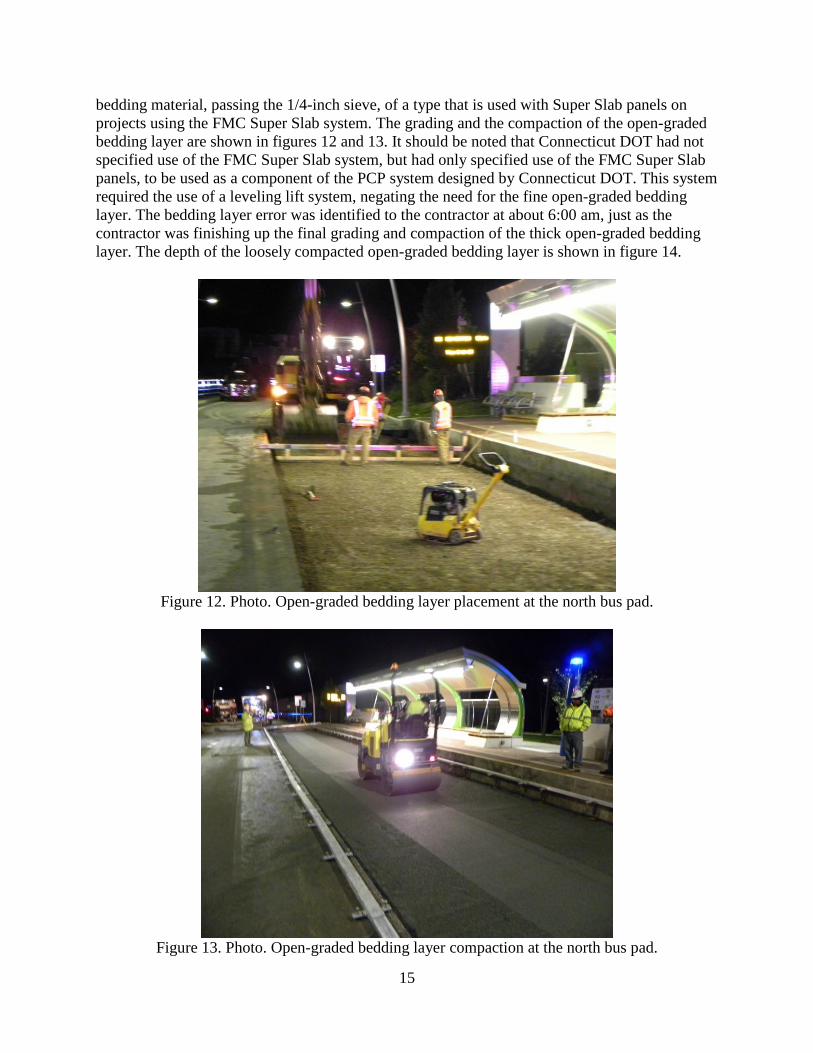
bedding material, passing the 1/4-inch sieve, of a type that is used with Super Slab panels on
projects using the FMC Super Slab system. The grading and the compaction of the open-graded
bedding layer are shown in figures 12 and 13. It should be noted that Connecticut DOT had not
specified use of the FMC Super Slab system, but had only specified use of the FMC Super Slab
panels, to be used as a component of the PCP system designed by Connecticut DOT. This system
required the use of a leveling lift system, negating the need for the fine open-graded bedding
layer. The bedding layer error was identified to the contractor at about 6:00 am, just as the
contractor was finishing up the final grading and compaction of the thick open-graded bedding
layer. The depth of the loosely compacted open-graded bedding layer is shown in figure 14.
Figure 12. Photo. Open-graded bedding layer placement at the north bus pad.
Figure 13. Photo. Open-graded bedding layer compaction at the north bus pad.
16
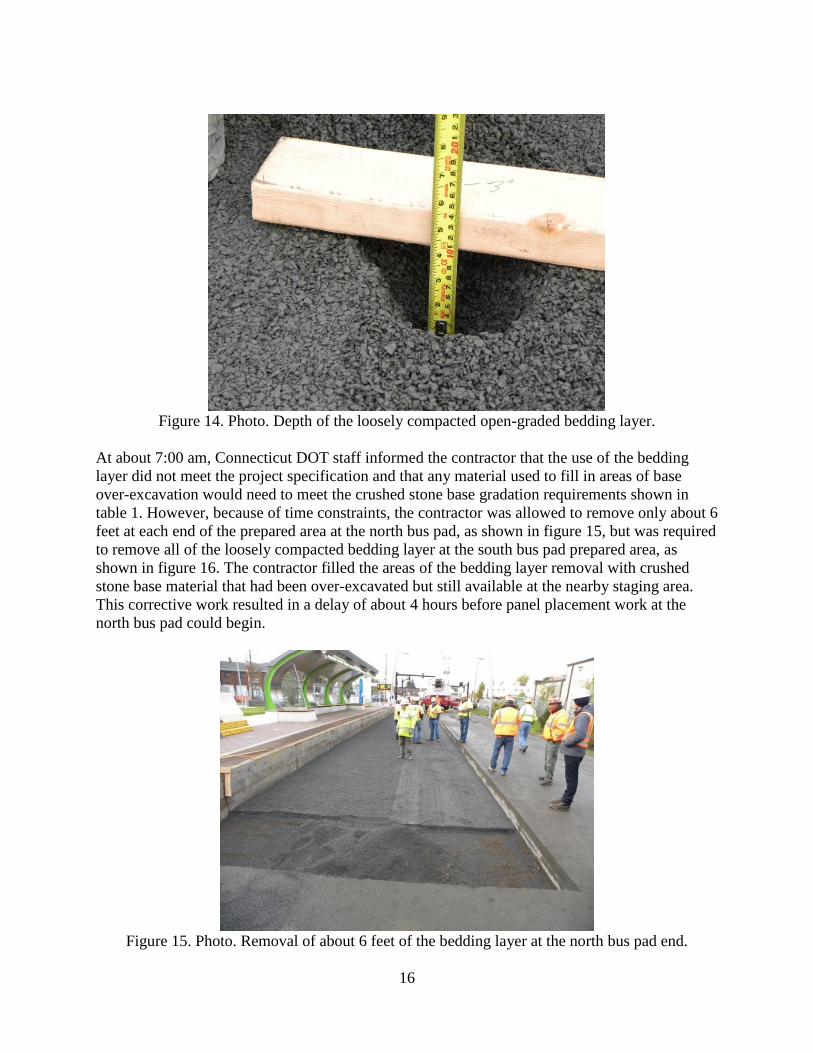
Figure 14. Photo. Depth of the loosely compacted open-graded bedding layer.
At about 7:00 am, Connecticut DOT staff informed the contractor that the use of the bedding
layer did not meet the project specification and that any material used to fill in areas of base
over-excavation would need to meet the crushed stone base gradation requirements shown in
table 1. However, because of time constraints, the contractor was allowed to remove only about 6
feet at each end of the prepared area at the north bus pad, as shown in figure 15, but was required
to remove all of the loosely compacted bedding layer at the south bus pad prepared area, as
shown in figure 16. The contractor filled the areas of the bedding layer removal with crushed
stone base material that had been over-excavated but still available at the nearby staging area.
This corrective work resulted in a delay of about 4 hours before panel placement work at the
north bus pad could begin.
Figure 15. Photo. Removal of about 6 feet of the bedding layer at the north bus pad end.
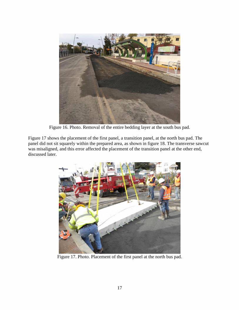
17
Figure 16. Photo. Removal of the entire bedding layer at the south bus pad.
Figure 17 shows the placement of the first panel, a transition panel, at the north bus pad. The
panel did not sit squarely within the prepared area, as shown in figure 18. The transverse sawcut
was misaligned, and this error affected the placement of the transition panel at the other end,
discussed later.
Figure 17. Photo. Placement of the first panel at the north bus pad.
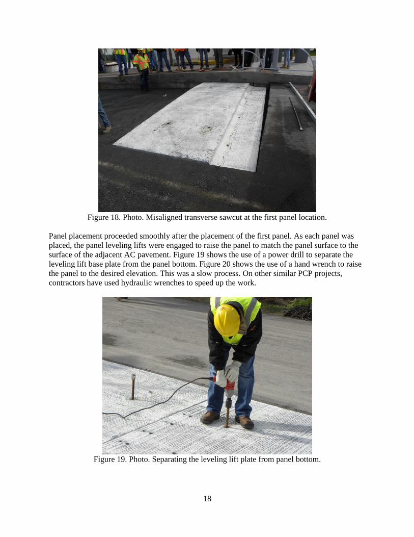
18
Figure 18. Photo. Misaligned transverse sawcut at the first panel location.
Panel placement proceeded smoothly after the placement of the first panel. As each panel was
placed, the panel leveling lifts were engaged to raise the panel to match the panel surface to the
surface of the adjacent AC pavement. Figure 19 shows the use of a power drill to separate the
leveling lift base plate from the panel bottom. Figure 20 shows the use of a hand wrench to raise
the panel to the desired elevation. This was a slow process. On other similar PCP projects,
contractors have used hydraulic wrenches to speed up the work.
Figure 19. Photo. Separating the leveling lift plate from panel bottom.
19
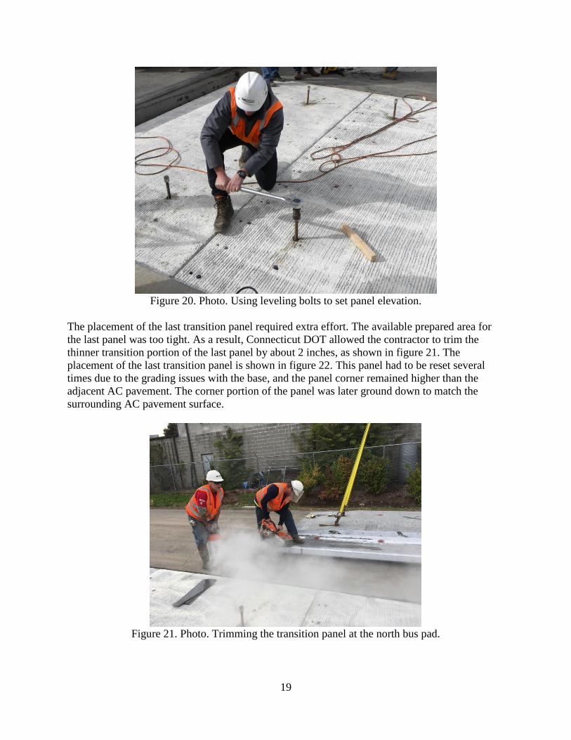
Figure 20. Photo. Using leveling bolts to set panel elevation.
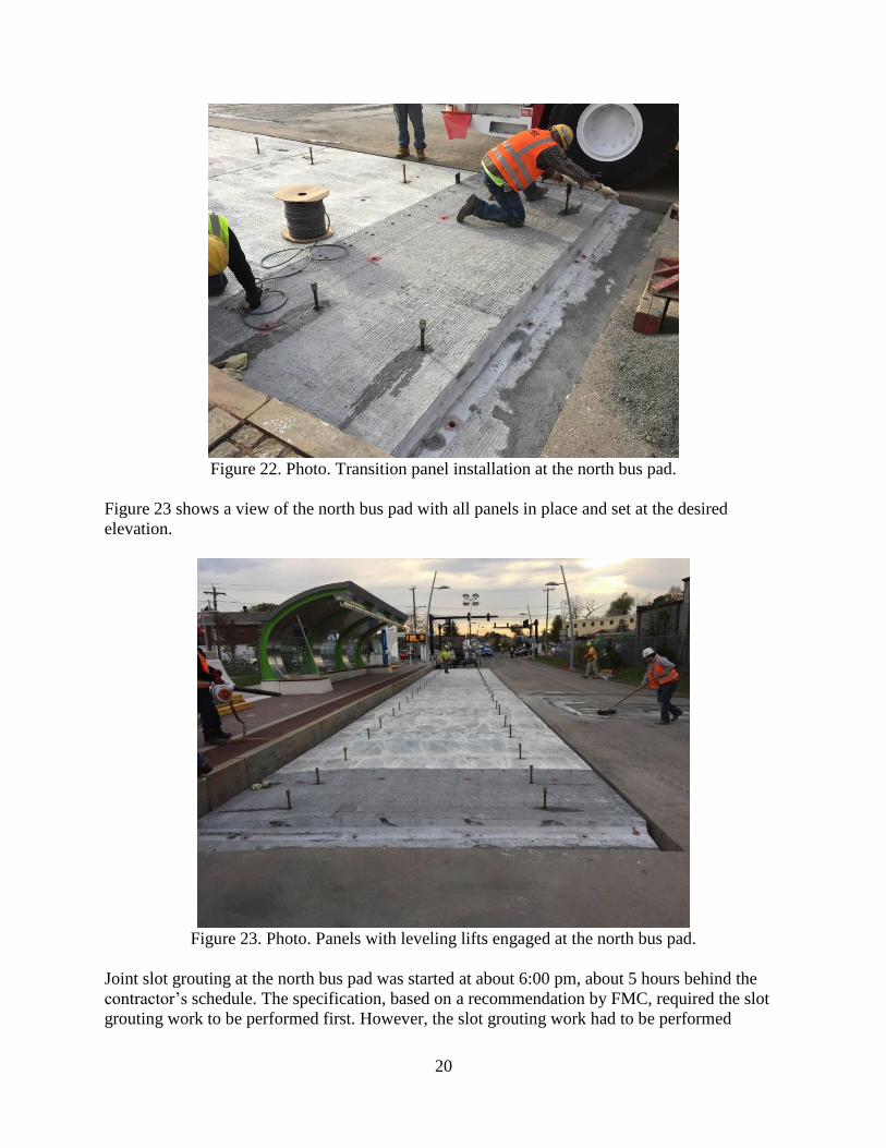
The placement of the last transition panel required extra effort. The available prepared area for
the last panel was too tight. As a result, Connecticut DOT allowed the contractor to trim the
thinner transition portion of the last panel by about 2 inches, as shown in figure 21. The
placement of the last transition panel is shown in figure 22. This panel had to be reset several
times due to the grading issues with the base, and the panel corner remained higher than the
adjacent AC pavement. The corner portion of the panel was later ground down to match the
surrounding AC pavement surface.
Figure 21. Photo. Trimming the transition panel at the north bus pad.
20
Figure 22. Photo. Transition panel installation at the north bus pad.
Figure 23 shows a view of the north bus pad with all panels in place and set at the desired
elevation.
Figure 23. Photo. Panels with leveling lifts engaged at the north bus pad.
Joint slot grouting at the north bus pad was started at about 6:00 pm, about 5 hours behind the
contractor’s schedule. The specification, based on a recommendation by FMC, required the slot
grouting work to be performed first. However, the slot grouting work had to be performed
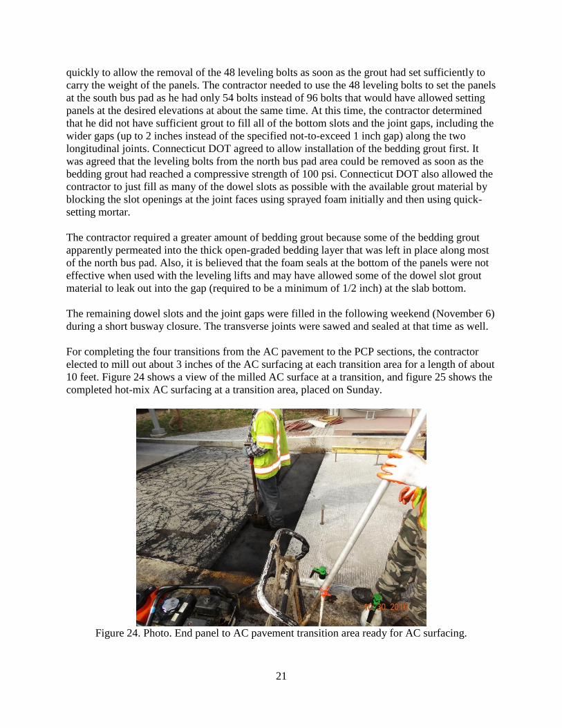
21
quickly to allow the removal of the 48 leveling bolts as soon as the grout had set sufficiently to
carry the weight of the panels. The contractor needed to use the 48 leveling bolts to set the panels
at the south bus pad as he had only 54 bolts instead of 96 bolts that would have allowed setting
panels at the desired elevations at about the same time. At this time, the contractor determined
that he did not have sufficient grout to fill all of the bottom slots and the joint gaps, including the
wider gaps (up to 2 inches instead of the specified not-to-exceed 1 inch gap) along the two
longitudinal joints. Connecticut DOT agreed to allow installation of the bedding grout first. It
was agreed that the leveling bolts from the north bus pad area could be removed as soon as the
bedding grout had reached a compressive strength of 100 psi. Connecticut DOT also allowed the
contractor to just fill as many of the dowel slots as possible with the available grout material by
blocking the slot openings at the joint faces using sprayed foam initially and then using quick-
setting mortar.
The contractor required a greater amount of bedding grout because some of the bedding grout
apparently permeated into the thick open-graded bedding layer that was left in place along most
of the north bus pad. Also, it is believed that the foam seals at the bottom of the panels were not
effective when used with the leveling lifts and may have allowed some of the dowel slot grout
material to leak out into the gap (required to be a minimum of 1/2 inch) at the slab bottom.
The remaining dowel slots and the joint gaps were filled in the following weekend (November 6)
during a short busway closure. The transverse joints were sawed and sealed at that time as well.
For completing the four transitions from the AC pavement to the PCP sections, the contractor
elected to mill out about 3 inches of the AC surfacing at each transition area for a length of about
10 feet. Figure 24 shows a view of the milled AC surface at a transition, and figure 25 shows the
completed hot-mix AC surfacing at a transition area, placed on Sunday.
Figure 24. Photo. End panel to AC pavement transition area ready for AC surfacing.
22
Figure 25. Photo. Completed AC surfacing at the end of the bus pad.
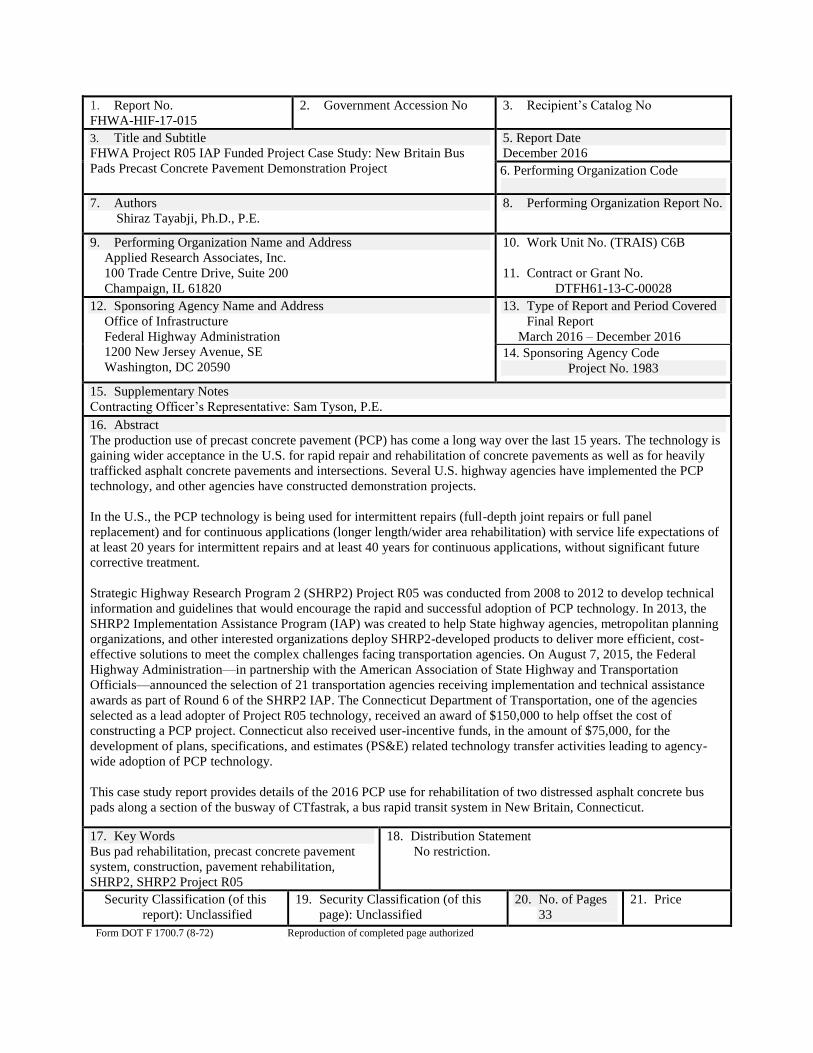
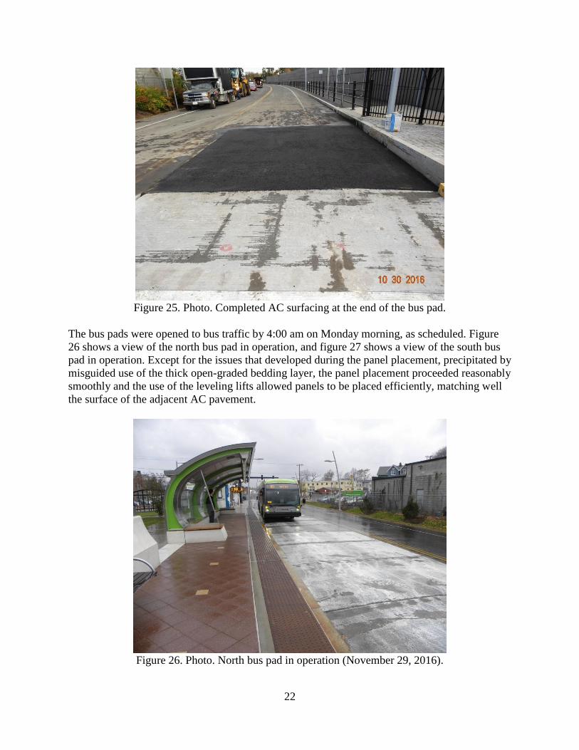
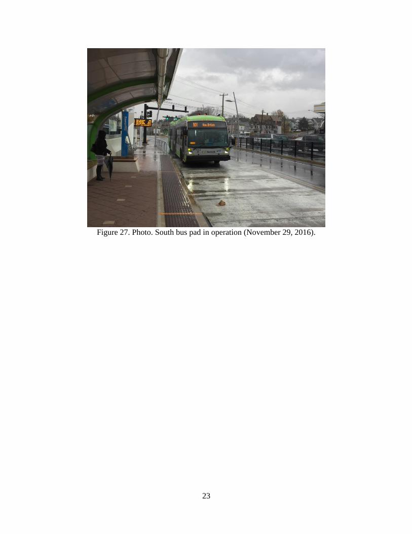
The bus pads were opened to bus traffic by 4:00 am on Monday morning, as scheduled. Figure
26 shows a view of the north bus pad in operation, and figure 27 shows a view of the south bus
pad in operation. Except for the issues that developed during the panel placement, precipitated by
misguided use of the thick open-graded bedding layer, the panel placement proceeded reasonably
smoothly and the use of the leveling lifts allowed panels to be placed efficiently, matching well
the surface of the adjacent AC pavement.
Figure 26. Photo. North bus pad in operation (November 29, 2016).
23
Figure 27. Photo. South bus pad in operation (November 29, 2016).

24
25
SUMMARY AND LESSONS LEARNED
The use of the PCP technology on a production pavement rehabilitation project was an important
step for Connecticut DOT. This was the first application of the PCP technology by Connecticut
DOT in a challenging setting where an important commuter busway traffic operation needed to
be maintained. In addition, Connecticut DOT expects to use the findings from this demonstration
project to refine specifications and plans for production use of PCP technology at future
pavement repair and rehabilitation projects along roadways with high traffic volumes, where
work can only be performed during nighttime lane closures and where treatments need to provide
long-life service.
Connecticut DOT prepared a debriefing report for this demonstration project, and the report
findings were discussed at an internal meeting held on November 29, 2016. The meeting was
attended by the pavement management and construction staff. The findings from the meeting and
the report, other than some of the construction-related items already discussed in the report, are
summarized below:
Design-related items:
o A generic PCP system will likely be implemented going forward to help bring in
competition, especially for the application of intermittent repairs.
o Connecticut DOT will not specify leveling lifts for intermittent joint repairs due to
the increased cost of such systems and limited work area associated with
intermittent joint repairs along composite pavements (concrete pavements
overlaid with AC).
o For intermittent repairs, Connecticut DOT expects to specify generic precast
panels, full-lane with and having standard panel lengths of 6, 8, and 10 feet. The
panels would be placed on the existing base, with provision for 3/4 inch thickness
of processed aggregate for base material lost during existing pavement removal.
o Connecticut DOT expects to allow the use of shims for their generic system to
avoid grout loss and estimation challenges.
o Connecticut DOT will refine the PCP specifications to be clear and to be
consistent with plans.
o The DOT will require more in-depth training, beyond pre-construction meetings,
for contractors and inspectors new to the PCP technology. For the bus pad project,
the contractor received training from FMC staff, but the level of training still
allowed for miscommunication regarding specification requirements.
o As part of project quality control/quality assurance documentation, the DOT will
require an inspector checklist for critical items to look for before and during
construction to avoid the delays that ensued on this project. On time-sensitive
projects, it is important to prevent improper construction activities at the start,
before it becomes too late to apply corrections.
Construction-related items:
o Grading and compaction of the wrongly used open-graded bedding layer was
time-consuming. A crushed stone base material that can be compacted adequately
26
should be required (as was required for this project) to make up for over-
excavated base material.
o A simpler and less costly method, such as shims, for setting panels at the right
elevation should be allowed for intermittent repairs and possibly for continuous
applications.
o The grouting process needs refinement to ensure the contractor is able to estimate
grout quantities correctly and grout material shortages do not develop at time-
sensitive projects.
The bus pad rehabilitation project in New Britain is considered a successful implementation of
the PCP technology on a production basis by an agency that had not constructed a PCP project
previously. The findings from this demonstration project will help Connecticut DOT to improve
plans and specifications as the DOT moves forward to production implementation of the PCP
technology for repair and rehabilitation of their older network of concrete surfaced and
composite pavements.
27
ACKNOWLEDGMENTS
The support of the following during the project planning phase and during data collection for this
report and the construction site visit is gratefully acknowledged:
Connecticut DOT staff:
o Steve Norton, Pavement Management Unit.
o John Henault, Transportation Supervising Engineer, Pavement Management Unit.
o Anthony Kwentoh, Transportation Supervising Engineer, Office of Construction.
Michael Baker International:
o J. Peter Maiorana, Project Manager.