ferrari 328 fuel filler hose replacement
TRANSCRIPT

Ferrari 328 Fuel Filler Hose ReplacementCarl Rose & Mark FoleyDecember 2003
The infamous fuel filler hose on the 308/328 series is a short piece of largerubber hose that connects the external fuel filler spout to the driver’s side gastank. Although replacement interval is not specified in the service schedule, overtime these hoses become brittle and can crack; subsequent leaks near hotengine are obvious fire hazard. Replacement procedure is relatively simple andinexpensive preventive maintenance.
[example shown is US-spec 1988.5 328 but 308/328 series is very similar]
Time required: about 1.5 hours
Tools required:
Jack and standsWheel blocksWheel lug nut socket [Snap-On #AS-281 7/8”aluminum-lined shown]Philips screwdriverSmall flat screwdriver¼” drive 6,7,10mm sockets with 3” extension and socket wrench(possibly: strap wrench)Vaseline to smear on hose ID
Special Tools required (optional):
Gates hose cutter part #91143 (about $12 from Carquest)

Parts required:
Fuel filler hose Ferrari # 114278 $38-40 (or alternatively Gates fuel line hose#23976 segment 2.25in diameter x 4in length available at NAPA or Carquest)Screw-type stainless hose clamps (2) for above hose (OEM Ferrari #12174790)
Wear goggles and gloves working underneath car. Remember you’reworking around fuel tank & gasoline so take intelligent precautions. Puttingdown a rug or towels will prevent sparks from dropped tools.
Block the front wheels. Open front hood and disconnect red battery plug.

Open rear window louvers and remove gas cap and spill guard (pulls over fillerneck):

Loosen left rear wheel bolts:

Jack and place stand under frame rail. Remove left rear wheel.
Remove fiberglass inner fender shield – held in place by four black Philipsscrews and three 10mm screws, all with large washers. My car had a slightlylonger Philips screw installed in the upper outer position (nearest to the outsidefender):

Maneuver shield out of wheelwell and set aside.
Fuel filler hose is hidden behind the oil cooler ducting. Remove the upper 10mmbolt and lower 10mm nut (stud on lower edge of oil cooler):


Gently drop the ducting down until you can easily access the two wiring harnessleads. Cylindrical black lower pulls directly out but the upper cream-colored multi-connector requires pressing tab on both sides:


Male part of the connector can then be removed from ducting bracket by carefullysequentially depressing the two snap-tabs on each side with small flatscrewdriver; the lower harness plug has sufficient free length that removal is notrequired. Alternatively loosen the harness bracket and allow to fall free. Pivot theducting towards the rear of the fender well.
Fuel filler hose is now accessible. Note how the screw clamps are positioned fartowards the inside to allow clearance for “s-bend” in the ductwork:
Taking care not to damage the oil cooler fins (consider taping over with piece ofcardboard to protect), loosen both clamps (7mm socket) and remove. Clampswere marked “Norma 50-70”, which I presume to be working diameter. Loosentwo 10mm nuts & 10mm sheet metal screws and remove the rectangular spout-locating bracket:

Remove clamp (6mm socket) from filler spout gold translucent overflow hose andtemporarily tuck this hose behind tank overflow hose:
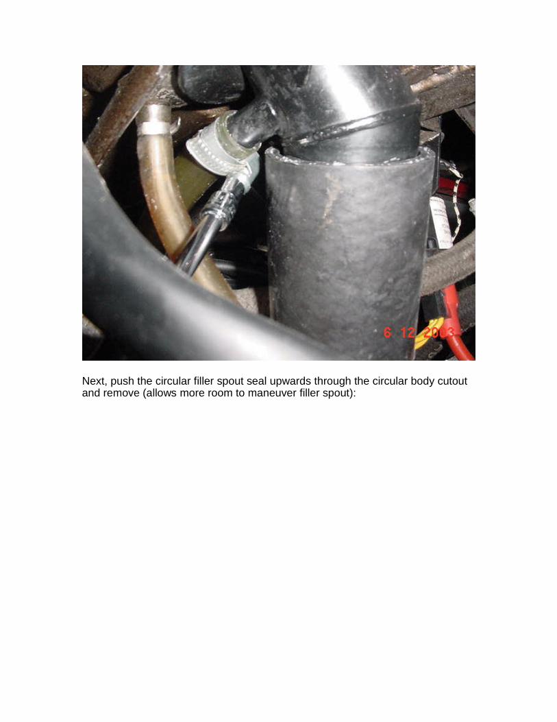
Next, push the circular filler spout seal upwards through the circular body cutoutand remove (allows more room to maneuver filler spout):

I was fortunate once clamps were removed I was able to twist filler hose quiteeasily. If your hose is firmly stuck a small strap wrench might break free or as lastresort simply cut off. Do not pry under the perimeter with screwdriver as couldcause a spark. If you elect to cut off be careful as both filler spout and tank collaras thin aluminum. Loosening the gas tank (two metal straps) will also allow a bitmore working space.
Push the filler spout up and outward as far as possible. Some determinedingenuity is required as the gap the hose actually bridges between the filler & gastank spouts is only about 1.5” and the hose itself is three times that long.Unfortunately the filler spout will not fit through the body to permit removal fromabove. I was successful in pushing the hose completely down onto the gas tankneck and with strong finger pressure clear one edge of the filler spout andprogressively “fold” the hose over and twist free. After hose is removed, removefiller spout. Clean both spout & tank necks to ensure good sealing.
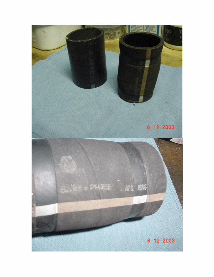
Factory hose on right is marked (indecipherable) dated “May 88”:
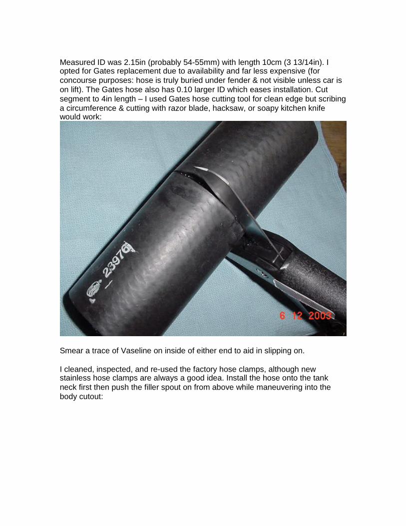
Measured ID was 2.15in (probably 54-55mm) with length 10cm (3 13/14in). Iopted for Gates replacement due to availability and far less expensive (forconcourse purposes: hose is truly buried under fender & not visible unless car ison lift). The Gates hose also has 0.10 larger ID which eases installation. Cutsegment to 4in length – I used Gates hose cutting tool for clean edge but scribinga circumference & cutting with razor blade, hacksaw, or soapy kitchen knifewould work:
Smear a trace of Vaseline on inside of either end to aid in slipping on.
I cleaned, inspected, and re-used the factory hose clamps, although newstainless hose clamps are always a good idea. Install the hose onto the tankneck first then push the filler spout on from above while maneuvering into thebody cutout:


Working from above, push the circular seal over the filler spout and work thelower section under the body edge:
Loosely install the filler hose screw clamps. Reinstall the filler spout overflowhose and tighten clamp. Replace the filler spout rectangular locating bracket andtighten two nuts & sheet metal screws.
Rotate the filler hose clamp screws until positioned as originally. Ensure eachclamp is not on the “lip” of either the spout or tank necks. Tighten in place:
Pivot the oil cooler ducting back. Fit over side intake then install upper 10mm boltand lower 10mm nut/washer over stud and tighten. Fit the male multi-connectorback into the bracket & snap female connector into place. Lower connector
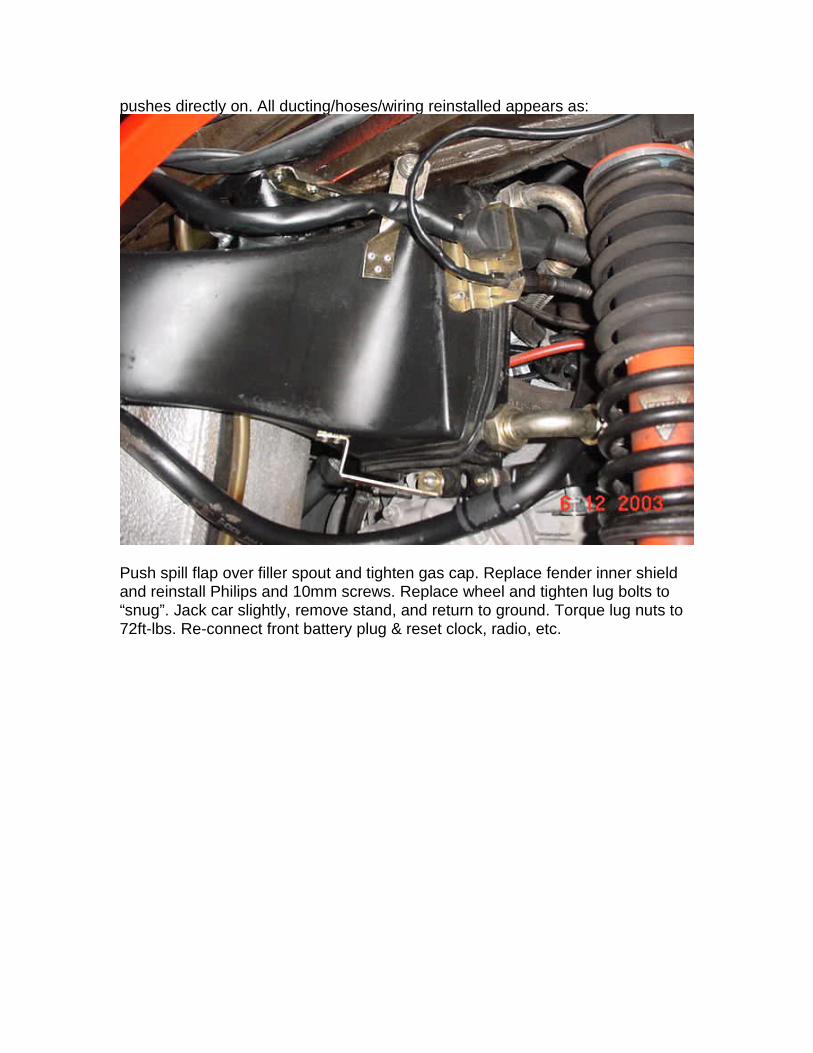
pushes directly on. All ducting/hoses/wiring reinstalled appears as:
Push spill flap over filler spout and tighten gas cap. Replace fender inner shieldand reinstall Philips and 10mm screws. Replace wheel and tighten lug bolts to“snug”. Jack car slightly, remove stand, and return to ground. Torque lug nuts to72ft-lbs. Re-connect front battery plug & reset clock, radio, etc.