fermi national accelerator laboratory - vlhcvlhc.org/cna/cna_report.pdf · estimate of heavy civil...
TRANSCRIPT

Report for: Estimate of Heavy Civil Underground Construction Costs for a Very Large Hadron Collider in Northern Illinois Prepared for: Fermi National Accelerator Laboratory Batavia, Illinois Prepared by: CNA Consulting Engineers Hatch-Mott-MacDonald September 4, 2001

VLHC Study i
Table of Contents List of Tables ............................................................................................. ii List of Figures ............................................................................................ ii Executive Summary .......................................................................................1 1 Introduction ........................................................................................3
1.1 Project Description ........................................................................ 3 1.2 Limitations.................................................................................. 3 1.3 Acknowledgements......................................................................... 3
2 Geologic Conditions................................................................................5 2.1 Sources of Information .................................................................... 5 2.2 Geological Information .................................................................... 5
2.2.1 Overburden..........................................................................5 2.2.2 Silurian ...............................................................................5 2.2.3 Maquoketa...........................................................................6 2.2.4 Galena—Platteville .................................................................6 2.2.5 Ancell ................................................................................6 2.2.6 Prairie du Chien.....................................................................6 2.2.7 Sandwich Fault......................................................................6 2.2.8 Des Plaines Disturbance............................................................7 2.2.9 Groundwater Conditions ...........................................................7
2.3 Rock Condition Categories ................................................................ 7 3 Assumptions, Construction Conditions and Estimated Heavy Civil Construction Costs .....9
3.1 Cost Estimate Methodology ............................................................... 9 3.2 Shafts ........................................................................................ 9 3.3 Caverns and Drill & Blast Tunnel Construction ........................................ 10
3.3.1 Excavation......................................................................... 10 3.3.2 Primary Support Requirements Based On Empirical Methods................ 10 3.3.3 Special Components .............................................................. 11 3.3.4 Groundwater Control............................................................. 12
3.4 Tunneling .................................................................................. 12 3.4.1 TBM Type A, Rock Conditions 1,3, and 9. ...................................... 13 3.4.2 TBM Type B, Rock Conditions 2,5,6,7,8,10,11................................. 14 3.4.3 TBM Type C, Rock Conditions 12,13,14, and Declines ........................ 14
3.5 Site Risers .................................................................................. 14 3.6 Portals ...................................................................................... 14 3.7 Miscellaneous .............................................................................. 15 3.8 Rock Disposal .............................................................................. 15 3.9 Indirect Costs .............................................................................. 15 3.10 Contingency................................................................................ 15 3.11 Price Escalation ........................................................................... 16 3.12 EDIA......................................................................................... 16 3.13 Items not Covered in the Estimate ...................................................... 16 3.14 Cost Estimate Summary .................................................................. 17
4 Heavy Civil Underground Construction Schedule ............................................. 18 Bibliography ............................................................................................. 19 Figures Appendix A—Listing of Project Components Appendix B—Notes from Observations and Discussions Appendix C—Rock Type Summaries Appendix D TBM Tunnel Assumptions and Cost Estimating Output Appendix E TBM Tunnel Assumptions and Cost Estimating Output (Not Used)

VLHC Study ii
List of Tables Table 1—Rock Conditions Categories. ................................................................. 8
Table 2—Q Ratings for Each Rock Condition Category. ............................................. 10
Table 3—Rockbolt Spacing & Shotcrete Thickness vs. Rock Quality. .............................. 11
Table 4—Rock & Tunneling Conditions Groupings. .................................................. 12
Table 5—Cost Estimate Summary, Values in Millions of 2001 Dollars. ............................ 17
Table 6—Summary of Underground Construction Durations. ....................................... 18
List of Figures Figure 1.1—Site Plan
Figure 2.1—North Inclined Ring—Rock Conditions
Figure 2.2—North Inclined Ring—Lampshade, Rock Conditions
Figure 2.3—North Flat Ring—Rock Conditions
Figure 2.4—North Flat Ring—Lampshade, Rock Conditions
Figure 2.5—South Inclined Ring—Rock Conditions
Figure 2.6—South Inclined Ring—Lampshade, Rock Conditions
Figure 3.1—Rockbolt Spacing vs. Q
Figure 3.2—Shotcrete Spacing vs. Q
Figure 3.3—North Inclined Ring—Rock Conditions and TBM Types
Figure 3.4—North Flat Ring—Rock Conditions and TBM Types
Figure 3.5—South Inclined Ring—Rock Conditions and TBM Types
Figure 3.6—Turner Building Cost Index
Figure 3.7-Cost Breakdown
Figure 4.1—North Inclined Ring—Rock Conditions, TBM Types, and Schedule
Figure 4.2—North Flat Ring—Rock Conditions, TBM Types, and Schedule
Figure 4.3—South Inclined Ring—Rock Conditions, TBM Types, and Schedule

VLHC Study 1
Executive Summary The team of CNA Consulting Engineers and the Toronto office of Hatch-Mott-MacDonald developed cost estimates for heavy civil underground construction of a staged Very Large Hadron Collider (VLHC) project located tangent to the Tevatron at FermiLab. Three alignment alternatives and two main beam tunnel diameters were included. The cost estimates include heavy civil underground construction that produces stable underground excavations, but excludes outfitting. FermiLab provided detailed project descriptions and so-called “lampshades” that defined the subsurface geologic formations encountered by the three tunnel alternatives.
Ten principal tasks were conducted. A brief summary of each is provided below. 1. Review existing geologic data, using published geologic resources—We used the reports
listed in the Bibliography to confirm the location and extent of the geologic formations in the study areas. In addition, we formed a conceptual model of the rock conditions present, and identified fourteen rock condition types, which are summarized in the table under item 4 below.
2. Observe pertinent geologic exposures in the field—After review of the available and pertinent geologic exposures, this task was limited to an underground tour of the NuMI project construction, and the a surface and underground tour to the Conco Western Stone Quarry in North Aurora, Il. Both visits were very useful in assessing the underground construction conditions for the VLHC components near FermiLab.
3. Quantify all major underground construction components of the VLHC—Underground construction components of the VLHC project include the main beamline tunnel, many caverns of varying size and shape, straight and bypass tunnels, portals for the equipment tunnels, injection ramp connections to the existing Tevatron, a magnet installation ramp on the far side from FermiLab, major experiment installation shafts, access shafts, emergency egress and ventilation shafts, site risers, and utility penetrations. Each of these 300-plus components is documented in Appendix A. This report does not include the near-surface structures necessary at the connection from the existing Tevatron to the injection ramps.
4. Categorize anticipated tunneling conditions for major geologic units and contacts between major units—For estimating the cost of cavern construction, an NGI Q rating was estimated for each of the fourteen rock conditions identified in Task 1 above. Q values ranged from a minimum of 0.33 to a maximum of 33.75, with cavern rock support and construction conditions depending upon the Q rating.
For estimating tunnel construction costs, the fourteen rock conditions were assigned to three tunneling conditions types, as shown in Table 4 on page 12. The finished diameter of the tunnels is either 12 ft or 16 ft, and the TBM’s are capable of tunnel drives 4844 meters long, equivalent to the shaft spacing. At end of each drive the TBM could be accessed for reconditioning. TBM Type A, for rock conditions 1, 3, and 9 is used in the best rock conditions where minimal ground support and water control is required. TBM Type B, an open TBM with finger shield, is used for rock conditions 2, 5, 6, 7, 8, 10, and 11 where more ground support and water control is required. TBM Type C, a sealed TBM, is used for rock conditions 12, 13, 14, and the injection ramps where water inflow is great enough to require immediate sealing of the tunnel. The ground support, grouting and final lining methods were selected to produce stable excavations with less than 50 gpm average water inflow per mile of tunnel, including the inflow from caverns and shafts. FermiLab will determine the cost of project outfitting (e.g. electrical,
VLHC Study 2
ventilation, cooling, cranes, pumping, lighting, etc.).
5. Develop a bottoms-up estimate for each project component—Major cost drivers, e.g. the TBM tunnels, shafts and caverns, were estimated by bottoms-up methods. The design concepts for minor items, e.g.portal structures, site risers and utility penetrations, were not sufficiently developed to warrant a bottoms-up approach.
6. Assemble costs from the kit-of-parts to estimate the cost of three tunnel alternatives (North—Flat, North—Inclined, and South—Inclined) and two tunnel diameters (12 ft and 16 ft finished)—Completed, see Item 9 below.
7. Provide cost ranges or contingency values appropriate to the understanding of ground conditions and design maturity achieved—A 25 percent contingency has been included as a line item in the cost estimate, which is adequate to cover moderate changes in geologic conditions, design, bidding and construction. It is not adequate for major changes like changes in size, length, and number of tunnels, caverns, or shafts. The costs also include 17.5 percent EDIA costs, including site investigation, professional design services, project management and institutional costs.
8. Estimate heavy civil construction duration for each major project component—TBM tunnel construction costs, depending upon the option, are roughly two to eight times shaft costs and four to seven times cavern costs. Hence, TBM tunnels are the major cost drivers and the longest duration elements of VLHC construction. Sequence and duration for TBM drives and TBM contracts were developed for each option.
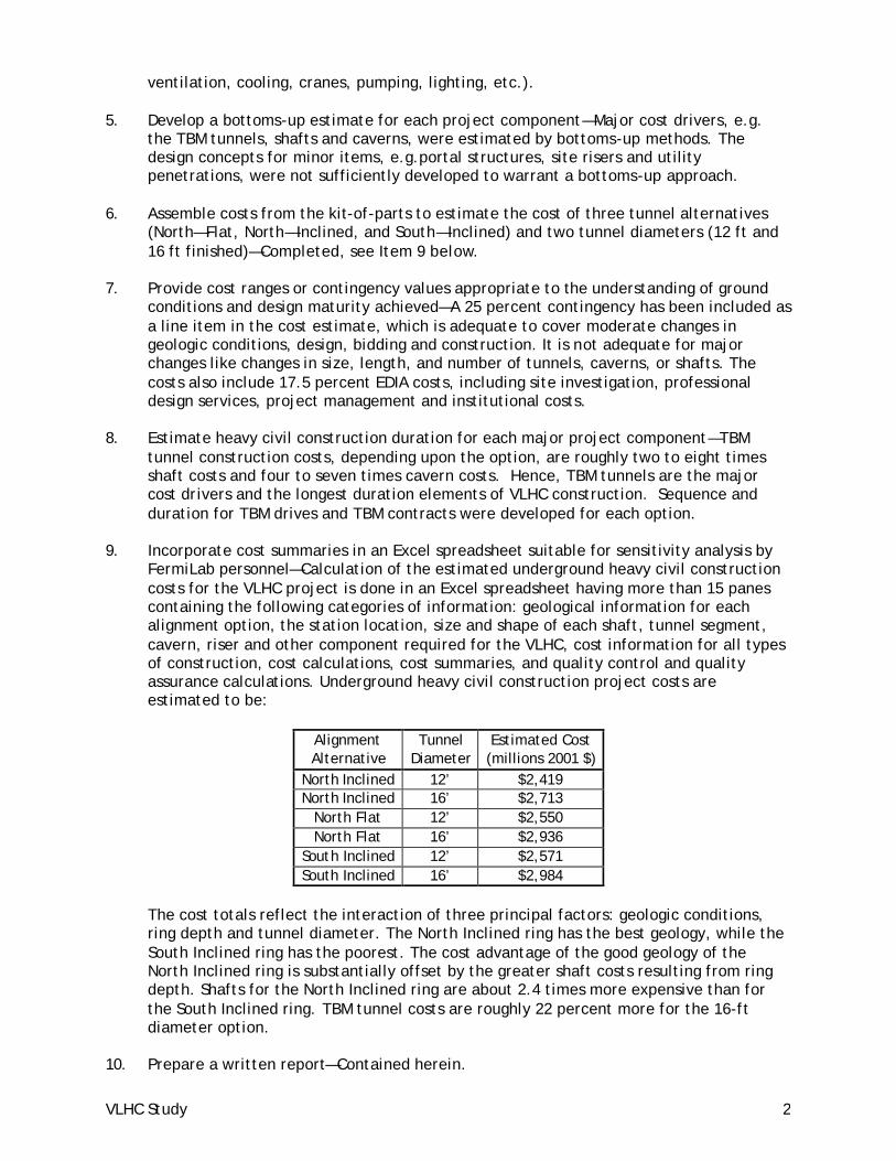
9. Incorporate cost summaries in an Excel spreadsheet suitable for sensitivity analysis by FermiLab personnel—Calculation of the estimated underground heavy civil construction costs for the VLHC project is done in an Excel spreadsheet having more than 15 panes containing the following categories of information: geological information for each alignment option, the station location, size and shape of each shaft, tunnel segment, cavern, riser and other component required for the VLHC, cost information for all types of construction, cost calculations, cost summaries, and quality control and quality assurance calculations. Underground heavy civil construction project costs are estimated to be:
Alignment Alternative
Tunnel Diameter
Estimated Cost (millions 2001 $)
North Inclined 12’ $2,419 North Inclined 16’ $2,713
North Flat 12’ $2,550 North Flat 16’ $2,936
South Inclined 12’ $2,571 South Inclined 16’ $2,984
The cost totals reflect the interaction of three principal factors: geologic conditions, ring depth and tunnel diameter. The North Inclined ring has the best geology, while the South Inclined ring has the poorest. The cost advantage of the good geology of the North Inclined ring is substantially offset by the greater shaft costs resulting from ring depth. Shafts for the North Inclined ring are about 2.4 times more expensive than for the South Inclined ring. TBM tunnel costs are roughly 22 percent more for the 16-ft diameter option.
10. Prepare a written report—Contained herein.
VLHC Study 3
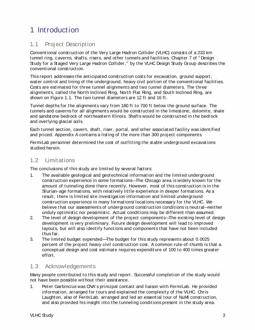
1 Introduction
1.1 Project Description Conventional construction of the Very Large Hadron Collider (VLHC) consists of a 233 km tunnel ring, caverns, shafts, risers, and other tunnels and facilities. Chapter 7 of “Design Study for a Staged Very Large Hadron Collider,” by the VLHC Design Study Group describes the conventional construction.
This report addresses the anticipated construction costs for excavation, ground support, water control and lining of the underground, heavy civil portion of the conventional facilities. Costs are estimated for three tunnel alignments and two tunnel diameters. The three alignments, called the North Inclined Ring, North Flat Ring, and South Inclined Ring, are shown on Figure 1.1. The two tunnel diameters are 12 ft and 16 ft.
Tunnel depths for the alignments vary from 180 ft to 700 ft below the ground surface. The tunnels and caverns for all alignments would be constructed in the limestone, dolomite, shale and sandstone bedrock of northeastern Illinois. Shafts would be constructed in the bedrock and overlying glacial soils.
Each tunnel section, cavern, shaft, riser, portal, and other associated facility was identified and priced. Appendix A contains a listing of the more than 300 project components.
FermiLab personnel determined the cost of outfitting the stable underground excavations studied herein.
1.2 Limitations The conclusions of this study are limited by several factors: 1. The available geological and geotechnical information and the limited underground
construction experience in some formations—The Chicago area is widely known for the amount of tunneling done there recently. However, most of this construction is in the Silurian-age formations, with relatively little experience in deeper formations. As a result, there is limited site investigation information and limited underground construction experience in many formations/locations necessary for the VLHC. We believe that our assessments of underground construction conditions is neutral—neither unduly optimistic nor pessimistic. Actual conditions may be different than assumed.
2. The level of design development of the project components—The existing level of design development is very preliminary. Future design development will lead to improved layouts, but will also identify functions and components that have not been included thus far.
3. The limited budget expended—The budget for this study represents about 0.0025 percent of the project heavy civil construction cost. A common rule-of-thumb is that a conceptual design and cost estimate requires expenditure of 100 to 400 times greater effort.
1.3 Acknowledgements Many people contributed to this study and report. Successful completion of the study would not have been possible without their assistance. 1. Peter Garbincius was CNA’s principal contact and liaison with FermiLab. He provided
information, arranged for tours and explained the complexity of the VLHC. Chris Laughton, also of FermiLab, arranged and led an essential tour of NuMI construction, and also provided his insight into the tunneling conditions present in the study area.
VLHC Study 4
2. Robert Bauer of the Illinois State Geological Society provided invaluable assistance by serving as a guide to the publications, boring logs and rock core available through the ISGS. In addition, his previous and ongoing work on tunneling and underground construction in northern Illinois was the foundation of this study.
3. Peter Conroy, formerly of Harza Engineering, freely shared his underground construction experience and knowledge of northern Illinois geology. He also provided insightful and constructive comments on a draft version of the report.
4. Brian Garrod of HMM produced the TBM production rates and cost estimates. 5. Charles Nelson, Bruce Wagener, Bob Martin and Lee Petersen conducted the ground
conditions evaluations and cost estimating done by CNA Consulting Engineers.

VLHC Study 5
2 Geologic Conditions
2.1 Sources of Information Geologic information used as the basis for the cost estimate was obtained from the following sources. We have not referenced these sources in the report, but the Bibliography contains their listing: 1. Documents listed in the references at the end of this report. 2. Discussions with Robert Bauer, Illinois State Geological Survey and Peter Conroy,
consulting engineer. 3. A visit to the Conco Western Stone Quarry in North Aurora, Il. 4. A review of available rock core. Appendix B contains notes from the discussions, quarry visit, and rock core review.
2.2 Geological Information For the purposes of the cost estimate, the assumed properties of the geological materials that will be encountered during the excavations are described in the sections below and are summarized in table in Appendix C. These assumptions are based on available reports, examination of core, a visit to the Conco Western Stone Quarry in North Aurora, and discussions with other researchers.
2.2.1 Overburden
Construction will take place in layers of glacial soils ranging in thickness from 25 to 400 feet in some areas. Much of Northern Illinois topped with glacial tills, lacustrine silts and clays, and outwash sands and gravels. A large majority of the overburden is well graded, over- consolidated glacial till consisting of silt, sand, gravel, cobbles, and boulders in a clay matrix.
Groundwater is present in glacial soils. Significant groundwater inflows will occur in sand and gravel layers.
2.2.2 Silurian
The Silurian group is divided into the Racine, Joliet, Kankakee and the Elwood formations.
The Racine formation ranges from 0 to 360 feet thick in some areas of Northern Illinois. The Racine is mostly a dolomite largely vuggy to coarsely vuggy, medium grained, light gray to white in color. Some of the rock is impure varying from moderately silty to very silty containing chert and scattered nodules.
The Joliet formation has two members, the Romeo and Margraff, and is present in northeastern Illinois. The Romeo member is 18 to 34 feet thick and is a light gray to white vuggy medium bedded dolomite. The Margraff member is 9 to 51 feet thick and is divided into an upper and lower zone. The upper zone is a fine grain dense dolomite containing a few shale partings and porous chert nodules. The lower zone is silty with closely spaced dolomitic laminae.
The Kankakee formation ranges from 9 to 80 feet and has wavy beds of fine to medium grained dolomite layers 1 to 3 inches thick separated by greenish gray shale.
The Elwood is 20 to 30 feet thick where not eroded and is primarily a cherty dolomite with nodules in layers up to 3 inches thick.
VLHC Study 6
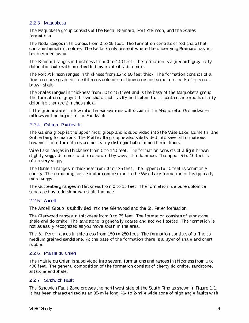
2.2.3 Maquoketa
The Maquoketa group consists of the Neda, Brainard, Fort Atkinson, and the Scales formations.
The Neda ranges in thickness from 0 to 15 feet. The formation consists of red shale that contains hematitic oolites. The Neda is only present where the underlying Brainard has not been eroded away.
The Brainard ranges in thickness from 0 to 140 feet. The formation is a greenish gray, silty dolomitic shale with interbedded layers of silty dolomite.
The Fort Atkinson ranges in thickness from 15 to 50 feet thick. The formation consists of a fine to coarse grained, fossiliferous dolomite or limestone and some interbeds of green or brown shale.
The Scales ranges in thickness from 50 to 150 feet and is the base of the Maquoketa group. The formation is grayish brown shale that is silty and dolomitic. It contains interbeds of silty dolomite that are 2 inches thick.
Little groundwater inflow into the excavations will occur in the Maquoketa. Groundwater inflows will be higher in the Sandwich
2.2.4 Galena—Platteville
The Galena group is the upper most group and is subdivided into the Wise Lake, Dunleith, and Guttenberg formations. The Platteville group is also subdivided into several formations, however these formations are not easily distinguishable in northern Illinois.
Wise Lake ranges in thickness from 0 to 140 feet. The formation consists of a light brown slightly vuggy dolomite and is separated by wavy, thin laminae. The upper 5 to 10 feet is often very vuggy.
The Dunleith ranges in thickness from 0 to 125 feet. The upper 5 to 10 feet is commonly cherty. The remaining has a similar composition to the Wise Lake formation but is typically more vuggy.
The Guttenberg ranges in thickness from 0 to 15 feet. The formation is a pure dolomite separated by reddish brown shale laminae.
2.2.5 Ancell
The Ancell Group is subdivided into the Glenwood and the St. Peter formation.
The Glenwood ranges in thickness from 0 to 75 feet. The formation consists of sandstone, shale and dolomite. The sandstone is generally coarse and not well sorted. The formation is not as easily recognized as you move south in the area.
The St. Peter ranges in thickness from 150 to 250 feet. The formation consists of a fine to medium grained sandstone. At the base of the formation there is a layer of shale and chert rubble.
2.2.6 Prairie du Chien
The Prairie du Chien is subdivided into several formations and ranges in thickness from 0 to 400 feet. The general composition of the formation consists of cherty dolomite, sandstone, siltstone and shale.
2.2.7 Sandwich Fault
The Sandwich Fault Zone crosses the northwest side of the South Ring as shown in Figure 1.1. It has been characterized as an 85-mile long, ½- to 2-mile wide zone of high angle faults with

VLHC Study 7
maximum displacements of 800 ft. The maximum displacements occur near where the fault crosses the South Ring. The south side of the fault is upthrown throughout most of the fault zone. Most of the fault zone is concealed by surficial deposits. The Illinois Geological Survey was not aware of any rock cores in the fault zone.
2.2.8 Des Plaines Disturbance
The Des Plaines Disturbance is located on the southeast side of the South Ring as shown in Figure 1.1. It has been characterized as a 5-mile diameter zone of faulting. Within the disturbance, rock has been found to be faulted, tilted, brecciated, and located as much as 800 feet from its expected position. It is believed that the Disturbance was caused by impact from an extraterrestrial body.
2.2.9 Groundwater Conditions
Previous investigations identify three groundwater regimes—the Drift and Upper Bedrock Aquifer, Upper Ordovician Aquitard, and Deep Bedrock Aquifer.
The Drift and Upper Bedrock Aquifer was assumed to consist of the drift and upper 75 ft of the bedrock surface. It was assumed to have a higher permeability due to the presence of the drift and higher degree of weathering.
The Upper Ordovician Aquitard was assumed to consist of the relatively low permeability Maquoketa and the Galena—Platteville. The low permeability is due to the rock’s high shale, limestone, and dolomite content and its tight jointing.
The Deep Bedrock Aquifer was assumed to consist of the relatively high permeability Ancell and Prairie Du Chien. The higher permeability is due to the presence of higher permeability sandstones.
Rock in the Sandwich Fault and Des Plaines Disturbance was assumed to have a higher permeability due to increased faulting and fracturing.
For the purposes of the cost estimate, all geologic formations are assumed to be below the water table. Variations in the expected water conditions were assumed to be due to the relative permeabilities of the formations. Recent studies indicate water levels are below the tunnels in some areas, but a shift in water usage from deep wells to surface sources suggests water levels are rising, but this is uncertain. For the purposes of the cost estimate, all geologic formations are assumed to be below the water table.
2.3 Rock Condition Categories Based on the information in Section 2.1, fourteen rock condition categories were determined to be present along the various alignments. The rock in each category is assumed to be a member of the same geologic formation and have similar rock properties, weathering, and water conditions. These fourteen rock condition categories were then grouped into three tunneling condition categories, discussed in Section 3.4.
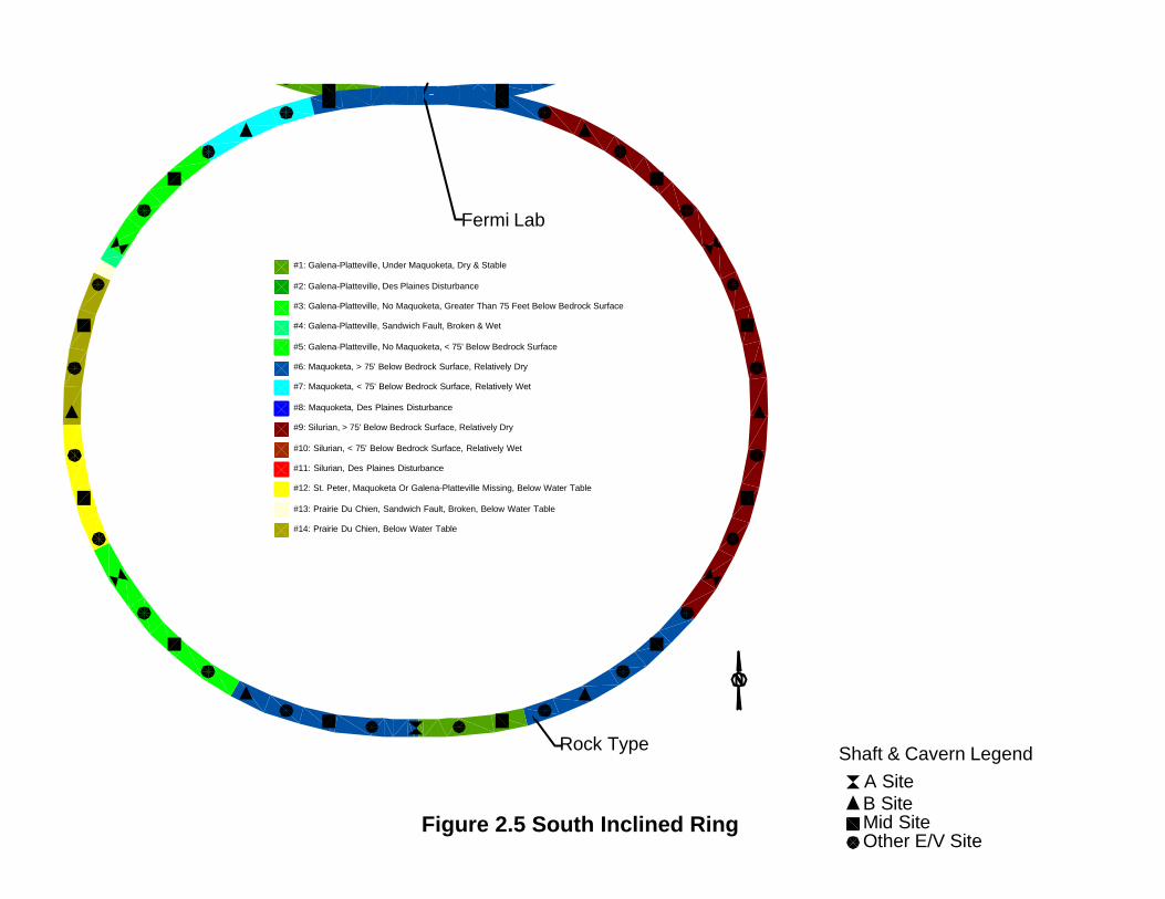
Rock condition categories are listed in table below. Distribution of these categories on each alignment is shown in the plan views and lampshades in Figures 2.1 through 2.6. The distinctions between the categories were based on the following: 1. Geologic formation. Each formation has its own characteristics, rock properties, and
groundwater permeability. 2. Within or below 75 ft of the bedrock surface. Rock less than 75 ft below the rock
surface was considered to be more weathered and have higher groundwater permeability than deeper rocks.

VLHC Study 8
3. Within or outside of 1 mile of the Sandwich Fault. Rock near the Sandwich Fault was considered to be more fractured and have higher groundwater permeability than rock away from the fault.
4. Within or outside the Des Plaines Disturbance. Rock near the Des Plaines Disturbance was considered to be more fractured and have higher groundwater permeability than rock away from the fault.
# Category Description 1 Galena—Platteville, Under Maquoketa, Dry and Stable 2 Galena—Platteville, Des Plaines Disturbance 3 Galena—Platteville, No Maquoketa, Greater Than 75 Feet Below Bedrock Surface 4 Galena—Platteville, Sandwich Fault Broken and Wet 5 Galena—Platteville, No Maquoketa, Less Than 75 Feet Below Bedrock Surface 6 Maquoketa, Greater Than 75 Feet Below Bedrock Surface, Relatively Dry 7 Maquoketa, Less Than 75 Feet Below Bedrock Surface, Wetter 8 Maquoketa, Des Plaines Disturbance 9 Silurian, Greater Than 75 Feet Below Bedrock Surface, Dry 10 Silurian, Less Than 75 Feet Below Bedrock Surface, Wet 11 Silurian, Des Plaines Disturbance 12 St. Peter, Maquoketa or Galena—Platteville Missing, Below Water Table 13 Prairie du Chien, Sandwich Fault, Broken, Below Water Table 14 Prairie du Chien, Below Water Table
Table 1—Rock Conditions Categories.

VLHC Study 9
3 Assumptions, Construction Conditions and Estimated Heavy Civil Construction Costs This chapter describes the construction conditions and assumptions made for each construction component and summarizes the costs. The following sections describe the major components included in the estimate, which are shafts, caverns, TBM tunnels, drill and blast tunnels, risers, portals, and miscellaneous. Section 3.8 describes the assumptions made for rock disposal. Sections 3.9 and 3.11 describe the construction contingency and price escalation. Section 3.12 describes the cost assumptions made for EDIA. Section 3.13 describes the items not included in the estimate. Section 3.14 contains the cost estimate summary.
3.1 Cost Estimate Methodology Calculation of the estimated construction costs for the VLHC project is done in an Excel spreadsheet having more than 15 panes. These panes contain the following categories of information: 1. Geological information for each alignment option, in the form of so-called
“lampshades,” which provide the elevation formation contacts, 2. The station location, size and shape of each shaft, tunnel segment, cavern, riser and
other component required for the VLHC, 3. Unit prices for all types of construction, 4. Cost calculations, with one pane per option, 5. Cost summaries, and 6. Quality control and quality assurance calculations. This spreadsheet approach was developed so that FermiLab personnel could investigate the cost of other options by varying option parameters. For example, if a shallower North Inclined Ring was of interest, the cost could be determined by changing the parameter that controlled ring depth. The spreadsheet would recalculate the shaft depths, rock types, rock quality, support requirements, etc. and provide a new cost.
This objective was realized for all VLHC components except the tunnels. The process of assigning each rock condition type to one of three TBM categories has not been automated. This process is documented in Section 3.4 Tunneling. The difficulty arises because of the additional constraints: 1. The worst ground condition in an alignment interval sets the TBM category, 2. TBM drives must start and end at shafts, 3. TBM drives have minimum and maximum lengths, and 4. The construction schedule also constrains TBM drives.
3.2 Shafts The current VLHC layout requires mostly round shafts, with a few rectangular shafts in selected locations. With a few exceptions, the shafts service the various A-, B-, Mid-, and E/V sites. The remaining shafts are at the special purpose caverns, e.g. experimental, beam-stop, KMPS, RFKT. Most shafts extend from the ground surface to the main beam tunnel invert, but a few service special needs and are shallower or deeper than the tunnel invert.
The spreadsheet determines the thickness of soil and rock in each shaft. Shaft soil excavation is by an appropriately sized loader, and rock excavation is by drill and blast means. All rock types are considered to be the same for shaft sinking purposes. Initial support, grouting, concrete lining and water control are provided in both soil and rock.

VLHC Study 10
3.3 Caverns and Drill & Blast Tunnel Construction
3.3.1 Excavation
The cost estimate assumes that all caverns are excavated by drill and blast methods, using smoothwall blasting procedures to maintain the integrity of the rock. All caverns are assumed to be excavated using one 6-meter top heading, and zero or more benches depending upon total cavern height. The top headings are drilled horizontally and require longer cycle times due to the installation of roof rockbolts and shotcrete. Cavern benches are drilled vertically and have shorter cycle times, due to less rock support.
3.3.2 Primary Support Requirements Based On Empirical Methods
The primary support requirements have been assessed using the method developed by the Norwegian Geotechnical Institute (NGI, 1984; Barton and Grimstad, 1993). The method, developed from a large number of case histories, relates the required primary support to the rock mass quality, Q. The Q value is determined from the frequency, orientation, roughness and infilling of the discontinuities, the groundwater, and in situ stress conditions. The Q rating is computed from:
SRFJw
xJaJr
xJn
RQDQ =
where: 1. RQD = Rock Quality Designation 2. Jn = Joint set number 3. Jr = Joint roughness number 4. Ja = Joint alteration number 5. Jw = Joint water reduction factor 6. SRF = Stress Reduction Factor Assumed Q ratings for each of the fourteen rock condition types are illustrated in table below.
Category Description RQD Jn Jr Ja Jw SRF Q
Galena—Platteville, Under Maquoketa, Dry and Stable 90 4 3 4 1 0.5 33.75 Galena—Platteville, Des Plaines Disturbance 60 9 0.5 2 0.66 2.5 0.44 Galena—Platteville, No Maquoketa, Greater Than 75 Feet Below Bedrock 90 4 3 4 0.66 0.5 22.28 Galena—Platteville, Sandwich Fault Broken and Wet 60 9 0.5 2 0.66 2.5 0.44 Galena—Platteville, No Maquoketa, Less Than 75 Feet Below Bedrock 90 4 3 4 0.66 1 11.14 Maquoketa, Greater Than 75 Feet Below Bedrock Surface, Relatively Dry 85 4 2 4 1 1 10.63 Maquoketa, Less Than 75 Feet Below Bedrock Surface, Wetter 85 4 2 4 0.66 1 7.01 Maquoketa, Des Plaines Disturbance 60 9 0.5 2 0.66 2.5 0.44 Silurian, Greater Than 75 Feet Below Bedrock Surface, Dry 90 4 3 4 1 0.5 33.75 Silurian, Less Than 75 Feet Below Bedrock Surface, Wet 90 4 3 4 0.66 0.5 22.28 Silurian, Des Plaines Disturbance 60 9 0.5 2 0.66 2.5 0.44 St. Peter, Maquoketa or Galena—Platteville Missing, Below Water Table 70 4 3 1 0.5 10 2.63 Prairie du Chien, Sandwich Fault, Broken, Below Water Table 60 9 0.5 2 0.5 2.5 0.33 Prairie du Chien, Below Water Table 90 4 3 1 0.5 7 4.82
Table 2—Q Ratings for Each Rock Condition Category.

VLHC Study 11
The highest Q value (33.75) is for the Galena-Platteville and Silurian formations where found greater than 75 feet below the bedrock surface. These rock condition types have higher than average RQD; two joint sets; rough and irregular, undulating joints; low-friction clay mineral coatings; dry or minor water inflow; and tight structure. The lowest common Q value (0.44) are for the Galena-Platteville formation in the vicinity of the Des Plaines disturbance, the same formation in the vicinity of the Sandwich Fault, the Maquoketa shale in the vicinity of the Des Plaines disturbance, and the Silurian dolomites in the vicinity of the Des Plaines disturbance. By comparison, these rocks have lower RQD; three joint sets; slickensided, planar joints; medium water inflow; and weakness zones containing clay. The lowest Q value is for the Prairie du Chien formation in the vicinity of the Sandwich Fault, below the water table. This formation is rated lower than the more common formation because of greater water inflow.
These Q values are used to determine rockbolt spacing and shotcrete thickness, while other methods are be used to estimate the rockbolt length. Cavern rockbolt length is based on one of Lang’s (1961) rules of thumb. The minimum rockbolt length is: 1. one-half the span for spans less than 6 meters, and 2. one-fourth the span for spans of 18 meters to 30 meters. Figure 3.1 and Figure 3.2 show the Q rating relationships for rockbolt spacing and shotcrete thickness, respectively. The numerical values for rockbolt spacing and shotcrete thickness are:
Q Rating Rockbolt Spacing (m)
Shotcrete Thickness
(mm) 0.33 1.54 220 0.44 1.61 211 2.63 2.01 154 4.82 2.15 135 7.01 2.23 123 10.63 2.32 110 11.14 2.34 108 22.28 2.49 86 33.75 2.58 73
Table 3—Rockbolt Spacing & Shotcrete Thickness vs. Rock Quality.
The estimate assumes that the cavern sidewalls and endwalls require rock support equal to 40 percent of the roof support cost.
3.3.3 Special Components
Six tunnel segments (three each side of FermiLab) require cavern-like construction. These are: 1. Injection-Straight interface—A cavern-like excavation is required where the injection
ramp forms a wye with the main beam tunnel. The geometry of this wye depends on the final location and orientation of the ring. For the purposes of this estimate, the interface is assumed to be 7.6 meters wide by 7.6 meters high by 100 meters long. Three are require: two at the FermiLab side of the ring and one at the far side.
2. Abort tunnel cavern—This cavern-like excavation is required where the abort and Stage 2 tunnels wye of the main beam tunnel. A TBM will drive either the abort or Stage 2 tunnel, then drill and blast methods will excavate this 650-meter long wye. The other two tunnels will be TBMed from the widened end of the wye.

VLHC Study 12
3. Utility Straights—This 1380-meter segment must be widened from TBM size to 7.6-meters wide by 7.6-meters high.
3.3.4 Groundwater Control
Groundwater entering the caverns and drill & blast tunnels must be controlled to maintain the tunnels in a dry condition. Some combination of grouting, waterproofing, and drainage will be used depending on the conditions encountered. The estimate includes costs for groundwater control during construction and completing permanent groundwater control.
3.4 Tunneling The tunneling can be completed in phases using Tunnel Boring Machines (TBM’s). Successful and economical completion of each segment of tunnel requires the proper choice of TBM type and ground support, based on the ground conditions expected. Fourteen different rock conditions were identified on the three alignments as described in Section 2.3. Three different TBM types with various ground support methods were needed to accommodate these ground conditions. The TBM types and rock conditions are listed in the table below and shown in Figures 3.3, 3.4, and 3.5.
# Rock Condition Categories TBM Type 1 Galena—Platteville, Under Maquoketa, Dry and Stable A 2 Galena—Platteville, Des Plaines Disturbance B 3 Galena—Platteville, No Maquoketa, Greater Than 75 Feet Below Bedrock Surface A 4 Galena—Platteville, Sandwich Fault Broken and Wet C 5 Galena—Platteville, No Maquoketa, Less Than 75 Feet Below Bedrock Surface B 6 Maquoketa, Greater Than 75 Feet Below Bedrock Surface, Relatively Dry B 7 Maquoketa, Less Than 75 Feet Below Bedrock Surface, Wetter B 8 Maquoketa, Des Plaines Disturbance B 9 Silurian, Greater Than 75 Feet Below Bedrock Surface, Dry A 10 Silurian, Less Than 75 Feet Below Bedrock Surface, Wet B 11 Silurian, Des Plaines Disturbance B 12 St. Peter, Maquoketa or Galena—Platteville Missing, Below Water Table C 13 Prairie du Chien, Sandwich Fault, Broken, Below Water Table C 14 Prairie du Chien, Below Water Table C
Table 4—Rock & Tunneling Conditions Groupings.
The tunnel costs were then estimated using TBM cost estimating software and cost database developed by Hatch Mott MacDonald. Appendix D contains output from the software for each TBM type and tunnel diameter. Please note the following about the output:
1. ‘TBM Types’ are called ‘Rock Types’ in Appendices D and E.
2. ‘TBM Type B’ is called ‘Rock Type A/B’ in Appendix D.
3. Appendix E contains output for Rock Types B and B+, which is not used in the final estimate.
4. The costs for concrete inverts were not included in the output in the appendices. These were added in the CNA cost estimating spreadsheet. The inverts are needed to provide a flat working surface. Inverts were added to TBM Types A and C only because it was assumed that the TBM Type B cast-in-place liner could be formed with a flat bottom.

VLHC Study 13
5. The costs of grouting for water control were not included in the appendices. These were added in the CNA cost estimating spreadsheet. Grouting was added to TBM Types A and B only. TBM Type C is a sealed system that does not allow water to enter the tunnel so grouting is not required.
6. The labor rates listed were based on a previous estimate for a project in the Minneapolis area. The Means Cost Estimating Manual list multipliers to the national average costs to account for regional differences in labor, equipment, and materials. The multipliers for Chicago and Minneapolis were found to be similar, so using Minneapolis rates for the VLHC estimate is reasonable. Also, HMM’s previous experience in the Chicago area indicates that unions have not been overly restrictive in regards to required crew sizes. Therefore, crew sizes should be similar to the previous Minneapolis project. The labor rates listed include wages, FICA, insurance, hospitalization, vacation, and retirement.
7. The costs include tunnel excavation, and primary and secondary support. Mobilization, overhead, profit, and insurance were added to the costs as described in Section 3.9 Indirect Costs.
Characteristics and cost estimate assumptions common to all three TBM tunnel types are as follows: 1. The finished diameter of the tunnels is either 3.66m or 4.88m. The excavated diameter
will be appropriately oversized to allow for installation of the primary and secondary support.
2. The TBM’s are capable of tunnel drives of 4844 meters long, equivalent to the shaft spacing. At end of each drive the TBM could be accessed for reconditioning.
3. Separate tunnel contracts are between one and five drives long. 4. 75% of the TBM cost is written off in the first drive, 15% in the second drive, 10% in the
third drive, and 0% in the fourth and fifth drives. 5. Workweeks consist of 5 days with 2 ten-hour shifts. 6. Labor rates are based on the Chicago, Illinois area for year 2001. 7. Muck disposal costs included are only for stockpiling at the top of the shafts. Stockpile
removal is described in Section 3.8 Rock Disposal. 8. Learning curve durations with slower advance rates have been included to account for
normal ramping up to tunneling at full efficiency. Learning curve durations were 10 or 25 days with advance rates of half of the experienced tunneling rates.
3.4.1 TBM Type A, Rock Conditions 1,3, and 9.
TBM type A is used in the best rock conditions where minimal ground support and water control is required. It has the following characteristics: 1. Excavated tunnel diameter 3.66m or 4.88m. 2. Unshielded TBM. 3. No areas of difficult excavation. 4. A total of 400 3 meter long rockbolts in each drive installed sporadically in the tunnel
crown in jointed or potentially weak zones. 5. Groundwater is not entering the tunnel fast enough to slow TBM advance rate or require
a sealed TBM, except in areas covered in Item 6, below. Infiltrating groundwater is collected and removed from the tunnel. Grouting will be done in front of the tunnel where water problems are known to exist. Diverting, panning, piping, sealing, and grouting will be done where water enters the tunnel.
6. Extensive grouting is required for water control is some areas where groundwater inflow is heavy enough to hinder TBM progress.
7. A concrete invert is installed to provide a working surface. 8. Average tunnel advance rate of 225m per week.

VLHC Study 14
9. No secondary lining required.
3.4.2 TBM Type B, Rock Conditions 2,5,6,7,8,10,11
TBM type B is used in the rock conditions where more ground support and water control is required. It has the following characteristics: 1. Excavated tunnel diameter 4.26m or 5.46m. 2. Open TBM with finger shield. 3. No areas of difficult excavation. 4. Tunnel support consists of 3m long rockbolts, installed in sets of 3 in the tunnel crown.
Spacing between sets is 6m for the 12 ft diameter tunnel and 4.5m for the 16 ft diameter tunnel.
5. Groundwater is not entering the tunnel fast enough to slow TBM advance rate or require a sealed TBM, except in areas covered in Item 6, below. Infiltrating groundwater is collected and removed from the tunnel. Grouting will be done in front of the tunnel where water problems are known to exist. Diverting, panning, piping, sealing, and grouting will be done where water enters the tunnel.
6. Extensive grouting is required for water control is some areas where groundwater inflow is heavy enough to hinder TBM progress.
7. Average tunnel advance rate of 211 meters per week for the 12 ft diameter tunnel and 195m per week for the 16 ft diameter tunnel.
8. 300mm thick concrete secondary lining installed on completion of tunnel boring to control shale slaking, dolomite raveling, and provide an invert floor.
3.4.3 TBM Type C, Rock Conditions 12,13,14, and Declines
TBM type C is used where water inflow is great enough to require immediate sealing of the tunnel. It has the following characteristics: 1. Excavated tunnel diameter 4.06m or 5.28m. 2. Sealed TBM, allows no water to enter the tunnel. Tunneling under the high water heads
expected is an issue and will require careful consideration. However, sealed TBM’s have constructed tunnels under similar conditions and water heads in the past.
3. Areas of difficult excavation encountered, slowing normal advance rate by 20 percent, over 20 percent of the tunnel length
4. Primary support and water control provided with a 200mm thick segmental, precast, and gasketed concrete liner installed immediately behind the TBM following each excavation cycle.
5. Average tunnel advance rate of 102 meters per week. 6. A concrete invert is installed to provide a working surface.
3.5 Site Risers Site risers provide for transferring a precision reference grid, for aligning technical components, from surface to tunnel. Forty site risers are provided at a uniform spacing around the rings. The risers extend from the surface to the main tunnel invert. All risers are 0.5-meter finished diameter, and are priced on the basis of a unit cost per meter of depth.
3.6 Portals Three portals are included in the estimate, one at the top of each magnet ramp. Two magnet ramps are located at Fermi and one is located on the far side of the ring. A lump sum is included for excavation, ground support, and concrete structure construction.

VLHC Study 15
3.7 Miscellaneous This category includes utility penetrations and a 5% allowance for items not covered in the estimate. Utility penetrations are required at A sites, B sites, RFKT caverns, and KMPS caverns. These inclined boreholes connect the caverns to the main beam tunnel. Finished diameters are either 0.3 meters or 0.76 meters, and all are costed on the basis of a unit price per meter of length. The allowance includes 5% of the total cost of the other categories.
3.8 Rock Disposal The cost of moving the rock to the surface was included in the estimate. Disposal costs from the top of shafts were assumed to be zero because disposal costs were assumed to be equally offset by the value of the rock for use as construction materials.
3.9 Indirect Costs Indirect costs of 40% the direct costs were added to the estimate. Indirect costs include overhead, profit, mobilization, demobilization, and insurance. Also included are incidental costs such as water treatment and urban features.
3.10 Contingency There are three types of cost estimate contingency commonly used in heavy civil estimates: 1. Design contingency—This type of contingency covers new or different designs and costs
for project components. All project components deserve a design contingency during preliminary phases. Certain items deserve large contingencies, while other systems do not. For example, additional geotechnical exploration may reveal the need for different ground excavation and support methods, which would change the costs significantly. The design contingency typically becomes zero for the final prebid cost estimate. For this project, however, the design will continue to be refined. Some of these changes may occur during construction, which need to be covered by the construction contingency.
2. Bidding contingency—This type of contingency covers contractor bidding climate and differences between the cost estimator's and contractor's perception of project difficulty and cost. The availability of contractors at the time of bidding will affect the bids, especially on a project of this magnitude. In addition, the high bid on an underground project can be twice the low bid, so contractor’s perceptions also vary widely. For normal or common construction projects, the bidding contingency should be zero. However, for one–of–a–kind projects like VLHC, it is prudent to maintain some bidding contingency in the cost estimate. Few contractors have experience building the combinations of tunnels, caverns, and shafts required by the separate contracts for the VLHC.
3. Construction contingency—This type of contingency might be better termed a "funding reserve," which would cover construction change orders due to differing site conditions and other reasons.
A 25 percent contingency has been included as a line item in the cost estimate, which covers moderate changes in design, bidding and construction. It is not adequate for major changes like changes in size, length, and number of tunnels, caverns, or shafts.

VLHC Study 16
3.11 Price Escalation FermiLab directed CNA to estimate project costs without price escalation. Hence, estimated project costs quoted throughout this report are in 2001 dollars.
In addition, FermiLab requested some historical background for construction price escalation. One widely quoted escalation index is the Turner Building Cost Index. The Turner Construction Company has tracked escalation of building construction prices for many years using the Turner Building Cost Index. The index is determined by the following factors considered on a nationwide basis: labor rates and productivity, material prices, and the competitive condition of the marketplace. Figure 3.6 shows the index by year along with the annual percent change. Over the past fifteen years the annual percent change has averaged about 3.2%.
However, heavy civil or tunnel construction cost escalation has typically been less than other construction industry segments. The TBCI is likely an upper bound on underground construction cost escalation.
3.12 EDIA EDIA includes site investigation, technical permitting and approval, design and construction engineering costs; and construction management. The cost is included as 17.5 percent of the estimated construction costs. The actual value will depend upon the procurement method, structuring of the construction contracts and the level of effort conducted in-house at FermiLab.
3.13 Items not Covered in the Estimate Per direction by FermiLab, this cost estimate addresses only the excavation and structural issues required to provide excavated, supported, and waterproofed structures. Hence, the estimate does not include the following items: 1. Land acquisition and easement costs. 2. Project public relations. 3. Environmental costs related to contaminated ground and groundwater. 4. Mechanical and electrical, such as permanent ventilation, lighting, heating, and cooling. 5. Construction of experiment components. 6. Operating costs.

VLHC Study 17
3.14 Cost Estimate Summary The estimated heavy civil underground construction costs are summarized in table below for the three tunnel alignments and two tunnel diameters.
North Inclined North Flat Ring South Inclined Ring Item 12' Diam.
Tunnel 16' Diam. Tunnel
12' Diam. Tunnel
16' Diam. Tunnel
12' Diam. Tunnel
16' Diam. Tunnel
Shafts $413.6 $413.6 $263.1 $263.1 $174.0 $174.0
Caverns $232.1 $232.1 $238.2 $238.2 $242.5 $242.5
TBM Tunnels $875.8 $1,066.3 $1,106.3 $1,356.5 $1,205.3 $1,473.3
DB Tunnel $36.3 $36.3 $36.3 $36.3 $36.3 $36.3
Risers $3.3 $3.3 $2.1 $2.1 $1.6 $1.6
Portals $2.1 $2.1 $2.1 $2.1 $2.1 $2.1 Miscellaneous $83.6 $93.2 $87.9 $100.4 $88.6 $102.0
Subtotal $1,646.8 $1,846.9 $1,736.0 $1,998.7 $1,750.4 $2,031.8
Contingency (25%) $411.7 $461.7 $434.0 $499.7 $437.6 $507.9
Subtotal $2,058.5 $2,308.6 $2,170.0 $2,498.4 $2,188.0 $2,539.7
EDIA (17.5%) $360.2 $404.0 $379.7 $437.2 $382.9 $444.4
Grand Total $2,418.7 $2,712.6 $2,549.7 $2,935.6 $2,570.9 $2,984.2
Table 5—Cost Estimate Summary, Values in Millions of 2001 Dollars.
Figure 3.7 shows the cost breakdown in bar chart form. The detailed cost estimate is contained in the Excel spreadsheet entitled “vlhc_Underground_Construction.xls,” which has been provided to FermiLab. Appendix D contains output of HMM’s TBM Tunnel Cost Estimating Database that was used in developing the cost estimate.

VLHC Study 18
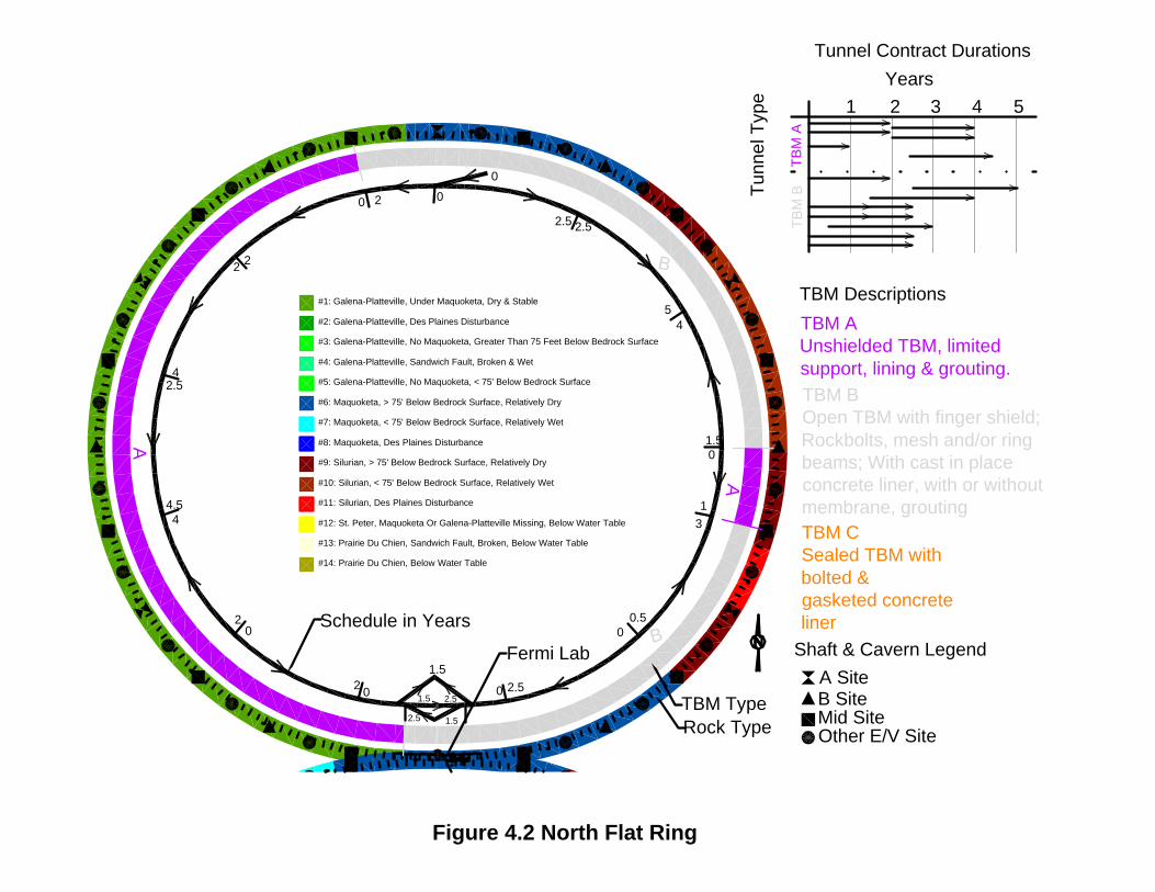
4 Heavy Civil Underground Construction Schedule The construction schedules include time for excavation and support of tunnels and shafts only. They were developed assuming that the construction could start at multiple locations on the tunnel ring, with early construction required at FermiLab and the opposite side to allow for installation of the experiment components. Work would start with the construction of the shafts required for tunneling access. After these were complete, only the TBM tunneling was assumed to be on the critical path because construction of other components could be concurrent and completed more quickly.
HMM maintains an automated system for estimating TBM tunnel costs and advance rates based on experience from previous projects. After the assumed ground conditions were determined, HMM used this system to calculate costs and advance rates using data from projects of similar TBM diameter and ground conditions. TBM Type A tunneling requires the least time and Type C requires the most. Based on the TBM progress rates in the costs analyses, it was determined tunneling for each TBM Type would take approximately the following amount of time: 1. Type A Tunneling—0.5 years for each 4844m drive. 2. Type B Tunneling—0.5 years for each 4844 drive plus a 0.5-year lag to allow the TBM to
complete a drive before starting the installation of concrete lining. 3. Type C Tunneling—1 year for each 4844m drive. Based on these the durations, each alignment option was broken down into separate construction contracts, as shown on the inner rings in Figures 4.1, 4.2, and 4.3. The charts in the upper right corner of each figure show tunnel contract durations. The construction time can also be summarized as follows:
Item North Inclined Ring
North Flat Ring South Inclined Ring
Total Project Duration (years) 4.5 5 5 Maximum No. of Concurrent Contracts 8 9 9 No. of Type A Tunnel Contracts 12 7 5 No. of Type B Tunnel Contracts 4 7 9 No. of Type C Tunnel Contracts 0 0 2
Table 6—Summary of Underground Construction Durations.
These durations are the minimum times required to complete the project. This timeline will need to be increased based on contractor availability, project funding profile, and the owner’s ability to manage the project.

VLHC Study 21
Bibliography Abert, Curtis C., 1996, Shaded Relief Map of Illinois, Illinois State Geological Survey, Map 6. Bauer, R.A., 1991, Geotechnical Properties if Selected Pleistocene, Silurian, and Ordovician Deposits of Northeastern Illinois: Environmental Geology 139. Bauer, Robert A., 1996, Summary of Mined Caverns in Illinois, Illinois State Geological Survey. Buschbach, T.C., 1972, Preliminary Geologic Investigations of Rock Tunnel Sites For Flood and Pollution Control in the Great Chicago Area: Illinois Geological Survey Bulletin 52, pp 9-13, 24-28. CNA Consulting Engineers, Cost estimating spreadsheet, Microsoft Excel, “vlhc_Underground_Construction.xls,” Provided to FermiLab, June, 2001. Conroy, Peter J., 2000, Characterization of Fermi Region Geology: presented at Second Annual VLHC Meeting, Port Jefferson, Long Island, NY. Curry, B.B. et al, 1988, Geological-Geotechnical Studies for Siting the Superconducting Super Collider in Illinois: Results of the 1986 Test Drilling Program, Illinois State Geological Survey, Environmental Geology Notes 122. "Design Study for a Staged Very Large Hadron Collider", Fermilab TM-2149 (2001). Sections can be viewed/downloaded from http://vlhc.org Ekblaw, George E., 1938, Kankakee Arch in Illinois, Reprinted from the Bulletin, Geological Society of America, Vol. 49, pp. 1425 – 1430, 1938. Fluor Daniel/Harza, 1998, NuMI Project Geotechnical Data Report, Fermi National Accelerator Laboratory, Batavia, Illinois. Harza Engineering Company, 2000, Next Linear Collider (NLC) Project, North—South Alignment Geotechnical Study: Fermi National Accelerator Laboratory. Harza Engineering Company, State of Illinois, Department of Energy and Natural Resources, SSC Permitting Report. Herzog, B.L., 1994, Buried Bedrock Surface of Illinois: Illinois State Geological Survey Illinois Map 5. Kempton, J.P. et al, 1985, Geological-Geotechnical Studies for Siting the Superconducting Super Collider in Illinois: Preliminary Geological Feasibility Report, State Geological Survey, Environmental Geology Notes 111. Kempton, J.P. et al, 1987, Geological-Geotechnical Studies for Siting the Superconducting Super Collider in Illinois, Results of the Fall 1984 Test Drilling Program, State Geological Survey Division, Environmental Geology Notes 117. Kempton, J.P., 1987, Geological—Geotechnical Studies for Siting the Superconducting Super Collider in Illinois: Environmental Geology Notes 120.

VLHC Study 22
Kolata, D.R., 1978, The Sandwich Fault Zone of Northern Illinois: Illinois State Geological Survey Circular 505, pp 10-17. Nelson, W. John, 1995, Structural Features in Illinois: Illinois State Geological Survey, Bulletin 100. Shaw, Thomas H. and Sargent, Michael L., 1989, Catalog of cores from the sub-Galena Group in Illinois, Illinois State Geological Survey, Illinois Petroleum 132. STS Consultants Limited, 1997, Hydrogeological Evaluation Report Fermi National Accelerator Laboratory Neutrino Main Injector (NuMI), Batavia, Illinois, Volume I of II. STS Consultants Limited, 1997, Hydrogeological Evaluation Report Fermi National Accelerator Laboratory Neutrino Main Injector (NuMI), Batavia, Illinois, Volume II of II. STS Consultants Limited, 1993, Subsurface Exploration and Geotechnical Data Report for the NUMI Project, Fermi National Accelerator Laboratory Report. Turner Construction Company, Turner Building Cost Index, http://www.turnerconstruction.com/cost.html Visocky, A.P., 1985, Geology, Hydrology, and Water Quality of the Cambrian and Ordovician Systems in Northern Illinois: Cooperative Groundwater Report 10. Visocky, Adrian P., 1997, Water-Level Trends and Pumpage in the Deep Bedrock Aquifers in the Chicago Region, 1991-1995, Illinois State Water Survey. Willman, H. B., 1971, Summary of the Geology of the Chicago Area, Illinois State Geological Survey, Circular 460.

Figures


#1: Galena-Platteville, Under Maquoketa, Dry & Stable
#8: Maquoketa, Des Plaines Disturbance
#2: Galena-Platteville, Des Plaines Disturbance
#3: Galena-Platteville, No Maquoketa, Greater Than 75 Feet Below Bedrock Surface
#4: Galena-Platteville, Sandwich Fault, Broken & Wet
#5: Galena-Platteville, No Maquoketa, < 75' Below Bedrock Surface
#6: Maquoketa, > 75' Below Bedrock Surface, Relatively Dry
#7: Maquoketa, < 75' Below Bedrock Surface, Relatively Wet
#9: Silurian, > 75' Below Bedrock Surface, Relatively Dry
#10: Silurian, < 75' Below Bedrock Surface, Relatively Wet
#11: Silurian, Des Plaines Disturbance
#12: St. Peter, Maquoketa Or Galena-Platteville Missing, Below Water Table
#14: Prairie Du Chien, Below Water Table
A SiteB SiteMid SiteOther E/V Site
#13: Prairie Du Chien, Sandwich Fault, Broken, Below Water Table
Rock Type
Shaft & Cavern Legend
Fermi Lab
Figure 2.1 North Inclined Ring

Figure 2.2 - Fermi VLHC -- North Inclined Ring
-200
0
200
400
600
800
1000
0000+00. 0250+00. 0500+00. 0750+00. 1000+00. 1250+00. 1500+00. 1750+00. 2000+00. 2250+00.
Station Clockwise from Fermi Lab(meters)
Ele
vati
on
(ft
)
Surface Inclined Ring Base Soil / Top Silurian Base Silurian / Top Maquoketa Base Maquoketa / Top G-P
Base G-P / Top Ancell Groundwater Base Ancell / Top PdC Shafts
T. 1
T. x = rock type. See report section 2.3
T. 2 T. 1
Fermi Lab

#1: Galena-Platteville, Under Maquoketa, Dry & Stable
#8: Maquoketa, Des Plaines Disturbance
#2: Galena-Platteville, Des Plaines Disturbance
#3: Galena-Platteville, No Maquoketa, Greater Than 75 Feet Below Bedrock Surface
#4: Galena-Platteville, Sandwich Fault, Broken & Wet
#5: Galena-Platteville, No Maquoketa, < 75' Below Bedrock Surface
#6: Maquoketa, > 75' Below Bedrock Surface, Relatively Dry
#7: Maquoketa, < 75' Below Bedrock Surface, Relatively Wet
#9: Silurian, > 75' Below Bedrock Surface, Relatively Dry
#10: Silurian, < 75' Below Bedrock Surface, Relatively Wet
#11: Silurian, Des Plaines Disturbance
#12: St. Peter, Maquoketa Or Galena-Platteville Missing, Below Water Table
#13: Prairie Du Chien, Sandwich Fault, Broken, Below Water Table
#14: Prairie Du Chien, Below Water Table
Rock Type
A SiteB SiteMid SiteOther E/V Site
Shaft & Cavern LegendFermi Lab
Figure 2.3 North Flat Ring

Figure 2.4 - Fermi VLHC -- North Flat Ring
-200
0
200
400
600
800
1000
0000+00. 0250+00. 0500+00. 0750+00. 1000+00. 1250+00. 1500+00. 1750+00. 2000+00. 2250+00.
Station Clockwise from Fermi Lab (meters)
Ele
vati
on
(ft
)
Surface Flat Ring Base Soil / Top Silurian Base Silurian / Top Maquoketa Base Maquoketa / Top G-P Base G-P / Top Ancell GW Elevation Base Ancell / Top PdC Shafts
T.6 T.1 T.9T.6 T.9T.10 T.11 T.6T.9
T.x = rock type. See report section 2.3
Fermi Lab
#1: Galena-Platteville, Under Maquoketa, Dry & Stable
#8: Maquoketa, Des Plaines Disturbance
#2: Galena-Platteville, Des Plaines Disturbance
#3: Galena-Platteville, No Maquoketa, Greater Than 75 Feet Below Bedrock Surface
#4: Galena-Platteville, Sandwich Fault, Broken & Wet
#5: Galena-Platteville, No Maquoketa, < 75' Below Bedrock Surface
#6: Maquoketa, > 75' Below Bedrock Surface, Relatively Dry
#7: Maquoketa, < 75' Below Bedrock Surface, Relatively Wet
#9: Silurian, > 75' Below Bedrock Surface, Relatively Dry
#10: Silurian, < 75' Below Bedrock Surface, Relatively Wet
#11: Silurian, Des Plaines Disturbance
#12: St. Peter, Maquoketa Or Galena-Platteville Missing, Below Water Table
#13: Prairie Du Chien, Sandwich Fault, Broken, Below Water Table
#14: Prairie Du Chien, Below Water Table
Rock Type
A SiteB SiteMid SiteOther E/V Site
Shaft & Cavern Legend
Fermi Lab
Figure 2.5 South Inclined Ring
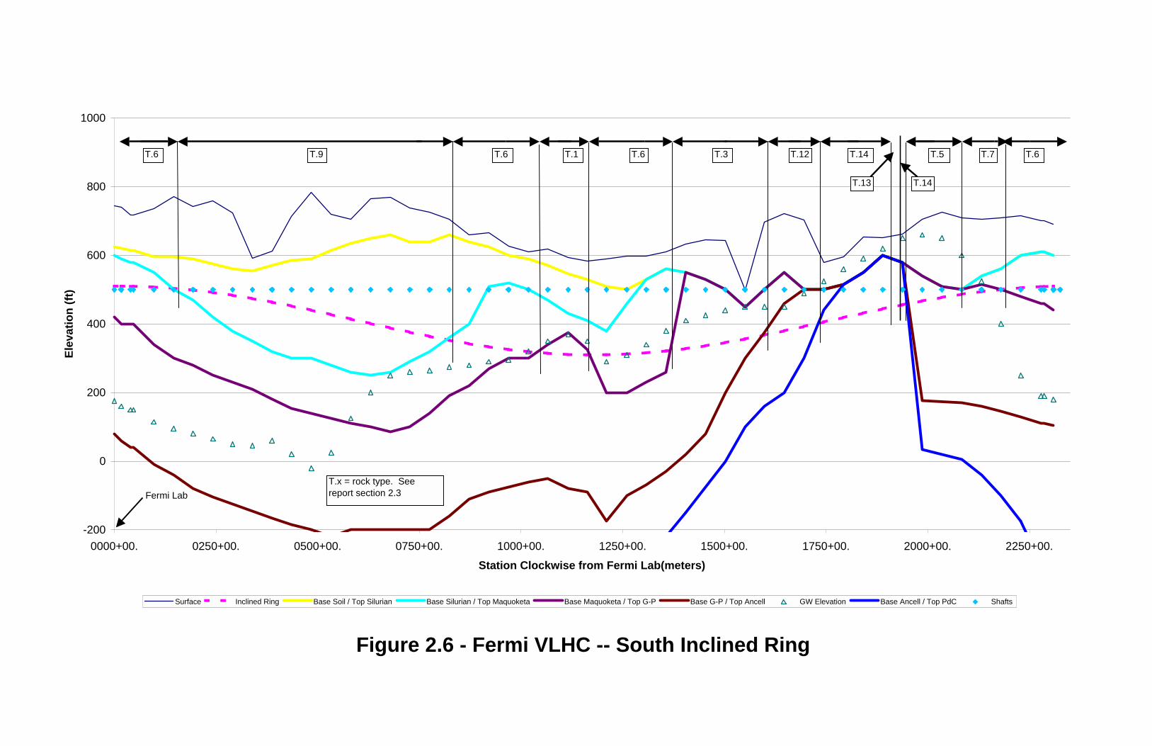
Figure 2.6 - Fermi VLHC -- South Inclined Ring
-200
0
200
400
600
800
1000
0000+00. 0250+00. 0500+00. 0750+00. 1000+00. 1250+00. 1500+00. 1750+00. 2000+00. 2250+00.
Station Clockwise from Fermi Lab(meters)
Ele
vati
on
(ft
)
Surface Inclined Ring Base Soil / Top Silurian Base Silurian / Top Maquoketa Base Maquoketa / Top G-P Base G-P / Top Ancell GW Elevation Base Ancell / Top PdC Shafts
T.6 T.1T.9 T.6 T.5T.3 T.12T.6
T.14T.13
T.7T.14 T.6
T.x = rock type. Seereport section 2.3Fermi Lab

Figure 3.1 - Rockbolt Spacing versus Q Rating
0
1
2
3
0.01 0.1 1 10 100
NGI "Q" Rating
Roc
kbol
t S
paci
ng (
m)
Empirical Values VLHC Caverns
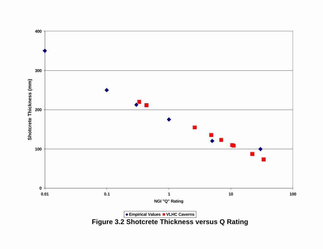
Figure 3.2 Shotcrete Thickness versus Q Rating
0
100
200
300
400
0.01 0.1 1 10 100
NGI "Q" Rating
Sh
otc
rete
Th
ickn
ess
(mm
)
Empirical Values VLHC Caverns

#1: Galena-Platteville, Under Maquoketa, Dry & Stable
#8: Maquoketa, Des Plaines Disturbance
#2: Galena-Platteville, Des Plaines Disturbance
#3: Galena-Platteville, No Maquoketa, Greater Than 75 Feet Below Bedrock Surface
#4: Galena-Platteville, Sandwich Fault, Broken & Wet
#5: Galena-Platteville, No Maquoketa, < 75' Below Bedrock Surface
#6: Maquoketa, > 75' Below Bedrock Surface, Relatively Dry
#7: Maquoketa, < 75' Below Bedrock Surface, Relatively Wet
#9: Silurian, > 75' Below Bedrock Surface, Relatively Dry
#10: Silurian, < 75' Below Bedrock Surface, Relatively Wet
#11: Silurian, Des Plaines Disturbance
#12: St. Peter, Maquoketa Or Galena-Platteville Missing, Below Water Table
#14: Prairie Du Chien, Below Water Table B
A
A SiteB SiteMid SiteOther E/V Site
TBM AUnshielded TBM, limited support, lining & grouting.
#13: Prairie Du Chien, Sandwich Fault, Broken, Below Water Table
TBM BOpen TBM with finger shield; Rockbolts, mesh and/or ring beams; With cast in place concrete liner, with or without membrane, groutingTBM CSealed TBM with bolted & gasketed concrete liner
Rock Type
TBM TypeShaft & Cavern Legend
Fermi Lab
Figure 3.3 North Inclined Ring

#1: Galena-Platteville, Under Maquoketa, Dry & Stable
#8: Maquoketa, Des Plaines Disturbance
#2: Galena-Platteville, Des Plaines Disturbance
#3: Galena-Platteville, No Maquoketa, Greater Than 75 Feet Below Bedrock Surface
#4: Galena-Platteville, Sandwich Fault, Broken & Wet
#5: Galena-Platteville, No Maquoketa, < 75' Below Bedrock Surface
#6: Maquoketa, > 75' Below Bedrock Surface, Relatively Dry
#7: Maquoketa, < 75' Below Bedrock Surface, Relatively Wet
#9: Silurian, > 75' Below Bedrock Surface, Relatively Dry
#10: Silurian, < 75' Below Bedrock Surface, Relatively Wet
#11: Silurian, Des Plaines Disturbance
#12: St. Peter, Maquoketa Or Galena-Platteville Missing, Below Water Table
#13: Prairie Du Chien, Sandwich Fault, Broken, Below Water Table
#14: Prairie Du Chien, Below Water Table
B
A
B
A
Rock TypeTBM Type
A SiteB SiteMid SiteOther E/V Site
TBM AUnshielded TBM, limited support, lining & grouting.TBM BOpen TBM with finger shield; Rockbolts, mesh and/or ring beams; With cast in place concrete liner, with or without membrane, groutingTBM CSealed TBM with bolted & gasketed concrete liner
Shaft & Cavern LegendFermi Lab
Figure 3.4 North Flat Ring

A
B
AB
A
C
A
#1: Galena-Platteville, Under Maquoketa, Dry & Stable
#8: Maquoketa, Des Plaines Disturbance
#2: Galena-Platteville, Des Plaines Disturbance
#3: Galena-Platteville, No Maquoketa, Greater Than 75 Feet Below Bedrock Surface
#4: Galena-Platteville, Sandwich Fault, Broken & Wet
#5: Galena-Platteville, No Maquoketa, < 75' Below Bedrock Surface
#6: Maquoketa, > 75' Below Bedrock Surface, Relatively Dry
#7: Maquoketa, < 75' Below Bedrock Surface, Relatively Wet
#9: Silurian, > 75' Below Bedrock Surface, Relatively Dry
#10: Silurian, < 75' Below Bedrock Surface, Relatively Wet
#11: Silurian, Des Plaines Disturbance
#12: St. Peter, Maquoketa Or Galena-Platteville Missing, Below Water Table
#13: Prairie Du Chien, Sandwich Fault, Broken, Below Water Table
#14: Prairie Du Chien, Below Water Table
Rock Type
TBM Type
A SiteB SiteMid SiteOther E/V Site
TBM AUnshielded TBM, limited support, lining & grouting.TBM BOpen TBM with finger shield; Rockbolts, mesh and/or ring beams; With cast in place concrete liner, with or without membrane, groutingTBM CSealed TBM with bolted & gasketed concrete liner
Shaft & Cavern Legend
Fermi Lab
B
Figure 3.5 South Inclined Ring

Figure 3.6 - Turner Building Cost Index
0
100
200
300
400
500
600
700
800
900
1967
1968
1969
1970
1971
1972
1973
1974
1975
1976
1977
1978
1979
1980
1981
1982
1983
1984
1985
1986
1987
1988
1989
1990
1991
1992
1993
1994
1995
1996
1997
1998
1999
2000
Tu
rner
Bu
ildin
g C
ost
Ind
ex
0
2
4
6
8
10
12
14
16
18
An
nu
al P
erce
nt
Ch
ang
e
% ChangeIndex

Figure 3.7 - Cost Breakdown
$0
$500
$1,000
$1,500
$2,000
$2,500
12' Diam.Tunnel
16' Diam.Tunnel
12' Diam.Tunnel
16' Diam.Tunnel
12' Diam.Tunnel
16' Diam.Tunnel
North Ring Inclined North Ring Flat South Ring Inclined
Co
st (
$1M
)
MiscPortalsRisersDB TunnelTBM TunnelsCavernsShafts

#1: Galena-Platteville, Under Maquoketa, Dry & Stable
#8: Maquoketa, Des Plaines Disturbance
#2: Galena-Platteville, Des Plaines Disturbance
#3: Galena-Platteville, No Maquoketa, Greater Than 75 Feet Below Bedrock Surface
#4: Galena-Platteville, Sandwich Fault, Broken & Wet
#5: Galena-Platteville, No Maquoketa, < 75' Below Bedrock Surface
#6: Maquoketa, > 75' Below Bedrock Surface, Relatively Dry
#7: Maquoketa, < 75' Below Bedrock Surface, Relatively Wet
#9: Silurian, > 75' Below Bedrock Surface, Relatively Dry
#10: Silurian, < 75' Below Bedrock Surface, Relatively Wet
#11: Silurian, Des Plaines Disturbance
#12: St. Peter, Maquoketa Or Galena-Platteville Missing, Below Water Table
#14: Prairie Du Chien, Below Water Table B
A
A SiteB SiteMid SiteOther E/V Site
TBM AUnshielded TBM, limited support, lining & grouting.
0
2 2
4.54
1.51.5
01.5
30
1.50
0 2
22
2.54
44.5
20
2 0
0
1.5
2.5 1.5
1.5 2.5
#13: Prairie Du Chien, Sandwich Fault, Broken, Below Water Table
Tun
nel T
ype
TB
M B
TB
M A
1 2 3 4 5
TBM BOpen TBM with finger shield; Rockbolts, mesh and/or ring beams; With cast in place concrete liner, with or without membrane, groutingTBM CSealed TBM with bolted & gasketed concrete liner
Schedule in Years
Rock Type
TBM Type
Tunnel Contract Durations
TBM Descriptions
Years
Shaft & Cavern Legend
Fermi Lab
Figure 4.1 North Inclined Ring
#1: Galena-Platteville, Under Maquoketa, Dry & Stable
#8: Maquoketa, Des Plaines Disturbance
#2: Galena-Platteville, Des Plaines Disturbance
#3: Galena-Platteville, No Maquoketa, Greater Than 75 Feet Below Bedrock Surface
#4: Galena-Platteville, Sandwich Fault, Broken & Wet
#5: Galena-Platteville, No Maquoketa, < 75' Below Bedrock Surface
#6: Maquoketa, > 75' Below Bedrock Surface, Relatively Dry
#7: Maquoketa, < 75' Below Bedrock Surface, Relatively Wet
#9: Silurian, > 75' Below Bedrock Surface, Relatively Dry
#10: Silurian, < 75' Below Bedrock Surface, Relatively Wet
#11: Silurian, Des Plaines Disturbance
#12: St. Peter, Maquoketa Or Galena-Platteville Missing, Below Water Table
#13: Prairie Du Chien, Sandwich Fault, Broken, Below Water Table
#14: Prairie Du Chien, Below Water Table
B
A
B
A
0
2.5
1.50
13
0.50
2.50
0 2
22
2.54
44.5
20
2 0
0
1.5
2.5 1.5
1.5 2.5
2.5
54
Rock TypeTBM Type
Schedule in Years
A SiteB SiteMid SiteOther E/V Site
TBM AUnshielded TBM, limited support, lining & grouting.TBM BOpen TBM with finger shield; Rockbolts, mesh and/or ring beams; With cast in place concrete liner, with or without membrane, groutingTBM CSealed TBM with bolted & gasketed concrete liner
TBM Descriptions
Shaft & Cavern Legend
1 2 3 4 5
Tunnel Contract Durations
Years
Tun
nel T
ype
TB
M B
TB
M A
Fermi Lab
Figure 4.2 North Flat Ring

A
B
AB
A
C
A
#1: Galena-Platteville, Under Maquoketa, Dry & Stable
#8: Maquoketa, Des Plaines Disturbance
#2: Galena-Platteville, Des Plaines Disturbance
#3: Galena-Platteville, No Maquoketa, Greater Than 75 Feet Below Bedrock Surface
#4: Galena-Platteville, Sandwich Fault, Broken & Wet
#5: Galena-Platteville, No Maquoketa, < 75' Below Bedrock Surface
#6: Maquoketa, > 75' Below Bedrock Surface, Relatively Dry
#7: Maquoketa, < 75' Below Bedrock Surface, Relatively Wet
#9: Silurian, > 75' Below Bedrock Surface, Relatively Dry
#10: Silurian, < 75' Below Bedrock Surface, Relatively Wet
#11: Silurian, Des Plaines Disturbance
#12: St. Peter, Maquoketa Or Galena-Platteville Missing, Below Water Table
#13: Prairie Du Chien, Sandwich Fault, Broken, Below Water Table
#14: Prairie Du Chien, Below Water Table
0
54
2.52
4.50
20
2.52.5
50
34
3.50
20
0
1.5
2.5 1.5
1.5 2.5
33
2 0
02
Rock Type
TBM Type
Schedule in Years
A SiteB SiteMid SiteOther E/V Site
TBM AUnshielded TBM, limited support, lining & grouting.TBM BOpen TBM with finger shield; Rockbolts, mesh and/or ring beams; With cast in place concrete liner, with or without membrane, groutingTBM CSealed TBM with bolted & gasketed concrete liner
TBM Descriptions
Shaft & Cavern LegendT
unne
l Typ
e
TB
M B
TB
M A
1 2 3 4 5
Tunnel Contract DurationsYears
TB
M C
Fermi Lab
B
Figure 4.3 South Inclined Ring

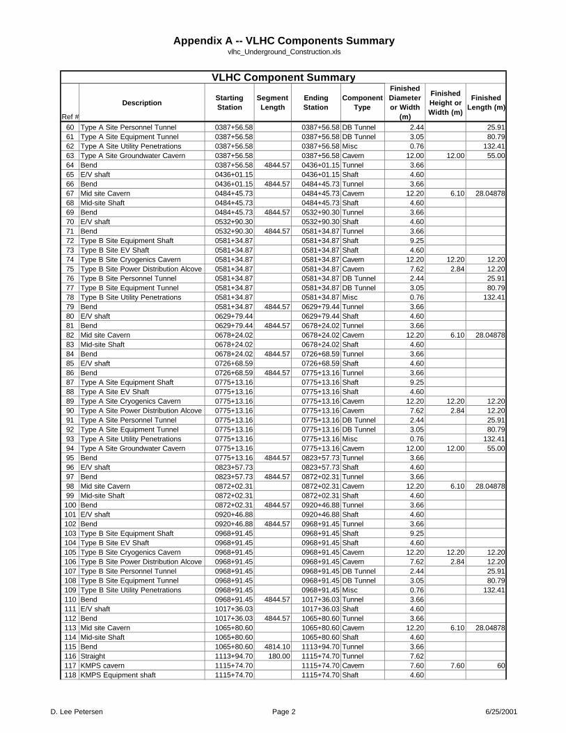
Appendix A—Listing of Project Components

Appendix A -- VLHC Components Summaryvlhc_Underground_Construction.xls
Ref #
DescriptionStarting Station
Segment Length
Ending Station
Component Type
Finished Diameter or Width
(m)
Finished Height or Width (m)
Finished Length (m)
1 Type A Site Equipment Shaft 0000+00.00 0000+00.00 Shaft 9.252 Type A Site EV Shaft 0000+00.00 0000+00.00 Shaft 4.603 Type A Site Cryogenics Cavern 0000+00.00 0000+00.00 Cavern 12.20 12.20 12.204 Type A Site Power Distribution Alcove 0000+00.00 0000+00.00 Cavern 7.62 2.84 12.205 Type A Site Personnel Tunnel 0000+00.00 0000+00.00 DB Tunnel 2.44 25.916 Type A Site Equipment Tunnel 0000+00.00 0000+00.00 DB Tunnel 3.05 80.797 Type A Site Utility Penetrations 0000+00.00 0000+00.00 Misc 0.76 132.418 Type A Site Groundwater Cavern 0000+00.00 0000+00.00 Cavern 12.00 12.00 55.009 Straight 0000+00.00 137.00 0001+37.00 Tunnel 3.66
10 Bend 0001+37.00 723.38 0008+60.38 Tunnel 3.6611 Straight 0008+60.38 820.00 0016+80.38 Tunnel 3.6612 Experimental Cavern 0016+80.38 0016+80.38 Cavern 30.00 45.00 10013 E.C. Cable Electronics Shaft 0016+80.38 0016+80.38 Shaft 13.00 18.0014 E.C. Utility Shaft 0016+80.38 0016+80.38 Shaft 13.00 17.5015 E.C. Installation Shaft 0016+80.38 0016+80.38 Shaft 18.00 28.0016 E.C. Installation Shaft 0016+80.38 0016+80.38 Shaft 18.00 25.0017 E.C. Connection Tunnels 0016+80.38 0016+80.38 DB Tunnel 13.00 9518 E.C. Utlity Bypass Tunnel 0016+80.38 0016+80.38 DB Tunnel 9.25 29419 Straight 0016+80.38 820.00 0025+00.38 Tunnel 3.6620 Bend 0025+00.38 994.67 0034+95.05 Tunnel 3.6621 Abort tunnel cavern 0034+95.05 0034+95.05 Cavern 7.85 5.00 65022 Straight 0034+95.05 410.00 0039+05.05 Tunnel 7.6223 RFKT cavern 0039+05.05 0039+05.05 Cavern 7.60 7.60 7524 RFKT Equipment shaft 0039+05.05 0039+05.05 Shaft 9.2525 RFKT Utility Penetrations 0039+05.05 0039+05.05 Misc 0.76 132.4126 RFKT Personnel Tunnel 0039+05.05 0039+05.05 DB Tunnel 2.44 25.9127 Straight 0039+05.05 130.00 0040+35.05 Tunnel 7.6228 Injection-Straight interface cavern 0040+35.05 0040+35.05 Cavern 7.62 7.62 10029 Straight 0040+35.05 660.00 0046+95.05 Tunnel 7.6230 KMPS cavern 0046+95.05 0046+95.05 Cavern 7.60 7.60 6031 KMPS Equipment shaft 0046+95.05 0046+95.05 Shaft 4.6032 KMPS utility penetrations 0046+95.05 0046+95.05 Misc 0.30 132.4133 KMPS personnel tunnel 0046+95.05 0046+95.05 DB Tunnel 3.66 21.3634 Straight 0046+95.05 180.00 0048+75.05 Tunnel 7.6235 Bend 0048+75.05 4814.10 0096+89.15 Tunnel 3.6636 Mid site Cavern 0096+89.15 0096+89.15 Cavern 12.20 6.10 28.0537 Mid-site Shaft 0096+89.15 0096+89.15 Shaft 4.6038 Bend 0096+89.15 4844.57 0145+33.72 Tunnel 3.6639 E/V shaft 0145+33.72 0145+33.72 Shaft 4.6040 Bend 0145+33.72 4844.57 0193+78.29 Tunnel 3.6641 Type B Site Equipment Shaft 0193+78.29 0193+78.29 Shaft 9.2542 Type B Site EV Shaft 0193+78.29 0193+78.29 Shaft 4.6043 Type B Site Cryogenics Cavern 0193+78.29 0193+78.29 Cavern 12.20 12.20 12.2044 Type B Site Power Distribution Alcove 0193+78.29 0193+78.29 Cavern 7.62 2.84 12.2045 Type B Site Personnel Tunnel 0193+78.29 0193+78.29 DB Tunnel 2.44 25.9146 Type B Site Equipment Tunnel 0193+78.29 0193+78.29 DB Tunnel 3.05 80.7947 Type B Site Utility Penetrations 0193+78.29 0193+78.29 Misc 0.76 132.4148 Bend 0193+78.29 4844.57 0242+22.86 Tunnel 3.6649 E/V shaft 0242+22.86 0242+22.86 Shaft 4.6050 Bend 0242+22.86 4844.57 0290+67.44 Tunnel 3.6651 Mid site Cavern 0290+67.44 0290+67.44 Cavern 12.20 6.10 28.0487852 Mid-site Shaft 0290+67.44 0290+67.44 Shaft 4.6053 Bend 0290+67.44 4844.57 0339+12.01 Tunnel 3.6654 E/V shaft 0339+12.01 0339+12.01 Shaft 4.6055 Bend 0339+12.01 4844.57 0387+56.58 Tunnel 3.6656 Type A Site Equipment Shaft 0387+56.58 0387+56.58 Shaft 9.2557 Type A Site EV Shaft 0387+56.58 0387+56.58 Shaft 4.6058 Type A Site Cryogenics Cavern 0387+56.58 0387+56.58 Cavern 12.20 12.20 12.2059 Type A Site Power Distribution Alcove 0387+56.58 0387+56.58 Cavern 7.62 2.84 12.20
VLHC Component Summary
D. Lee Petersen Page 1 6/25/2001
Appendix A -- VLHC Components Summaryvlhc_Underground_Construction.xls
Ref #
DescriptionStarting Station
Segment Length
Ending Station
Component Type
Finished Diameter or Width
(m)
Finished Height or Width (m)
Finished Length (m)
VLHC Component Summary
60 Type A Site Personnel Tunnel 0387+56.58 0387+56.58 DB Tunnel 2.44 25.9161 Type A Site Equipment Tunnel 0387+56.58 0387+56.58 DB Tunnel 3.05 80.7962 Type A Site Utility Penetrations 0387+56.58 0387+56.58 Misc 0.76 132.4163 Type A Site Groundwater Cavern 0387+56.58 0387+56.58 Cavern 12.00 12.00 55.0064 Bend 0387+56.58 4844.57 0436+01.15 Tunnel 3.6665 E/V shaft 0436+01.15 0436+01.15 Shaft 4.6066 Bend 0436+01.15 4844.57 0484+45.73 Tunnel 3.6667 Mid site Cavern 0484+45.73 0484+45.73 Cavern 12.20 6.10 28.0487868 Mid-site Shaft 0484+45.73 0484+45.73 Shaft 4.6069 Bend 0484+45.73 4844.57 0532+90.30 Tunnel 3.6670 E/V shaft 0532+90.30 0532+90.30 Shaft 4.6071 Bend 0532+90.30 4844.57 0581+34.87 Tunnel 3.6672 Type B Site Equipment Shaft 0581+34.87 0581+34.87 Shaft 9.2573 Type B Site EV Shaft 0581+34.87 0581+34.87 Shaft 4.6074 Type B Site Cryogenics Cavern 0581+34.87 0581+34.87 Cavern 12.20 12.20 12.2075 Type B Site Power Distribution Alcove 0581+34.87 0581+34.87 Cavern 7.62 2.84 12.2076 Type B Site Personnel Tunnel 0581+34.87 0581+34.87 DB Tunnel 2.44 25.9177 Type B Site Equipment Tunnel 0581+34.87 0581+34.87 DB Tunnel 3.05 80.7978 Type B Site Utility Penetrations 0581+34.87 0581+34.87 Misc 0.76 132.4179 Bend 0581+34.87 4844.57 0629+79.44 Tunnel 3.6680 E/V shaft 0629+79.44 0629+79.44 Shaft 4.6081 Bend 0629+79.44 4844.57 0678+24.02 Tunnel 3.6682 Mid site Cavern 0678+24.02 0678+24.02 Cavern 12.20 6.10 28.0487883 Mid-site Shaft 0678+24.02 0678+24.02 Shaft 4.6084 Bend 0678+24.02 4844.57 0726+68.59 Tunnel 3.6685 E/V shaft 0726+68.59 0726+68.59 Shaft 4.6086 Bend 0726+68.59 4844.57 0775+13.16 Tunnel 3.6687 Type A Site Equipment Shaft 0775+13.16 0775+13.16 Shaft 9.2588 Type A Site EV Shaft 0775+13.16 0775+13.16 Shaft 4.6089 Type A Site Cryogenics Cavern 0775+13.16 0775+13.16 Cavern 12.20 12.20 12.2090 Type A Site Power Distribution Alcove 0775+13.16 0775+13.16 Cavern 7.62 2.84 12.2091 Type A Site Personnel Tunnel 0775+13.16 0775+13.16 DB Tunnel 2.44 25.9192 Type A Site Equipment Tunnel 0775+13.16 0775+13.16 DB Tunnel 3.05 80.7993 Type A Site Utility Penetrations 0775+13.16 0775+13.16 Misc 0.76 132.4194 Type A Site Groundwater Cavern 0775+13.16 0775+13.16 Cavern 12.00 12.00 55.0095 Bend 0775+13.16 4844.57 0823+57.73 Tunnel 3.6696 E/V shaft 0823+57.73 0823+57.73 Shaft 4.6097 Bend 0823+57.73 4844.57 0872+02.31 Tunnel 3.6698 Mid site Cavern 0872+02.31 0872+02.31 Cavern 12.20 6.10 28.0487899 Mid-site Shaft 0872+02.31 0872+02.31 Shaft 4.60100 Bend 0872+02.31 4844.57 0920+46.88 Tunnel 3.66101 E/V shaft 0920+46.88 0920+46.88 Shaft 4.60102 Bend 0920+46.88 4844.57 0968+91.45 Tunnel 3.66103 Type B Site Equipment Shaft 0968+91.45 0968+91.45 Shaft 9.25104 Type B Site EV Shaft 0968+91.45 0968+91.45 Shaft 4.60105 Type B Site Cryogenics Cavern 0968+91.45 0968+91.45 Cavern 12.20 12.20 12.20106 Type B Site Power Distribution Alcove 0968+91.45 0968+91.45 Cavern 7.62 2.84 12.20107 Type B Site Personnel Tunnel 0968+91.45 0968+91.45 DB Tunnel 2.44 25.91108 Type B Site Equipment Tunnel 0968+91.45 0968+91.45 DB Tunnel 3.05 80.79109 Type B Site Utility Penetrations 0968+91.45 0968+91.45 Misc 0.76 132.41110 Bend 0968+91.45 4844.57 1017+36.03 Tunnel 3.66111 E/V shaft 1017+36.03 1017+36.03 Shaft 4.60112 Bend 1017+36.03 4844.57 1065+80.60 Tunnel 3.66113 Mid site Cavern 1065+80.60 1065+80.60 Cavern 12.20 6.10 28.04878114 Mid-site Shaft 1065+80.60 1065+80.60 Shaft 4.60115 Bend 1065+80.60 4814.10 1113+94.70 Tunnel 3.66116 Straight 1113+94.70 180.00 1115+74.70 Tunnel 7.62117 KMPS cavern 1115+74.70 1115+74.70 Cavern 7.60 7.60 60118 KMPS Equipment shaft 1115+74.70 1115+74.70 Shaft 4.60
D. Lee Petersen Page 2 6/25/2001

Appendix A -- VLHC Components Summaryvlhc_Underground_Construction.xls
Ref #
DescriptionStarting Station
Segment Length
Ending Station
Component Type
Finished Diameter or Width
(m)
Finished Height or Width (m)
Finished Length (m)
VLHC Component Summary
119 KMPS utility penetrations 1115+74.70 1115+74.70 Misc 0.30 132.41120 KMPS personnel tunnel 1115+74.70 1115+74.70 DB Tunnel 3.66 21.36121 Straight 1115+74.70 660.00 1122+34.70 Tunnel 7.62122 Injection-Straight interface cavern 1122+34.70 1122+34.70 Cavern 7.62 7.62 100123 Straight 1122+34.70 130.00 1123+64.70 Tunnel 7.62124 Straight 1123+64.70 410.00 1127+74.70 Tunnel 7.62125 Bend 1127+74.70 994.67 1137+69.36 Tunnel 3.66126 Straight 1137+69.36 820.00 1145+89.36 Tunnel 3.66127 Straight 1145+89.36 820.00 1154+09.36 Tunnel 3.66128 Bend 1154+09.36 723.38 1161+32.74 Tunnel 3.66129 Straight 1161+32.74 137.00 1162+69.74 Tunnel 3.66130 Type A Site Equipment Shaft 1162+69.74 1162+69.74 Shaft 9.25131 Type A Site EV Shaft 1162+69.74 1162+69.74 Shaft 4.60132 Type A Site Cryogenics Cavern 1162+69.74 1162+69.74 Cavern 12.20 12.20 12.20133 Type A Site Power Distribution Alcove 1162+69.74 1162+69.74 Cavern 7.62 2.84 12.20134 Type A Site Personnel Tunnel 1162+69.74 1162+69.74 DB Tunnel 2.44 25.91135 Type A Site Equipment Tunnel 1162+69.74 1162+69.74 DB Tunnel 3.05 80.79136 Type A Site Utility Penetrations 1162+69.74 1162+69.74 Misc 0.76 132.41137 Type A Site Groundwater Cavern 1162+69.74 1162+69.74 Cavern 12.00 12.00 55.00138 Straight 1162+69.74 137.00 1164+06.74 Tunnel 3.66139 Bend 1164+06.74 723.38 1171+30.12 Tunnel 3.66140 Straight 1171+30.12 820.00 1179+50.12 Tunnel 3.66141 Straight 1179+50.12 820.00 1187+70.12 Tunnel 3.66142 Bend 1187+70.12 994.67 1197+64.79 Tunnel 3.66143 Straight 1197+64.79 410.00 1201+74.79 Tunnel 7.62144 Straight 1201+74.79 130.00 1203+04.79 Tunnel 7.62145 Straight 1203+04.79 660.00 1209+64.79 Tunnel 7.62146 KMPS cavern 1209+64.79 1209+64.79 Cavern 7.60 7.60 60147 KMPS Equipment shaft 1209+64.79 1209+64.79 Shaft 4.60148 KMPS utility penetrations 1209+64.79 1209+64.79 Misc 0.30 132.41149 KMPS personnel tunnel 1209+64.79 1209+64.79 DB Tunnel 3.66 21.36150 Straight 1209+64.79 180.00 1211+44.79 Tunnel 3.66151 Bend 1211+44.79 4814.10 1259+58.89 Tunnel 3.66152 Mid site Cavern 1259+58.89 1259+58.89 Cavern 12.20 6.10 28.04878153 Mid-site Shaft 1259+58.89 1259+58.89 Shaft 4.60154 Bend 1259+58.89 4844.57 1308+03.46 Tunnel 3.66155 E/V shaft 1308+03.46 1308+03.46 Shaft 4.60156 Bend 1308+03.46 4844.57 1356+48.03 Tunnel 3.66157 Type B Site Equipment Shaft 1356+48.03 1356+48.03 Shaft 9.25158 Type B Site EV Shaft 1356+48.03 1356+48.03 Shaft 4.60159 Type B Site Cryogenics Cavern 1356+48.03 1356+48.03 Cavern 12.20 12.20 12.20160 Type B Site Power Distribution Alcove 1356+48.03 1356+48.03 Cavern 7.62 2.84 12.20161 Type B Site Personnel Tunnel 1356+48.03 1356+48.03 DB Tunnel 2.44 25.91162 Type B Site Equipment Tunnel 1356+48.03 1356+48.03 DB Tunnel 3.05 80.79163 Type B Site Utility Penetrations 1356+48.03 1356+48.03 Misc 0.76 132.41164 Bend 1356+48.03 4844.57 1404+92.61 Tunnel 3.66165 E/V shaft 1404+92.61 1404+92.61 Shaft 4.60166 Bend 1404+92.61 4844.57 1453+37.18 Tunnel 3.66167 Mid site Cavern 1453+37.18 1453+37.18 Cavern 12.20 6.10 28.04878168 Mid-site Shaft 1453+37.18 1453+37.18 Shaft 4.60169 Bend 1453+37.18 4844.57 1501+81.75 Tunnel 3.66170 E/V shaft 1501+81.75 1501+81.75 Shaft 4.60171 Bend 1501+81.75 4844.57 1550+26.32 Tunnel 3.66172 Type A Site Equipment Shaft 1550+26.32 1550+26.32 Shaft 9.25173 Type A Site EV Shaft 1550+26.32 1550+26.32 Shaft 4.60174 Type A Site Cryogenics Cavern 1550+26.32 1550+26.32 Cavern 12.20 12.20 12.20175 Type A Site Power Distribution Alcove 1550+26.32 1550+26.32 Cavern 7.62 2.84 12.20176 Type A Site Personnel Tunnel 1550+26.32 1550+26.32 DB Tunnel 2.44 25.91177 Type A Site Equipment Tunnel 1550+26.32 1550+26.32 DB Tunnel 3.05 80.79
D. Lee Petersen Page 3 6/25/2001
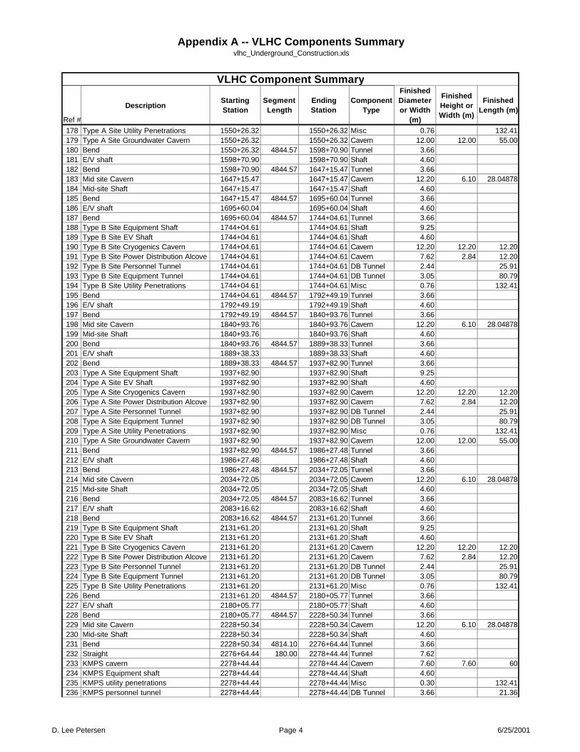
Appendix A -- VLHC Components Summaryvlhc_Underground_Construction.xls
Ref #
DescriptionStarting Station
Segment Length
Ending Station
Component Type
Finished Diameter or Width
(m)
Finished Height or Width (m)
Finished Length (m)
VLHC Component Summary
178 Type A Site Utility Penetrations 1550+26.32 1550+26.32 Misc 0.76 132.41179 Type A Site Groundwater Cavern 1550+26.32 1550+26.32 Cavern 12.00 12.00 55.00180 Bend 1550+26.32 4844.57 1598+70.90 Tunnel 3.66181 E/V shaft 1598+70.90 1598+70.90 Shaft 4.60182 Bend 1598+70.90 4844.57 1647+15.47 Tunnel 3.66183 Mid site Cavern 1647+15.47 1647+15.47 Cavern 12.20 6.10 28.04878184 Mid-site Shaft 1647+15.47 1647+15.47 Shaft 4.60185 Bend 1647+15.47 4844.57 1695+60.04 Tunnel 3.66186 E/V shaft 1695+60.04 1695+60.04 Shaft 4.60187 Bend 1695+60.04 4844.57 1744+04.61 Tunnel 3.66188 Type B Site Equipment Shaft 1744+04.61 1744+04.61 Shaft 9.25189 Type B Site EV Shaft 1744+04.61 1744+04.61 Shaft 4.60190 Type B Site Cryogenics Cavern 1744+04.61 1744+04.61 Cavern 12.20 12.20 12.20191 Type B Site Power Distribution Alcove 1744+04.61 1744+04.61 Cavern 7.62 2.84 12.20192 Type B Site Personnel Tunnel 1744+04.61 1744+04.61 DB Tunnel 2.44 25.91193 Type B Site Equipment Tunnel 1744+04.61 1744+04.61 DB Tunnel 3.05 80.79194 Type B Site Utility Penetrations 1744+04.61 1744+04.61 Misc 0.76 132.41195 Bend 1744+04.61 4844.57 1792+49.19 Tunnel 3.66196 E/V shaft 1792+49.19 1792+49.19 Shaft 4.60197 Bend 1792+49.19 4844.57 1840+93.76 Tunnel 3.66198 Mid site Cavern 1840+93.76 1840+93.76 Cavern 12.20 6.10 28.04878199 Mid-site Shaft 1840+93.76 1840+93.76 Shaft 4.60200 Bend 1840+93.76 4844.57 1889+38.33 Tunnel 3.66201 E/V shaft 1889+38.33 1889+38.33 Shaft 4.60202 Bend 1889+38.33 4844.57 1937+82.90 Tunnel 3.66203 Type A Site Equipment Shaft 1937+82.90 1937+82.90 Shaft 9.25204 Type A Site EV Shaft 1937+82.90 1937+82.90 Shaft 4.60205 Type A Site Cryogenics Cavern 1937+82.90 1937+82.90 Cavern 12.20 12.20 12.20206 Type A Site Power Distribution Alcove 1937+82.90 1937+82.90 Cavern 7.62 2.84 12.20207 Type A Site Personnel Tunnel 1937+82.90 1937+82.90 DB Tunnel 2.44 25.91208 Type A Site Equipment Tunnel 1937+82.90 1937+82.90 DB Tunnel 3.05 80.79209 Type A Site Utility Penetrations 1937+82.90 1937+82.90 Misc 0.76 132.41210 Type A Site Groundwater Cavern 1937+82.90 1937+82.90 Cavern 12.00 12.00 55.00211 Bend 1937+82.90 4844.57 1986+27.48 Tunnel 3.66212 E/V shaft 1986+27.48 1986+27.48 Shaft 4.60213 Bend 1986+27.48 4844.57 2034+72.05 Tunnel 3.66214 Mid site Cavern 2034+72.05 2034+72.05 Cavern 12.20 6.10 28.04878215 Mid-site Shaft 2034+72.05 2034+72.05 Shaft 4.60216 Bend 2034+72.05 4844.57 2083+16.62 Tunnel 3.66217 E/V shaft 2083+16.62 2083+16.62 Shaft 4.60218 Bend 2083+16.62 4844.57 2131+61.20 Tunnel 3.66219 Type B Site Equipment Shaft 2131+61.20 2131+61.20 Shaft 9.25220 Type B Site EV Shaft 2131+61.20 2131+61.20 Shaft 4.60221 Type B Site Cryogenics Cavern 2131+61.20 2131+61.20 Cavern 12.20 12.20 12.20222 Type B Site Power Distribution Alcove 2131+61.20 2131+61.20 Cavern 7.62 2.84 12.20223 Type B Site Personnel Tunnel 2131+61.20 2131+61.20 DB Tunnel 2.44 25.91224 Type B Site Equipment Tunnel 2131+61.20 2131+61.20 DB Tunnel 3.05 80.79225 Type B Site Utility Penetrations 2131+61.20 2131+61.20 Misc 0.76 132.41226 Bend 2131+61.20 4844.57 2180+05.77 Tunnel 3.66227 E/V shaft 2180+05.77 2180+05.77 Shaft 4.60228 Bend 2180+05.77 4844.57 2228+50.34 Tunnel 3.66229 Mid site Cavern 2228+50.34 2228+50.34 Cavern 12.20 6.10 28.04878230 Mid-site Shaft 2228+50.34 2228+50.34 Shaft 4.60231 Bend 2228+50.34 4814.10 2276+64.44 Tunnel 3.66232 Straight 2276+64.44 180.00 2278+44.44 Tunnel 7.62233 KMPS cavern 2278+44.44 2278+44.44 Cavern 7.60 7.60 60234 KMPS Equipment shaft 2278+44.44 2278+44.44 Shaft 4.60235 KMPS utility penetrations 2278+44.44 2278+44.44 Misc 0.30 132.41236 KMPS personnel tunnel 2278+44.44 2278+44.44 DB Tunnel 3.66 21.36
D. Lee Petersen Page 4 6/25/2001

Appendix A -- VLHC Components Summaryvlhc_Underground_Construction.xls
Ref #
DescriptionStarting Station
Segment Length
Ending Station
Component Type
Finished Diameter or Width
(m)
Finished Height or Width (m)
Finished Length (m)
VLHC Component Summary
237 Straight 2278+44.44 660.00 2285+04.44 Tunnel 7.62238 Injection-Straight interface cavern 2285+04.44 2285+04.44 Cavern 7.62 7.62 100.00239 Straight 2285+04.44 130.00 2286+34.44 Tunnel 7.62240 RFKT cavern 2286+34.44 2286+34.44 Cavern 7.60 7.60 75.00241 RFKT Equipment shaft 2286+34.44 2286+34.44 Shaft 9.25242 RFKT Utility Penetrations 2286+34.44 2286+34.44 Misc 0.76 132.41243 RFKT Personnel Tunnel 2286+34.44 2286+34.44 DB Tunnel 2.44 25.91241 Straight 2286+34.44 410.00 2290+44.44 Tunnel 7.62242 Abort tunnel cavern 2290+44.44 2290+44.44 Cavern 7.85 5.00 650243 Bend 2290+44.44 994.67 2300+39.11 Tunnel 3.66244 Straight 2300+39.11 820.00 2308+59.11 Tunnel 3.66245 Experimental Cavern 2308+59.11 2308+59.11 Cavern 30.00 45.00 100246 Cable Electronics Shaft 2308+59.11 2308+59.11 Shaft 9.00247 Utility Shaft 2308+59.11 2308+59.11 Shaft 10.00248 Installation Shaft 2308+59.11 2308+59.11 Shaft 11.00 18.00249 Installation Shaft 2308+59.11 2308+59.11 Shaft 11.00 18.00250 Personnel Shaft 2308+59.11 2308+59.11 Shaft 9.00251 Connection Tunnels 2308+59.11 2308+59.11 DB Tunnel 13.00 95252 Utlity Bypass Tunnel 2308+59.11 2308+59.11 DB Tunnel 9.25 294253 Straight 2308+59.11 820.00 2316+79.11 Tunnel 3.66254 Bend 2316+79.11 723.38 2324+02.49 Tunnel 3.66255 Straight 2324+02.49 137.00 2325+39.49 Tunnel 3.66256 Type A Site (repeat of first) 2325+39.49 2325+39.49257 Site Riser 1 0000+00.00 0029+06.74 Riser 0.50258 Site Riser 2 0029+06.74 0087+20.23 Riser 0.50259 Site Riser 3 0087+20.23 0145+34.58 Riser 0.50260 Site Riser 4 0145+34.58 0203+48.94 Riser 0.50261 Site Riser 5 0203+48.94 0261+63.29 Riser 0.50262 Site Riser 6 0261+63.29 0319+77.64 Riser 0.50263 Site Riser 7 0319+77.64 0377+91.99 Riser 0.50264 Site Riser 8 0377+91.99 0436+06.34 Riser 0.50265 Site Riser 9 0436+06.34 0494+20.70 Riser 0.50266 Site Riser 10 0494+20.70 0552+35.05 Riser 0.50267 Site Riser 11 0552+35.05 0610+49.40 Riser 0.50268 Site Riser 12 0610+49.40 0668+63.75 Riser 0.50269 Site Riser 13 0668+63.75 0726+78.11 Riser 0.50270 Site Riser 14 0726+78.11 0784+92.46 Riser 0.50271 Site Riser 15 0784+92.46 0843+06.81 Riser 0.50272 Site Riser 16 0843+06.81 0901+21.16 Riser 0.50273 Site Riser 17 0901+21.16 0959+35.51 Riser 0.50274 Site Riser 18 0959+35.51 1017+49.87 Riser 0.50275 Site Riser 19 1017+49.87 1075+64.22 Riser 0.50276 Site Riser 20 1075+64.22 1133+78.57 Riser 0.50277 Site Riser 21 1133+78.57 1191+92.92 Riser 0.50278 Site Riser 22 1191+92.92 1250+07.28 Riser 0.50279 Site Riser 23 1250+07.28 1308+21.63 Riser 0.50280 Site Riser 24 1308+21.63 1366+35.98 Riser 0.50281 Site Riser 25 1366+35.98 1424+50.33 Riser 0.50282 Site Riser 26 1424+50.33 1482+64.68 Riser 0.50283 Site Riser 27 1482+64.68 1540+79.04 Riser 0.50284 Site Riser 28 1540+79.04 1598+93.39 Riser 0.50285 Site Riser 29 1598+93.39 1657+07.74 Riser 0.50286 Site Riser 30 1657+07.74 1715+22.09 Riser 0.50287 Site Riser 31 1715+22.09 1773+36.45 Riser 0.50288 Site Riser 32 1773+36.45 1831+50.80 Riser 0.50289 Site Riser 33 1831+50.80 1889+65.15 Riser 0.50290 Site Riser 34 1889+65.15 1947+79.50 Riser 0.50291 Site Riser 35 1947+79.50 2005+93.85 Riser 0.50292 Site Riser 36 2005+93.85 2064+08.21 Riser 0.50
D. Lee Petersen Page 5 6/25/2001

Appendix A -- VLHC Components Summaryvlhc_Underground_Construction.xls
Ref #
DescriptionStarting Station
Segment Length
Ending Station
Component Type
Finished Diameter or Width
(m)
Finished Height or Width (m)
Finished Length (m)
VLHC Component Summary
293 Site Riser 37 2064+08.21 2122+22.56 Riser 0.50294 Site Riser 38 2122+22.56 2180+36.91 Riser 0.50295 Site Riser 39 2180+36.91 2238+51.26 Riser 0.50296 Site Riser 40 2238+51.26 2296+65.62 Riser 0.50297 Abort Line Tunnel 2290+44.44 3495.05 2325+39.49 Tunnel 3.66298 Beam Stop Cavern 2325+39.49 2325+39.49 Cavern 16 16 40299 Beam Stop Cavern Equipment Shaft 2325+39.49 2325+39.49 Shaft 9.25300 Beam Stop Cavern E/V Shaft 2325+39.49 2325+39.49 Shaft 4.6301 Abort Line Tunnel 0000+00.00 3495.05 0034+95.05 Tunnel 3.66302 Stage 2 Bypass Tunnel (1/2) 2290+44.44 3495.05 2325+39.49 Tunnel 3.66303 Stage 2 Bypass Tunnel (1/2) 0000+00.00 3495.05 0034+95.05 Tunnel 3.66304 Utility Straight East of Fermi 2276+64.44 2276+64.44 Cavern 7.62 7.62 1380.00305 Utility Straight West of Fermi 0034+95.05 0048+75.05 Cavern 7.62 7.62 1380.00306 Near Side Magnet Ramp Portal 0048+75.05 0048+75.05 Portal307 Near Side Magnet Ramp Portal 0048+75.05 0048+75.05 Portal308 Far Side Magnet Ramp Portal 0048+75.05 0048+75.05 Portal
D. Lee Petersen Page 6 6/25/2001

Appendix B—Notes from Observations and Discussions

S:\Fermi_VLHC\pm\meetings\VLHC IGS core review 4-26-01.doc 1 of 2
VLHC Notes from meeting/core viewing at Illinois Geological Survey (IGS), University of Illinois, Bob Bauer, IGS Engineering Geologist 4/26/01 Attendees: D. Lee Petersen, Bruce Wagener We looked at five cores, IGS unique nos. C13175, C9475, C14850, C12955, and C4335. Locations are shown on the attached map. Bob Bauer chose these cores as representative and located on various locations on the VLHC alignments. Core photos are located in Projects/Fermi_VLHC/images/core photos. Core C13175
1. This core from SSC (Hole S-25) and CNA has a detailed log. 2. Core is HQ size. 3. We viewed the last few feet of Maquoketa, all of the Galena/Platteville, and a few
feet of the Ancell. 4. Sandstone hardness was an 8 or 9.
Core C9475
1. This core was from TARP North Side Rock Tunnel Project and CNA has a detailed log.
2. We viewed the last 20 feet of Maquoketa, all of the Galena/Platteville, and 30 feet of the Ancell.
3. Core size is NX. 4. Sandstone hardness was an 8 or 9.
Core C4335 1. This core is from a gas storage study in the 1960’s. We have no log. 2. Only portions were cored – depth 955 ft to 979 ft – Platteville, and 990 to 996 –
St. Peter. 3. Core is large diameter, possibly PQ.
Core C12955
1. This core was taken in 1963. 2. Core is small diameter, possibly BX. 3. We viewed the last few feet of Maquoketa, all of the Galena/Platteville, and a few
feet of the Ancell. 4. Slickensides were observed near depth 400. 5. Core was taken near the southeast end of the Sandwich fault. 6. Sandstone hardness was an 8 or 9.
Core C14850
1. This core was taken in 2000 for a quarry to determine if the rock could be used for cement production.

S:\Fermi_VLHC\pm\meetings\VLHC IGS core review 4-26-01.doc 2 of 2
2. CNA has a log of lithology only. 3. The entire core has been sawed in half. The IGS has one half.
Discussion Core C14850 was the highest quality. An IGS geologist said this is because the calcium in the limestone has not been replaced by magnesium. High magnesium rock (dolomite) is weaker due to vugginess. Cores C13175, C9475, and C4335, were of lower, but still good quality, more dolomitic, and more vuggy. Core C12955 was the lowest quality (more broken). This could be due to its proximity to the Sandwich fault, small core diameter, and/or following a vertical joint.

VLHC Notes from Meeting With Peter Conroy 4/26/01 Attendees: D. Lee Petersen, Bruce Wagener Notes by Bruce Wagener On April 26, 2001 D. Lee Petersen and Bruce Wagener of CNA met with Peter Conroy, Consulting Engineer to discuss geotechnical aspects of the VLHC Project. Peter has studied the Fermi area geology and wrote “Characterization of Fermi Region Geology” presented at Second Annual VLHC Meeting, Port Jefferson, Long Island, NY, along with other work in the area. He and Robert Bauer of the Illinois Geological Survey also created the geologic “lampshades” that depict bedrock contacts for the three tunnel alignment options. Peter had the following comments:
1. He expects that most of the unweathered bedrock will be good for tunneling, compared to other projects. He does not see any advantage to having the tunnel alignment deeper because the rock quality will be will not change appreciably. Therefore it is best to stay shallow to minimize the depths of shafts and the height required to remove muck.
2. He has no evidence that tunneling conditions change vary by location, except in or near the Sandwich fault where more difficult conditions are expected.
3. The contacts between formations should have little effect on the tunneling or mining. Many are conformable with the adjacent formations.
4. If there is a ½ mile of bad ground (e.g. Sandwich Fault), it should have little effect on the total cost because the project is so large.
5. Significant dewatering will be needed in the Ancell because it is saturated and highly permeable.
6. He recommended we study his VLHC report. It contains references to groundwater information that we would find useful.

S:\Fermi_VLHC\pm\meetings\VLHC Aurora mine tour 4-25-01.doc 1 of 2
VLHC Tour of Conco Western Stone Quarry in North Aurora Illinois and meeting with Mike Dunn, Mine Manager 4/25/01 Attendees: D. Lee Petersen and Bruce Wagener of CNA, Peter Garbincius, and Joe Lach of FermiLab. The mine is located approximately 4 miles southwest of FermiLab at 105 Conco Street in North Aurora, Il. Currently, the mine is currently excavating Galena/Platteville in a room and pillar mining operation. The mine started in an open pit where the Silurian dolomite was removed. An incline was constructed through the Maquoketa to the Galena. They have been mining underground for 9 years. We took numerous photos that are located in on the server in projects/Fermi_VLHC/images/north aurora quarry/ We observed or Mike Dunn reported the following information:
1. They are mining on two levels, with plans for a third. A section through the mine is approximately as follows:
20’+/- Soil 20’ +/- Silurian 160’ Maquoketa 25’ from bottom of Maquoketa to back of first level 50’ room (first level) 26’ thick roof beam for second level 50’ room (second level) 26’ thick roof beam or third level (future) 50’ room (third level) (future)
2. Pillars in the upper levels line up with lower levels. 3. The Galena/Platteville is 290 feet thick at the mine. 4. The Glenwood is 6 feet to 14 feet thick at the mine. 5. The operation covers 80 acres the north side of the I-88 the toll way and 50 acres
on the south side. The two areas are connected underground. 6. Rooms are 40 to 45 feet wide and 50 feet high. 7. There are better parting planes on the floor and roof of the second level, as
compared to the first. 8. Joints are vertical and run NW or NE. They are filled with up to 14 inches of
clay. They are undulating and rough, with undulation amplitudes up to 1.5 feet. They do not have a big effect on excavation stability.
9. The mine is dry. 10. Solution cavities along joints can be 8 feet thick and 20 feet long and are filled
with decomposed rock. Others are circular “chimney” type. 11. There is very little chert in the Galena/Platteville at the mine.

S:\Fermi_VLHC\pm\meetings\VLHC Aurora mine tour 4-25-01.doc 2 of 2
12. Rockbolts are mostly mechanical anchors, 5’ long, 5/8” diameter, 6” maximum spacing in the roof. No rockbolts in the walls. Resin-grouted rockbolts are used in areas needing more support.
13. They have installed 14 ft extensometers with a potentiometer. They have detected no movement.
14. Tensar type fabric is used in a few areas, mainly the shop area and on solution cavities.
15. The ore has a value of $5.15/ton. The ore is sold for concrete aggregate, bituminous aggregate, roadway aggregate, and backfill.
16. They sold 1.25 million tons of ore last year. 17. They plan to mine for another 30 years. 18. They employ 21 employees, working on two shifts. 19. Blasting is done with ANFO and 1 stick of dynomite for primer. 20. The do not do any trimming or presplitting. 21. The mine permit requires them to stay at least 20 feet from the St. Peter because it
is the aquifer for the municipal wells. They need to evaluate if they need to stay farther away so groundwater does not upwell from the St. Peter.
22. A few years ago, the mine flooded in a 17-inch rain. Water was 40 feet deep on the first level.

Appendix C—Rock Type Summaries

Geology of Northern Illinios For VLHC Study
Overburden Silurian MaquoketaRacine Joliet Kankakee Elwood Neda Brainard Fort Atkinson Scales
Romeo Margraff
Thickness 25 to 400 (ft) 0 to 360 (ft) 18 to 34 (ft) 9 to 51 (ft) 9 to 80 (ft) 20 to 30 (ft) 0 to 15 (ft) 1 to 136 (ft) 15 to 40 (ft) 50 to 150 (ft)
CompositionClays, silts, sands,
gravelsDolomite
Medium Bedded Dolomite
(3) Zones range from dolomite to
shale
Dolomite beds seperated shale
Chert with layers of dolomite
Hematitic shaleShale with thick beds of
dolomiteDolomite Dolomitic shale
Color N/A Light gray to whiteLight gray to white locally mottled with
pinkLight gray to white
Light gray to pinkish gray
Brown to gray Red Greenish gray Light olive gray Olive gray
CharacteristicsInterbeded and discontinuous
Vuggy to coarsely vuggy
Thin to medium bedded dolomite
Dense dolomite with thin parting of
porous chert
Wavy beds of dolomite 1 to 3 inches thick separated by shale.
Cherty dolomite containing nodules and layers up to 3 inches
thick at top
Layer contains flattened iron oxide
spheroids
Silty, fossilferous, dolomitic, shale with thin
interbeds of dolomiteDolomite
Laminate dolomitic shale with interbeds of silty dolomite 2"
thick
Core Recovery (%) 1 N/A 96 (average from 14 boreholes) 92 (average from 15 boreholes)
RQD (%) 1 N/A 87 (average from 14 boreholes) 87 (average from 15 boreholes)
Q Rating 1 N/A 41.8 14 14
Jointing N/A Dominate joint sets are northeast and northwest, vertical 1
Depth Below Bedrock for First Core Run 1 N/A 4.7 (average from 14 boreholes) 3.9 (average from 15 boreholes)
Fracture Frequency (no / 10 ft) 1 N/A 2 (average from 14 boreholes) 2 (average from 15 boreholes)
Hardness (Tarkoy - Hendron Scale) N/A No Information No Information No Information No Information No Information No Information No Information No InformationExtremely Soft
(15.4)
Uniaxial Compressive Strength (psi) N/A 10,000 to 20,000 2,500 to 15,000
Young's Modulus (psi) N/A 2.5x10⁶ to 11x106 0.3x10⁶ to 5x10⁶
Muck Value Fill Aggregate Aggregate No Value No Value Aggregate No Value No Value Aggregate No Value
Average Field Wave Velocity (ft/sec) N/A 15,787 8,916 12,245
Hydrogeologic Unit 1Outwash sands and
gravelsUpper bedrock aquifer Upper bedrock aquifer Upper Ordovician aquitard
Relative Permeability (cm/sec) 1 1x10⁻² to 1x10⁻⁸
Moderate / Low1x10-2 to 1x10⁻⁴
Moderate1x10-4 to 1x10⁻⁶
Moderate / Low1x10-5 to 1x10⁻⁶
Low
Water Yielding Characteristics 1 Yields Highly Variable Available from fractures in rock, small to moderate supply Small supply from fractured dolomite or shale, generally not water bearing
Thickness Orrientation Thickens Northwest Thickens to the Southeast Missing to the South No Information No Information No Information
Contact Information N/AUnconformably with
Pensylvanian 3Conformably over
Elwood 3Unconformably overlies
the Brainard 3Conformably over Scales 3
Unconformably over the Galena Group 3
1 = Geotechnical Properties of Sected Pleistocene, Silurian, and Ordovician Deposits of Northeastern Illinois2 = Notes from Bob Bauer, U.S. Silica Company Mine - Ottawa, Illinois - 100th year of operation3 = Sandwich Fault Zone of Northern Illinois
Conformably over Kankakee 3 Conformably over Fort Atkinson 3
Geologic Description.xls 06/27/2001

Geology of Northern Illinios For VLHC Study
Galena Platteville Ancell Prairie du Chien Sandwich Fault Zone Des Plains DisturbanceWise Lake Dunleith Guttenberg Glenwood St. Peter
Thickness 0 to 140 (ft) 0 to 125 (ft) 0 to 15 (ft) 0 to 145 (ft) 0 to 75 (ft) 150 to 250 (ft) 0 to 400 (ft)Up to 800 feet of vertival
displacementDisplacements as much as 600
feet
Composition Dolomite Cherty dolomiteDolomite with
interbedded shaleDolomite
Sandy dolomitic shale
SandstoneCherty Dolomite,
sandstone, siltstone, shalePleistocene sediments
overlie the fault
Displacement of Missippian and Pensylvania member
carried down 600 feet
Color Light brown Brown Reddish brown Gray to Brown Gray White White to light gray N/A N/A
CharacteristicsSlightly vuggy
dolomite with thin shaley laminae
Medium grain vuggy dolomite
upper 5 to 10 feet normally cherty
Pure dolomite separated by
reddish brown shale
Folssiliferous to pure dolomite separated with shaley laminae
Sandstone interbeddeded with
shale and silty dolomite
Friable sandstone
Cherty dolomite interbedded with slightly dolomitic sandstone and
shale
High angle faults having displacements of a inches to
several hundred feet
Disturbance covers 25 square miles that contains numerious
high angle faults
Core Recovery (%) 1 100 (average from 2 boreholes) No Information No Information No Information No Information No Information No Information
RQD (%) 1 93 (average from 2 boreholes) No Information No Information No Information No Information No Information No Information
Q Rating 1 41.8 41.8 41.8
Jointing
Depth Below Bedrock for First Core Run 1 0.4 (average from 2 boreholes) No Information No Information No Information No Information N/A N/A
Fracture Frequency (no / 10 ft) 1 7 (average from 2 boreholes) No Information No Information No Information No Information N/A N/A
Hardness (Tarkoy - Hendron Scale)Soft
(30.7 - 36.2)Soft
(32.28)No Information
Soft (37.2)
No Information No Information No Information N/A N/A
Uniaxial Compressive Strength (psi) 10,000 to 20,000 10,000 to 20,000 No Information No Information No Information N/A N/A
Young's Modulus (psi) 2.5x10⁶ to 11x106 3x10⁶ to 15x106 No Information 9.9X10⁵ (dry)2 No Information N/A N/A
Muck Value Aggregate Aggregate No Value Aggregate No Value Fill No Value N/A N/A
Average Field Wave Velocity (ft/sec) 17,535 16,645 No Information 17,284 No Information No Information No Information N/A N/A
Hydrogeologic Unit 1 Upper Ordovician aquitardUpper Ordovician
aquitardMidwest sandstone aquifer No Information N/A N/A
Relative Permeability (cm/sec) 1 1x10⁻⁵ to 1x10⁻⁶
Low1x10-5 to 1x10⁻⁶
Low3x10-3
Moderate No Information N/A N/A
Water Yielding Characteristics 1Small to moderate supply where fractured and overlain by
MaquoketaSame as Galena Moderate Supply
Small to moderate, Larger further south
N/A N/A
Thickness Orrientation No Information No Information No Information Thickens Southward 3 Decreases from Northwest to Southeast 3 No Information N/A N/A
Contact Information No Information No Information No Information No Information No Information N/A N/AUnconformably over Prairie du Chien 3
Geologic Description.xls 06/27/2001