fermat salutes: peter scott hall - welcome to … · fermat salutes: peter scott hall peter hall,...
TRANSCRIPT
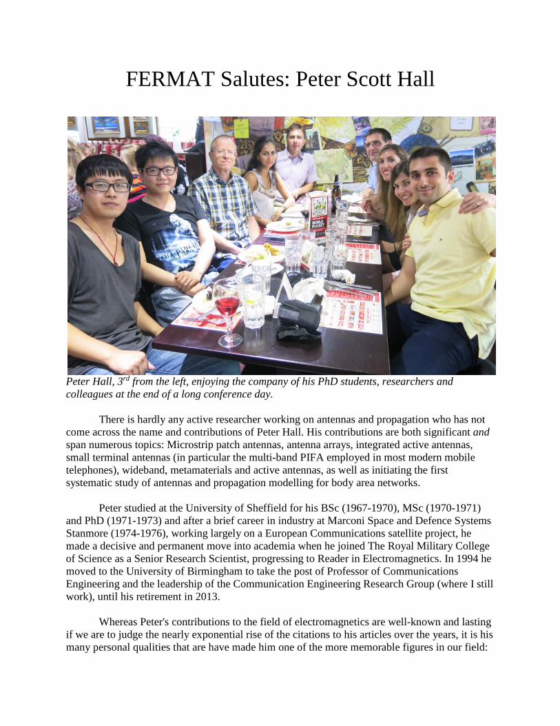
FERMAT Salutes: Peter Scott Hall
Peter Hall, 3rd from the left, enjoying the company of his PhD students, researchers and colleagues at the end of a long conference day. There is hardly any active researcher working on antennas and propagation who has not come across the name and contributions of Peter Hall. His contributions are both significant and span numerous topics: Microstrip patch antennas, antenna arrays, integrated active antennas, small terminal antennas (in particular the multi-band PIFA employed in most modern mobile telephones), wideband, metamaterials and active antennas, as well as initiating the first systematic study of antennas and propagation modelling for body area networks. Peter studied at the University of Sheffield for his BSc (1967-1970), MSc (1970-1971) and PhD (1971-1973) and after a brief career in industry at Marconi Space and Defence Systems Stanmore (1974-1976), working largely on a European Communications satellite project, he made a decisive and permanent move into academia when he joined The Royal Military College of Science as a Senior Research Scientist, progressing to Reader in Electromagnetics. In 1994 he moved to the University of Birmingham to take the post of Professor of Communications Engineering and the leadership of the Communication Engineering Research Group (where I still work), until his retirement in 2013. Whereas Peter's contributions to the field of electromagnetics are well-known and lasting if we are to judge the nearly exponential rise of the citations to his articles over the years, it is his many personal qualities that are have made him one of the more memorable figures in our field:
One of his unique traits is his quiet and unassuming leadership – he has been capable of steering his research group into new areas of research, without any of us even noticing. The RF and microwave engineering research has grown from 5 to 12 faculty members during his time at Birmingham, and his range of research activities has also grown spectacularly. Peter has always had the essential knack of spotting promising new research areas at an early stage and making a lasting mark in a diverse number of areas: reconfigurable antennas, cognitive radio and on-body propagation being among the more recent examples. However, Peter's true contribution only becomes clear when you speak to the PhD students and researchers that he has educated over the years to appreciate the esteem and genuine respect in which they all hold him. To quote the current head of the School of Electronic, Electrical and Computer Engineering at the University of Birmingham, Dr Peter Gardner (also a member of Peter's research group), "he has been a source of inspiration to generations of students at UG, masters and PhD levels, to contract researchers and to junior and senior academic staff alike. We can all learn a lot from his version of the Socratic technique, used equally effectively in interviews, supervision meetings, oral examinations or constructive criticism of papers and proposals. It starts with insightful but disarmingly simple questions, proceeds through graded levels of difficulty and culminates in figuratively pushing you off a cliff, in a very gentlemanly manner, to make you realise that however clever you are or think you are, there are limits to your knowledge, understanding and insight that you need to work on." Peter's highly distinguished research career on an international level, has also been marked by his contributions to the world-wide antennas and propagation community: He is a Fellow of the IET and the IEEE and a past IEEE Distinguished Lecturer; he is a past Chairman of the IEE Antennas and Propagation Professional Group and past coordinator for Premium Awards for IEE Proceedings on Microwave, Antennas and Propagation; he is a member of the IEEE AP-S Fellow Evaluation Committee and has helped organise (and chaired) numerous conferences. His contributions have been recognised through prestigious awards, the 1990 IEE Rayleigh Book Award for the Handbook on Microstrip Antennas, the 2009 LAPC IET James Roderick James Lifetime Achievement Award and the 2012 IEEE John Kraus Antenna Award. It is fitting that a new mode of scientific communication in electromagnetics has one of its first issues dedicated to Peter Hall who has made pioneering contributions to so many areas of antennas and propagation. His legacy to our field will be lasting and will inspire generations of researchers to come.
Dr Costas Constantinou Reader in Communications Engineering & Director of Research School of Electronic, Electrical & Computer Engineering University of Birmingham, Edgbaston Birmingham, B15 2TT, UK
Antenna and Applied Electromagnetics Lab
Cognitive Radio Dr James Kelly
Research Fellow
Dr Peter Gardner, Prof. Peter Hall Dr Farid Ghanem, Elham Ebrahimi, Mohamad Hamid
Keeping a low profile A personal history of the
microstrip antenna
An LAPC 2009 Pre-Dinner talk by
Professor Peter Hall

On Saturday 6 December 1952, La Traviata was about to be performed at Sadlers Wells Opera House in London. The curtain went up. Someone coughed, and those in front turned around to stare at them. The coughing stopped and all began to enjoy the performance. A little later, there was more coughing. People looked round again, but could see those coughing less clearly. Suddenly, they began to cough themselves. Finally, the performance was abandoned at the interval. The incessant coughing of the audience had become intolerable due to the dense ‘pea-souper’ smog which had been slowly creeping into the auditorium making the stage almost invisible to the people who sat further back.

Further west across London the greyhound racing at the White City stadium was halted when the dogs couldn’t see the hare. A Mallard duck, flying blindly across London smashed into Victoria station and crash-landed onto Platform 6. But while there was mist and darkness in the UK, there was a project in progress in the Federal Telecommunications Labs in the USA that was to revolutionise the world of antennas


In October 1953, a seminal paper was presented at the Third Symposium on the USAF Antenna Research and Development Program, at Allerton Park in Illinois, USA.

I was honoured to attend the 33rd Allerton Antenna Symposium in 2009, which is a direct descendent of that 1953 meeting.

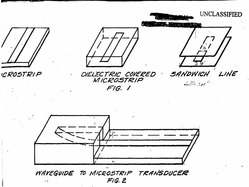
In ‘53 a paper was given that was entitled…. ‘Microstrip Microwave Antenna’, by Deschamps and Sichak. The background to the paper was that, in the few years leading up to it, there had been much work on the newly invented microstrip, which in its own right was revolutionising the world of microwave circuits. It was, as its name implied, a miniaturised form of microwave transmission line, as the paper shows.
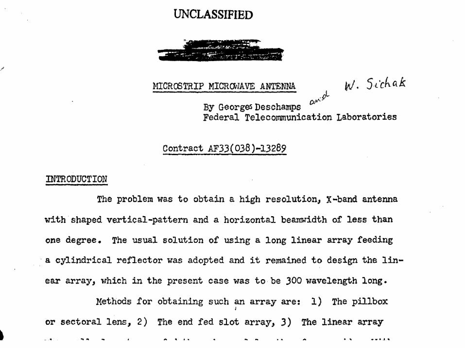
We see microstrip, top left, dielectric covered microstrip, top middle, and on the right, sandwich line, which I think we would now call triplate stripline. The paper also showed a transition from waveguide to microstrip, as I assume many of the high power sources were still in waveguide.
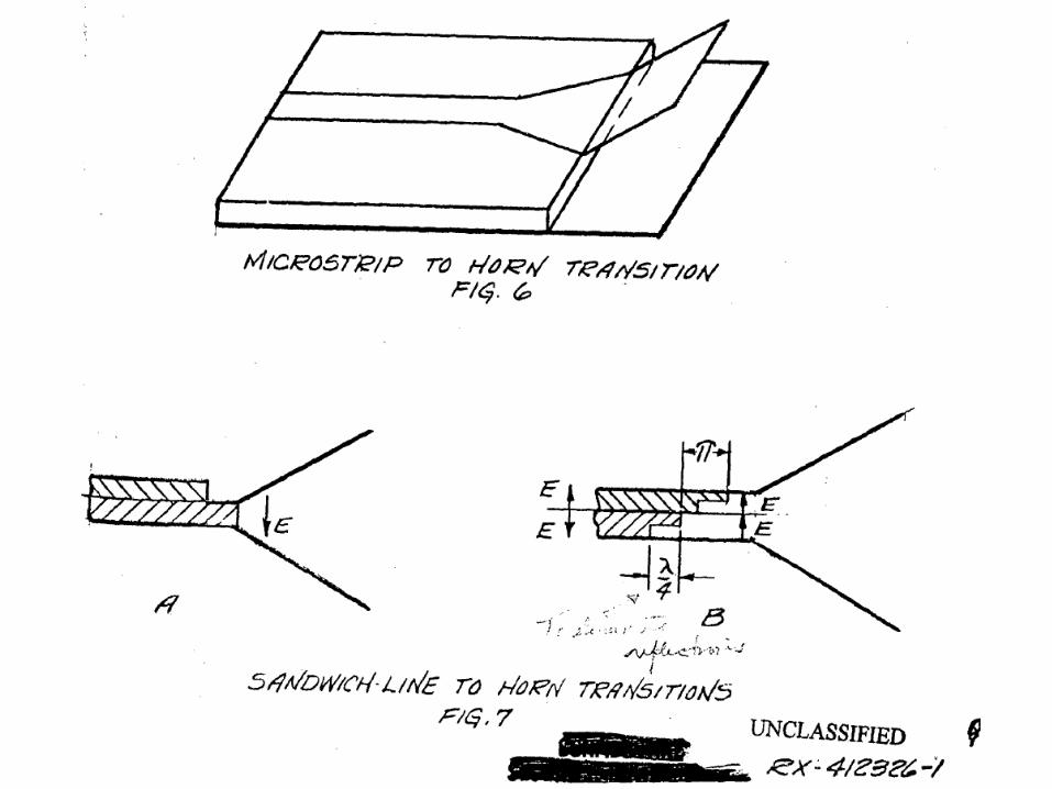
Perhaps the most interesting figure is of the microstrip to horn transition, showing just how simple a microstrip antenna could be. There was of course no reference to anything that looked like a patch antenna, although it was known that microstrip did radiate at transitions, junctions and bends. The paper went on to describe a long horn in this form fed by a microstrip power divider. So, what was driving this research?

Here are Kruschev and Kennedy, locked in the cold war battle, each ready to press the button and initiate the war to end all wars, also called MAD, mutually assured destruction. As part of the whole arsenal of each side, radar was crucial for the detection of incoming planes and missiles.

These are typical radars of the time, firstly a height finding radar.
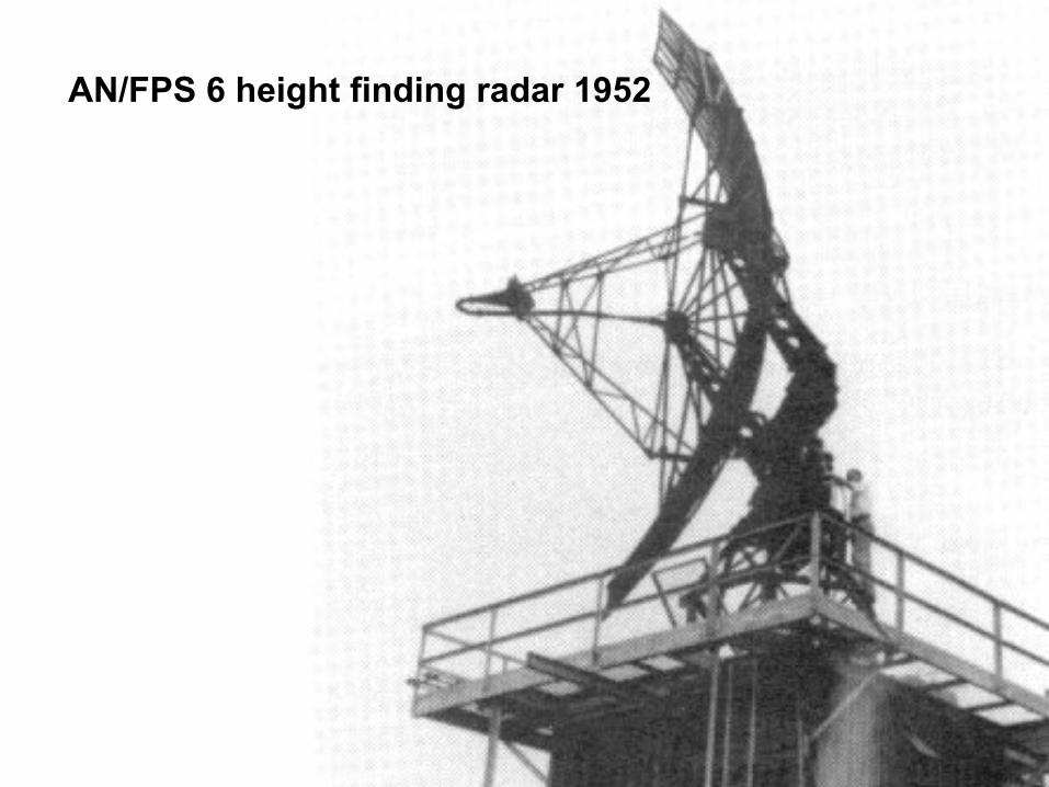
AN/FPS 6 height finding radar 1952

And then a mobile range and direction finding radar. Of course we see the reflector antenna dominant. These radars worked, but faster more agile antennas were needed.

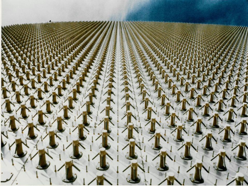
Such agility could only be accomplished using electronically steered phased arrays. This is a later one, called PAVE PAWS. It was deployed to detect intercontinental ballistic missiles.
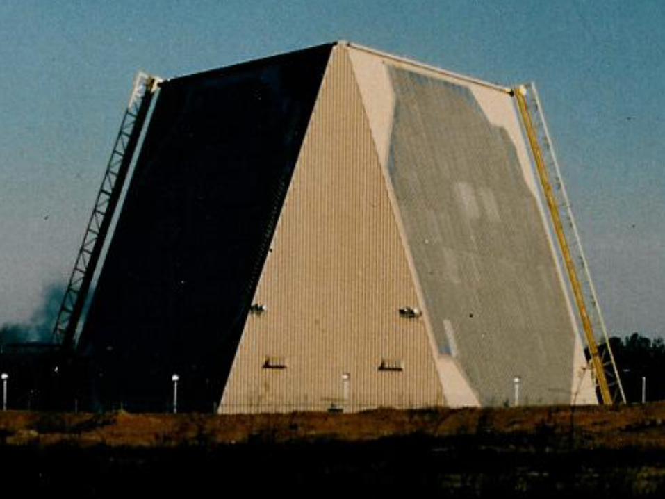
You can see the crossed dipoles and small posts deployed to reduce the mutual coupling. The complexity and cost were enormous, and it was clear that simplification was needed. After the 1953 paper by Deschamps and Sichek, there was a gap of 17 years, before the first paper showing what we now recognise as a patch antenna.
It was in this paper, ‘Very wideband phased arrays’, by Cheston, Byron and Laughlin, given at the Phased Array Antennas Symposium, in Farmingdale. Just why there was this gap of 17 years is still not clear. Perhaps the patch was developed earlier but was not published. Or perhaps the substrates were just not good enough. We will probably never know.
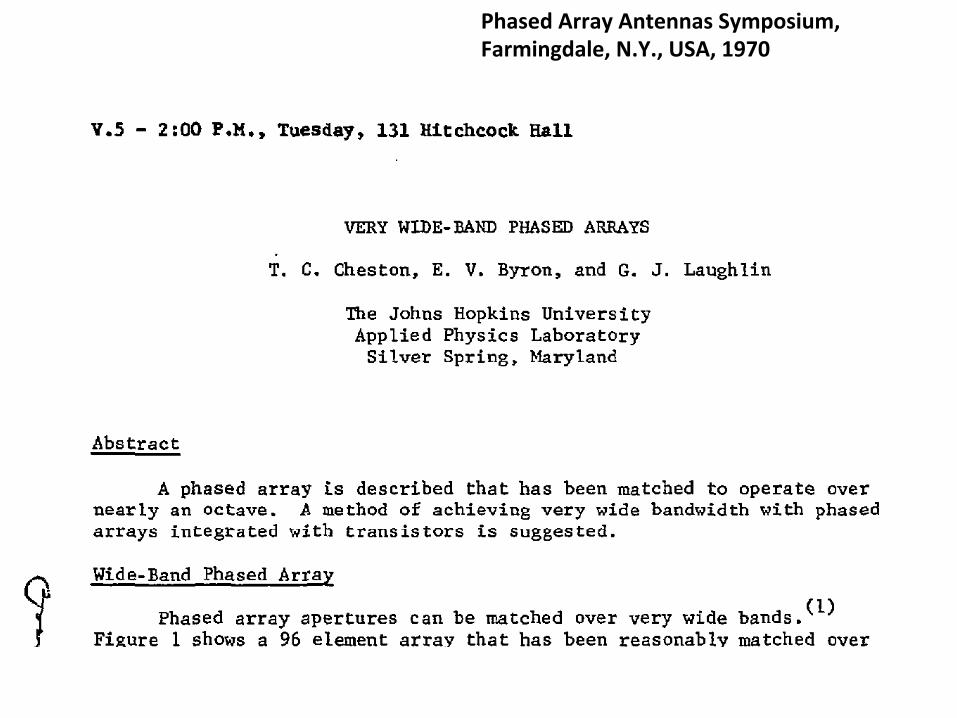
Phased Array Antennas Symposium, Farmingdale, N.Y., USA, 1970
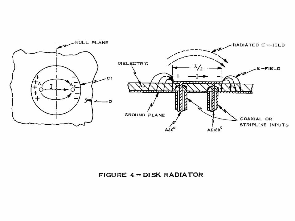
But there it is, the first published figure of the microstrip patch antenna, as a disk radiator for a phased array application. Two out-of-phase feeds, giving the well known fundamental mode, with fringing fields, and radiating fields. I first saw the disc radiator in 1975. I was working for Marconi at Stanmore, London and we were visiting Marconi Research Labs at Great Baddow, Chelmsford, to oversee a reflector antenna contract. The disc antenna was being studied by John Mark and his group. I probably thought that the 2 metre diameter satellite reflector antenna that we were working on was much more impressive than this insignificant disc antenna. Little did I realise then how much it would influence my life.
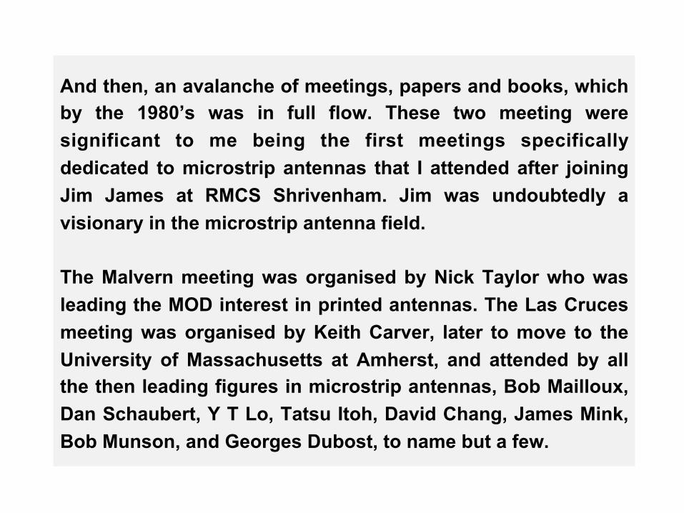
And then, an avalanche of meetings, papers and books, which by the 1980’s was in full flow. These two meeting were significant to me being the first meetings specifically dedicated to microstrip antennas that I attended after joining Jim James at RMCS Shrivenham. Jim was undoubtedly a visionary in the microstrip antenna field. The Malvern meeting was organised by Nick Taylor who was leading the MOD interest in printed antennas. The Las Cruces meeting was organised by Keith Carver, later to move to the University of Massachusetts at Amherst, and attended by all the then leading figures in microstrip antennas, Bob Mailloux, Dan Schaubert, Y T Lo, Tatsu Itoh, David Chang, James Mink, Bob Munson, and Georges Dubost, to name but a few.
1970 onwards – an avalanche of meetings, books and papers
• 1978 Symposium on Flat Plate Antennas, RSRE
Malvern, UK
• 1979 Workshop on Printed Circuit Antenna
Technology, Las Cruces, New Mexico, USA.

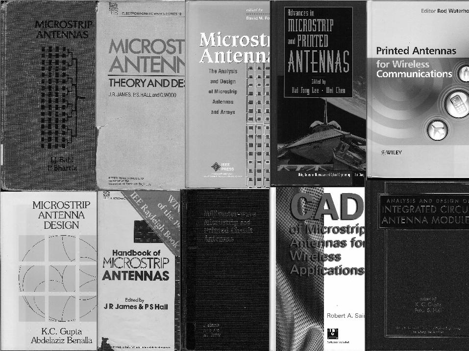
And then there were books and books and books. I apologise if I have omitted anyone’s favourite, or worse still anyone’s book. Bahl and Bhartia 1980, James, Hall and Wood 1981, Gupta and Benalla 1988 James and Hall 1989 Bhartia, Rao and Tomar 1990 Pozar and Schaubert 1995 Sainati 1996 Lee and Chen 1997 Gupta and Hall 2000 Waterhouse 2007
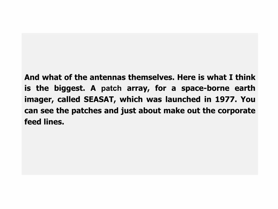
And what of the antennas themselves. Here is what I think is the biggest. A patch array, for a space-borne earth imager, called SEASAT, which was launched in 1977. You can see the patches and just about make out the corporate feed lines.
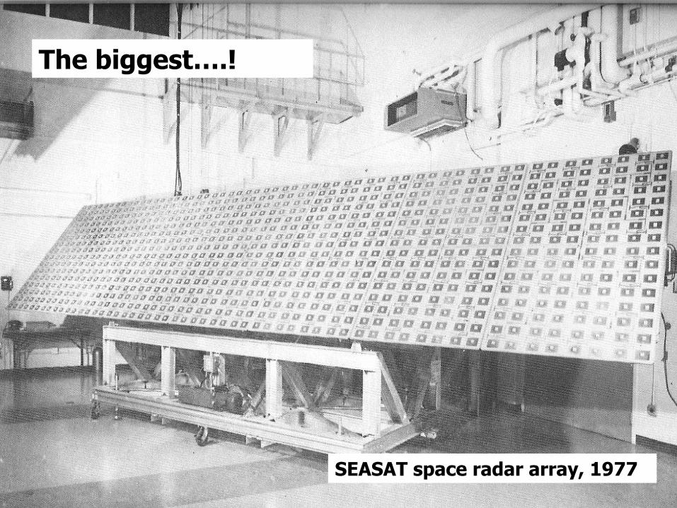
The biggest….? The biggest….!
SEASAT space radar array, 1977
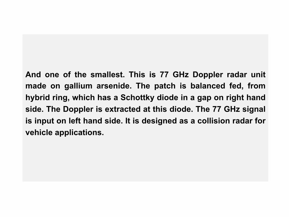
And one of the smallest. This is 77 GHz Doppler radar unit made on gallium arsenide. The patch is balanced fed, from hybrid ring, which has a Schottky diode in a gap on right hand side. The Doppler is extracted at this diode. The 77 GHz signal is input on left hand side. It is designed as a collision radar for vehicle applications.
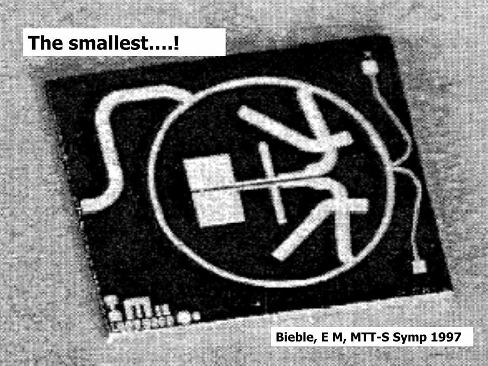
The smallest….!
Bieble, E M, MTT-S Symp 1997
One of the things that happened in the 70’s and 80’s was an explosion in the variety of patch shapes examined. Here are a few, noted in Bahl and Bhartia’s book. Because there is, of course, complete freedom to make a patch any shape, it became a incredibly fertile time for analysis and design. The square and circular were looked at first. Some of the others gave useful differences, in the pattern or in the frequency domains.
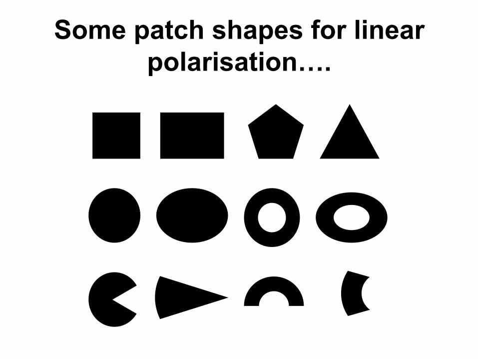
Some patch shapes for linear polarisation….
Then by adding a slot the patch became dual frequency. And by putting the slot in the middle of the patch at 45 degrees, you can get circular polarisation, or you can cut the diagonal corners off, or make the square slightly rectangular, or the circle slightly elliptical. There are literally hundreds of variants.

Some patch shapes for dual frequency….

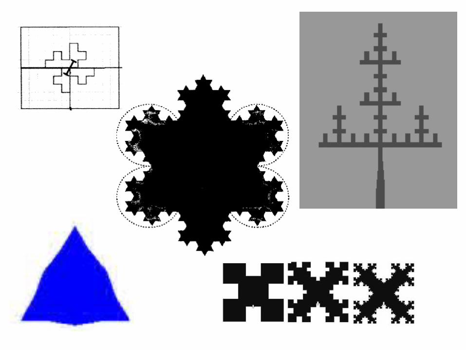
And then there was the fractal concept, which threw up another new set of shapes with interesting properties. The outcome of this freedom is two fold. Firstly it makes writing patents hard, because smart engineers can always work round the patent to get the same result Secondly journal editors become uneasy when another shape comes in with the same performance and they have had so many similar ones already.
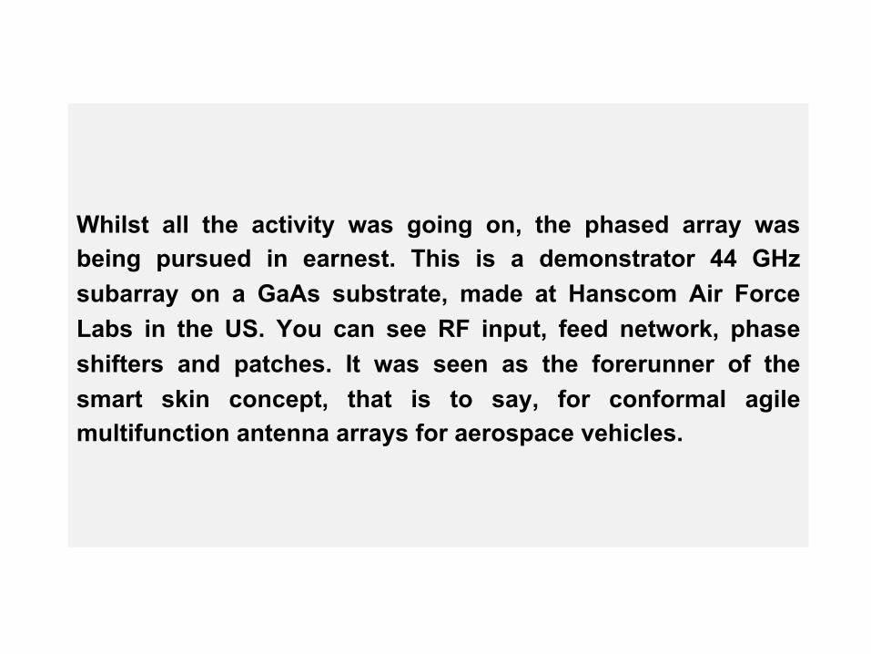
Whilst all the activity was going on, the phased array was being pursued in earnest. This is a demonstrator 44 GHz subarray on a GaAs substrate, made at Hanscom Air Force Labs in the US. You can see RF input, feed network, phase shifters and patches. It was seen as the forerunner of the smart skin concept, that is to say, for conformal agile multifunction antenna arrays for aerospace vehicles.
McIlvenna, J.F.; Schindler, J.K.; MILCOM 88
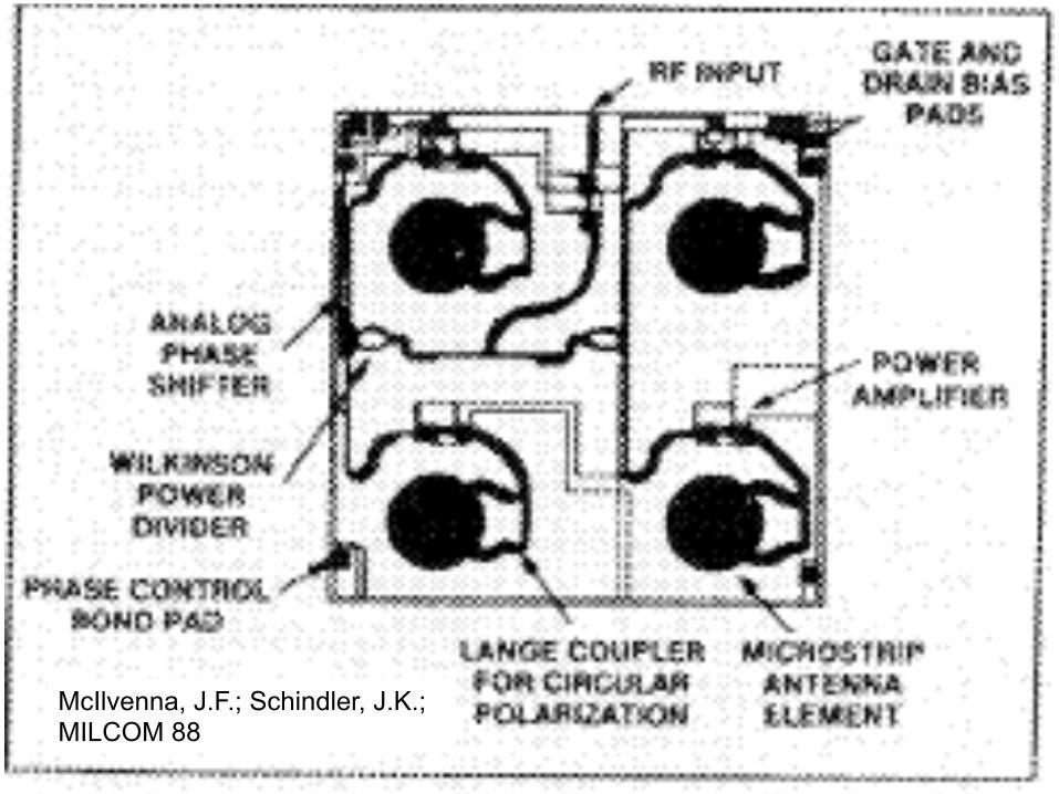
In parallel with practical work, a bril l iant, young electromagneticist, David Pozar, analysed the scan blindness phenomenon in millimeter wave phased arrays, and this graph is the key result. As you can see, as the scan angle - horizontal axis - increases, the active reflection coefficient - on the vertical axis -, increase very quickly, indeed really too quickly, giving total scan blindness at about 45 degrees, in the E plane which is the solid line. This is primarily due to energy being trapped in the surface wave and it has enormous consequences for the type of array in the previous slide, and forces designers to either break up the substrate to prevent the wave from becoming dominant, or to apply EBG concepts.
Pozar, D.M.; Schaubert, D.H.; IEEE Trans AP 1984
E plane scan blindness
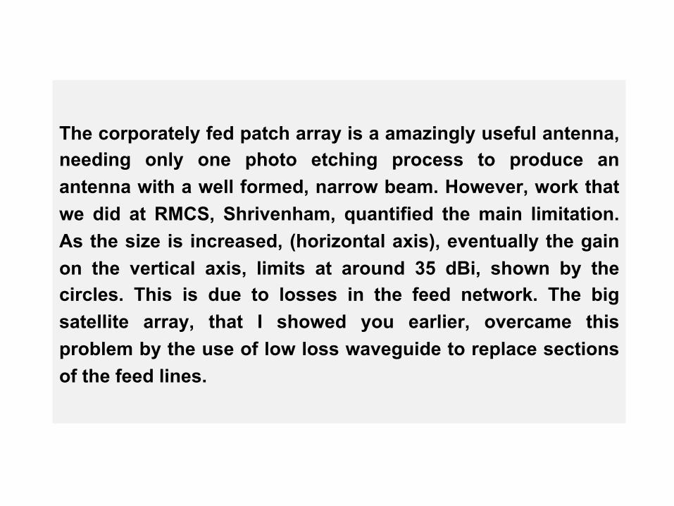
The corporately fed patch array is a amazingly useful antenna, needing only one photo etching process to produce an antenna with a well formed, narrow beam. However, work that we did at RMCS, Shrivenham, quantified the main limitation. As the size is increased, (horizontal axis), eventually the gain on the vertical axis, limits at around 35 dBi, shown by the circles. This is due to losses in the feed network. The big satellite array, that I showed you earlier, overcame this problem by the use of low loss waveguide to replace sections of the feed lines.
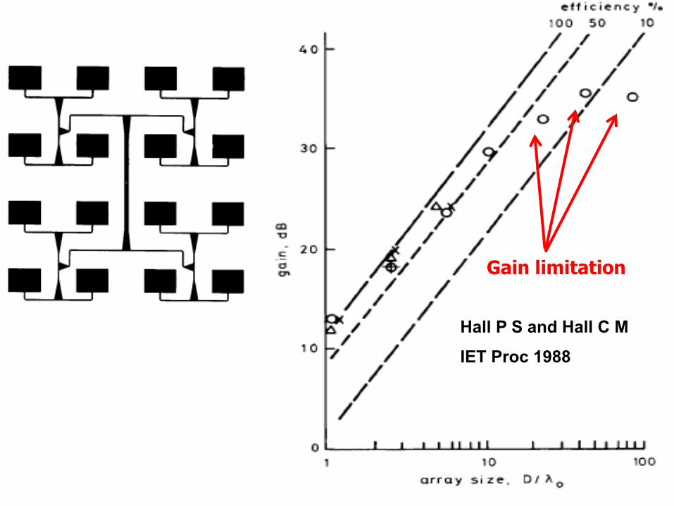
Hall P S and Hall C M
IET Proc 1988
Gain limitation
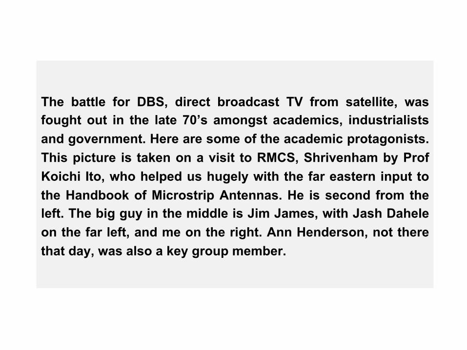
The battle for DBS, direct broadcast TV from satellite, was fought out in the late 70’s amongst academics, industrialists and government. Here are some of the academic protagonists. This picture is taken on a visit to RMCS, Shrivenham by Prof Koichi Ito, who helped us hugely with the far eastern input to the Handbook of Microstrip Antennas. He is second from the left. The big guy in the middle is Jim James, with Jash Dahele on the far left, and me on the right. Ann Henderson, not there that day, was also a key group member.

The battle for DBS (direct broadcast TV from satellite)
Jim had come up with an array concept called the comb line array, which we all worked on. He got the people at the BBC Research Centre at Kingswood Warren interested in it as a possible DBS antenna, so Ann put together the demonstrator.
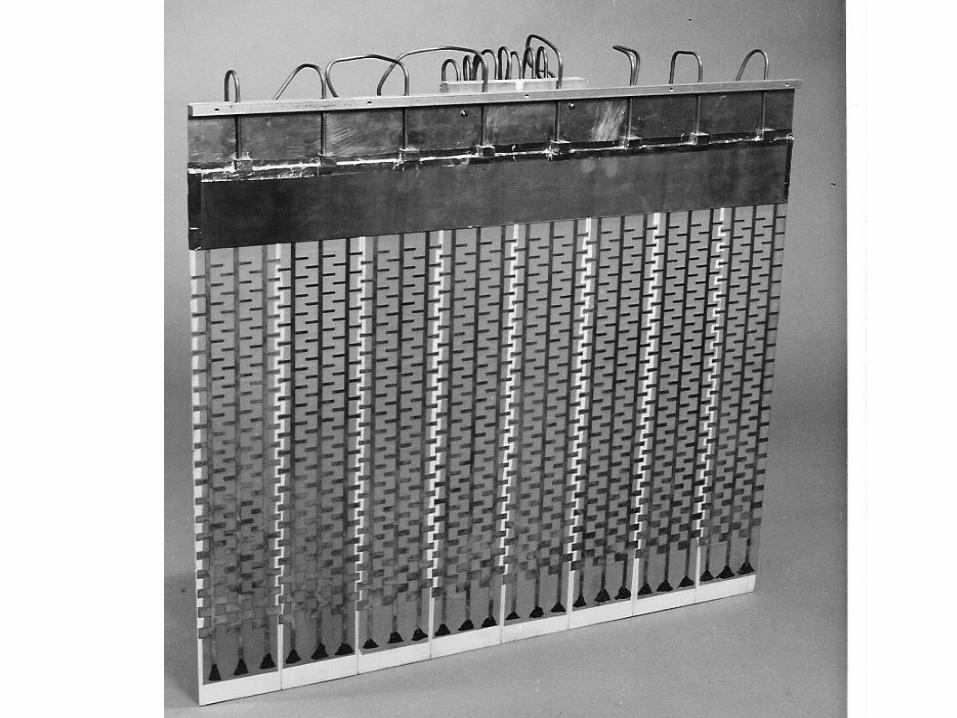

The BBC Research Centre had a big reputation. They used to say that the BBC people were so good, and their internal reports so well written, that they would just tear off the front cover and submit them to IEE Proceedings.

The contenders for the coveted DBS antenna position were the flat plate array, as shown on the left. In the British Satellite Broadcasting incarnation, it was called the Squarial. The other contender was the offset reflector. Jim presented our work, at an IEE colloquium, and I remember a wonderful and heated argument on the floor of the meeting, between him and David Olver, from Queen Mary, who of course took the reflector position.
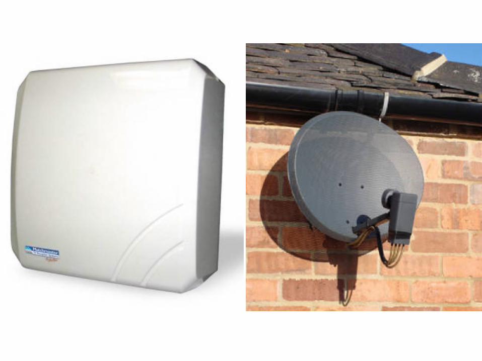
The argument was that the array could be low profile, and hence much less obtrusive, and when you look at these pictures of a horn array DBS antenna, which I recently came across, you can begin to see it, or rather, as intended, not see it. On the other hand the reflector argument was that it was very low cost and very easy to build. The Squarial effectively lost the battle when the Marcopolo satellites, that they were designed for, were shut down when BSB merged with Sky to become BSkyB.
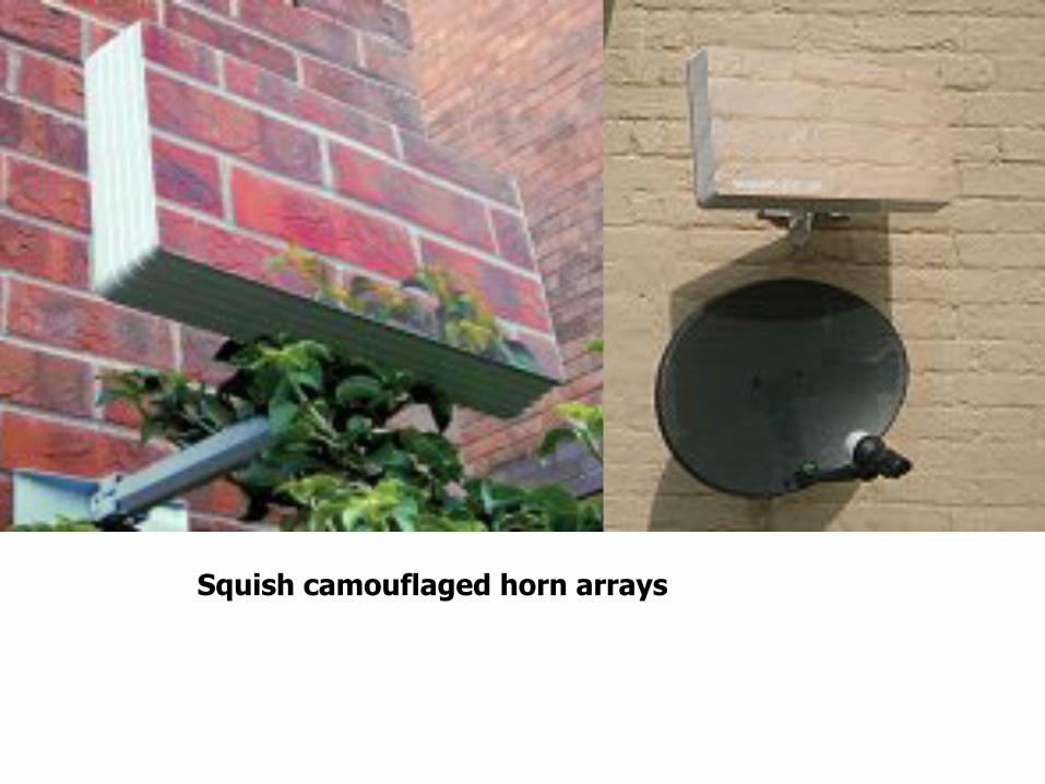
Squish camouflaged horn arrays
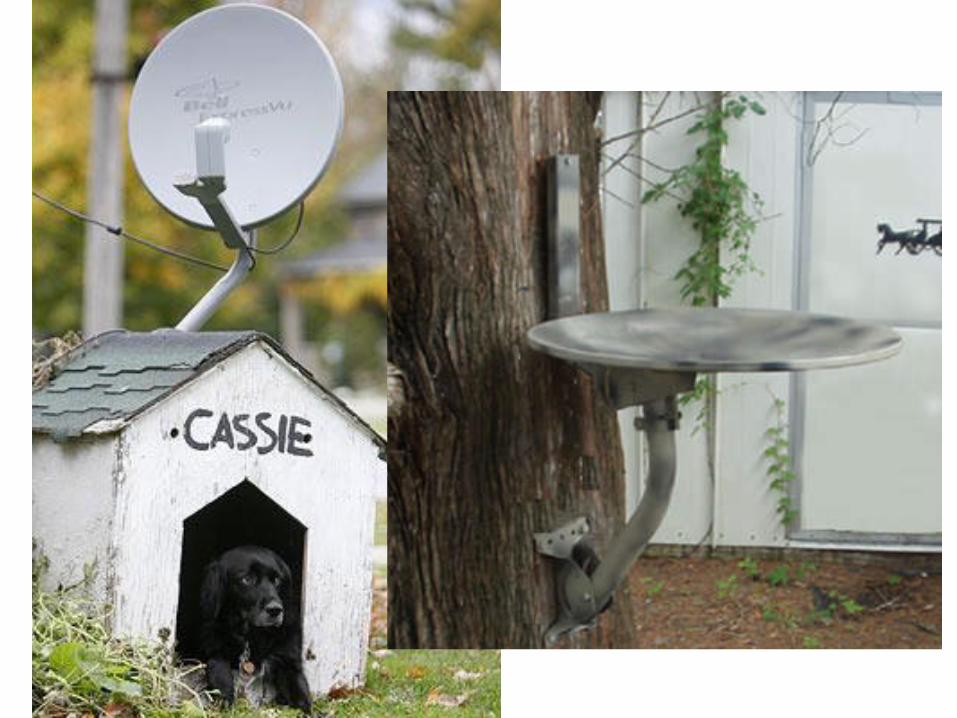
In one sense, microstrip antennas were just flexing their muscles and have won out in many other areas, as part of the wider revolution that is printed circuit antennas. Reflector antennas still have their uses!
As an example of the use of microstrip antennas, many modern mobile base station antennas use patch arrays.
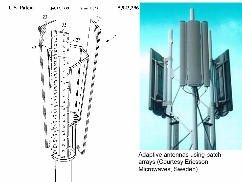
Adaptive antennas using patch arrays (Courtesy Ericsson Microwaves, Sweden)

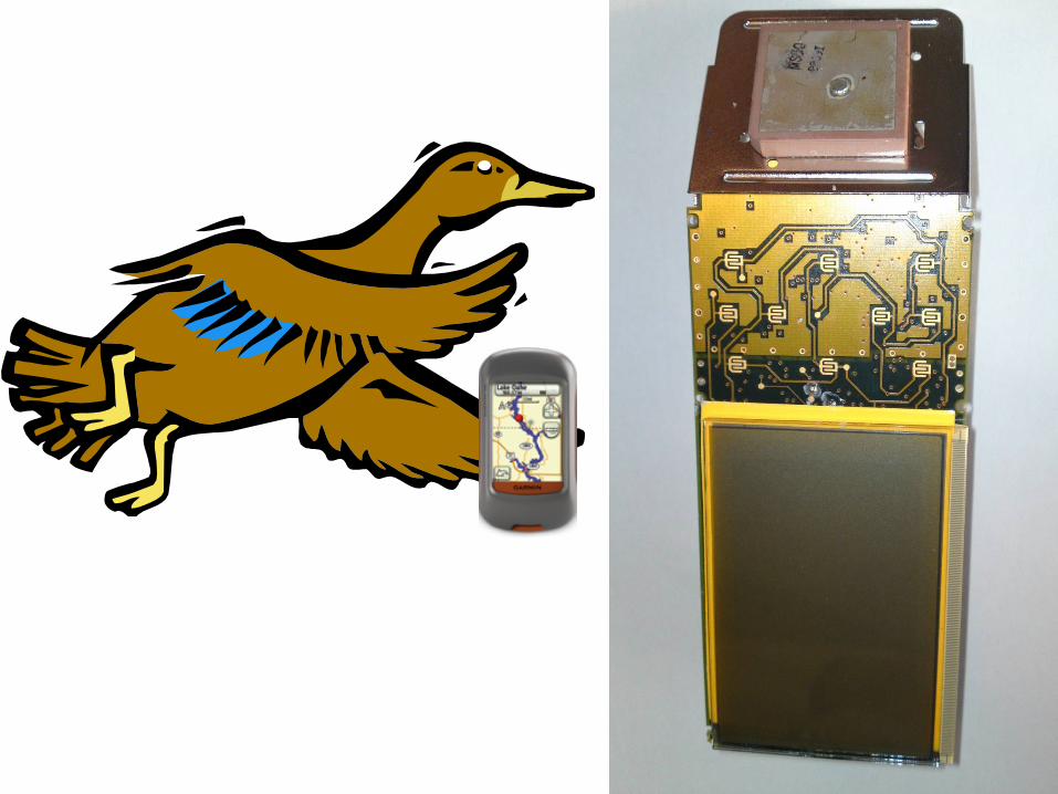
Here is a handheld GPS receiver. It uses a circularly polarised patch antenna on ceramic substrates, and this has been the staple antenna of the GPS receiver market.
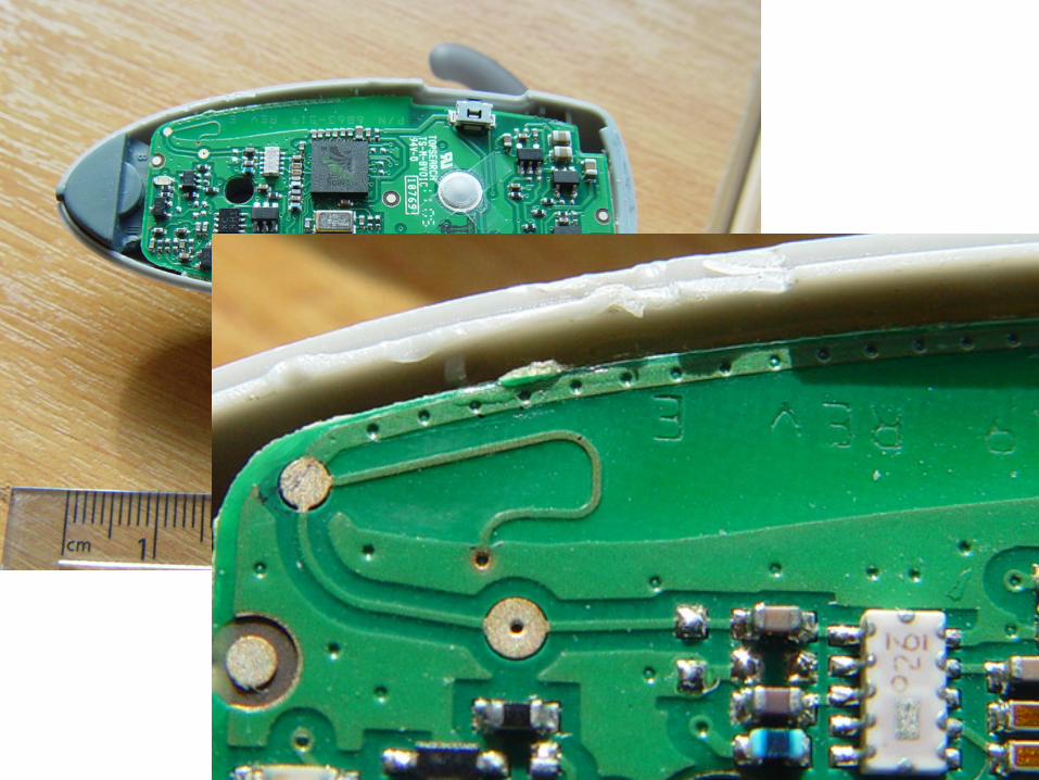
These pictures are an example of what we like to do at Birmingham. We call it antenna forensics. We take apart real wireless products and identify the antenna. It has great educational value and I’m sure you all do it. Because I believe that the microstrip antenna and the printed circuit antenna revolution went hand in hand, the next few forensic examples are not patch antennas but other members of the printed circuit antenna family. Here is an inverted F antenna inside a Bluetooth headset. You can see the radiating conductor on the edge of the pcb. The cost is low being related to the area of extra substrate used. The inverted F is perhaps the uncle of the patch.

Talking about Bluetooth……

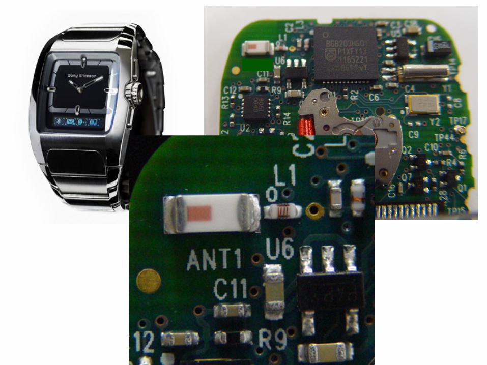
Here is one that gave my students a real problem. They had done the others I showed you, but couldn’t seem to identify anything like an antenna. Its a Bluetooth phone controller in a wristwatch and the pcb is shown top right. Only when you read the lettering on the circuit board, ANT 1, which I blanked in the other picture to make it more fun, do you realise its the antenna. It is of course an LTCC multilayer surface mount printed radiator. I’m not sure what relationship it has to the patch, but it is a widely used printed circuit antenna.

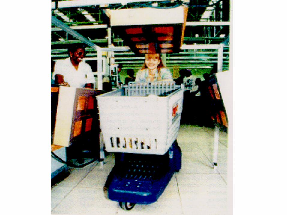
This woman is happy because she can get her food microwaved in the way out of the supermarket! It is actually a demonstrator of an early RFID system, which uses large microstrip patch arrays to interrogate the trolley.
I think that the microstrip antenna was a revolutionary concept that was integral with and important to the move to printed circuit antennas and changed the way that antenna designers think. Thank you and enjoy your dinner.

Antenna and Applied Electromagnetics Lab
Cognitive Radio Dr James Kelly
Research Fellow
Dr Peter Gardner, Prof. Peter Hall Dr Farid Ghanem, Elham Ebrahimi, Mohamad Hamid
Keeping a low profile
Enjoy the dinner!