fen01 ethernet communication card operation ... dvp-fen01 ethernet communication card operation...
TRANSCRIPT

www.deltaww.com
DVP-FEN01 EthernetCommunication CardOperation Manual
2014-03-05
Industrial Automation HeadquartersDelta Electronics, Inc. Taoyuan Technology CenterNo.18, Xinglong Rd., Taoyuan City, Taoyuan County 33068, TaiwanTEL: 886-3-362-6301 / FAX: 886-3-371-6301
AsiaDelta Electronics (Jiangsu) Ltd.Wujiang Plant 31688 Jiangxing East Road, Wujiang Economic Development ZoneWujiang City, Jiang Su Province, P.R.C. 215200TEL: 86-512-6340-3008 / FAX: 86-769-6340-7290
Delta Greentech (China) Co., Ltd.238 Min-Xia Road, Pudong District, ShangHai, P.R.C. 201209TEL: 86-21-58635678 / FAX: 86-21-58630003 Delta Electronics (Japan), Inc.Tokyo Office 2-1-14 Minato-ku Shibadaimon, Tokyo 105-0012, JapanTEL: 81-3-5733-1111 / FAX: 81-3-5733-1211
Delta Electronics (Korea), Inc.1511, Byucksan Digital Valley 6-cha, Gasan-dong, Geumcheon-gu, Seoul, Korea, 153-704TEL: 82-2-515-5303 / FAX: 82-2-515-5302
Delta Electronics Int’l (S) Pte Ltd.4 Kaki Bukit Ave 1, #05-05, Singapore 417939TEL: 65-6747-5155 / FAX: 65-6744-9228
Delta Electronics (India) Pvt. Ltd.Plot No 43 Sector 35, HSIIDC Gurgaon, PIN 122001, Haryana, India TEL : 91-124-4874900 / FAX : 91-124-4874945
AmericasDelta Products Corporation (USA)Raleigh OfficeP.O. Box 12173,5101 Davis Drive, Research Triangle Park, NC 27709, U.S.A.TEL: 1-919-767-3800 / FAX: 1-919-767-8080
Delta Greentech (Brasil) S.A.Sao Paulo OfficeRua Itapeva, 26 - 3° andar Edificio Itapeva One-Bela Vista01332-000-São Paulo-SP-BrazilTEL: 55 11 3568-3855 / FAX: 55 11 3568-3865
EuropeDeltronics (The Netherlands) B.V.Eindhoven OfficeDe Witbogt 20, 5652 AG Eindhoven, The Netherlands TEL: 31-40-2592850 / FAX: 31-40-2592851
DVP-0206820-01
*We reserve the right to change the information in this manual without prior notice.

i
DVP-FEN01 Ethernet Communication Card
Operation Manual
Contents
Chapter 1 Introduction
1.1 Functions.............................................................................................................. 1-2
1.2 Functional Specifications...................................................................................... 1-3
Chapter 2 Dimensions and Profile
2.1 Dimensions........................................................................................................... 2-2
2.2 Profile ................................................................................................................... 2-2
2.3 Indicators.............................................................................................................. 2-2
2.4 RJ45 Connector ................................................................................................... 2-3
2.5 RS-232 Connector................................................................................................ 2-3
2.6 Troubleshooting.................................................................................................... 2-3
Chapter 3 Installation and Wiring
3.1 Installation ............................................................................................................ 3-2
3.2 Connecting a Network .......................................................................................... 3-3
Chapter 4 Control Registers
4.1 Table of Control Registers in DVP-FEN01 ........................................................... 4-2
4.2 Specifications and Functions................................................................................ 4-3
4.3 Communication Card Number.............................................................................. 4-4
4.4 Introduction of ETHRW ........................................................................................ 4-5
Chapter 5 Setting DVP-FEN01 by Means of Software
5.1 Setting Communication and Searching for Modules ............................................ 5-2
5.2 Basic Settings..................................................................................................... 5-10
5.3 Data Exchange................................................................................................... 5-14
5.4 IP Filter ............................................................................................................... 5-15
5.5 Setting a Password ............................................................................................ 5-16
5.6 Restoring DVP-FEN01 to Its Factory Settings ................................................... 5-17
i i
Chapter 6 Examples
6.1 Connecting WPLSoft to a DVP-EH3 Series PLC by Means of the Ethernet Port on
DVP-FEN01 ......................................................................................................... 6-2
6.2 Connecting WPLSoft to a DVP-EH3 Series PLC by Means of the RS-232 Port on
DVP-FEN01 ......................................................................................................... 6-5
6.3 Setting/Removing a Password ............................................................................. 6-8
6.4 Lost Password (Restoring DVP-FEN01 to Its Factory Settings by Means of RS-232)
........................................................................................................................... 6-12
6.5 Setting an IP Filter.............................................................................................. 6-15
6.6 Always Enabling Data Exchange ....................................................................... 6-17
6.7 Enabling Data Exchange by Means of a Program ............................................. 6-19
6.8 Enabling Data Exchange by Means of the RUN/STOP switch on a PLC........... 6-21
6.9 Application of ETHRW ....................................................................................... 6-23

i i i

Chapter 1 Introduction
Contents 1.1 Functions.............................................................................................................. 1-2 1.2 Functional Specifications...................................................................................... 1-2
1-1

DVP-FEN01 Ethernet Communicat ion Card Operat ion Manual
Thanks for using the communication card DVP-FEN01. To ensure that the product is correctly installed and operated, users need to read the operation manual carefully before they use DVP-FEN01. DVP-FEN01 is an Ethernet communication card. It supports a standard Modbus TCP communication protocol. It can pass the Modbus TCP data received to the PLC to which it is connected. Besides, the PLC to which it is connected can send Modbus TCP data to other devices on Ethernet. It supports Delta PLC software. Users can use Ethernet or a RS-232 cable to upload the program in a PLC/download a program to a PLC and monitor a program through DVP-FEN01. The operation manual provides functional specifications, and introduces installation, basic operation and
setting, and communication protocols. The product is the communication card used used with a PLC. If users want to use this product, they have
to install it in a DVP-EH3 series PLC. (It only supports a DVP-EH3 series PLCs whose firmware version is 1.12 or above.)
Please refer to an instruciton sheet for more inforation about the environment in which a PLC can be installed and points for attention.
Please check the wiring of a PLC before the PLC is powered. Do not touch any terminal when a PLC is powered.
In order to prevent the product from being damaged, or prevent staff from being hurt, users need to read the operation manual carefully, and follow the instructions in the manual.
1.1 Functions
It provides DVP-EH3 series PLCs with an Ethernet communication function. It is equipped with an Ethernet port and an RS-232 port. The Ethernet port automatically detects the transmission speed of 10/100 Mbps. The Ethernet protocols it supports are ARP, IP, TCP, UDP, DHCP, and Modbus TCP. There are eight Modbus TCP clients (for sending packets), and four Modbus TCP servers (for receiving
packets). It supports four IP filters. The IP addresses which can not be accessed can be filtered out. Users can use Ethernet or a RS-232 cable to upload the program in a PLC/download a program to a PLC
and monitor a program through DVP-FEN01. The Modbus ASCII communication format that the RS-232 port on a DVP-EH3 series PLC supports is “19200, 8, N, 1”.
1.2 Functional Specifications
Communication interface Ethernet interface Connector RJ45 with an auto-MDI/MDIX Number of ports 1 port Cable 100 meter cat 5e cable is used. Transmission speed The transmittion speed of 10/100 Mbps is automatically detected. Communication protocol ARP, IP, TCP, UDP, DHCP, Modbus TCP, Delta configuration
RS-232 interface Connector Mini DIN Number of ports 1 port Cable DVPACAB215/DVPACAB230/DVPACAB2A30 Transmission speed 19,200 bps Communiucation format Data bit: 8 Parity bit: None Stop bit: 1 Communication protocol Modbus ASCII
Electrical specifications
Power voltage 5 V DC (supplied through the connector on a PLC) Power consumption 1 W
Weight 16 g
1-2

Chapter 1 In t roduct ion
Environmental specifications
Noise immunity ESD (IEC 61131-2, IEC 61000-4-2): 8 kV air discharge EFT (IEC 61131-2, IEC 61000-4-4): communication I/O: ±2 kV CS (IEC 61131-2, IEC 61000-4-6): 0.15~80 MHz, 3 Vrms
Operation/Storage Operation: 0°C~55°C (Temperature), 50~95% (Humidity), pollution degree 2Storage: -25°C~70°C (Temperature), 5~95% (Humidity)
Vibration/Shock resistance
International standards IEC 61131-2, IEC 68-2-6 (TEST Fc)/IEC 61131-2 & IEC 68-2-27 (TEST Ea)
1-3

DVP-FEN01 Ethernet Communicat ion Card Operat ion Manual
1-4
MEMO

Chapter 2 Dimensions and Profile
Contents 2.1 Dimensions........................................................................................................... 2-2 2.2 Profile ................................................................................................................... 2-2 2.3 Indicators.............................................................................................................. 2-2 2.4 RJ45 Connector ................................................................................................... 2-3 2.5 RS-232 Connector................................................................................................ 2-3 2.6 Troubleshooting.................................................................................................... 2-3
2-1

DVP-FEN01 Ethernet Communicat ion Card Operat ion Manual
2.1 Dimensions
Unit: mm (Exclusive of the DIP)
2.2 Profile
Mounting hole
Connector
RS-232 port
RJ45 port
Activity LED indicator (Orange)
Link LED indicator (Green)
Draw bar for removing a communication card
1
2
3 4
7
6
5
8
(Back) (Side) (Front)
Firmware update switch (Please make sure that the switch is turned OFF before DVP-FEN01 is used.)
2.3 Indicators
Indicator State Indication ON An Ethernet connection is successful.
Link LED indicator Green OFF An Ethernet connection fails.
Blinking Data is being sent/received through Ethernet. Activity LED indicator Oragne
OFF No data is sent/received.
2-2

Chapter 2 Dimensions and Prof i le
2.4 RJ45 Connector
Pin RJ45 Pin RJ45
1 Tx+ 5 N/C
2 Tx- 6 Rx-
3 Rx+ 7 N/C
4 N/C 8 N/C
2.5 RS-232 Connector
Pin Mini DIN Pin Mini DIN
1 N/C 5 Tx
2 N/C 6 N/C
3 N/C 7 N/C
4 Rx 8 GND
2.6 Troubleshooting
Problem Reason Solution
The PLC used is not powered. Please check whether the PLC is powered, and check whether the power supplied to the PLC is normal.
DVP-FEN01 is not connected to the PLC used.
Please check whether DVP-FEN01 is connected to the PLC.
Link LED indicator is OFF.
Ethernet connection failure Please check whether the network cable used is connected correctly.
2-3

DVP-FEN01 Ethernet Communicat ion Card Operat ion Manual
2-4
MEMO

Chapter 3 Installation and Wiring
Contents 3.1 Installation ............................................................................................................ 3-2 3.2 Connecting a Network .......................................................................................... 3-3
3-1

DVP-FEN01 Ethernet Communicat ion Card Operat ion Manual
The combination of DVP-FEN01 with a PLC, and the connection of DVP-FEN01 to a network are introduced.
3.1 Installation
Before users install a communication card in a PLC or remove a communication card from a PLC, they have to turn off the PLC, and open the cover of the slot, as shown below.
1. Installing a communication card: Put a communication card into the slot, and tighten a screw.
2. Removing a communication card
3. Inspection after installation Users have to power a PLC, and connect a network cable to the RJ45 port on DVP-FEN01 correctly. If the Link LED indicator is ON, the PLC and DVP-FEN01 are connected correctly and powered normally. Then, the users have to open DCISoft. In DCISoft, the users have to select the communication port (the RS-232 port or the Ethernet port) which is connected to the communication card, and related parameters. They have to click Search or IP search on the toolbar. After search is complete, the icon representing the communication card and the name DVP-FEN01 will be displayed in DCISoft. After the users click the icon, they can set network parameters such as an IP address.
3-2
Chapter 3 Instal lat ion and Wir ing
3.2 Connecting a Network
The users have to connect DVP-FEN01 to an Ethernet hub by means of a cat 5e cable. DVP-FEN01 is equipped with an auto-MDI/MDIX function, and therefore a cat 5e cable is used, and no jump wire is needed. The maximum length of a cable is 100 meter.
3-3

DVP-FEN01 Ethernet Communicat ion Card Operat ion Manual
3-4
MEMO

Chapter 4 Control Registers
Contents 4.1 Table of Control Registers in DVP-FEN01 ........................................................... 4-2 4.2 Descriptions of Control Registers......................................................................... 4-3 4.3 Communication Card Number.............................................................................. 4-4 4.4 Introduction of ETHRW ........................................................................................ 4-5
4-1
DVP-FEN01 Ethernet Communicat ion Card Operat ion Manual
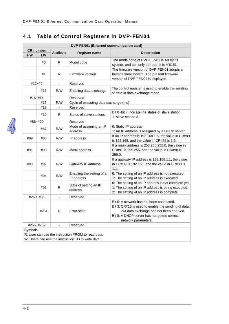
4.1 Table of Control Registers in DVP-FEN01
DVP-FEN01 (Ethernet communication card) CR number HW LW
Attribute Register name Description
#0 R Model code The mode code of DVP-FEN01 is set by its system, and can only be read. It is H’6151.
#1 R Firmware version The firmware version of DVP-FEN01 adopts a hexadecimal system. The present firmware version of DVP-FEN01 is displayed.
#12~#2 - Reserved
#13 R/W Enabling data exchange The control register is used to enable the sending of data in data exchange mode.
#16~#14 - Reserved #17 R/W Cycle of executing data exchange (ms) #18 - Reserved
#19 R States of slave stations Bit 0~bit 7 indicate the states of slave station 1~slave station 8.
#86~#20 - Reserved
#87 R/W Mode of assigning an IP address
0: Static IP address 1: An IP address is assigned by a DHCP server
#89 #88 R/W IP address If an IP address is 192.168.1.5, the value in CR#89 is 192.168, and the value in CR#88 is 1.5.
#91 #90 R/W Mask address If a mask address is 255.255.255.0, the value in CR#91 is 255.255, and the value in CR#90 is 255.0.
#93 #92 R/W Gateway IP address If a gateway IP address is 192.168.1.1, the value in CR#89 is 192.168, and the value in CR#88 is 1.1.
#94 R/W Enabling the setting of an IP address
0: The setting of an IP address is not executed. 1: The setting of an IP address is executed.
#95 R State of setting an IP address
0: The setting of an IP address is not complete yet. 1: The setting of an IP address is being executed. 2: The setting of an IP address is complete.
#250~#96 - Reserved
#251 R Error state
Bit 0: A network has not been connected. Bit 3: CR#13 is used to enable the sending of data,
but data exchange has not been enabled. Bit 8: A DHCP server has not gotten correct
network parameters. #255~#252 - Reserved
Symbols: R: User can use the instruction FROM to read data. W: Users can use the instruction TO to write data.
4-2

Chapter 4 Contro l Regis ters
4.2 Descriptions of Control Registers
CR#0: Model code [Description] 1. Model code of DVP-FEN01=H’6151 2. Users can judge whether DVP-FEN01 exists by means of reading the model code DVP-FEN01 in a
program.
CR#1: Firmware version [Description] The firmware version of DVP-FEN01 adopts a hexadecimal system. For example, H’0100 indicates that the firmware version of DVP-FEN01 is 1.00. Data exchange
CR#13: Enabling data exchange [Description] If the value in CR#13 is 2 when Program Control is selected in the Enable Condition drop-down list box, data exchange will be executed. If the value in CR#13 is 0, the execution of data exchange will stop. (Please refer to section 5.3 for more information.) If PLC Run is selected in the Enable Condition drop-down list box, data exchange is executed when a PLC runs, and the data exchange stops when the PLC stops. If Always Enable is selected in the Enable Condition drop-down list box, data exchange will be executed no matter what value is in CR#13.
CR#17: Cycle of executing data exchange [Description] Users can set or view the time which passes before the next cycle of data exchange is executed. A millisecond is a unit. The default value in CR#17 is 0, that is, the next cycle of data exchange will be executed immediately after the last data is received. If the value in CR#17 is 10, 10 milliseconds pass before the next cycle of data exchange is executed.
CR#19: States of slave stations [Description] Bit 0~bit 7 indicate the sates of slave station 1~slave station 8. If a bit is 1, an error occurs in the slave station corresponding to the bit. Setting an IP address
CR#87: Mode of assigning an IP address [Description] 0: Static IP address 1: Dynamic IP address
CR#88, CR#89: IP address [Description] CR#88 and CR#89 are used to the IP address of DVP-FEN01. Example: If an IP address is 192.168.1.5, the value in CR#89 is H’C0A8 (192.168), and the value in CR#88 is H’0105 (1.5).
CR#90, CR#91: Mask address [Description] CR#90 and CR#91 are used to set the mask address of DVP-FEN01. Example: If a mask address is 255.255.255.0, the value in CR#91 is H’FFFF (255.255), and the value in CR#90 is H’FF00 (255.0).
4-3
DVP-FEN01 Ethernet Communicat ion Card Operat ion Manual
CR#92, CR#93: Gateway IP address [Description] CR#92 and CR#93 are used to set the gateway IP address of DVP-FEN01. Example: If a gateway IP address is 192.168.1.1, the value in CR#92 is H’C0A8 (192.168), and the value in CR#93 is H’0101 (1.1).
CR#94: Enabling the setting of an IP address [Description] CR#94 is used to execute the setting of CR#87~CR#93. If the value in CR#94 is 1, the setting of an IP address is enabled.
CR#95: State of setting an IP address [Description] CR#95 indicates the state of setting an IP address. 0: The setting of an IP address is not complete yet. 1: The setting of an IP address is being executed. 2: The setting of an IP address is complete.
Error state
CR#251: Error state [Description] CR#251 indicates an error state. If an error occurs, the bit corresponding to the error is 1. Bit 0: A network has not been connected Bit 3: CR#13 is used to enable the sending of data, but data exchange has not been enabled. Bit 8: A DHCP server has not gotten correct network parameters.
4.3 Communication Card Number
After DVP-FEN01 is installed, users may need to use a PLC program to control DVP-FEN01. The two instructions FROM and TO can be used to read the data in the control registers in DVP-FEN01 and write data into the control registers in DVP-FEN01. The numbers assigned to the left-side modules are K100~K107, and the number assigned to DVP-FEN01 is K108.
4-4

Chapter 4 Contro l Regis ters
4.4 Introduction of ETHRW
DVP-FEN01 supports the instruction ETHRW. It can send a Modbus TCP command to a device to which an IP address is assigned by means of the instruction. Instruction name: ETHRW (Only the 16-bit instruction is supported.) Format: ETHRW S1 S2 D n (The 32-bit instruction and the pulse instruction are not supported.) Descriptions of the operands: S1: IP address, communication port number, and read/write mode IP address: Two consecutive word devices are occupied, that is S1+0 and S1+1 are occupied.
IP address IP3.IP2.IP1.IP0 192.168.1.6 If S1 is D0, the value in D0 is H’0106, and the value in D1 is H’C0A8.
D100 D101 High Low High Low IP1 IP0 IP3 IP2 1 6 192 168
H’0106 H’C0A8 Communication port number: The number assigned to DVP-FEN01 is K108. It occupies S1+2 (D2). Station address: The station address of a slave occupies S1+3 (D3). Read/Write mode: The definition of a read/write mode is the same as that of Modbus. The function codes
supported are H’03, H’04, H’06, and H’10. The device occupied is S1+4 (D4). S2: It is the communication address of the device which is read/to which data is written. The definition of an
address is the same as that of Modbus. D: Source data register number or destination data register number (data register number stored in a PLC) n: Data length: A word is a unit. n is in the range of K1 to K96. If n is not in the range, it will be counted as the
maximum value or the minimum value. Please refer to a DVP-EH3 manual for more information about flags and points for attention. Models supported: DVP-EH3 (DVP-EH3-L) version 1.20/DVP-SV2 version 1.00/DVP-SE version
1.00/DVP-SA2 version 2.40/DVP-SX2 version 2.40
4-5

DVP-FEN01 Ethernet Communicat ion Card Operat ion Manual
4-6
MEMO

Chapter 5 Setting DVP-FEN01 by Means of Software
Contents 5.1 Setting Communication and Searching for Modules ............................................ 5-2 5.2 Basic Settings..................................................................................................... 5-10 5.3 Data Exchange................................................................................................... 5-14 5.4 IP Filter ............................................................................................................... 5-15 5.5 Setting a Password ............................................................................................ 5-16 5.6 Restoring DVP-FEN01 to Its Factory Settings ................................................... 5-17
5-1

DVP-FEN01 Ethernet Communicat ion Card Operat ion Manual
Chapter 5 introduces the setting of DVP-FEN01 by means of the Delta communication software DCISoft, and explains the boxes in pages. Before users open a setting page, they have to select Ethernet in the Communication Type drop-down list box in the Communication Setting window. After Ethernet is selected, the users can click Search, IP Search. Alternatively, the users can open the setting page for DVP-FENON by means of RS-232. DVP-FEN01 is set by means of UDP port 20006. The users have to notice the setting of a firewall.
5.1 Setting Communication and Searching for Modules
Setting communication 1. Open DCISoft, and then click Communication Setting on the Tools menu.
5-2

Chapter 5 Set t ing DVP-FEN01 by Means of Software
2. Select Ethernet in the Communication Type drop-down list box in the Communication Setting window.
Searching for devices by means of broadcasting
1. After users click Search on the toolbar, they can find all Delta Ethernet products in a domain. The models found are listed on the left side of the Delta DCISoft window, the devices found are displayed on the right side of the Delta DCISoft window.
5-3
DVP-FEN01 Ethernet Communicat ion Card Operat ion Manual
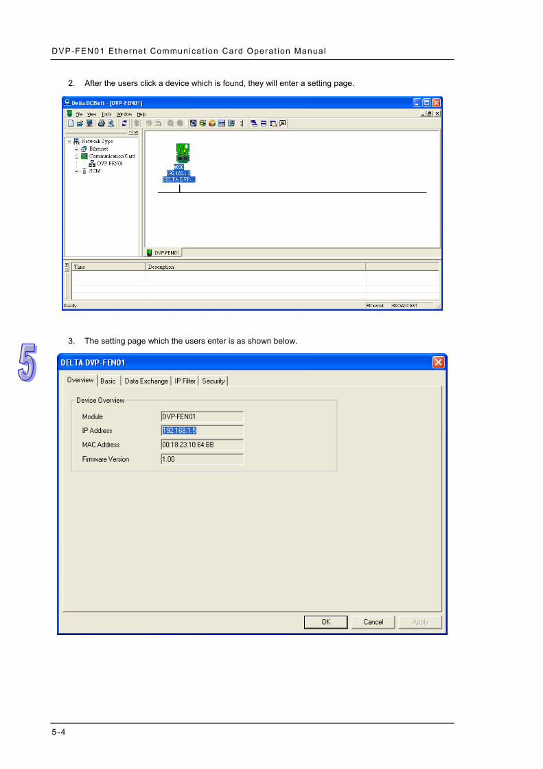
2. After the users click a device which is found, they will enter a setting page.
3. The setting page which the users enter is as shown below.
5-4

Chapter 5 Set t ing DVP-FEN01 by Means of Software
Searching for a specific model 1. Users have to right-click Ethernet on the left side of the Delta DCISoft window, and then click
Configure.
2. The users have to select the model (DVP-FEN01) for which they want to search in the Configure window. After they click OK, the DVP-FEN01 Ethernet communication card which is on a network will be searched for.
5-5

DVP-FEN01 Ethernet Communicat ion Card Operat ion Manual
3. The DVP-FEN01 Ethernet communication card which is found is displayed on the right side of the Delta DCISoft window.
Searching for a specific IP address
1. In the Communication Setting window, users have to select Ethernet in the Communication Type drop-down list box, type an IP address in the IP box, and click OK. The default IP address 255.255.255.255 is for a search by means of broadcasting.
5-6

Chapter 5 Set t ing DVP-FEN01 by Means of Software
2. After the users click IP Search on the toolbar, the IP address set will be searched for.
3. The DVP-FEN01 Ethernet communication card to which the IP address set is assigned, is displayed
on the right side of the Delta DCISoft window. After the users click DVP-FEN01, they will enter a setting page.
5-7

DVP-FEN01 Ethernet Communicat ion Card Operat ion Manual
Opening the setting page for DVP-FEN01 by means of RS-232 1. If users select RS232 in the Communication Type drop-down list box, they have to select a
communication port in the COM Port drop-down list box. If the users want to search for DVP-FEN01 by means of RS-232, they do not need to set communication parameters (a data length, a parity bit, the number of stop bits, and a transmission speed).
5-8

Chapter 5 Set t ing DVP-FEN01 by Means of Software
2. After the users click Search on the toolbar, they can search for DVP-FEN01 by means of RS-232.
Other settings are the same as searching for a specific IP address.
5-9

DVP-FEN01 Ethernet Communicat ion Card Operat ion Manual
5.2 Basic Settings
The setting of a module name, the setting of a network, and the setting of keepalive time are basic settings. Basic settings
1. Module name
There may be several DVP-FEN01 Ethernet communication cards on a network. In order to identify the DVP-FEN01 Ethernet communication cards, users can set name for the DVP-FEN01 Ethernet communication cards.
2. Setting a network (1) Assignment of an IP address
There are two ways to assign IP addresses. Static IP address: An IP address is set by users. DHCP: An IP address is automatically assigned by a server. There must be a server existing on a
local area network. Item Description
Static IP address Users assign an IP address, a subnet mask, and a default gateway.
DHCP A DHCP server is automatically requested to assign an IP address, a subnet mask, and a default gateway.
(2) IP address
An IP address is the address of a device on a network. Every device connected to a network needs an IP address. If a wrong IP address is used, the device can not connect to a network, and even other devices can not connect to the network. Please contact a network administrator to get more information about assigning an IP address. The default IP address of DVP-FEN01 is 192.168.1.5.
(3) Subnet mask A subnet mask is an important parameter for setting a subnet, and is used to judge whether the IP address of a destination device and the IP address of a local device are in the same subnet. If the IP address of a destination device and the IP address of a local device are not in the same subnet,
5-10
Chapter 5 Set t ing DVP-FEN01 by Means of Software
the local device will send a packet to a gateway, and the gateway will send the packet to another subnet. If the setting of a subnet is incorrect, a destination device can not communicate with DVP-FEN01 normally. Users can judge whether the IP address of a destination device and the IP address of a local device are in the same subnet by performing a bitwise AND operation between the IP address of the local device and the subnet mask, and a bitwise AND operation between the IP address of the destination device and the subnet mask. If the two values gotten are the same, the IP address of the destination device and the IP address of the local device are in the same subnet. The default subnet mask of DVP-FEN01 is 255.255.255.0.
(4) Default gateway A gateway is a network point that acts as an entrance to another network. For example, in order to connect a local area network and a wide area network, a gateway is needed. The IP address that a gateway uses and the IP address of DVP-FEN01 must be in the same subnet. The default gateway of DVP-FEN01 is 192.168.1.1.
3. Setting keepalive time Keepalive time is a TCP keepalive period. A second is a unit. The default keepalive time set for DVP-FEN01 is 30 seconds. After DVP-FEN01 and other devices are connected to a network, DVP-FEN01 will be automatically disconnected from the network to avoid too many connections if no network packet is sent during the period.
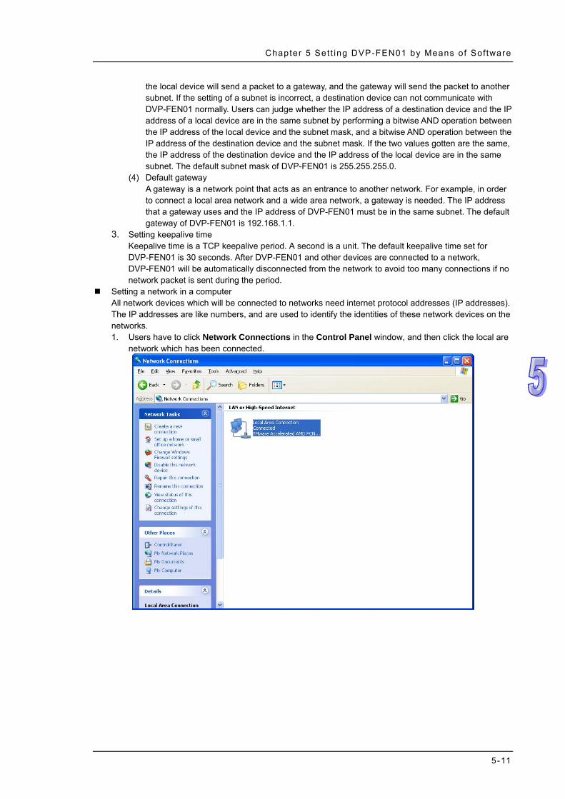
Setting a network in a computer All network devices which will be connected to networks need internet protocol addresses (IP addresses). The IP addresses are like numbers, and are used to identify the identities of these network devices on the networks. 1. Users have to click Network Connections in the Control Panel window, and then click the local are
network which has been connected.
5-11
DVP-FEN01 Ethernet Communicat ion Card Operat ion Manual
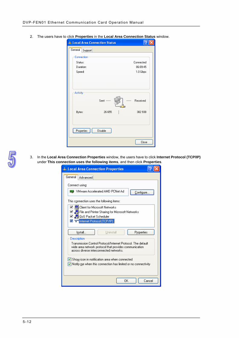
2. The users have to click Properties in the Local Area Connection Status window.
3. In the Local Area Connection Properties window, the users have to click Internet Protocol (TCP/IP)
under This connection uses the following items, and then click Properties.
5-12

Chapter 5 Set t ing DVP-FEN01 by Means of Software
4. The users have to type “192.168.1.6” in the IP address box in the Internet Protocol (TCP/IP) Properties window, and then click OK.
5-13

DVP-FEN01 Ethernet Communicat ion Card Operat ion Manual
5.3 Data Exchange
Users can set data exchange between DVP-FEN01 and slave stations by means of software. After the setting of data exchange is complete, the users can enable the data change directly without having to write a PLC program.
Setting data exchange 1. Enabling data exchange
Users can select or unselect the Enable Data Exchange checkbox. If the Enable Data Exchange checkbox is selected, the data set can be exchanged.
2. Condition of enabling data exchange Users can select Program Control, PLC Run, or Always Enable in the Enable Condition drop-down list box. If Program Control is selected, the data set will be exchanged according to a PLC program. (If the value in CR#13 is 2, data exchange will be executed. If the value in CR#13 is 0, the execution of data exchange will stop.) If PLC Run is selected, DVP-FEN01 will continuously execute data exchange after the RUN/STOP switch on a PLC is moved out of the STOP position and into the RUN position, and the execution of the data exchange will not stop until the RUN/STOP switch is moved out of the RUN position and into the STOP position. If Always Enable is selected, DVP-FEN01 will continuously execute data exchange until the setting in DCISoft is changed.
3. Slave ID and IP address Users have to type the IP addresses of Ethernet slaves. For example, if DVP-FEN01 exchange data with network equipment, the IP address of the network equipment is 192.168.1.1, and the slave ID of the network equipment is 1, the slave ID that the users have to type is 1, the IP address that the users have to type is 192.168.1.1.
4. Master device, slave device, and quantity ←: Start reception register in a master station←Start transmission register in a slave station →: Start transmission register in a master station→Start reception register in a slave station
5-14
Chapter 5 Set t ing DVP-FEN01 by Means of Software
When data exchange is executed, DVP-FEN01 write data to a slave station, and then read data from the slave station. Quantity: A slave station can send 100 pieces of data at most and receive 100 pieces of data at most simultaneously ※Please refer to manuals related to DVP-EH3 series PLCs for more information about the usage of
data registers. 5. Please refer to section 6.6~section 6.8 for more information.
5.4 IP Filter
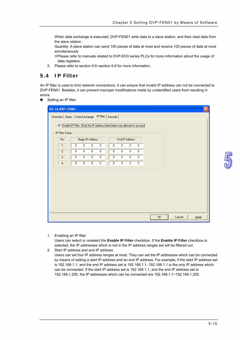
An IP filter is used to limit network connections. It can ensure that invalid IP address can not be connected to DVP-FEN01. Besides, it can prevent improper modifications made by unidentified users from resulting in errors. Setting an IP filter
1. Enabling an IP filter
Users can select or unselect the Enable IP Filter checkbox. If the Enable IP Filter checkbox is selected, the IP addresses which is not in the IP address ranges set will be filtered out.
2. Start IP address and end IP address Users can set four IP address ranges at most. They can set the IP addresses which can be connected by means of setting a start IP address and an end IP address. For example, if the start IP address set is 192.168.1.1, and the end IP address set is 192.168.1.1, 192.168.1.1 is the only IP address which can be connected. If the start IP address set is 192.168.1.1, and the end IP address set is 192.168.1.255, the IP addresses which can be connected are 192.168.1.1~192.168.1.255.
5-15

DVP-FEN01 Ethernet Communicat ion Card Operat ion Manual
5.5 Setting a Password
After users set DVP-FEN01, they can set a password to prevent the setting values in DVP-FEN01 from being changed improperly. Setting a password
1. Modifying a password
After users select the Modify checkbox, the can modify the password which has been set. 2. New password
Users can set a personal password. A password is composed of 4 characters at most. If the Password checkbox in the Password Setup section is left blank, DVP-FEN01 will not be protected by a password.
3. Confirming the password set Users have to type the password set again in the Confirm Password box.
4. Please refer to section 6.3 and section 6.4 for more information. Note: If users set a password, they have to type the password before they set DVP-FEN01.
5-16

Chapter 5 Set t ing DVP-FEN01 by Means of Software
5.6 Restoring DVP-FEN01 to Its Factory Settings
If users want to erase the settings in DVP-FEN01, they can select the Factory Setting checkbox. Restoring DVP-FEN01 to its factory settings
After users select the Factory Setting checkbox, and click Yes in the window which appears, DVP-FEN01 will be restored to its factory settings. Note: The RS-232 on DVP-FEN01 is used to restore DVP-FEN01 to its factory setting. Whether
DVP-FEN01 is protected by a password or not, DVP-FEN01 can be restored to its factory settings. It takes about 10 seconds to restore DVP-FEN01 to its factory settings, and therefore users should not switch off power during the period.
5-17

DVP-FEN01 Ethernet Communicat ion Card Operat ion Manual
5-18
MEMO
Chapter 6 Examples
Contents 6.1 Connecting WPLSoft to a DVP-EH3 Series PLC by Means of the Ethernet Port on
DVP-FEN01.......................................................................................................... 6-2 6.2 Connecting WPLSoft to a DVP-EH3 Series PLC by Means of the RS-232 Port on
DVP-FEN01.......................................................................................................... 6-5 6.3 Setting/Removing a Password ............................................................................. 6-8 6.4 Lost Password (Restoring DVP-FEN01 to Its Factory Settings by Means of RS-232)
........................................................................................................................... 6-12 6.5 Setting an IP Filter.............................................................................................. 6-15 6.6 Always Enabling Data Exchange ....................................................................... 6-17 6.7 Enabling Data Exchange by Means of a Program ............................................. 6-19 6.8 Enabling Data Exchange by Means of the RUN/STOP switch on a PLC........... 6-21 6.9 Application of ETHRW........................................................................................ 6-23
6-1

DVP-FEN01 Ethernet Communicat ion Card Operat ion Manual
6.1 Connecting WPLSoft to a DVP-EH3 Series PLC by Means of the Ethernet Port on DVP-FEN01
Function Downloading the program in WPLSoft, uploading the program in a PLC, or monitoring the program in a PLC by means of the Ethernet port on DVP-FEN01
Network environment
(1) The IP address of the computer on which WPLSoft runs is 192.168.1.33. (2) Subnet mask: 255.255.255.0; Gateway: 192.168.1.1 (3) The IP address of DVP-FEN01 is 192.168.1.5. (4) Using a cat 5e cable or a hub to connect the computer on which WPLSoft runs and
DVP-FEN01
1. Users have to click Communication Setting on the Options menu in WPLSoft.
6-2

Chapter 6 Examples
2. The users have to select Ethernet in the Type drop-down list box, and then click OK.
3. After Auto-Search Ethernet Module is clicked, all the DVP-FEN01 Ethernet communication cards on a
network will be searched for.
6-3

DVP-FEN01 Ethernet Communicat ion Card Operat ion Manual
4. The DVP-FEN01 Ethernet communication card found is listed on the left side of the Delta WPLSoft
window, and its IP address is 192.168.1.5. The users can download a program to the DVP-EH3 series PLC which is connected to WPLSoft, upload the program in the PLC, or monitor the PLC by means of the DVP-FEN01 Ethernet communication card.
5. After the users click DCISoft, they can set DVP-FEN01 further in DCISoft. Please refer to Chapter 5 for
more information.
6-4

Chapter 6 Examples
6.2 Connecting WPLSoft to a DVP-EH3 Series PLC by Means of the RS-232 Port on DVP-FEN01
Function Downloading the program in WPLSoft, uploading the program in a PLC, or monitoring the program in a PLC by means of the RS-232 port on DVP-FEN01
Network environment
Using DVPACAB2A30 to connect the computer on which WPLSoft runs and DVP-FEN01
1. Users have to click Communication Setting on the Options menu in WPLSoft.
6-5

DVP-FEN01 Ethernet Communicat ion Card Operat ion Manual
2. The users have to select Ethernet in the Type drop-down list box, select a communication port in the COM Port box, select 8 in the Data Length drop-down list box, select None in the Parity drop-down list box, select 1 in the Stop Bits drop-down list box, select 19200 in the Baud Rate drop-down list box, select the ASCII option button, and click OK. (DVP-FEN01 only supports a baud rate of 19200 bps, 8-bit data, none of parity bits, 1 stop bit, and Modbus ASCII.)
6-6

Chapter 6 Examples
3. RS232 on the left side of the Delta WPLSoft window is checked. The users can download a program to the DVP-EH3 series PLC which is connected to WPLSoft, upload the program in the PLC, or monitor the PLC by means of DVP-FEN01.
4. After the users click DCISoft, they can set DVP-FEN01 further in DCISoft. Please refer to Chapter 5 for more information.
6-7
DVP-FEN01 Ethernet Communicat ion Card Operat ion Manual
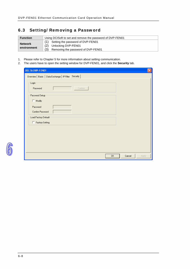
6.3 Setting/Removing a Password
Function Using DCISoft to set and remove the password of DVP-FEN01
Network environment
(1) Setting the password of DVP-FEN01 (2) Unlocking DVP-FEN01 (3) Removing the password of DVP-FEN01
1. Please refer to Chapter 5 for more information about setting communication. 2. The users have to open the setting window for DVP-FEN01, and click the Security tab.
6-8

Chapter 6 Examples
3. The users have to select the Modify checkbox, type “1234” in the Password box and the Confirm Password box, and click OK.
6-9

DVP-FEN01 Ethernet Communicat ion Card Operat ion Manual
4. The users have to reopen the setting window for DVP-FEN01. Owing to the fact DVP-FEN01 is protected by the password set, DVP-FEN01 can not be set. The users have to type the password set in the Password box, and click OK.
5. After the users type the password set, DVP-FEN01 will be unlocked temporarily, and they can modify parameters. If the users close the setting window for DVP-FEN01, DVP-FEN01 will be automatically locked again.
6-10
Chapter 6 Examples
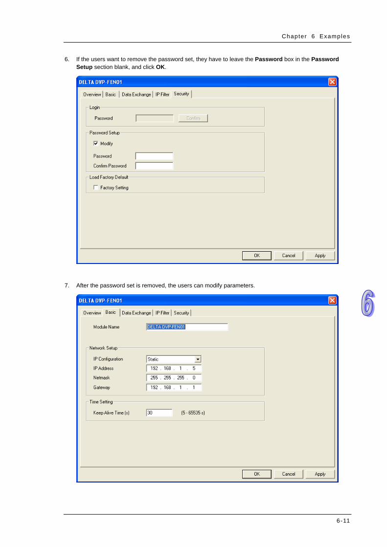
6. If the users want to remove the password set, they have to leave the Password box in the Password Setup section blank, and click OK.
7. After the password set is removed, the users can modify parameters.
6-11

DVP-FEN01 Ethernet Communicat ion Card Operat ion Manual
6.4 Lost Password (Restoring DVP-FEN01 to Its Factory Settings by Means of RS-232)
Function Restoring DVP-FEN01 to Its Factory Settings by Means of RS-232
Network environment
(1) Setting the password of DVP-FEN01 (2) If users forget the password of DVP-FEN01, they can restore DVP-FEN01 to its
factory settings by means of RS-232.
1. After users use DVPACAB2A30 to connect the computer on which DCISoft runs and DVP-FEN01, they have to click the Security tab.
6-12

Chapter 6 Examples
2. After the users select the Factory Setting checkbox, a window will appear. After the users click Yes in the window, DVP-FEN01 will be restored to its factory settings, and the password set will be removed. (It takes about 5~10 seconds to restore DVP-FEN01 to its factory settings.)
3. After DVP-FEN01 is searched for again, it will be restored to its factory settings.
6-13

DVP-FEN01 Ethernet Communicat ion Card Operat ion Manual
6-14

Chapter 6 Examples
6.5 Setting an IP Filter
Function Setting an IP filter Network environment
(1) The IP address of DVP-FEN01 is 192.168.1.5. (2) Only 192.168.1.33 and 172.16.1.1~172.16.1.255 are allowed to be connected.
1. Please refer to Chapter 5 fore more information about setting communication. 2. Users have to click the IP Filter tab in the setting window for DVP-FEN01.
6-15

DVP-FEN01 Ethernet Communicat ion Card Operat ion Manual
3. The users have to select the Enable IP Filter checkbox, type the first start address “192.168.1.33”, and type the first end address “192.168.1.33”.
4. The users have to type the second start address “172.16.1.1”, type the second end address “172.16.1.255”, and click Apply. Only the equipment whose IP address is in the range of 172.16.1.1 to 172.16.1.255 can be connected to DVP-FEN01.
6-16

Chapter 6 Examples
6.6 Always Enabling Data Exchange
Function
Data exchange is always enabled. A timer is set. After the timer set is enabled, the value in the timer will be written to D0~D99 in PLC A. The values in D0~D99 in PLC A are written to D0~D99 in PLC B, and the values in D0~D99 in PLC B are written to D200~D299 in PLC A.
Network environment
(1) Using a static IP address (2) IP address of PLC A: 192.168.1.5 (3) IP address of PLC B: 192.168.1.6 (4) PLC A exchange data with PLC B.
1. Please refer to Chapter 5 for more information about setting communication. 2. Users have to open the setting window for PLC A, and click the Data Exchange tab.
6-17

DVP-FEN01 Ethernet Communicat ion Card Operat ion Manual
3. The users have to select the Enable Data Exchange checkbox, and select Always Enable in the Enable Condition drop-down list box. They have to enable data exchange 1, and type the first IP address “192.168.1.6”. Besides, they have to select D200 as the start reception register in PLC A, select D0 as the start transmission register in the PLC B, select D0 as the start transmission register in PLC A, and select D0 as the start reception register in PLC B. The number of values which will be sent by PLC B is 100, and the number of values which will be sent by PLC A is 100. After the users click Apply, the data exchange set will be enabled.
4. After PLC A is set, the users have to write the program shown below, and download the program to PLC A. (1) When PLC A runs, and M20 is turned ON, the value in T0 is written to D0~D99 in PLC A. (2) The values in D0~D99 in PLC A are written to D0~D99 in PLC B. (3) The values in D0~D99 in PLC B are written to D200~D299 in PLC A. (4) When PLC A stops, the data exchange set is still executed, but the ladder diagram in PLC A is not
executed.
6-18

Chapter 6 Examples
6.7 Enabling Data Exchange by Means of a Program
Function
Data exchange is enabled by a program. A timer is set. After the timer set is enabled, the value in the timer will be written to D0~D99 in PLC A. The values in D0~D99 in PLC A are written to D0~D99 in PLC B, and the values in D0~D99 in PLC B are written to D200~D299 in PLC A.
Network environment
(1) Using a static IP address (2) IP address of PLC A: 192.168.1.5 (3) IP address of PLC B: 192.168.1.6 (4) PLC A exchange data with PLC B.
1. Please refer to Chapter 5 for more information about setting communication. 2. Users have to open the setting window for PLC A, and click the Data Exchange tab.
6-19
DVP-FEN01 Ethernet Communicat ion Card Operat ion Manual
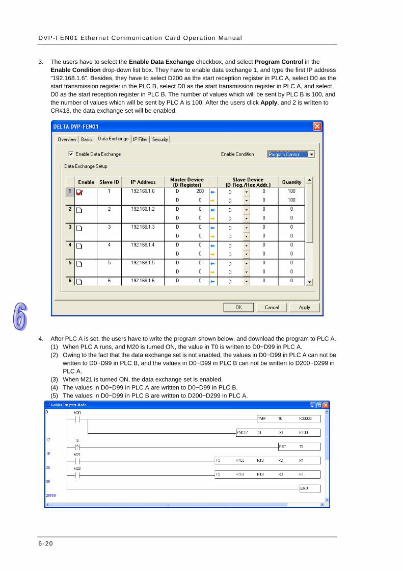
3. The users have to select the Enable Data Exchange checkbox, and select Program Control in the Enable Condition drop-down list box. They have to enable data exchange 1, and type the first IP address “192.168.1.6”. Besides, they have to select D200 as the start reception register in PLC A, select D0 as the start transmission register in the PLC B, select D0 as the start transmission register in PLC A, and select D0 as the start reception register in PLC B. The number of values which will be sent by PLC B is 100, and the number of values which will be sent by PLC A is 100. After the users click Apply, and 2 is written to CR#13, the data exchange set will be enabled.
4. After PLC A is set, the users have to write the program shown below, and download the program to PLC A. (1) When PLC A runs, and M20 is turned ON, the value in T0 is written to D0~D99 in PLC A. (2) Owing to the fact that the data exchange set is not enabled, the values in D0~D99 in PLC A can not be
written to D0~D99 in PLC B, and the values in D0~D99 in PLC B can not be written to D200~D299 in PLC A.
(3) When M21 is turned ON, the data exchange set is enabled. (4) The values in D0~D99 in PLC A are written to D0~D99 in PLC B. (5) The values in D0~D99 in PLC B are written to D200~D299 in PLC A.
6-20

Chapter 6 Examples
6.8 Enabling Data Exchange by Means of the RUN/STOP switch on a PLC
Function
Data exchange is enabled by the RUN/STOP switch on PLC A. A timer is set. After the timer set is enabled, the value in the timer will be written to D0~D99 in PLC A. The values in D0~D99 in PLC A are written to D0~D99 in PLC B, and the values in D0~D99 in PLC B are written to D200~D299 in PLC A.
Network environment
(1) Using a static IP address (2) IP address of PLC A: 192.168.1.5 (3) IP address of PLC B: 192.168.1.6 (4) PLC A exchange data with PLC B.
1. Please refer to Chapter 5 for more information about setting communication. 2. Users have to open the setting window for PLC A, and click the Data Exchange tab.
6-21

DVP-FEN01 Ethernet Communicat ion Card Operat ion Manual
3. The users have to select the Enable Data Exchange checkbox, and select PLC Run in the Enable Condition drop-down list box. They have to enable data exchange 1, and type the first IP address “192.168.1.6”. Besides, they have to select D200 as the start reception register in PLC A, select D0 as the start transmission register in the PLC B, select D0 as the start transmission register in PLC A, and select D0 as the start reception register in PLC B. The number of values which will be sent by PLC B is 100, and the number of values which will be sent by PLC A is 100. After the users click Apply, the data exchange set will not be executed if PLC A stops, and the data exchange set will be executed if PLC A runs.
4. After PLC A is set, the users have to write the program shown below, and download the program to PLC A. (1) When PLC A runs, and M20 is turned ON, the value in T0 is written to D0~D99 in PLC A. (2) The values in D0~D99 in PLC A are written to D0~D99 in PLC B. (3) The values in D0~D99 in PLC B are written to D200~D299 in PLC A. (4) When PLC A stops, the data exchange set is not executed, and the ladder diagram in PLC A is not
executed.
6-22

Chapter 6 Examples
6.9 Application of ETHRW
Function PLC A sends a Modbus command, and requests the timer value stored in D10 (H’100A) in PLC B. The reply that PLC B makes is stored in D100 in PLC A.
Network environment
(1) Using a static IP address (2) IP address of PLC A: 192.168.1.5 (3) IP address of PLC B: 192.168.1.6 (4) Using ETHRW to write a Modbus TCP command (5) PLC A requests the timer value stored in D10 (H’100A) in PLC B every second, and
the reply that PLC B makes is stored in D100 in PLC A.
1. Please refer to Chapter 5 for more information about setting communication. 2. Users have to write the program shown below, and download the program to PLC A.
Using ETHRW: ETHRW D0 H100A D10 K1
3. The users have to write the program shown below, and download the program to PLC B.
4. When PLC A and PLC B run, (1) T0 in PLC B begins to count, and the value in T0 is moved to D10 (H’100A) in PLC B. (2) PLC A sends the data set by M1002 by means of the Modbus TCP command sent by M1013 every
second to request the timer value stored in D10 (H’100A) in PLC B. (3) the replay that PLC B makes is stored in D100 in PLC A. (4) the value in D100 in PLC A is the value in D10 in PLC B which is updated every second.
6-23

DVP-FEN01 Ethernet Communicat ion Card Operat ion Manual
6-24
MEMO