fema 403 -- chapter 3
TRANSCRIPT
William Baker
3WTC 3 3.1 Design and Construction Features
WTC 3 (also known as the World Trade Center Hotel, the Vista Hotel, and the Marriott Hotel) was almost completely destroyed as a result of the September 11 attacks due to debris from the collapse of the adjacent WTC 1 and WTC 2. This chapter describes the structural design and construction features of the building as well as details of its collapse. The information contained in this section is based on architectural and structural design drawings dating to 1978, photographs, written reports and articles, videotape recordings, and interviews with Marriott staff. Steel shop drawings were not available for review.
3.1.1 Project Overview WTC 3 was a steel-framed hotel building located on the southwest corner of the WTC Complex
immediately to the south of WTC 1 (the north tower) and to the west of WTC 2 (the south tower). The site was bounded on the west by West Street and on the south by Liberty Street. The building was designed in 1978/1979 by Skidmore, Owings & Merrill (SOM), architects; Weiskopf & Pickworth, structural engineers; and Jaros, Baum & Bolles, mechanical engineers. Weiskopf & Pickworth designed the superstructure for the hotel. Skilling, Helle, Christiansen, and Robertson designed the transfer system between the hotel column grid and the below grade parking grid as well as the structure below the transfer system. WTC 3 opened in 1981 and housed the 825-room Vista hotel. The original owner and operator of the hotel was Hilton International, but the property was sold in 1996 to Marriott Hotels (Harris 2001). Marriott operated the hotel from 1996 until the attacks on September 11, 2001.
3.1.2 Building Description The building had 22 stories above grade and 6 stories below grade (labeled B1 through B6.) The roof
parapet line was approximately 242 feet above West Street. The north and west elevations are shown in Figure 3-1 and the south and east elevations are shown in Figure 3-2, as taken from the original architectural drawings from SOM. The first level below grade provided loading docks, building services, and other functions for the hotel. The other levels below grade were part of the overall WTC complex and provided parking space. The ground level housed the hotel lobby and ballroom. The two stories above the ground level lobby were occupied by restaurants and conference facilities. The next 18 stories accommodated the approximately 825 guest suites. A health club and mechanical services were located on the top floor of the building.
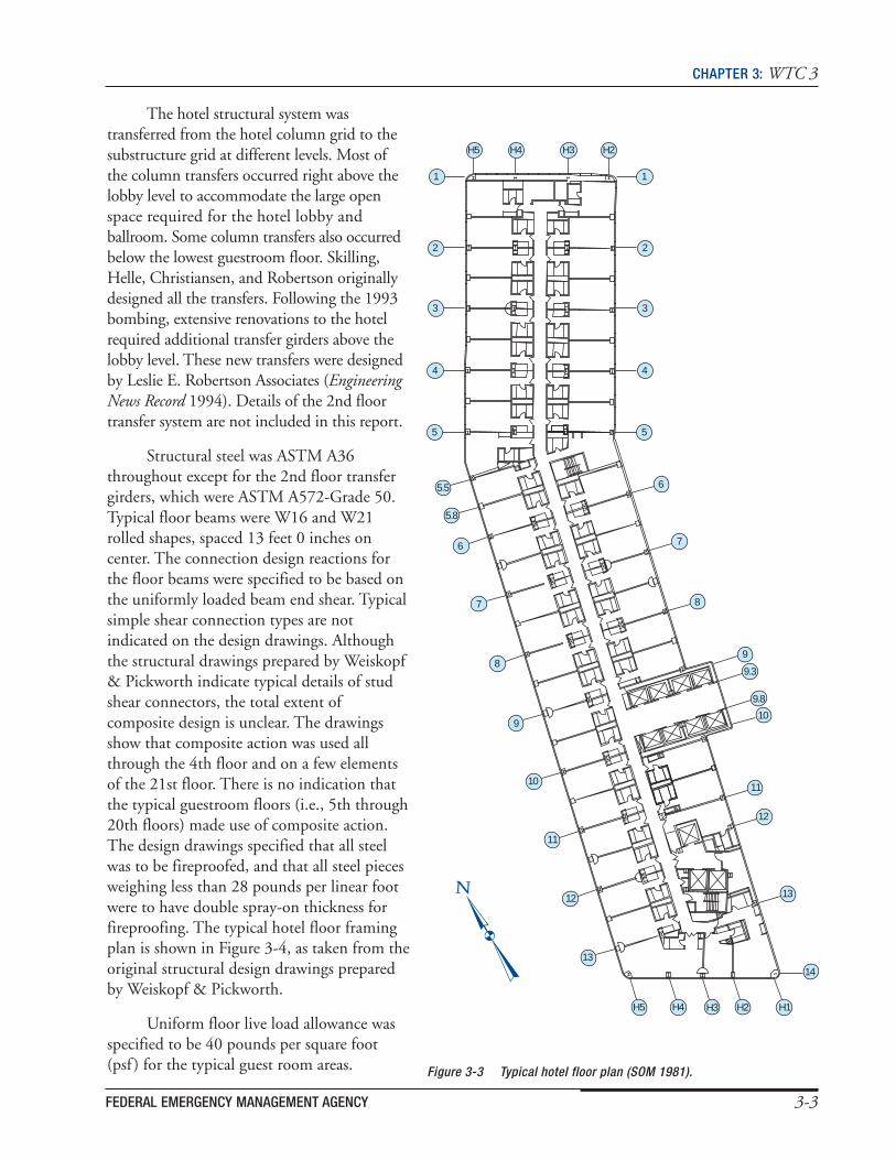
The building was a long rectangle in plan with an obtuse angle change at approximately one-third of the length of the building from the north. The typical floor of the building was approximately 64 feet wide and 330 feet long, with floor story heights of 9 feet 6 inches. Elevators were located at the east side of the building, roughly centered north to south, directly opposite the building entry, which was located on the west side of the building. The general arrangement of the hotel suites is indicated in Figure 3-3.
FEDERAL EMERGENCY MANAGEMENT AGENCY 3-1

CHAPTER 3: WTC 3
North Elevation (Developed) West Elevation (Developed)
Figure 3-1 Developed north and west elevations (SOM 1979).
South Elevation (Developed) East Elevation (Developed)
Figure 3-2 Developed south and east elevations (SOM 1979).
3.1.3 Structural Description The primary structural frame of WTC 3 was composed of rolled, wide-flange structural steel columns,
floor beams, and girders. The column grid for the building consisted of approximately twelve 26-foot-wide bays in the north-south direction with non-typical bays at the south end of the building and at the location of the plan angle change. In the east-west direction, there were three bays with column spacings of 18 feet 9-7/8 inches, 22 feet 6 inches, and 18 feet 9-3/4 inches. Steel columns were standard wide-flange W14-series shapes throughout (up to W14x500 at the 2nd floor). Details of column splices were not indicated on the structural design drawings.
3-2 WORLD TRADE CENTER BUILDING PERFORMANCE STUDY
CHAPTER 3: WTC 3
The hotel structural system was transferred from the hotel column grid to the substructure grid at different levels. Most of the column transfers occurred right above the lobby level to accommodate the large open space required for the hotel lobby and ballroom. Some column transfers also occurred below the lowest guestroom floor. Skilling, Helle, Christiansen, and Robertson originally designed all the transfers. Following the 1993 bombing, extensive renovations to the hotel required additional transfer girders above the lobby level. These new transfers were designed by Leslie E. Robertson Associates (Engineering News Record 1994). Details of the 2nd floor transfer system are not included in this report.
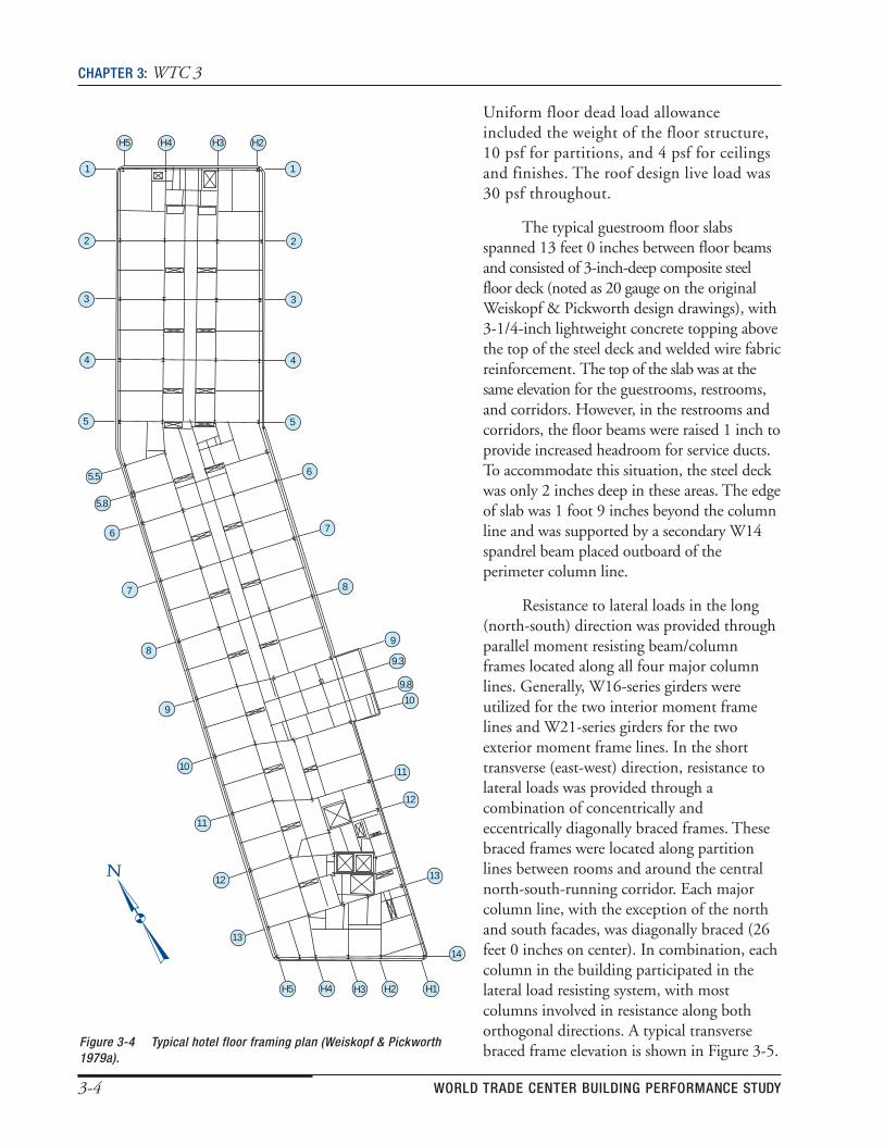
Structural steel was ASTM A36 throughout except for the 2nd floor transfer girders, which were ASTM A572-Grade 50. Typical floor beams were W16 and W21 rolled shapes, spaced 13 feet 0 inches on center. The connection design reactions for the floor beams were specified to be based on the uniformly loaded beam end shear. Typical simple shear connection types are not indicated on the design drawings. Although the structural drawings prepared by Weiskopf & Pickworth indicate typical details of stud shear connectors, the total extent of composite design is unclear. The drawings show that composite action was used all through the 4th floor and on a few elements of the 21st floor. There is no indication that the typical guestroom floors (i.e., 5th through 20th floors) made use of composite action. The design drawings specified that all steel was to be fireproofed, and that all steel pieces weighing less than 28 pounds per linear foot were to have double spray-on thickness for fireproofing. The typical hotel floor framing plan is shown in Figure 3-4, as taken from the original structural design drawings prepared by Weiskopf & Pickworth.
Uniform floor live load allowance was specified to be 40 pounds per square foot (psf ) for the typical guest room areas. Figure 3-3 Typical hotel floor plan (SOM 1981).
9.3
9.8
10
11
12
13
14
H2 H1H3H4H5
11
10
9
8
7
6
5.5
5.8
5
4
3
2
1
5
4
3
2
1
12
13
9
8
7
6
H5 H4 H3 H2
FEDERAL EMERGENCY MANAGEMENT AGENCY 3-3
CHAPTER 3: WTC 3
Uniform floor dead load allowance included the weight of the floor structure, 10 psf for partitions, and 4 psf for ceilings and finishes. The roof design live load was 30 psf throughout.
9.3
9.8
10
11
12
13
14
H2 H1 H3 H4 H5
11
10
9
8
7
6
5.5
5.8
5
4
3
2
1
5
4
3
2
1
12
13
9
8
7
6
H5 H4 H3 H2
The typical guestroom floor slabs spanned 13 feet 0 inches between floor beams and consisted of 3-inch-deep composite steel floor deck (noted as 20 gauge on the original Weiskopf & Pickworth design drawings), with 3-1/4-inch lightweight concrete topping above the top of the steel deck and welded wire fabric reinforcement. The top of the slab was at the same elevation for the guestrooms, restrooms, and corridors. However, in the restrooms and corridors, the floor beams were raised 1 inch to provide increased headroom for service ducts. To accommodate this situation, the steel deck was only 2 inches deep in these areas. The edge of slab was 1 foot 9 inches beyond the column line and was supported by a secondary W14 spandrel beam placed outboard of the perimeter column line.
Resistance to lateral loads in the long (north-south) direction was provided through parallel moment resisting beam/column frames located along all four major column lines. Generally, W16-series girders were utilized for the two interior moment frame lines and W21-series girders for the two exterior moment frame lines. In the short transverse (east-west) direction, resistance to lateral loads was provided through a combination of concentrically and eccentrically diagonally braced frames. These braced frames were located along partition lines between rooms and around the central north-south-running corridor. Each major column line, with the exception of the north and south facades, was diagonally braced (26 feet 0 inches on center). In combination, each column in the building participated in the lateral load resisting system, with most columns involved in resistance along both orthogonal directions. A typical transverse
Figure 3-4 Typical hotel floor framing plan (Weiskopf & Pickworth braced frame elevation is shown in Figure 3-5.1979a).
3-4 WORLD TRADE CENTER BUILDING PERFORMANCE STUDY

CHAPTER 3: WTC 3
3.2 1993 Attack WTC 3 was damaged in the February 26,
1993, bombing of the WTC. The bomb was set off in the second basement level parking garage under the north end of the hotel, adjacent to WTC 1. The explosion caused a major collapse of the slab at level B2 (approximately 130 feet by 130 feet in dimension) and a major, but smaller, slab collapse at Level B1 (approximately 50 feet by 80 feet). The West Street level (Concourse level) had a limited collapse (approximately 18 feet by 22 feet). Level 1 (Plaza level) was not ruptured, but had an area (10 feet by 10 feet) that was deflected upward. (The above data were taken from Isner and Klem [1994]). There were no slabs at levels B3 and B4 directly below the blast, and the debris landed on level B5. There was also significant damage to non-loadbearing partition walls and mechanical equipment. The damage was subsequently repaired. The bombing has been more extensively described in several reports, including those by Isner and Klem (1994) and the U.S. Fire Administration (1993).
3.3 2001 Attacks
3.3.1 Fire and Evacuation The following account was developed
through interviews with Marriott Hotel staff.
Small fires on the top floor were ignited as a result of projectiles through the roof, most likely after the impact of the aircraft with WTC 1. At least one of these fires was located in the health club on the top floor. Some jet fuel was reportedly involved in these fires.
Evacuation of the hotel guests and staff was initiated shortly after ignition of the fires. Building occupants were initially directed to the hotel lobby. Later, the building occupants were instructed to evacuate the building. It is unknown whether the fire alarm system was activated in the building. Hotel staff and fire service personnel alerted other building occupants while moving in the corridors on the guest room floors.
Roof
H5 H4 H3 H2
22nd Floor Mec
hani
cal
Gue
st R
oom
s M
eetin
g R
oom
s
21st Floor
20th Floor
19th Floor
18th Floor
17th Floor
16th Floor
15th Floor
14th Floor
13th Floor
12th Floor
11th Floor
10th Floor
9th Floor
8th Floor
7th Floor
6th Floor
5th Floor
4th Floor
3rd Floor
2nd Floor
LobbyAll of the building occupants were evacuated Below
from the building. However, two members of the Figure 3-5 Typical transverse bracing elevationhotel management team had each re-entered the (Weiskopf & Pickworth 1979b).
FEDERAL EMERGENCY MANAGEMENT AGENCY 3-5
CHAPTER 3: WTC 3
building to check on the safety of guests and firefighters, and incurred fatal injuries on the guest room floors upon collapse of WTC 2.
3.3.2 Building Response The response of WTC 3 to the September 11 events is complex and noteworthy. WTC 3 was
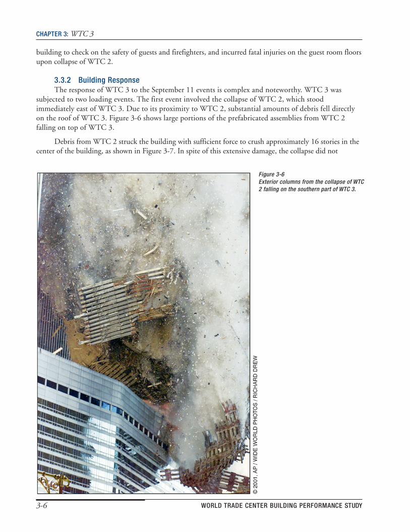
subjected to two loading events. The first event involved the collapse of WTC 2, which stood immediately east of WTC 3. Due to its proximity to WTC 2, substantial amounts of debris fell directly on the roof of WTC 3. Figure 3-6 shows large portions of the prefabricated assemblies from WTC 2 falling on top of WTC 3.
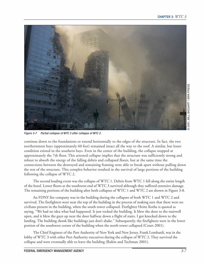
Debris from WTC 2 struck the building with sufficient force to crush approximately 16 stories in the center of the building, as shown in Figure 3-7. In spite of this extensive damage, the collapse did not
Figure 3-6Exterior columns from the collapse of WTC2 falling on the southern part of WTC 3.
3-6 WORLD TRADE CENTER BUILDING PERFORMANCE STUDY
CHAPTER 3: WTC 3
Figure 3-7 Partial collapse of WTC 3 after collapse of WTC 2.
continue down to the foundations or extend horizontally to the edges of the structure. In fact, the two northernmost bays (approximately 60 feet) remained intact all the way to the roof. A similar, but lesser condition existed in the southern bays. Even in the center of the building, the collapse stopped at approximately the 7th floor. This arrested collapse implies that the structure was sufficiently strong and robust to absorb the energy of the falling debris and collapsed floors, but at the same time the connections between the destroyed and remaining framing were able to break apart without pulling down the rest of the structure. This complex behavior resulted in the survival of large portions of the building following the collapse of WTC 2.
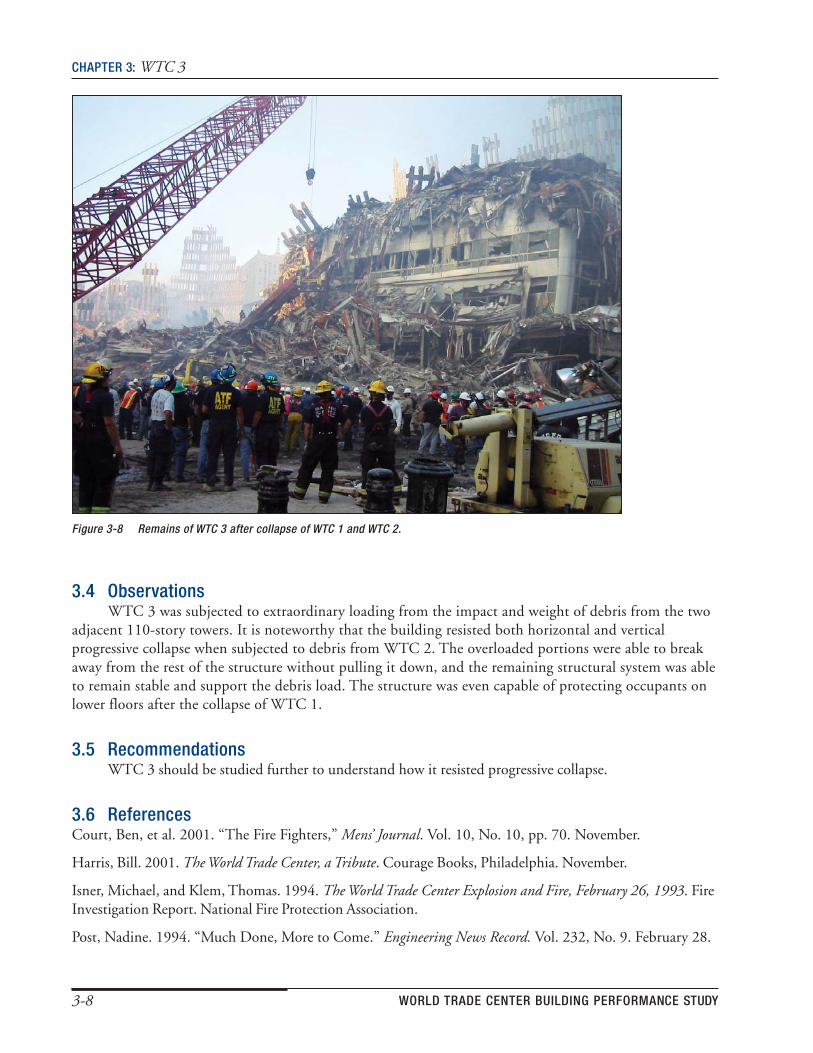
The second loading event was the collapse of WTC 1. Debris from WTC 1 fell along the entire length of the hotel. Lower floors at the southwest end of WTC 3 survived although they suffered extensive damage. The remaining portions of the building after both collapses of WTC 1 and WTC 2 are shown in Figure 3-8.
An FDNY fire company was in the building during the collapses of both WTC 1 and WTC 2 and survived. The firefighters were near the top of the building in the process of making sure that there were no civilians present in the building, when the south tower collapsed. Firefighter Heinz Kothe is quoted as saying, “We had no idea what had happened. It just rocked the building. It blew the door to the stairwell open, and it blew the guys up near the door halfway down a flight of stairs. I got knocked down to the landing. The building shook like buildings just don’t shake.” Subsequently, the firefighters were in the lower portion of the southwest corner of the building when the north tower collapsed (Court 2001).
The Chief Engineer of the Port Authority of New York and New Jersey, Frank Lombardi, was in the lobby of WTC 3 with other Port Authority executives during the collapse of WTC 2. They survived the collapse and were eventually able to leave the building (Rubin and Tuchman 2001).
FEDERAL EMERGENCY MANAGEMENT AGENCY 3-7
CHAPTER 3: WTC 3
Figure 3-8 Remains of WTC 3 after collapse of WTC 1 and WTC 2.
3.4 Observations WTC 3 was subjected to extraordinary loading from the impact and weight of debris from the two
adjacent 110-story towers. It is noteworthy that the building resisted both horizontal and vertical progressive collapse when subjected to debris from WTC 2. The overloaded portions were able to break away from the rest of the structure without pulling it down, and the remaining structural system was able to remain stable and support the debris load. The structure was even capable of protecting occupants on lower floors after the collapse of WTC 1.
3.5 Recommendations WTC 3 should be studied further to understand how it resisted progressive collapse.
3.6 ReferencesCourt, Ben, et al. 2001. “The Fire Fighters,” Mens’ Journal. Vol. 10, No. 10, pp. 70. November.
Harris, Bill. 2001. The World Trade Center, a Tribute. Courage Books, Philadelphia. November.
Isner, Michael, and Klem, Thomas. 1994. The World Trade Center Explosion and Fire, February 26, 1993. FireInvestigation Report. National Fire Protection Association.
Post, Nadine. 1994. “Much Done, More to Come.” Engineering News Record. Vol. 232, No. 9. February 28.
3-8 WORLD TRADE CENTER BUILDING PERFORMANCE STUDY
CHAPTER 3: WTC 3
Rubin, D., and Tuchman, J. 2001. “WTC Engineers Credit Design in Saving Thousands of Lives.” Engineering News Record. Vol. 247, No. 16, pp. 12. October 15.
Skidmore, Owings and Merrill, LLP. 1979a. Drawing A-11, WTC Hotel. New York, NY.
Skidmore, Owings and Merrill, LLP. 1979b. Drawing A-12, WTC Hotel. New York, NY.
Skidmore, Owings and Merrill, LLP. 1981. Drawing A-6C. New York, NY.
United States Fire Administration. 1993. The World Trade Center Bombing: Report and Analysis. Technical Reports Series. Prepared in association with the Federal Emergency Management Agency. October.
Weiskopf &Pickworth. 1979a. Drawing S-5. New York, NY.
Weiskopf &Pickworth. 1979b. Drawing S-11. New York, NY.
FEDERAL EMERGENCY MANAGEMENT AGENCY 3-9