feeders and mixers for flour fortification: a guide for
TRANSCRIPT

FEEDERS AND MIXERS FOR FLOUR
FORTIFICATION
A GUIDE FOR SELECTION, INSTALLATION AND PROCUREMENT
QUENTIN JOHNSON
February 2005
Table of Contents
INTRODUCTION ......................................................Error! Bookmark not defined. SECTION I: ................................................................................................................. 4 1. Principles and Practical Aspects for the use of feeders............................................ 4 2. Feeders and Mixers for Flour Fortification in Continuous Systems ........................ 7 3. Fortification systems for different size mills.......................................................... 11 4. Additional Requirements........................................................................................ 14 SECTION II. Procurement of Feeders and Mixers.................................................... 15 SECTION III. Technology Transfer.......................................................................... 20 ANNEX I: FEEDER INSTALLATION COSTS ...................................................... 23 ANNEX II: DIAGRAMS AND PHOTOGRAPHS................................................... 24
- 1 -

2

FOREWORD
As many as a third of the world’s people are affected by vitamin and mineral deficiency – the lack of small amount of essential nutrients like iron, folic acid, zinc and vitamin A in their diets. Such deficiency inflicts a heavy toll on virtually every developing country. Vitamin and mineral deficiency causes the deaths of more than one million young children and close to a quarter of a million severe birth defects every year. National economies lose as much as 2% of the gross domestic product every year as a result of vitamin and mineral deficiency.
The cheapest and most sustainable way to control this problem is to add vitamins and minerals to staple foods. In many countries, governments and millers have come together to develop strategies, protocols and standards for fortifying staple foods with vitamins and minerals and a growing number of food producers throughout the world are now fortifying a wide variety of staple foods.
Flour millers have a particularly good opportunity to join the global effort to eliminate vitamin and mineral deficiency and to truly become champions in their communities. The cost is miniscule, but the benefit is huge. Indeed, millers in many countries have expressed commitment to fortifying flour with essential vitamins and minerals. They consider it their contribution to their nations’ health and wellbeing. However, many millers also identified a need for guidance in the selection of the right type of feeders suitable for their mills.
With this manual we aim to provide an overview of the types of feeders and mixers normally used for flour fortification. This manual also provides an overview of the main considerations to be taken into account in selecting, installing and using feeders and mixers for mills commonly found in developing countries. Some low cost options for feeders and mixers for different country and regional situations are also presented.
M.G. Venkatesh Mannar
President, The Micronutrient Initiative February 2005
3
SECTION I:
Design and Specifications for Feeders and Mixers
This section covers the design and specifications for feeders and mixers for use in flour fortification in large-scale mills. Large scale mills are considered:
- To have rated milling capacities equal to or greater than 24MT per 24 hours (based on grain processing).
- To have an integrated system of milling machines and sifters connected by conveyors and or blowlines.
In particular this section covers:
1. The Principle of Feeder Accuracy for feeders used in flour fortification programs.
2. The types of feeders and mixers (both batch type and continuous type) that are suitable for the milling systems commonly used in sub-Saharan Africa; Latin America; Middle East and North Africa; and South Asia.
3. Identification of possible options of feeders and mixers (with pictures where applicable) based on different types of mills, mill capacities and flour production rates; and recommendation of the critical points to consider while deciding among the options.
4. Identification of situations where additional equipment like conveyors may be required.
1. Principles and Practical Aspects for the use of feeders.
There are different types of feeders manufactured by several companies around the world that are in common use today. These feeders are being used to add both micronutrient premixes as well as other ingredients such as flour additives and baking agents.
Even though there are different types of feeders the most important issue affecting the design and selection of feeders is Feeder Accuracy. There are three important factors that taken together define Feeder Accuracy. These are:
- Repeatability
Repeatability is defined as how consistent the feeder discharge rate is at a given operating point.
- Linearity
Linearity is defined as the accuracy of the feeder discharge at the determined feed rate over its full operating range.
4

- Stability
Stability is defined as the degree of drift in performance of the feeder over a period of time.
These three aspects of feeder operation and performance need to be addressed when it comes to assessing feeder accuracy. In addition these aspects must be considered when establishing operational process and quality control practices in the flour mill.
Repeatability
Repeatability or feeder precision is the most common performance parameter used by feeder users. Repeatability is critical to quality control and quality assurance because it can be used to determine the expected variability of the discharge stream and therefore the final product (fortified flour.)
Measurement of Repeatability
Repeatability is measured by taking a series of timed samples from the discharge stream, weighing them and then calculating the standard deviation (+SD) of the sample weights calculated as a percentage of the mean or average of the samples taken.
Sample size
A minimum of 30 samples at a chosen discharge rate is required to determine the average and SD. Statistical references indicate that 30 samples is sufficient to represent the total population in a normal distribution.
Operating Range Sampling
Normally this is carried out at the nominal or intended operating rate of the feeder. If the feeder is intended for use over a range of operating rates then the repeatability test must be carried out at each point over the range.
Expression of Repeatability
Normally repeatability is expressed as 2 Standard Deviations. At this level 95.5% of samples will fall within + 2 SD.
For example if the sampling shows a SD of + 0.4% then 95.5% of the samples will fall within + 0.8%
The repeatability expression will contain:
- a + percentage error value (the Sigma or SD level) and;
- the sampling criteria.
5
Linearity
Repeatability does not indicate any information about the feeder delivering the targeted rate. Repeatability only measures the variability of flow rate.
Linearity is the indicating measurement of how well the feeder delivers the desired rate throughout the feeders operating range. A straight-line correspondence between the set point on the feeder control and the actual average feed rate from the lowest operating control to the full scale operating point (maximum discharge) show perfect linearity.
Determination of Linearity Measurement
Several groups of timed catch samples should be taken from the feeder discharge stream. Normally 10 consecutive timed catch samples should be taken and weighed at each of the following flow rate settings:
5%, 25%, 50%, 75% and 100% of the full scale.
The lowest flow rate tested should be at the lowest operating point on the scale at which the feeder actually discharges.
The average sample weight is calculated for each of the 5 sets and the difference between the computed average and desired average weight is determined. The difference is known as the weight error and it can be expressed as a percentage of the desired rate at each setting.
Expression of Linearity
Linearity performance is expressed as:
A + percentage error value based on the set rate, the sampling criteria and the range from lowest setting to full scale setting.
Stability
Stability in the performance of a feeder is critical over the expected life of the equipment. The performance of a feeder can drift over time. That is, the amount that is delivered by the feeder may change over time. The following factors will contribute to the drift in performance:
- Type of feeder
- Control system stability (electronic or analogue control)
- Handling characteristics of the material being fed
- Variability of the material being fed
6
- The feeder’s mechanical system
- Maintenance program
- Operating environment
Drift can be detected by carrying out calibration checks using the timed weigh check method listed above under Repeatability. The calibration check can then be used to make adjustments to the feeder settings.
Millers will determine the appropriate frequency of calibration checks based on operation experience and the quality control and quality assurance program in place.
It must be stated that if a stable, drift free feeder is used then considerable ongoing cost savings in maintenance, off-specification product and potential processing downtime can be achieved.
2. Feeders and Mixers for Flour Fortification in Continuous Systems
When micronutrients are added in continuous systems, they are added as a free-flowing, dry powder premix. The premix is continuously metered into the flour stream at a dosage rate dependent on the flour flow. It is important to ensure that the dosage is correct and that the flour flow and premix delivery rate are known and consistent. The premix can be added to flour at the end of the milling process or it can be added after milling during packing or load-out.
Equipment Requirements
The equipment needed to fortify flour in a continuous system includes:
1. A dry powder “feeder” or “dosifier” to meter out the premix
2. A means to agitate the premix so that it feeds smoothly and uniformly without bridging.
3. A mechanical or electronic means of adjusting the rate of flow of the premix
4. A conveying system to deliver the premix from the feeder to the flour
5. Some level of mixing ability after the premix has been added to the flour.
Feeders (Dosifiers)
There are three general principles by which feeders control the amount of premix added to flour. These are: Volumetric, Gravimetric and Loss-in-Weight
7
Volumetric
Volumetric addition is based on the principle that the volume of the material being added has a set weight when handled in a uniform manner. Volumetric addition is similar to using a cup or spoon to measure out ingredients in home baking. The same simple procedure can be used to fortify flour in small batch mixing processes. The most commonly used method to fortify flour at the mill is with volumetric feeders that dispense a set volume of a premix at a constant rate. The weight of the premix dispensed depends on its bulk density. Iron sources have higher bulk densities than vitamins and flour. The higher the density, the greater the weight of material that is dispensed at the
same feeder setting. The minimum error of measurement for volumetric addition is ±2%. Typical costs for this type of feeder are $3,000-8,000 for European and North American manufacturers. Feeders are being made in other countries at a cost of $1,500-3,000.
Gravimetric
Gravimetric addition involves measuring the weight of material to be added on a continuous basis. There are weight belt feeders for use in continuous systems that can give direct weightings of the material being dispensed, but they usually require a greater volume of material than used in most fortification operations. They could find application in calcium fortification. Typical costs for weight belt feeders are $5,000-10,000
Loss-in-Weight
Loss-in-weight addition is based on taking continuous readings of the weight of the premix and feeding equipment. This is achieved by mounting the feeder on load cells that send out an electronic signal proportional to the total weight. The rate at which this weight drops with time indicates the true addition rate. This system is somewhat more complex and expensive than is required in most cereal milling operations. Typical costs for this type of feeder are $10,000-15,000.
Factors affecting Loss-in-Weight Feeders
The following factors can affect the accuracy of Loss-in-Weight Feeders:
- The weighing system: The weighing system must be able to rapidly detect very small changes in the total system weight. This requires high resolution and stable weighing system.
- The process environment: Shock and vibration will affect the weight measurement so the weighing system must be able to detect weight readings from false readings associated with shock and vibration.
- The refill system: A refill method must allow for the replenishment of the feeder hopper so that the loss-in-weight system remains consistent.
8
Close attention to the design of the feeder and the control system will minimize the impact of these factors and keep feeder accuracy within the desired parameters.
Types of Powder Feeders and Designs
There are many different types of powder feeders available that can be used to fortify wheat flour. The different types of feeders range in degree of sophistication from complex to simple. They also range in a delivered cost, from less than $1000 to $25,000. Feeders also differ in how easy they are to clean, repair and maintain. There are three types of powder feeder mechanisms used in flour mills today: screw type, revolving disk, and drum type. These differ in the mechanism used to deliver a constant rate of powder (see diagrams). Most of the newer feeders manufactured today are of the screw type.
Screw Feeder
The screw type feeder is usually powered by a variable speed electric motor, which is used to control the feed rate of the powder. Advantages of this type of feeder are that it sustains a more constant addition rate, has a wider range of delivery rates, uses fewer mechanical parts and are less expensive to build. They can be more sanitary and easier to maintain than the other types of feeders. They are the main type of feeders available as new equipment.
Factors affecting screw feeder accuracy.
The following factors can affect screw feeder accuracy:
- Consistency of delivered volume per screw revolution
- Accuracy of screw speed control
- Material density variations
These factors can be controlled to give the desired accuracy through adequate design features of the whole feeder in consultation with the feeder manufacturer and trials with the micronutrient premix.
Revolving Disk Feeder
This old type of feeder uses a revolving disk equipped with a slide mechanism to control the rate of powder discharge. The disk revolves at a constant speed and can be run with either an AC or DC motor. The size of the hopper is usually smaller than the hoppers of other types of feeders requiring that it be refilled more frequently. This can be a disadvantage for larger flour mills since refilling takes up more of the miller’s time. This type of feeder uses more mechanical components than the screw feeder.
9
Drum or Roll type Feeders
This type of feeder has been a workhorse for use in flour treatment, with many thousands of units still in operation. It operates by allowing the powder to pass between two revolving cylinders, as shown in the diagram. Either a DC or AC motor can power the drum. A gearbox and a pulley system control the rotation speed. Pulleys and wheels of differing diameters can be used to make gross adjustments in the feed rate capacity. There is an adjustable gate which is used to make fine adjustments in the rate of feed. The delivery system is completely mechanical but it does require more parts to operate. Shear pins in the drive mechanism cause the feeder to stop working if large objects (bolts, plastic) get stuck between the rolls. A new variation on drum feeders is to replace the motor with a variable speed DC drive motor allowing the addition rate to be adjusted electronically rather than mechanically. Variable speed AC drive motors are also available. It is advantageous to have capabilities for both mechanical and electronic controls since that affords better control over addition rates.
Criteria used to determine the selection of feeders.
The selection of feeder type for use in a flour mill must take into account the type of mill, the equipment, the layout and the performance of the mill under normal operating conditions. The following criteria need to be addressed as part of the feeder selection process:
Compatibility with existing mill equipment and layout.
If the mill is a simple one with manual controls and a simple mill control panel is used to run the mill then a highly sophisticated feeder (more expensive) with many control options would not be needed and a simpler feeder (cheaper alternative) would be adequate.
Volumetric Feeders versus Gravimetric/Loss-in-weight Feeders
Gravimetric feeders measure the weight of the material as it is being discharged and the weight is automatically adjusted to meet the target feed rate. Volumetric feeders deliver a volume of material per unit of time. The weight of material being discharged can then be determined using sample calibration.
Volumetric feeders are simple and relatively inexpensive but they cannot detect or adjust to variations in the density of material being discharged. In typical micronutrient premixes used in the milling industry today, the density of such premixes does not vary significantly. In this case volumetric feeders will perform to the desired feeding accuracy. Volumetric feeders can suffer from uneven discharge rates due to the amount of material in the hopper above the screw feed and potential material build up on the feed screw. This problem can be overcome by designing some form of material agitation in the hopper above the discharge screw. The agitation device can be:
- Flexible lower side walls with external paddles massaging the flexible walls
10

- Vibrator motor on the fixed walls of the hopper
- Agitating or material conditioning screw above the discharge screw
Gravimetric Feeders for New Mill Construction
The specifications for the construction of new large scale mills today usually include the installation of flour scales and wheat scales to accurately measure production rates and to provide automatic control of the flour mill. In this case the incremental cost of installing a gravimetric feeder for micronutrient premixes is very small compared to the overall cost of the new mill. These types of feeders can be equipped with suitable PC compatible interfaces to allow for full automation of the milling and fortification process and monitoring system used for mill control.
3. Fortification systems for different size mills
The number and size of the feeders needed to fortify flour at a mill depend on the capacity of the mill and the number of different products to be fortified. Generally, a mill needs only one feeder per milling unit, but larger milling units with multiple products may require additional feeders. It is advantageous to have at least one extra feeder as a spare in case of breakdown.
Feeder Sizes
Powder feeders are available in different sizes. At the low end of the scale they can discharge amounts from 25 g per hour, and the largest can discharge up to 32 kg per hour. Generally, feeders used for flour fortification need to deliver only relatively small amounts of material. The size and number of feeders will be predicated on the capacity and hourly throughput of the mill or load-out system. There are different ways that the addition rate of a premix can be adjusted to match the range of flour flow.
One is the choice of the type and size of the feeder. Small volumetric feeders are best in smaller mills while gravimetric or loss of weight feeders may be needed when very high addition rates are required.
Feeding Rate Adjustments
Gross speed adjustments can be made by changing the size of gears or pulleys or the gear box itself.
In screw type feeders the diameter of the feed screw determines the volume of the premix delivered at the same speed. Different size screws are available for most feeders. Fine speed adjustments are made through a controller for a variable speed motor, or a fine volume adjustment made using a mechanical gate at the outlet point. Finally, a more dilute premix can be obtained or made at the mill by mixing with flour.
When setting up a mill for fortification, the mill capacity determines the premix dilution and the type and capacity of the feeder required. Gross adjustments are then made by
11
using different feed screws, pulleys or gears. Once installed and running, regular fine adjustments are made to match the flow of flour. Ideally, the feeder should be operating in the middle of its sized range rather than on either end.
Most of the feeders are volumetric, which deliver a known volume rather than weight of material. The actual addition rate in weight per unit time for volumetric feeders depends on the bulk density of the premix. A premix containing a large quantity of iron will have a higher density than a vitamin premix and will be fed at a higher addition rate at the same feeder setting.
Addition and Mixing Design Delivery Systems
Once the feeder has delivered its required quantity there are two ways that the material can be introduced into the flour stream:
Pneumatic Conveying
The premix drops into a venturi tube, which injects the premix into the air stream. The material is blown by positive pressure or sucked by a vacuum through a pipe into the flour collection conveyor. If that is not possible, some downstream location in the flour flow can be utilized.
Gravity Feed
The feeder is placed above a conveyor. The premix is dropped directly into the flour as it flows through the conveyor, often the flour collection conveyor. This conveyor is designed to collect and blend the individual flour streams coming from the sifting equipment so that the final flour is uniform. The location where the premix is introduced to the flour conveyor is critical. It should be located in the front half of the collection conveyor above the blades of the mixing screw. If located too close to the discharge end the premix may not have enough time in the conveyor to be blended properly with the flour.
Location of Powder Feeders
The feeder should be placed in a dry location and away from sunlight. This will prevent the components from any potential interaction with sunlight. Vitamin A, riboflavin and folic acid are sensitive to light and atmospheric oxygen. Ideally, feeders should be placed in an area of the mill easily accessible to the operators and handy to the miller’s office or flour testing station. There should be room adjacent to the feeders for keeping a few boxes of the premix.
12
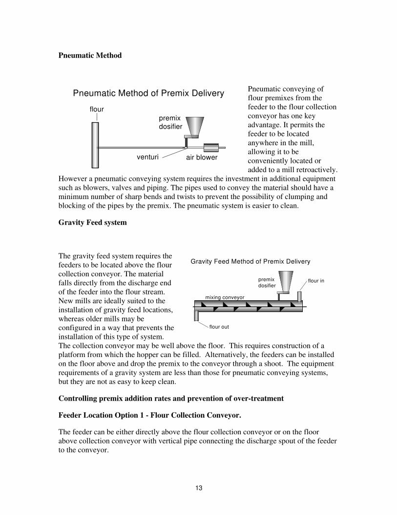
Pneumatic Method
Pneumatic conveying of flour premixes from the feeder to the flour collection conveyor has one key advantage. It permits the feeder to be located anywhere in the mill, allowing it to be conveniently located or added to a mill retroactively.
However a pneumatic conveying system requires the investment in additional equipment such as blowers, valves and piping. The pipes used to convey the material should have a minimum number of sharp bends and twists to prevent the possibility of clumping and blocking of the pipes by the premix. The pneumatic system is easier to clean.
Pneumatic Method of Premix Delivery
premixdosifier
flour
air blowerventuri
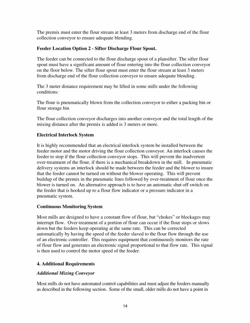
Gravity Feed system
The gravity feed system requires the feeders to be located above the flour collection conveyor. The material falls directly from the discharge end of the feeder into the flour stream. New mills are ideally suited to the installation of gravity feed locations, whereas older mills may be configured in a way that prevents the installation of this type of system. The collection conveyor may be well above the floor. This requires construction of a platform from which the hopper can be filled. Alternatively, the feeders can be installed on the floor above and drop the premix to the conveyor through a shoot. The equipment requirements of a gravity system are less than those for pneumatic conveying systems, but they are not as easy to keep clean.
Gravity Feed Method of Premix Delivery
flour in
flour out
mixing conveyor
premixdosifier
Controlling premix addition rates and prevention of over-treatment
Feeder Location Option 1 - Flour Collection Conveyor.
The feeder can be either directly above the flour collection conveyor or on the floor above collection conveyor with vertical pipe connecting the discharge spout of the feeder to the conveyor.
13
The premix must enter the flour stream at least 3 meters from discharge end of the flour collection conveyor to ensure adequate blending.
Feeder Location Option 2 - Sifter Discharge Flour Spout.
The feeder can be connected to the flour discharge spout of a plansifter. The sifter flour spout must have a significant amount of flour entering into the flour collection conveyor on the floor below. The sifter flour spout must enter the flour stream at least 3 meters from discharge end of the flour collection conveyor to ensure adequate blending.
The 3 meter distance requirement may be lifted in some mills under the following conditions:
The flour is pneumatically blown from the collection conveyor to either a packing bin or flour storage bin
The flour collection conveyor discharges into another conveyor and the total length of the mixing distance after the premix is added is 3 meters or more.
Electrical Interlock System
It is highly recommended that an electrical interlock system be installed between the feeder motor and the motor driving the flour collection conveyor. An interlock causes the feeder to stop if the flour collection conveyor stops. This will prevent the inadvertent over-treatment of the flour, if there is a mechanical breakdown in the mill. In pneumatic delivery systems an interlock should be made between the feeder and the blower to insure that the feeder cannot be turned on without the blower operating. This will prevent buildup of the premix in the pneumatic lines followed by over-treatment of flour once the blower is turned on. An alternative approach is to have an automatic shut off switch on the feeder that is hooked up to a flour flow indicator or a pressure indicator in a pneumatic system.
Continuous Monitoring System
Most mills are designed to have a constant flow of flour, but “chokes” or blockages may interrupt flow. Over-treatment of a portion of flour can occur if the flour stops or slows down but the feeders keep operating at the same rate. This can be corrected automatically by having the speed of the feeder slaved to the flour flow through the use of an electronic controller. This requires equipment that continuously monitors the rate of flour flow and generates an electronic signal proportional to that flow rate. This signal is then used to control the motor speed of the feeder.
4. Additional Requirements
Additional Mixing Conveyor
Most mills do not have automated control capabilities and must adjust the feeders manually as described in the following section. Some of the small, older mills do not have a point in
14
the system with a known, constant flow of flour. This makes continuous fortification difficult to achieve. One solution to this is to install a mixing conveyor running from a flour holding bin to the packout bin. The feeder would drop or blow the premix into the start of the special conveyor. Once again the 3 meter requirement to ensure adequate blending of premix with the flour needs to be met.
SECTION II. Procurement of Feeders and Mixers
This section covers:
- Manufacturers and suppliers from Europe, North America and from developing countries with contact details and recommendations based on technical suitability where applicable.
- Assessment of the costs and funding options and proposed models and key options that can be used under different circumstances and in different countries/regions.
Feeder Manufacturers:
The following is a list of Feeder Manufacturers and suppliers:
1. Acrison International, 27 Maria Road, Woodcliff Lake, NJ 07675 USA Telephone +1 201 476 0577 Fax +1 201 476 1053
2. Agromatic AG, Goldingstrasse 30 CH-8637 Laupen/Zurich, Switzerland.
Telephone +41 5525-62100 fax +41 5525-62111 Contact U. Deiner E-mail: [email protected] Website: www.agromatic.com
3. *American Ingredients Company, 3947 Broadway, Kansas City, MO 64111,
USA. Telephone +1 816 561 9050 Fax +1 816 561 0422 Contact Ryan Simmons. E-mail [email protected] Website www.americaningredients.com
4. Buhler AG, 9240 Uzwil, Switzerland. Telephone +41 7195 51111 Fax +41 7195
53742 Contact Martin Schlauri E-mail: [email protected] Website: www.buhlergroup.com
5. Codema Inc. 11790 Troy Lane N., Maple Grove MN, 55369-9377 USA
Telephone +1 763 428 2266 Fax +1 763 428 4411 Contact Heinz Baecker Email:[email protected] Website: www.codemainc.com
6. Gericke SA, 7, rue GuyMoquet, Z.I du Val d’Argent, F-95100 Argenteuil, France
Telephone +33 1 39 98 29 29 Fax +33 1 39 82 29 74 E-mail [email protected] Website www.gericke.net
7. Golfetto/GBS Group Via Temanza, 1, 35134 Padova, Italy Telephone +49 049
894 9494 Fax +49 049 894 9400 E-mail: [email protected]
15

8. Jaymark, (Division of BDI Inc,) 74 Dorchester Close, St. Catherines, ON L2M 6V2 Canada Telephone +1 905 938 2882 Fax +1 905 938 2772 Contact Darryl Tateishi E-mail: [email protected]
9. K-Tron, International Inc., Pitman, NJ 08071-0888 USA Telephone +1 856 589
0500 Fax +1 856 589 8113 E-mail [email protected] Website: www.ktron.com 10. Muhlenbau, 490-G, IV Phase, KIADB, Peenya Industrial Area, Bangalore 560
058 India. Telephone +91 80 836 3744/45 Fax +91 80 836 3346 Contact S.K. Ramaprasad E-mail [email protected] or [email protected]
11. *Muhlenchemie GMBH, Kornkamp 40, D-22926 Ahrensburg, Germany./
Telephone +49 4102 239301 Fax +49 4102 239323 Contact L Kutschinski E-mail: [email protected] Website: www.muehlenchemie.de
12. Ocrim SPA, Via Massarotti, 76, Cremona, 26100 Italy. Telephone +39 0372 4011
Fax +39 0372 412692 Contact Luciano Bolzoni E-mail: [email protected] Website www.ocrim.com
13. *Research Products Co., PO Box 1460 Salina, KS 67402, USA Telephone +1 785
825 2181 Fax +1 785 825 8908 Contact Monte White E-mail [email protected] Website www.researchprod.com
14. Satake USA Inc., 9800 Townpark Houston, TX 77036 USA Telephone +1 713
772 8400 Fax +1 713 772 8484 Contact Chuck Vincent E-mail [email protected] Website www.satake-usa.com
15. Schenk Accurate Inc., 746 E.Milwaukee St. PO Box 208, Whitewater WI 53190-
9972 USA Telephone +1 414 473 2441 Fax 414 473 4384 E-mail [email protected] Website www.sarinc.com
* Indicates premix supplier as well.
Feeder Manufacturer Recommendations
The selection of Feeder Manufacturers listed above has been based on the following criteria:
1. The equipment supplied by them is widely used in many countries with existing mandatory and voluntary fortification programs.
2. The equipment is used for adding flour additives and bakery improvers during the milling process where a high degree of accuracy is required to provide consistent flour performance at the bakery level.
3. Each manufacturer and supplier has several years of experience in the design, selection of appropriate equipment, installation and training of mill personnel for feeders.
16
4. Each manufacturer and supplier has established a good reputation with their mill customers and marketplace both domestically and internationally.
5. Due to the demand for simple feeders some feeder manufacturers are in the process of designing simple feeders which are cheaper versions of existing models. It is recommended that feeder manufacturers be approached by agencies such as the Micronutrient Initiative, UNICEF and the World Food Program for less costly versions of the their current line of feeders
Costs for Feeders and Installation
This section covers the costs for the procurement and installation of feeders and ancillary equipment (if required) for flour fortification programs. In order to establish what the best type of feeder is for a particular mill it is important to examine the criteria which need to be followed in the selection of feeders.
Criteria used to determine the selection of feeders.
The selection of feeder type for use in a flour mill must take into account the type of mill, the equipment, the layout and the performance of the mill under normal operating conditions. The following criteria need to be addressed as part of the feeder selection process:
1. Compatibility with existing mill equipment and layout.
If the mill is a simple mill with manual controls and simple mill control panel used to run the mill then a highly sophisticated feeder (more expensive) with many control options would not be needed and a simpler feeder (cheaper alternative) would be adequate.
2. Volumetric Feeders versus Gravimetric/Loss-in-weight Feeders
Gravimetric feeders measure the weight of the material as it is being discharged and the weight is automatically adjusted to meet the target feed rate. Volumetric feeders deliver a volume of material per unit of time. The weight of material being discharged can then be determined using sample calibration.
Volumetric feeders are simple and relatively inexpensive but they cannot detect or adjust to variations in the density of material being discharged. In the case of typical micronutrient premixes used in the milling industry today the density of such premixes does not vary significantly. In this case volumetric feeders will perform to the desired feeding accuracy. Volumetric feeders can suffer from uneven discharge rates due to the amount of material in the hopper above the screw feed and potential material build up on the feed screw. This problem can be overcome by designing some form of material agitation in the hopper above the discharge screw. The agitation device can be:
- Flexible lower side walls with external paddles massaging the flexible walls
- Vibrator motor on the fixed walls of the hopper
17
- Agitating or material conditioning screw above the discharge screw
3. Gravimetric/Loss-in-Weight Feeders for New Mill Construction
The specifications for the construction of new large scale mills today usually include the installation of flour scales and wheat scales to accurately measure production rates and to provide automatic control of the flour mill. In this case the incremental cost of installing a gravimetric feeder for micronutrient premixes is very small compared to the overall cost of the new mill. These types of feeders can be equipped with suitable PC compatible interfaces to allow for full automation of the milling and fortification process and monitoring system used for mill control.
Recommendations for Feeder types in different mills
These recommendations are applicable to any region in the world where national fortification programs are being proposed and implemented. The size of the mill and the existing mill layout are the governing factors rather than the region or country which determine the type of feeder to be used.
Simple Volumetric Feeder ($1,500)
For use in Small size Mills (less than 100 MT/day grain capacity), in existing mills currently equipped with manual controls and simple mill control panels
Volumetric Feeder ($6,000)
For use in Medium and Large size Mills (greater than 100 MT/day grain capacity) in existing mills currently equipped with manual controls and simple control panels
Volumetric Feeder ($6,000-$10,000) and Electronic control system
For use in Medium and Large size Mills (greater than 100 MT/day grain capacity) in existing mills currently equipped with electronic control interfaces and electronic mill control panels
Gravimetric/Loss-in-Weight Feeders (+ $10,000)
For use in New mills of any size equipped with flour scales and or wheat scales (1st Break scales) and in existing Medium and Large size Mills (greater than 100MT/day grain capacity) equipped with existing flour scale and electronic or computer control systems.
Recommendations for additional blending Equipment
- If a mill does not have at least 3 meters of total conveyor length after the discharge of the feeder and before the packing equipment then an additional blending conveyor will need to be included in the revised process flow. The total length must be at least 3 meters.
- If the existing conveyor space is less than 3 meters BUT discharges into a blowline to the flour storage bin then additional blending equipment is NOT required.
18
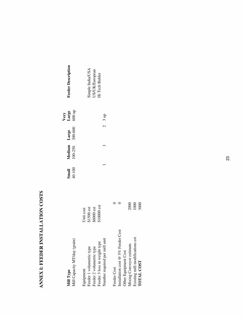
Feeder Costs
Feeder Installation Cost Spread Sheet
To assist in the costing process for feeders a spreadsheet has been developed in Excel format which is attached to this section. The spreadsheet highlights the different size mills, feeder types and other costs that need to be considered for installation of feeders.
These costs are considered to be capital costs and therefore under Generally Accepted Accounting Practices (GAAP) the capital costs can be depreciated over a specific time frame. The actual depreciation time frame can range from 10-20 years.
Actual costs from quotations and tender documents need to be entered into the Excel spreadsheet using the format given in Annex 1.
Funding Options for Feeders
The acquisition and installation of feeders is a key component of any flour fortification program but the cost can be a barrier to the implementation of a fortification program particularly under conditions in a developing country.
These conditions include the following:
1. Strict financial controls imposed by a government on wheat prices, flour prices and operating profit margins. In some countries the operating profit margins can be so low that the actual cost of fortification (premix) and the depreciated cost of the equipment exceed the profit margins resulting in operating losses.
2. Reliance of a government on high levels of import duties and other taxes for imported premix and equipment.
3. Fundamental economic conditions in the milling industry of a country with milling over capacity and lack of demand for flour. This results in operating at break-even or at a loss.
4. Strict price controls on bread and staple foods made from flours.
Recommendations
Under these conditions, alternative means need to be followed to allow for the implementation of a flour fortification program. The following recommendations can and have been used to assist countries with the implementation of flour fortification programs on a national scale.
1. Flour fortification should be part of a national plan to combat micronutrient malnutrition.
2. Advocacy programs to show that flour fortification has both an Economic Impact and Public Health Benefit. This approach requires the development of an advocacy program that shows the cost benefit analysis of flour fortification by reducing health cost burdens
19
of micronutrient malnutrition and improving economic performance through increased productivity and higher cognitive ability of children (longer term effect)
3. Use of development bank funds for the capital investment and start up of the program. World Bank, Africa Development Bank, Asian Development Bank, Southern Africa Development Bank have programs which would qualify for investment loans. In some cases for countries, designated as Highly Indebted Poor Countries (HIPC), where they have consistently repaid loans, the World Bank is arranging for these loans payments to be set up for investment in social programs, healthcare and education. These funds can be used for setting up flour fortification programs.
4. Inserting ongoing fortification costs (premix, QA/QC and Monitoring and Evaluation) as a line item into the Ministry of Health annual budget. As the benefits of fortification start to flow through after implementation there should be reductions in the incidence of disease due to micronutrient malnutrition.
5. Establish long term supply contracts with micronutrient suppliers (2 year minimum) to include feeders as part of the contract. Many micronutrient suppliers are willing to provide feeders as part of a long term supply contract.
6. Develop partnerships with international agencies such as UNICEF, WFP, WHO, bilateral agencies such as CIDA, USAID, DFID, NGOs and international agencies such as MI and GAIN.
SECTION III. Technology Transfer
As flour fortification becomes a widespread and accepted intervention in the effort to control micronutrient malnutrition the demand for feeders will increase. It is evident that local or regional production of feeders will become an important way of reducing the capital cost of flour fortification. As has been shown the technology of feeders is relatively simple especially for volumetric feeders. However there is a reluctance on the part of some governments to use feeders made locally due to issues related to lack of performance and unreliability. Consequently governments have relied on imported feeders. In addition it must be stated that feeder suppliers may be reluctant to supply feeders protected by international patents to some countries whose national patent protection laws are either weak or not enforced.
Recommendations
To assist developing countries in the implementation of flour fortification programs the following options can be explored.
1. Licensing Manufacturing Agreements
Some of the current manufacturers of feeders may be willing to enter into licensing manufacturing agreements with reputable manufacturers in developing countries. This will only occur in those countries whose governments can uphold and enforce existing international protocols and laws related to commercial copyright and patent protection.
20
2. Design of low cost feeders by current feeder suppliers
In this case there are some suppliers who have already recognized the need for lower cost simple feeders which are reliable for use in developing countries. These suppliers are in the process of developing prototypes to meet the demand of this new market for feeders.
Feeder Specifications
General Requirements
Feeders are used in the flour milling industry to add dry ingredients such as vitamin- mineral premixes, bakery flour additives and enzyme preparations to flour as the flour is milled.
The following specification parameters should be established and used for the procurement of feeders. These parameters will detail the major components and features required to ensure that feeders will operate under normal conditions found in flour mills.
Specification Parameters for Feeders
The following parameters should be included in the general specifications for feeders to ensure adequate performance during the flour fortification process:
1. Feed Rate: Expressed volumetrically in deci-litres or litres per hour (cubic feet per hour)
2. Discharge Outlet: Screw diameter sizes in centimeters (or inches)
3. Electrical Requirements: Voltage (110 or 220), Cycles (50 or 60 Hz),
Phase (1 or 3)
4. Motor: HP rating, Voltage, RPM, AC/DC, Cycles (50 or 60 Hz), Explosion proof
5. Controls: Speed Range, Voltage, Cycles, Computer or Control Panel Interface
6. Contact Materials: Stainless steel (preferred), Plastic linings and types approved for food use
7. Non-Contact Materials: Stainless steel, Mild
8. Hopper Capacity: Expressed in litres (cubic feet)
9. Weight: Expressed in kg (pounds)
10. Additional Hopper Capacity: Expressed in kg (pounds) Minimum 4 hour production capacity
21

Control System Requirements
Potentiometer motor speed controls,
Programmable controller system interface with mill control panels and interlock with flour conveyor motors.
Voltage Regulator system to protect electronic controls
Surge Protection system to prevent control system damage
22
AN
NE
X I
: F
EE
DE
R I
NS
TA
LL
AT
ION
CO
ST
S
Cost
0
30
Mil
l T
yp
e
S
ma
ll
Med
ium
L
arg
e V
ery
La
rge
Fee
der
Des
crip
tio
n
Mil
l C
apac
ity M
T/d
ay (
gra
in)
40-1
00
100-2
50
300-6
00
600
up
Equ
ipm
ent
Un
it c
ost
Fee
der
1 v
olu
met
ric
type
$1500
est
Sim
ple
India
/US
A
Fee
der
2 v
olu
met
ric
type
$6000
est
US
/UK
/Eu
ropea
n
Fee
der
3 l
oss
in
wei
gh
t ty
pe
$100
00
est
Hi
Tec
h B
uh
ler
Nu
mb
er r
equ
ired
per
mil
l u
nit
1
1
2
3 u
p
Fee
der
Inst
alla
tio
n c
ost
@ 5
% F
eed
er C
ost
0
Oth
er E
qu
ipm
ent
Co
st
Mix
ing C
on
vey
or
esti
mat
e2
000
Ex
isti
ng m
ill
mo
dif
icat
ion
ses
t1
000
TO
TA
L C
OS
T
00
23
ANNEX II: DIAGRAMS AND PHOTOGRAPHS
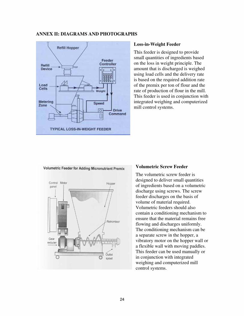
Loss-in-Weight Feeder
This feeder is designed to provide small quantities of ingredients based on the loss in weight principle. The amount that is discharged is weighed using load cells and the delivery rate is based on the required addition rate of the premix per ton of flour and the rate of production of flour in the mill. This feeder is used in conjunction with integrated weighing and computerized mill control systems.
Volumetric Screw Feeder
The volumetric screw feeder is designed to deliver small quantities of ingredients based on a volumetric discharge using screws. The screw feeder discharges on the basis of volume of material required. Volumetric feeders should also contain a conditioning mechanism to ensure that the material remains free flowing and discharges uniformly. The conditioning mechanism can be a separate screw in the hopper, a vibratory motor on the hopper wall or a flexible wall with moving paddles. This feeder can be used manually or in conjunction with integrated weighing and computerized mill control systems.
24
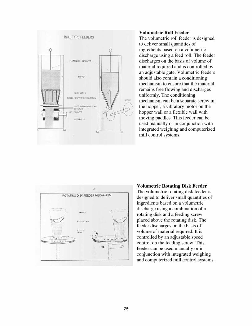
Volumetric Roll Feeder The volumetric roll feeder is designed to deliver small quantities of ingredients based on a volumetric discharge using a feed roll. The feeder discharges on the basis of volume of material required and is controlled by an adjustable gate. Volumetric feeders should also contain a conditioning mechanism to ensure that the material remains free flowing and discharges uniformly. The conditioning mechanism can be a separate screw in the hopper, a vibratory motor on the hopper wall or a flexible wall with moving paddles. This feeder can be used manually or in conjunction with integrated weighing and computerized mill control systems.
Volumetric Rotating Disk Feeder The volumetric rotating disk feeder is designed to deliver small quantities of ingredients based on a volumetric discharge using a combination of a rotating disk and a feeding screw placed above the rotating disk. The feeder discharges on the basis of volume of material required. It is controlled by an adjustable speed control on the feeding screw. This feeder can be used manually or in conjunction with integrated weighing and computerized mill control systems.
25
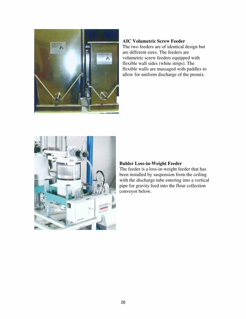
AIC Volumetric Screw Feeder The two feeders are of identical design but are different sizes. The feeders are volumetric screw feeders equipped with flexible wall sides (white strips). The flexible walls are massaged with paddles to allow for uniform discharge of the premix.
Buhler Loss-in-Weight Feeder The feeder is a loss-in-weight feeder that has been installed by suspension from the ceiling with the discharge tube entering into a vertical pipe for gravity feed into the flour collection conveyor below.
26
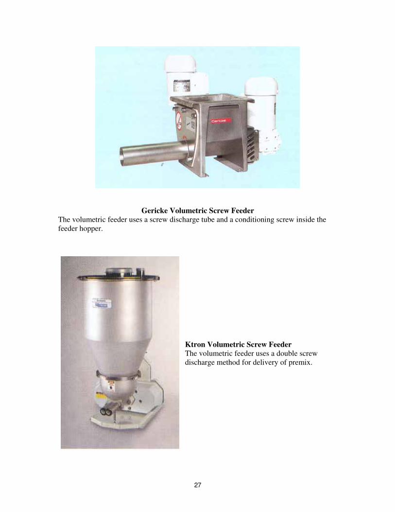
Gericke Volumetric Screw Feeder The volumetric feeder uses a screw discharge tube and a conditioning screw inside the feeder hopper.
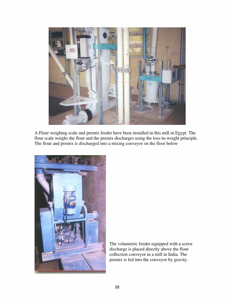
Ktron Volumetric Screw Feeder The volumetric feeder uses a double screw discharge method for delivery of premix.
27
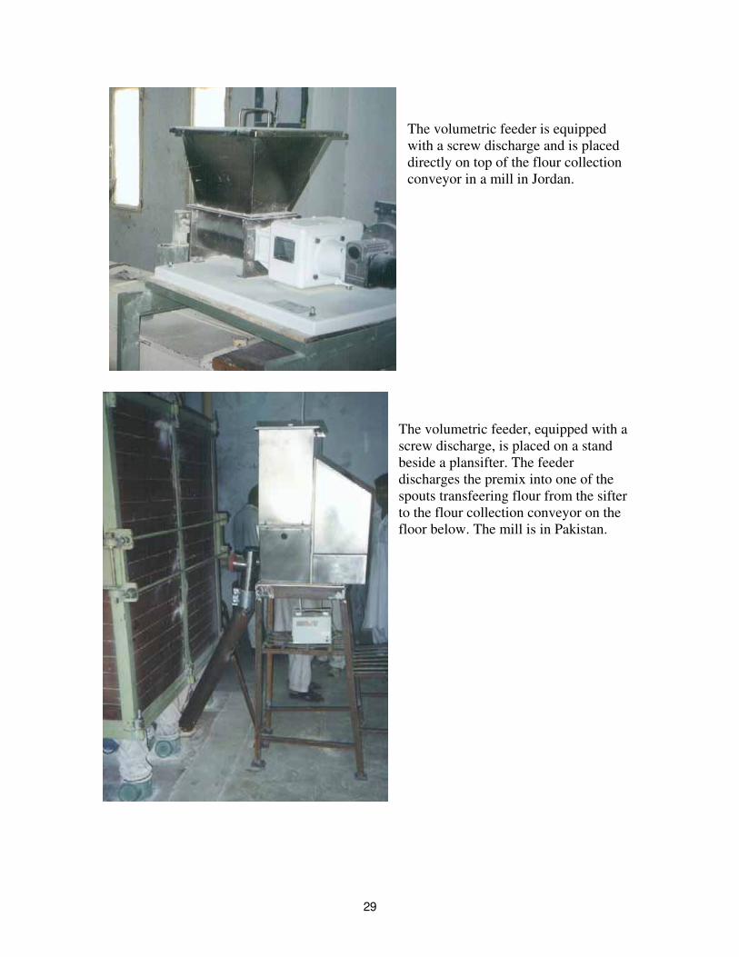
A Flour weighing scale and premix feeder have been installed in this mill in Egypt. The flour scale weighs the flour and the premix discharges using the loss-in-weight principle. The flour and premix is discharged into a mixing conveyor on the floor below
The volumetric feeder equipped with a screw discharge is placed directly above the flour collection conveyor in a mill in India. The premix is fed into the conveyor by gravity.
28
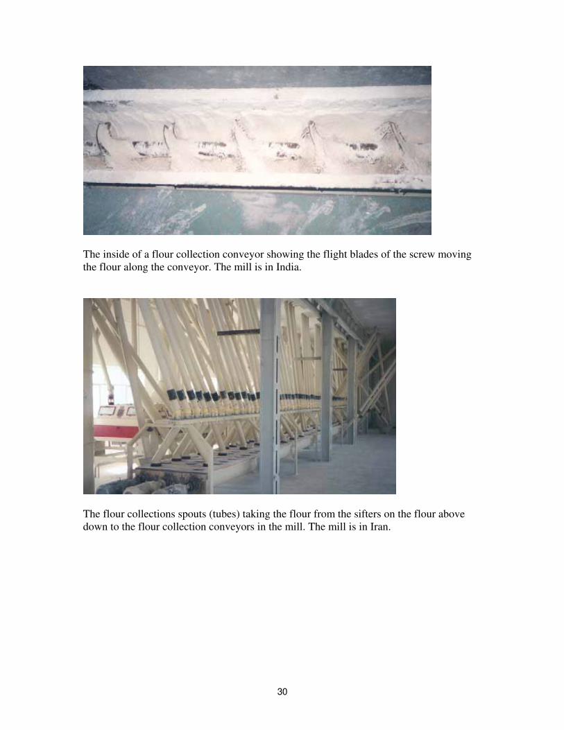
The volumetric feeder is equipped with a screw discharge and is placed directly on top of the flour collection conveyor in a mill in Jordan.
The volumetric feeder, equipped with a screw discharge, is placed on a stand beside a plansifter. The feeder discharges the premix into one of the spouts transfeering flour from the sifter to the flour collection conveyor on the floor below. The mill is in Pakistan.
29
The inside of a flour collection conveyor showing the flight blades of the screw moving the flour along the conveyor. The mill is in India.
The flour collections spouts (tubes) taking the flour from the sifters on the flour above down to the flour collection conveyors in the mill. The mill is in Iran.
30
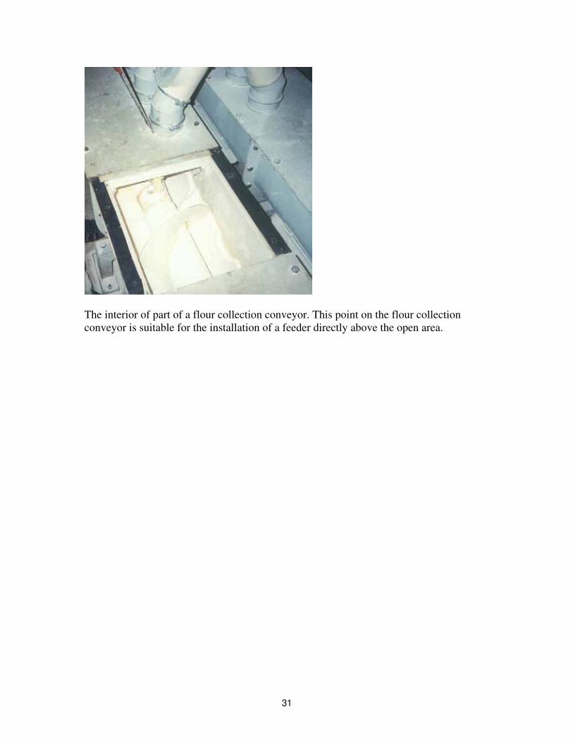
The interior of part of a flour collection conveyor. This point on the flour collection conveyor is suitable for the installation of a feeder directly above the open area.
31