feedback works in rivers - intakes
DESCRIPTION
intakesTRANSCRIPT

HEADWORKS IN RIVERS - Intake
1. Introduction
An intake, or capture, is a hydraulic structure intended to derive from a few courses of water, River, stream, or channel; or from a Lake; or even from the sea, a part of the water available in this, to be used for a specific purpose, such as drinking water supply, irrigation, generation of electric energy, aquaculture, industrial installations, etc.
Fig. 1.1 Bypass channel in a river carrying heavy loads background.
2. DESIGN CRITERIA2.1. Location and alignment of an intake
If you have to place the take on curved sections, as already explained above, must be in the concave area, as is the part where sediments are in smaller amounts.
Extraction at 90 ° to the main flow is the least desirable. The structure must be aligned to produce a desired curvature at the entrance flow, and a deviation angle of about 30 ° -45 ° is generally recommended to produce this effect.
Losses of entry into an intake depending on the change in the direction of (enter admission), the degree of contraction and type of trash rack provided at the entrance. They are expressed in terms of the velocity as KV2/2g.
Input loss due to a change in the flow direction (inlet at an angle to the main stream) is given by
Δha=V2 / 2g-ͼVo2/ 2g (9.19)
Where Vo is the velocity of the main stream at the inlet, and is approximately 0.4 for α=90 ° y 0,8 for α=30 °.

2.2. HEIGHT BARRAGE
The height of the barrage is determined as the sum of the height at which the window is capturing the height of the window and the free edge is taken for security.
Fig. 2. Scheme barrage height.
2.3. PROFILE CREST BARRAGE The formula used for the profile is the Corps of Engineers US Army, which is shown in Figure 3. This was used to crown the barrage, but in order to give wider than structure and not make it very slender, a constant slope of 1: 1 was used in the downstream face.
2.4. DISSIPATING POOLPlacing the barrage on the river generates an increase in potential energy due to rising water levels that, when pouring water over it is transformed into kinetic energy causing erosion at the base of the landfill springing up the high speeds at that point.
2.5. STABILITY ANALYSIS BARRAJE The barrage is a concrete element that achieves its stability due to its own weight. Then the stability analysis of the structure under the most severe condition, which occurs when the flood flow occurs develops. The forces are taken into account are:
• The weight of the busbar• Buoyancy• The thrust due to the riverbed• The thrust due to the underpressure
2.6. OWN WEIGHT BARRAJE The weight of the element becomes the most important in the analysis of stability, strength because it is an element of gravity. This force must be able to counteract the forces that are unfavorable for stability. The resultant of this force is vertical and its action line contains the center of gravity of the structure.

For ease of calculation, the profile of the barrage has been divided into sections known to assess the magnitude and position of the force of gravity.
2.7. PUSH HYDROSTATICEl The puch hydrostatic is a force that results from the pressures produced by the flow of water. The magnitude of this force depends on the water level upstream in any time interval, so that the maximum value of the thrust is given to the design flow.
2.8. DUE TO PUSH THE RIVER BEDOn the upstream face of the barrage, there is a thickness of solids which are part of the riverbed which produces a thrust in the structure. The Bureau of Reclamation recommended for horizontal force, considering the solid and liquid specific gravity equal to 1.4 ton / m³.
2.9. SUB-PRESSURE DUE TO PUSHThe uplift force is that which arises from the thrust generated by the filtered water at the base of the barrage. To calculate this force groundwater analysis using Phase2 v8.005 Rocscience software company that performs the calculation of infiltration using the finite element method was performed. Also, in the analysis, it was considered rompepresiones holes and placed in dissipating pool to decrease the push model.
2.10. SLIP SAFETY FACTORSlippage in the barrage is produced by the horizontal thrust caused by the water and push solids riverbed. This phenomenon must be countered by the action of dead weight of the structure, as this causes a friction force away from the sliding position. It is recommended that the sliding safety factor must be greater or equal to 1.5.The sliding safety factor (FSD) is calculated as:
Where “∑FV” y “∑FH” is the sum of vertical and horizontal forces respectively. The coefficient of friction "Ø" is one that exists at the interface of the barrage and foundation soil.
2.11. SAFETY FACTOR TO DUMPThe safety factor is evaluated by calculating the overturning moments produced by the different forces and evaluated with respect to the foot heel barrage downstream, as this is the most critical situation. It is recommended that the safety factor is greater than 2.The safety factor to overturning (FSV) is calculated as:
2.12. FISH PASSES
Interests of environmental protection and fishery require the provision of appropriate facilities as part of dams and weirs. Salmon and trout are the main migratory fish. The smolts (young salmon) 1-2 years traveling the ocean after spawning in freshwater, while kelts return (fully developed) salmon to their spawning grounds after spending 1-3 years at sea.
2.12.1. Fish passing current facilities upa. fish ladder (fish pool and cross-pass)
Facilities upstream migrant fish, consisting of fish ladders, fish locks (elevators), trams and arrangements for the capture and transport of fish.
The right fish ladder is a series of polygonal (cross walls) and pools bypassing an obstruction (such as a dam or reservoir) for fish to migrate to the waters head in easy stages. This is accomplished by

creating a series of drops of about 300 mm-450 mm between the pools (Fig. 9.33) in a gradient of about 1 in 8 to 1 in 15 (for high heads). Pools rest of a larger size (usually twice the size of a common pool) are also provided after every 5-6 pools.
Fig. 9,33 Fish ladder
The pools are generally 1.2 m deep, 2-5 m long and 10.2 meters wide, depending on the number of fish that migrate. The transverse walls may be provided with notches-holes staggered, with speeds on the ladder to be about 0.5 ms 1. Guiny et al. (2005) investigated the efficiency of the different steps through the septum is on a pass from fish (hole, slot, landfill) and found it - with limited data - a strong preference of juvenile salmon migrating Atlantic to the type of hole.
The maximum swimming speed U (1 ms) of a fish is a function of the length of the fish L (m) and the water temperature T (° C) and is predicted (Zhou, 1982) by
U=0.7L/2t (9.30)
where t is the time of muscle contraction (related to the tail beat frequency) given by
t = 0.17L0.43 +(0,0028-0.0425L0.43) lnT-0,0077. (9.31)
Equations (9.30) and (9.31) are recommended for ranges
L=0,05 m-0,80 m y T=2 ° C-18 ° C. The fish may be able to swim in this speed for a specified time (time of resistance, tm), which is also a function of the length of the fish and the water temperature and is given by
tm=E/(|Pc - Pr|) (9.32)
where E (energy storage)≈19400L3, Pc (chemical power) ≈0.97e 0.0052TU2.8L-1.15 y Pr (power supplied)≈48L3. It is suggested that sometimes swimming speed and endurance as proposed by equations (9.30) and (9.32) must not be exceeded in the design of a fish pass.
Flow control structures such as flood relief channels shall be designed that fish are not stranded; the minimum gate opening should be around 0.3 m and 0.3 m water velocity not more than 3 m s-1 (unlike charge of about 450 mm and a discharge rate of 0.27 m3 s -1).
b. Pass Denil fish
The pass Denil fish, consists of closely spaced wall (for energy dissipation) and at an angle to the axis of the channel to form secondary channels for fish passage. A typical pass Denil fish with a channel

width (b) (of, say, 0.9 m) may consist of a simple single plane wall is rectangular opening on a V-shaped opening (notch-like compound) fixed at a distance of approximately 2 / 3b (0.6 m) inclined upstream at an angle of 45 ° to the slope channel bed itself should not exceed 1: 4; the width of the opening is about 0.58b, while the height of the floor of the V-shaped opening above the channel bed 0.24b is around its top (the bed) about 0.47b . Pools big break (3 m long, 2 m wide 1.2 m deep) are provided in the vertical intervals of 2 m. An example of the complex Denil fish pass is Ennistyman in Inagh River in the Republic of Ireland.
c. raising fish (Borland type)
The elevators fish are intended primarily for high structures and arrangements seizure lift the Borland fish are shown in Fig. 9.34.
Fig. 9.34 Borland ascensor peces
2.12.2. Fish pass downstream facilities
The focus speed screens is generally maintained at about 0.5 ms-1, while for the blind diverters is about 1 ms-1 to maintain required levels of turbulence. Fish screens are generally of any mechanical or electrical.
Fig. 9.35 Fishing intake screen hydropower
3. TYPES OF INTAKES3.1. Lateral taken without damming (direct drive)
3.1.1. MAKING WORK DIRECTLY IN RIVERSThe intake will be located on a stretch of the stream is safe from erosion, sedimentation and upstream of any discharge of residual type.
The dimension of the duct decision shall be one less than the minimum water level of the stream.

In the inlet will take a grid formed by rods and rod with a gap of 3-5 cm, the average speed
through the grid will be from 0.10 to 0.15 m / s, to avoid possible carryover material floating.
The minimum speed inside the conduit is 0.6 m / s, in order to avoid sedimentation.
The maximum speed limit is established by water features and duct material.
To carry out the project of making a work satisfactorily, it is necessary to consider carefully
hydraulic aspects, requiring define for the selected location, the following:
Average flow rates, maximum and minimum runoff on the runway.
The levels associated with maximum flow, minimum and average operating.
Estimation of sediment transport along the runway.
Water quality at the source.
3.2. Intake side of the river to the reservoir (JOINT DECISION OR CONVENTIONAL)
This is a shot that hits the uptake by closing the river with a structure called dam or diversion dam, which may be fixed or mobile depending on the type of material used. Will be fixed when a rigid member is used, usually concrete, and will be movable when gates are used steel or wood. Uptake in such intakes is performed through a window that can function as orifice or weir strap depending on the river.
3.2.1. MAKING WORK ON DAMS
In perennial runoff in the dry season when the water level does not cover the outlet, and the barrage is a weak structure, it is best to build a dam. The dikes are final structures built to obstruct the channel, which have been simplified in terms of its components, incorporating the intake, the pouring of leave and the drain line within the body of the dike (Figures 5 and 6 ).

Figura 5. Obra de toma en diques (planta).
Figura 6. Headworks in dams (lift).
3.2.2. MAKING WORK IN DIVERSION DAM
The diversion dams, generally speaking, are surface water exploitation in tight low currents, allowing the uptake of water for various uses. When river water is required exploited but topographic by low levels does not allow properly grasp, it is possible to build a small curtain in order to increase these levels for lateral branching. The diversion dam consists of: a pouring curtain, the intake structure and cleanliness. The intake consists of holes housed in a wall, parallel to the flow channel, filled with hatches and operated with manual or electric mechanisms (Figure 6).
3.2.2.1. HYDRAULIC DESIGN
For the hydraulic design of the diversion dams should consider the following aspects:
Definition of minimum and maximum levels of operation, at the site of the diverter, for levels
of operation, and the hydraulic load for the required flow.
Dimensions of the hole.
Maximum Expense passing through the gates.
Capacity of the lift mechanism.
3.2.2.2. SIZING THE HOLE
The passage of the intake usually through the wall that separates the sand trap and the slopes of the channel, thus, the hydraulic analysis is to consider a short tube orifice. The term controlling the operation of an orifice is given by:
Q = output bypass or normal spending decision, m3 / s
C = discharge coefficient or expense analyzed for the particular hole, may be considered for C = 0.8,
whereby the size of the gate or gates is determined.

A = area of orifice in m2.
g = acceleration due to gravity, 9.81 m / s2.
h = hydraulic head over the orifice, in m.
3.2.2.3. DETERMINATION OF THE CAPACITY OF LIFT MECHANISM
The capacity of the lift mechanism (CME) can be defined using equation 14:
f = frictional forces are produced by buoyancy (E), acting on the damper blade = μE.
μ = coefficient of friction between the materials of the gate and the guides; to evaluate the friction coefficient can be considered for design purposes, 0.35 for cast iron gates iron seating polished machine.
E = The buoyancy acting on the damper blade, kg.
Fig. 7. Headworks in diversion dam
3.2.3. MAKING WORK IN STORAGE DAMS
Dams have various works to ensure its efficient operation under various circumstances: curtain, headworks and leave work. The water flowing through the channel of a river is trapped and stored through the curtain, and its use is conducted by an intake.
3.2.3.1. DESCRIPTION OF THE CAPABILITIES
Before addressing the hydraulic design decision is convenient to describe the capabilities of use or operation involving the design of a dam, indicated in elevations-capacity curve (Figure 8).
NAME: corresponds to the maximum water level in the extraordinary body of water.
NAMO: is the maximum water level operating in the water body; this bound is also known as N.A.N. (Normal Water Level) and is defined by the level of the spillway crest.
N / A. .: min is the minimum level or dimension operating water in the body of water, the place where the uptake, and corresponds to the volume intended for silt.
Cr: flood control capacity, it is seen as the stored volume between the NAME and the NAMO; this capacity of the spillway gates for dam safety is operating. This maximum is given by the level of storage to close the gates.

C.U .: capability is useful; is the volume of water used to meet the demands of the fluid (irrigation, drinking water, cattle, etc.), and which is constituted as the directly usable volume of the dam (see figure 4). This volume corresponds to the stored (CU) between the NAMO and NA min., about the depth of the holes in the camera shots are placed vertical control.
Silt Capacity (Cz) is described as the volume below the Namin stored. This capability is also called dead capacity and is credited with the life of reservoirs, since it is considered that the operation ends when the silt level is exceeded.
3.3. background intake (intake Tyrolean)
The Tyrolean intake occupies a special position. The water to be diverted is taken through a collecting channel embedded in the river bottom and covered with a screen (Fig. 14). The screen bars are placed in the flow direction and inclined in the downstream direction so that the bed load outside the coarse particle collection channel and transported downstream remains. Particles that are smaller than the inner width between the screen bars are introduced into the collecting channel with the water and they must subsequently be separated from the water for the generation of energy by suitable discharge. The lower part of the decision can be built on the same level as the bottom of the river or in the form of a windowsill.
For the construction of the intake care fund should consider the following points:
- Formation of massive concrete body as it is subject to heavy abrasion forces,
- Recommended slope b of the screen angle between 5 ° and 35 °,
- Stable display the bars of Training,
- Sufficient freeboard between the water surface in the collection channel and the upper edge of the screen (at least 0.25 t = maximum depth of water in the collection channel),
- Pending enough in the collection channel to evacuate the solid matter that has entered through the screen, the previous classification of this matter by the inner width between the rails of protection. In planning the dimensions of a Tyrolean intake should be noted that all the input stream is taken from the river until the capacity limit of the screen is reached. If this maximum amount of extraction is greater than the lowest discharge, water is drained from the queue. If the inflow exceeds the capacity limit of the screen (eg during floods), the amounts are not diverted flow through the screen into the water below.
This is why the maximum amount of water for power generation can be limited to be evacuated safely over a bottom outlet that take a fixed side dams.
4. HYDRAULIC DESIGN
4.1. SPILLWAY OF TOO
The basic form excessively spillway (medieval) is derived from the lower envelope of the water film generated due to a high vertical rectangular notch V0≈ approach speed and fully ventilated space below the water level (P = p0), as shown in Fig. 4.1
Fig. 4.1 Spillway gate referral form.
To a notch width b, h head, and the discharge coefficient Cd is the discharge equation:
That for Vo = 0, reduces to:
C’d es de 0,62.
Fig. 4.2 Standard spillway crest (after the Experimental Station US Army Waterways, 1959)
con K=0,5 y n=1,85
(curva en la Fig. 4.5 (Novak y Cábelka, 1981)).

Para Hd= Hmax la presión es atmosférica y Cd= 0.745. Para Hd> Hmax la presión sobre el aliviadero es mayor que la atmosférica y el coeficiente de descarga será 0.578< Cd< 0.745. Para Hd< Hmax las presiones resultan negativas, alcanzando el nivel de cavitación para H=2HD con Cd=0.825. Por razones de seguridad se recomienda no exceder el valor Hmax=1.65Hd con Cd 0,81. La descarga a través de puertas parcialmente elevada puede ser calculada (Fig. 4.7 (a)) a partir de To Hd = Hmax pressure is atmospheric and Cd = 0.745. To Hd> Hmax pressure on the spillway is greater than atmospheric pressure and the discharge coefficient is 0.578 <Cd <0.745. To Hd <Hmax pressures are negative, reaching the level of cavitation H = 2HD with Cd = 0.825. For security reasons it is recommended not to exceed the value Hmax = 1.65Hd with Cd 0.81. Through discharge doors partially raised can be calculated (Fig. 4.7 (a)) from
o, mejor a partir de:
where "a" is the distance inlet lip surface of the landfill, and the effective head Hc in the closed spillway (≈H) (0.55 <Cd2 <0.7).
For thin sections of dams, for example in dams arc length must be reduced.
where n is the number of contractions and K is a coefficient which is a function of the spring and form H; (0 <K <0.09 with the upper limit of spring-semicircular nose and H / Hd = 0.2).
Fig. 4.7 spillway gate with (a) doors and (b) displacement
An important design feature is the point at which self aeration overflow layer (in contact with the spillway) begins. The mechanics of the phenomenon of self-aeration; Li the distance (m) from the starting point of the ridge can be estimated using equation Hickox:
Li= 14.7q 0.53≈ 15q 1/2 (4.23)
where "q" is the specific discharge (discharge per unit length, m2s 1).
4.1. BARRAGE DESIGN 4.1.1. Definition

The barrage is built in the riverbed in order to retain water, producing lift its level to a height that ensures we capture a permanent structure.
The shape varies by type: geometry, available within the channel, building materials and project economics.
4.1.2. Types B a r r ag ea) Fixed barrage: A solid structure located across the width of the channel so that
reason backwater curve occurs upstream of the barrage can not be altered.b) Mobile barrage: consists of a system of gates placed across the width of the
riverbed and that in turn regulate the flow of water. From the hydraulic point of view it is recommended when the river floods has a period of very high flows.
c) Joint barrage: Constitu ye combining the above two formed in part by a fixed structure and the rest by a system of gates that are used for use as a clean channel solid material accumulated
4.1.3. Height Barrage ( P )
By this the ture is achieved raise or maintain or v the water in the river, so that the flow is derived to the main channel allowing passage of the leave above it.
Cc = Co + P + = Co + (ho + h + 0.20)
Y
Barraje
Muro de Encauzamiento
Construcción de barraje de derivación
Concreto f'c=175 Kg/cm2h
Ventana de Captación
P
ho
Where:
Cc: Cota barrage Crest (m.s.n.m)
Co: Coordinate of the riverbed. (m.s.n.m)
Ho: A ras lturaparaevitarar tredesedimentoshacia decision. (M).
Consider h0> 0.50 m.

h: Al ture pick window, (m)
0.20: Segundad the effect of waves and load factor. You can vary.
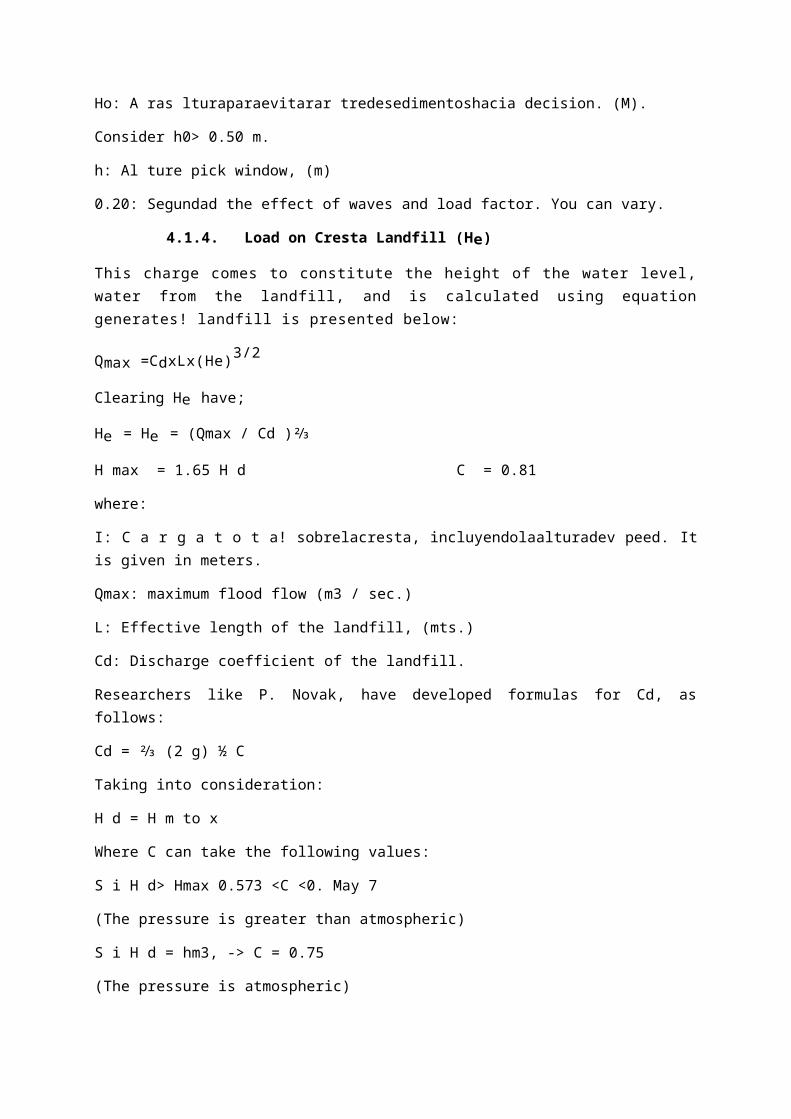
4.1.4. Load on Cresta Landfill (He)
This charge comes to constitute the height of the water level, water from the landfill, and is calculated using equation generates! landfill is presented below:
Qmax =CdxLx(He)3/2
Clearing He have;
He = He = (Qmax / Cd )⅔
H max = 1.65 H d C = 0.81
where:
I: C a r g a t o t a! sobrelacresta, incluyendolaalturadev peed. It is given in meters.
Qmax: maximum flood flow (m3 / sec.)
L: Effective length of the landfill, (mts.)
Cd: Discharge coefficient of the landfill.
Researchers like P. Novak, have developed formulas for Cd, as follows:
Cd = ⅔ (2 g) ½ C
Taking into consideration:
H d = H m to x
Where C can take the following values:
S i H d> Hmax 0.573 <C <0. May 7
(The pressure is greater than atmospheric)
S i H d = hm3, -> C = 0.75
(The pressure is atmospheric)
Hd = design height of the barrage.
(Negative pressures occur causing cavitation H = 2HD)
In general the first case does not present; in the second case does not consider the speed of arrival and the third case is considered the most suitable for that there is always a speed of arrival.
For security not exceed the value of:
H m a x = I . 6 5 ( H d ) C = 0 . 8 1
4.1.5. Speed Check (V)
It is one with which the waters are approaching the barrage and comes up before forming the depressive profile:

P + H c = Y + H r
Also :
V = Q/A = Q / (B)(Y)
H y = V2/ 2g = Q2 / 2g(B2)8Y2)
Hd = He -Hv
Where :
Qmax: Maximum flow. (m3 / s)
B: Channel Width (m)
Q: Landfill barrage height (m)
HE: Height Total Load (m)
Y: Strap Upstream the barrage, (m)
Hv: Height Velocity (m)
G: acceleration of gravity (m / s2)
A: Cross-sectional area of the river in the catchment area (m2)
Y: arrival speed (m / s)
Hd: net load on the crest (m)
4.1.6. Transition curve between the Escarpment and Flooring of Poza
B = Arctag 1/ Z
Being a circular curve:
T = R Tang ½
Some engineers (Mansen recommend an R = 0.5 (Hd) or 2 (Hd)..
4.1.7. Effect of backwater in the river by the construction of the barrage
A busbar in the bed of a river, originate formation water level in front of the landfill, which produces agricultural reindeer, roads, bridges artwork, etc. Necessary to determine the curve formed haven for 'the problems caused.

Desripiador
FIGURE No. 21 .Vista in Plant and Corle of a Ripper.
X = E 2 - E 1 / (SO - S 1)
Specific energy E = Y + V 2 / 2g Pending in the Fund
SO = Z 1 - Z 2 / X

Friction Slope
S 1 = (N2) (V2) / (2.22 R 1/3)
average Earring
S 1 = S11 + S 12/2
4.2. FLOORING OR MATTRESS SINK
Placing the barrage on the river generates an increase in potential energy due to rising water levels that, when i pour water over it is transformed into kinetic energy causing erosion at the base of the landfill springing up the high speeds at that point.
To control this erosive effect dissipation structures are built, as floorings, mattress sink, etc. which aim to form a hydraulic jump that achieves dissipate the kinetic energy .. In practice, the damper bed is rarely designed to control the total length of a free hydraulic jump paved bed, because such a situation might be too expensive.
Yes the water level downstream of the barrage, the shoulder is very Altay dives, the jet coming down the weir can continue downstream as a strong undercurrent so be dangerous to the runway.
Here are calculating the power dissipation based on the length of the mattress sink and straps
conjugates (Y, Y2) necessary for the formation of hydraulic jump.
FIGUA 12 Transition Curve Landfill and dissipating Poza
8.3. Sizing Pool
For the design of the pool dissipating need to first know the tie at the foot of the barrage and its conjugate tight. The tie at the foot of the barrage is calculated using the energy equation at the beginning of the barrage and the end of this:
It draws on the natural ground level and being "Az" the depth of the pool, the height of the barrage "H", the height of the water surface "Hd" must be the equation is now:
The value of "Hd" is calculated using the equation of the landfill:
The conjugate rod is calculated using the equation obtained from the principle of specific strength:
The length of the pool is calculated knowing dissipating values straps conjugates using various empirical formulas, which are presented in the Table 1:
Table 1. Equations for the length of the pool.
Sink mattress thickness is calculated using the formula:
Where "Sp" is the way of partial percolation and "St" is the way of all percolation, so this thickness varies by increasing percolation path. The coefficient of "4/3" is a safety factor and it is recommended that the thickness is greater than 0.90 m.
10.0. CLEAN CHANNEL
You can consider 1/10 the width between the wallsStructures is shunt and has always! sediment accumulation problem and bring these malfunctions of the work, low utilization, increased costs of operation and maintenance and temporary suspension of irrigation service.The clean channel located between! A window uptake and fixed barrage leads to so-called mobile barrage, designed to prevent the accumulation of stuff! solid front window capture.In times of flood serves to drain part of the cauda! water. The entry of water is controlled by a system of gates.

FIGURE 16. Diagram No underpressure for. high water.
Fig. 17. Under-pressure diagram 'p a r a minimum water.
10.1 Required for Channel Speed Clean
Its recommended location is perpendicular to the axis of the barrage weir and flow parallel to the river at an angle between 45 ° and
60 ° with the axis of uptake (may vary according to design criteria), unless a hydraulic model to determine other conditions is performed.
The f l u j or existing in the cane! must have a speed Ve able to drag ios sediments deposited. Mansen (2) has the following formula:
Vc.= ( 1 . 5 ) ( C ) ( D 1 / 2 ) ...........................................................................31
where:
Vc; Speed to start dragging, (m / s).

C: coefficient depending on the type of material, d = D: diameter of the largest grain.
Type of material C
Sand and Gravel rounded
Gravel square (rectangular)
Mixture of sand and gravel
3.2
3.9
3.5 a 4.5
10.2. Pending on Canal Clean
You should have a slope that generates speed clean. Mansen also recommends the following formula:
where:
Sc: Pending review. (%)
g: acceleration of gravity (m / s2)
n: Manning roughness coefficient.
q: Download per unit width. (m3 / s / m)
q = (Vc) 2 / g
The clean channel bottom near the window catchment must be below this threshold.
Also the water below end must match or be very close to the height of the mattress sink.
The design recommendations are:
- The clean channel must be estimated in at least twice the flow rate or equal to derive average flow.
- Can be calculated in approximate expenditure from which it is advisable to operate the clean channel in order to obtain a desirable operation.
This is done by considering a slope for channel around
0.01 to 0.02, or other value that suits the terrain profile and a width suitable template al. Velasco
- The width in the area clean is recommended to be one-tenth the length of the barrage. Need not be strictly applied because this will determine e! discretion of the designer.
By the continuity equation holds:
34

35
but:
Ac = (b) (Y)
b = width of channel flushes.
Y = Strut channel. It is considered equal to the elevation of the weir crest.
10.3. Scour Depth
The scour depth that will produce the maximum design flood to define the depth of foundation structures channeling, recruitment and referral is made by the expression given by Lischtvav - Lebedev, based on determining the condition of speed between the average speed current and the mean flow velocity is required to ablate a material of known diameter and density.
Ps = ds-Y0
36
Ps: scour depth.
Ds: P rof undidad after leaving the pro duc i ng so CAVAC. I Prof Normal undidad (wáter depth)
B : Effective width section.
U: Coef iciente the effect of contraction of the estrivos (see Table No 5)
Dn : Average diameter pa rt of dry particles in mm.
B : Coef iciente taking into account e! period of return that gas to pre sents X (E xp or what you ne ed n ep on of Dm) in mm.
11.1 Capture Window
Constitute entry or opening for bypass flow. Its location with respect to the channel bottom is bounded on the upper level along the crest of the barrage, must be at least 10 cm below

this. As for the lower level must be at a height such as to avoid the entrance of solid material therethrough. See Figure No. 5.
where:
h0: height to prevent entry of dredged material. 0.50 m is recommended. minimum.
h: Height pickup window.
The window capture function as broad crested weir in times of drought and as a hole in times of flood.
The flow characteristics are:
1 Case: In times of drought it is preferable to determine the formula of the landfill.
Q = 1.84 (L) (H) 3/2 (No Confracciones)
Q = C (L-O.1 Nh) h3 / 2 (With Contractions)
where:
Q = Flow to derive more the flow required for system operation valve (m3 / sec.).
L = length of the window (m).
h = height of the window (m).
C = 1.84 = standardized coefficient landfill.
N = Number of contractions.
Case II: For maximum design load, the flow of income is calculated using the expression for submerged orifices:
Q = C d (A) (2 g H) Vi
where;
Cd = (Cv) (Cc) = coefficient spending a hole.
Cv = experimental coefficient correction for loss of load (very close to 1)
Cc = Correction factor experimental vein shrinkage incoming liquid.
In addition:
V = Cv (2gh) 1/2
Ao = Cc (A), Ao = contracted Section.
These coefficients are used in circular and rectangular holes and are a function of the Reynolds number.
Thus in Figure No. 18 observed that when the Reynolds number Re> 105, the coefficients Cv, Cc, Cd gain constant values of: Cv = 0.99, C c = 0.605, Cd = 0.60
In low-rise rectangular holes. The coefficients take the same values, and the Reynolds number value "D" takes the minimum dimension! hole.

In general if the dimensions of the hole and carcas are not very small, the ratio is almost independent of them worth about 0.60, but as loads and dimensions decrease, this ratio increases somewhat, returning to decrease again when the load exceeds little hole dimensions. In fact the expenditure ratio is a complex function that influence viscosity, capillary module, its shape, size and temperature absorbed.
COMPUERTAS
The under sluices are the openings provided at the base of the weir or barrage. These openings are provided with adjustable gates. Normally, the gates are kept closed. The crest of the under-under sluice portion of the weir is kept at a lower level (1 1.5 m) than the crest of the normal portion of the weir. The suspended silt goes on depositing in front of the canal head regulator. When the silt deposition becomes appreciable the gates are opened and the deposited silt is loosened with an agitator mounting on a boat. The muddy water flows towards the downstream through the scouring sluices. The gates are then closed. But, at the period of flood, the gates are kept opened.
The main functions of under-sluices are:

o To maintain a well defined deep channel approaching the canal head regulator.
o To ensure easy diversion of water into the canal through the canal head regulator even during low flow.
o To control the entry of silt into the canal
o To help scouring and of the silt deposited over the under-sluice floor and removing towards the downstream side.
o To help passing the low floods without dropping the shutters of the weir.
Sluice discharge capacity following is provided:
Qu=2 (Qmax)channel
Qu=20 %¿
PILLARS
In the weirs, the pillars are provided at an interval of 10 m. 20 m. The pillars supporting a bridge decking and working platform for the operation of the gates.
The pillars are constructed generally monolithic with the ground. The springs must be high enough to keep the doors, clear the maximum flood level while making ample room to pass any floating debris under doors raised.
Embankments are generally simple and the side face of the vertical columns is often. Pillars should have separate bases. See Fig sgte.:
MUROS DE ENCAUZAMIENTO
River training works are required near the weir site in order to ensure a smooth and an axial flow of water, and thus, to prevent the river from outflanking the works due to a change in its course.

The river training works required on a canal headwork are:
(a) Guide Bank When a barrage is constructed across a river which flows through the alluvial soil, the guide banks must be constructed on both the approaches to protect the structure from erosion. Guide bank serves the following purposes: It protects the barrage from the effect of scouring and erosion. It provides a straight approach towards the barrage. It controls the tendency of changing the course of the river. It controls the velocity of flow near the structure.
(b) Marginal Bunds The marginal bunds are earthen embankments which are constructed parallel to the river bank on one or both the banks according to the condition. The top width is generally 3 m to 4 m. The side slope on the river side is generally 1.5: 1 and that on the country side is 2:1. The marginal bunds serve the following purposes: It prevents the flood water or storage water from entering the surrounding area which may be submerged or may be water logged. It retains the flood water or storage water within a specified section. It protects the towns and villages from devastation during the heavy flood. It protects valuable agricultural lands.
(c) Spurs or groynes (i) Spurs These are temporary structures permeable in nature provided on the curve of a river to protect the river bank from erosion. These are projected from the river bank towards the bed making angles 60o to 75o
with the bank of the river. The length of the spurs depends on the width of the river and the sharpness of the curve. The function of the spurs is to break the velocity of flow and to form a water pocket on the upstream side where the sediments get deposited. Thus the reclamation of land on the river bank can be achieved. The spurs may be of the following types: (a) Bamboo Spur (b) Timber Spur (c) Boulder Spur
(a) Bamboo Spur: In this type of spur, a box like compartment is prepared by driving bamboo piles at 15 cm centre to centre. The piles are secured by bamboo bracings. The hollow space is filled up with sand bags. It is permeable in nature and water can seep through its body. This type of spur is suitable for small rivers. This is purely temporary and requires repair work every year. The length of bamboo piles depends on bed condition.

(b) Timber Spur: In this type, a box like compartment is prepared by driving timber piles at 15 cm to 30 cm centre to centre. The piles are secured by wooden bracings. The hollow space is filled up by boulders. This spur is permeable but stable. This is recommended for bi rivers with high velocity of flow. The length of the timber piles depend on bed condition.
(c) Boulder Spur: In this type of spur, boulders are enclosed in G.I wire net in circular shape. The boulder should be heavy, varying from 30 kg to 50 kg and the wire net should be made of 4 mm diameter G.I wires. It is laid from the river bank towards the bed making an angle of 60o-75o with the bank. This type of spur is recommended for the rivers where velocity of flow is very high.
(ii) Groynes The function of groynes is similar to that of spur. But these are impervious permanent structures constructed on the curve of a river to protect the river bank from erosion. They extend from the bank towards the bed by making an angle of 60o to 75o with the bank. The angle may be towards the upstream or downstream. Sometimes, it is made perpendicular to the river bank. These are constructed with rubble masonry in trapezoidal section and the surface is finished with stone pitching or concrete blocks. o The stone pitching or the concrete blocks are set with rich cement mortar. o The length of the groyne depends on the width and nature of the river.

o The top width varies from 3 m to 4 m. The side slope may be 1½: 1 or 2:1. o The groynes are provided in series throughout the affected length of the river bank. o The spacing between the adjacent groynes is generally kept as 2L, where L is the length of the groyne. o These are recommended for the river where the permanent solution of erosion control is extremely necessary.
The groynes may be designated as follows: (a) Attracting Groyne: The groyne which is constructed obliquely to the bank by making an angle of 60 to 75o towards the downstream is known as attracting groyne, here the flow of water is attracted towards the bank, and the velocity of flow is reduced to such a extent that it can not cause any erosion to the bank. However, a bank protected of stone pitching is provided for safety.

(b) Repelling Groyne: A groyne which is aligned towards upstream at an angle of 60o to 75o with the river bank is known as repelling groyne. A still water pocket is formed on the upstream where silting takes place. Here, the bank protection is not necessary, because the flow of water does not touch the bank and there is no effect of erosion on the bank. But still boulder pitching should be provided for safety.
(c) Deflecting Groyne: The groyne which is constructed perpendicular to the river bank is known as deflecting groyne. Here the flow of water is deflected from bank by the perpendicular obstruction i.e. groyne. The flow of water follows an undulating path just outside the head of the groyne. An eddy current is formed on the upstream side of the groyne. This eddy current will not affect the river bank. But the bank protection is provided for safety.

THE DIVIDE WALL:
The divide wall is a masonry or concrete wall constructed at right angle to the axis of the weir.
The divide wall extends on the upstream side beyond the beginning of the canal head regulator; and on the downstream side, it extends upto the end of the loose protection of the under-sluices.
The divide wall is a long wall constructed at right angles in the weir or barrage, it may be constructed with stone masonry or cement concrete. On the upstream side, the wall is extended just to cover the canal head regulator and on the downstream side, it is extended up to the launching apron.
The main functions of the divide walls:

It separates the ‘under-sluices’ with lower crest level from the ‘weir proper’ with higher crest level.
It helps in providing a comparatively less turbulent pocket near the canal head regulator, resulting in deposition of silt in this pocket and, thus, to help in the entry of silt-free water into the canal.
It helps to keep cross-current, if any, away from the weir.
ESCALERA DE PECES
A narrow opening including suitable baffles or staggering devices in it is provided adjacent to the divide wall.
The fish ladder is provided just by the side of the divide wall for the free movement of fishes. Rivers are important source of fishes.
There are various types of fish in the river. The nature of the fish varies from type to type. But in general, the tendency of fish is to move from upstream to downstream in winters and from downstream to upstream in monsoons. This movement is essential for their survival. Due to construction of weir or barrage, this movement gets obstructed, and is detrimental to the fishes.
In the fish ladder, the fable walls are constructed in a zigzag manner so that the velocity of flow within the ladder does not exceed 3 m/sec
The width, length and height of the fish ladder depend on the nature of the river and the type of the weir or barrage.