february, 1963 prestressed concrete institute … news and... · the post-tensioning anchors can be...
TRANSCRIPT

c;.ItenisPublished Monthly by the February, 1963PRESTRESSED CONCRETE INSTITUTE Vol. 9, No. 2
Ii A

PRESTRESSED CONCRETE INHOME CONSTRUCTION
San Diego, California home featured a 60 ft. square, 10 inch thick, pest-tensioned lift slab roof. The post-tensioning anchors can be seen projecting from the ends of the slab producing a decorative effect. The roof wassupported on only four columns.
Greensboro, North Carolina, Southeastern Region Horizon Home Merchandising Winner. Attractive homeemployed precast prestressed beamsto carry the second floor living area.
Prestressed concrete is finding its waymore and more into home construction.Shown on these pages are four homesfrom the 1962 Concrete Industries Horizon Homes Program. Three of thehomes are of contemporary design andthe fourth is of a more traditionalnature. The interesting feature of thesehomes is the different ways in whichprestressed concrete is employed.
One home, the San Diego entry, wasa Western Region Design winner andfeatured an unusual post-tensioned liftslab roof. This home is believed to bethe first to ever employ this type ofroof. It requires only four columns tosupport the roof, and the walls can beplaced where ever you want them asthey are not required for support. Thiswould seem to be a home planners ideaof real flexibility, with 3,600 square feetof floor space and no bearing walls.
The prestressed roof is 60 ft. square.
Architect: Hester-Jones
C
2
jL
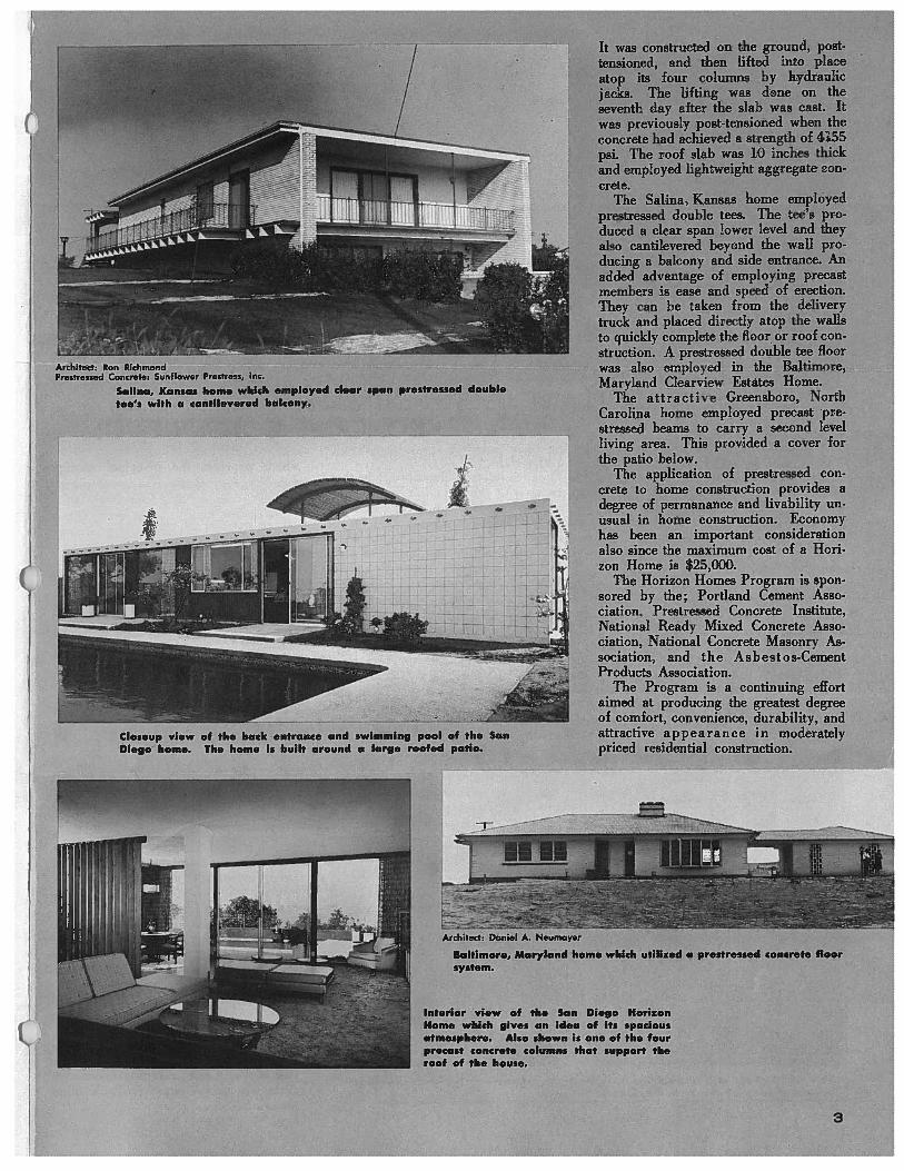
IArchitect: Ron RichmondPrestressed Concrete: Sunflower Prestress, Inc.
Sauna, Kansas home which employed clear span prestressed doubletee’s with a cantilevered balcony.
Closeup view of the back entrance and swimming pool of the SanDiego home. The home is built around a large roofed patio.
HrArchitect, Daniel A. Neumayer
Baltimore, Maryland home which utilized a prestressed concrete floorsystem.
Interior view of the San Diego HorizonHome which gives an idea of its spaciousatmosphere. Also shown is one of the fourprecast concrete columns that support theroof of the house.
It was constructed on the ground, post.tensioned, and then lifted into placeatop its four columns by hydraulicjacks. The lifting was done on theseventh day after the slab was cast. Itwas previously post-tensioned when theconcrete had achieved a strength of 4155psi. The roof slab was 10 inches thickand employed lightweight aggregate concrete.
The Sauna, Kansas home employedprestressed double tees. The tee’s pro.duced a clear span lower level and theyalso cantilevered beyond the wall pro.ducing a balcony and side entrance. Anadded advantage of employing precastmembers is ease and speed of erection.They can be taken from the deliverytruck and placed directly atop the wallsto quickly complete the floor or roof construction. A prestressed double tee floorwas also employed in the Baltimore,Maryland Clearview Estates Home.
The attractive Greensboro, NorthCarolina home employed precast prestressed beams to carry a second levelliving area. This provided a cover forthe patio below.
The application of prestressed concrete to home construction provides adegree of permanance and livability unusual in home construction. Economyhas been an important considerationalso since the maximum cost of a Horizon Home is $25,000.
The Horizon Homes Program is sponsored by the; Portland Cement Association, Prestressed Concrete Institute,National Ready Mixed Concrete Association, National Concrete Masonry Association, and the A sb e sto s-CementProducts Association.
The Program is a continuing effortaimed at producing the greatest degreeof comfort, convenience, durability, andattractive appearance in moderatelypriced residential construction.
I
3

A new set of buildings to house thebakery and headquarters of the kitchensof Sara Lee is soon to be completed inDeerfield, Illinois. The huge (500,000sq. ft.) complex is composed of afreezer-warehouse, bakery plant andadministrative building. All of thesestructures employ hollow core slab prestressed concrete roof members.
Nearly a thousand individual piecesof precast concrete were used in the SaraLee project. But since all of these members were prefabricated and stored untilconstruction began, there were no delaysafter erection was started. Because theprecast members were always ready andeasily installed, the freezer and bakeryportions of the project were erected inthe record breaking time of thirty-six
working days.The prestressed hollow core slabs that
were used at the Sara Lee plant are aproduct of the Material Service divisionof General Dynamics Corporation. Dyna.core, as these thin walled, hollow core,slabs are named, is manufactured withlightweight aggregate concrete and isprestressed transversely as well as longitudinally to provide a crack free member. The large rectangular voids in theDynacore are well suited for use as airraceways or ducts to carry utility lines.
The Sara Lee freezer building is ofparticular interest. Here the 50 foothigh load - bearing walls were also fabricated of these hollow core slabs. Thisis the first time that Dynacore has beenused in this capacity. The freezer,
which provides the principle storagearea for the bakery, has a volume ofover 21/2 million cubic feet. It is roofedwith 90 foot long, 21 inch deep, Dynacore flat slabs and covers an area measuring 180 ft. by 300 ft. After these 8ft. wide roof slabs had been placed,they were welded together by means ofsteel inserts which were cast into theslab during its manufacture. In thisway the slabs were connected into arigid flat plate which is believed to bethe longest span flat plate ever installed.
The bakery building employs 50 ft.sections of hollow core slab for its roofmembers. These slabs are supported by60 ft. prestressed, precast inverted tee-beams and precast columns. The web ofthe inverted tees have preformed holesto give continuity to the hollow coreslab voids. This provides a neat, convenient way to carry the bakery’s processpiping and other utility lines. It alsoeliminates the need for continual cleaning that would be necessary if these lineswere left exposed.
Mr. Charles Lupin, President of SaraLee, estimated that more than sixmonths were saved in completing thenew plant using prestressed concrete construction instead of alternate methods.Mr. Lupin further expressed his satisfaction with the flat, clean concrete surfacesthat provide a completely sanitary environment in the new buildings.
Mr. Ralph Epstein, of A. Epstein andSons, Inc., the architects and engineers -
for the project, pointed out that in addition to the maintenance-free and fire-resistant quallties of the buildings, thecost of the project using prestressed concrete was very competitive with othermaterials.
r -
0
NEW SARA LEE PLANT USES PRESTRESSEDCONCRETE CONSTRUCTION
—-.:
Fifty feat ectians af 8 ft. wide Dynacare an trucks await placement under an alreadyerected portfien of the Sara Lee Bakery.
4
tt
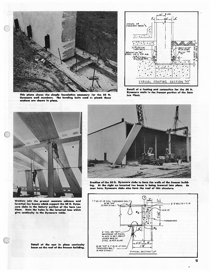
Detail of the cast in place continuitybeam on the roof of the freezer building.
Detail of a footing and connection for the 50 ft.Dynacore walls in the freezer portion of the SaraLee Plant.
Erection of the 50 ft. Dynacore slabs to form the walls of the freezer building. At the right an inverted toe beam is being lowered into place. Asseen here, Dynacore slabs also form the roof of this structure.
This photo shows the simple foundation necessary for the 50 ft.Dynacore wall members. The leveling bolts used to plumb thesesections are shown In place.
TYPICRL FOOTING SECTION FF’
t7-—
- -
Welders join the precast concrete columns andinverted toe beams which support the 50 ft. Dynacore slabs in the bakery portion of the Sara LeePlant. Note the holes in the inverted tees whichgive continuity to the Dynacore voids.
1”0i! 0 BOLTS X li_a!
FORMBOARO
5

RIGID FRAME PRESTRESSED BRIDGE WINS ARCHITECTURAL AWARDWith a remarkable consideration
for aesthetics the City of Oakland, Cal.ifornia developed the sweeping curvedbridge of prestressed concrete illustrated on the cover. Oakland wanted abridge that would provide a lift to therather drab surroundings of its industrial site. The solution was produced bythe team of Kaiser Engineers; T. Y. Linand Associates International, ConsultingStructural Engineers; and ArchitectJohn Carl Warnecke & Associates.
Several methods of construction wereconsidered including cast-in-place concrete, composite steel girders, and prestressed concrete. The type of construction finally accepted for the 1,000 ft.long bridge employed curved prestressed concrete arched girders.
The four main spans, where the bridgecrosses the railroad tracks, are 165 feetlong. The prestressed girders taper intothe piers forming a graceful sculpturedappearance.
Besides being an architectural break.through in bridge construction thisstructure also produced some unusualand creative thinking in the applicationof prestressed concrete. The bridge represents perhaps the first rigid frame,three dimensionally prestressed, bridgeever built in North America.
The bridge must of course be startlingto those who cannot perceive of a curvedprestressed concrete structure. This isactually a relatively simple matter sinceby placing a concentric prestress forceon a curved member it doesn’t realizeit is curved and each section goes aboutits business carrying the load. Loads oncurved members do however, induce torsion stresses which must be considered.
In order to carry these loads thebridge was post-tensioned three dimensionally. At each pier transverse andvertical prestress forces were applied.These forces enabled the pier to carrythe large horizontal and vertical bendingmoments induced by the direct, torsional, and eccentric loads. The 6 ft. deepcurved beams were of course prestressedlongitudinally and some of this forcewas carried into the haunched pier tocomplete the rigid frame. This completed the three dimensional prestress.ing.
Another interesting innovation in prestressing this structure, is that it wasalso externally prestressed in order tocompensate for the creep and shrinkagestresses and losses set up in this largecast-in-place structure. This was accomplished with hydraulic jacks by jackingagainst each abutment.
The bridge is now under constructionand the piers and foundations have beencompleted.6
In keeping with the emphasis on attractive appearance, white cement willbe used for the concrete and plasticforms will be used to produce a smoothfinish. Another interesting innovationwas the placing of the lighting luminaires in the handrails insuring a cleansilhouette for the bridge.
City officials explained prestressedconcrete was selected over other concepts involving other materials becauseof lower initial cost plus low maintenance.
The bridge was selected by Progressive Architecture magazine hi theirTenth Annual Design Awards programas winner of a citation based on design.
pSI
SpC
r,
U
ftC)
wtt
St
l(
ti
11
bC
p
5
C
S
IC
Rendering of the 165 ft. Curved PrestressedSpans and the Double Curved Piers.
Detail of post-tensioned hinge at typi.cal pier.
Detail of post-tensioned cable profileand one of the two expansion jointsin the bridge.
I
Pier and curb section showing handrail illumination and Curved Pier Configuration. I

D Prestressed Railroad BridgeEmploys I.atest
(\ AREA Standards
At La Junta, Colorado, a new 4-span,prestressed concrete bridge is under construction for the Atchison, Topeka andSanta Fe Railroad. This structure replaces an old timber trestle and willcarry a three track main line on therailroad.
The latest AREA specifications wereused to design this new bridge whichfeatures 28 ft. 0 in. long prestressed concrete box beams 27 in. deep and 42 in.wide. These beams are voided and pretensioned with 29.7/16 in. strands. Thestructure has been designed for E.65 liveload plus 335% impact.
The bridge is being built under onetrack at a time to minimize rail trafficinterruptions. The north track is nowbeing carried over the new prestressed
— concrete structure and pile driving isproceeding on the center track.
Twenty inch square precast pre.stressed concrete piling is first drivendown through the existing timber trestlestructure. Then continuous caps are castin place to form 9-pile bents. The boxgirders are placed on these caps and
• cushioned by butyl bearing pads of 60-
O 70 durometer. Steel rods of 11/4” diameter are inserted transversely into thebeams and tightened so that the boxgirders fit snuggly up against each other.The shear keys are filled with an expand.ing cement grout to bond the deck members together and to distribute the loadbetween the girders.
— The deck is then covered with a 1/16in. butyl membrane and 1,4 in. thickasphalt impregnated sheets. Standard
railroad methods are used to ballast thebridge.
A great many bids were received fromprestressed concrete manufacturersthroughout the territory serviced by theSanta Fe. Atlas Structural Concrete Incorporated at El Paso, Texas fabricatedthe box beams and the piling was manufactured by Martin Marietta of Albuquerque, N M.
No newcomer to the field of prestressed concrete construction, the A T &S F has built two previous bridges of thismaterial. The first was a post-tensionedstructure at the U.S. Air Force Academyin Colorado Springs, Colorado and thesecond was a pretensioned bridge installed near San Bernardino, California.The use of other prestressed concretestructures is planned.
The prestressed beams were placed forone track at a time to eliminate railtraffic interruptions. The Santa Feplaced the first 16 beams in 1 ‘/2 days.
In this photo the third span of box beams Isbeing placed. Caps for this bridge were castin place. Note the prestressed concrete pilingthat was driven through the existing timbertrestle.
Unloading new prestressed concrete box girders at A T & S F bridge site, La Junta,Colorado. The 28 ft. beams are 27 in. deep and 42 in. wide.
7

500 F+. MedwayBridge SpanComple+ed
The 100 ft. drop-in-girders have beenplaced between the two 200 ft. cantileverarms to complete the 500 ft. main spanof the Medway bridge in England. Thebridge with its approach spans has anoverall length of 3,272 ft. 6 in. Thereare three spans over the river: the 500ft. center span, and two side spans of312 ft. 6 in. each. These three spanswere built by the spectacular cantilevermethod. The cantilever method employsself supporting formwork.
Placing a 100 ft. drop-in-girder to complete the 500 ft. span of the MedwayBridge.
205 W. WACKER DRIVE
CHICAGO 6, ILLINOIS
PCI PROFESSIONAL MEMBERCO-AUTHORS NEW BOOK
ON PRESTRESSED CONCRETEDr. P. W. Abeles, PCI Professional
Member and F. H. Turner have recentlywritten a book entitled, “PrestressedConcrete Designer’s Handbook.” TheDesigner’s Handbook is published byDartmouth Publications, Limited ofLondon.
In this work the authors have discussed in detail, methods of prestress.ing, materials, behavior of prestressedbeams, permissible stress, end blocks,applications, and a host of other subjectsnecessary to every prestressed concretedesigner. The Designer’s Handbook iswell illustrated with line drawings andcharts. A lengthy discussion and analysis of statically indeterminate structures•is also presented in the text
Dr. Abeles is the author of severalbooks and papers on prestressed concrete design and engineering, many ofwhich have been published in the Journal of the Prestressed Concrete Institute.He also gave an excellent presentationat the 1962 PCI Annual Convention inNew Orleans which is being published inthe February issue of the PCI Journal.
MEMBERSHIP APPLICATIONSAPPROVED BY
BOARD OF DIRECTORS
SIPOREX COMPANY(Division of Domtar Construction
Mati. Ltd.)P.O. Box 216 Station “F”50 Maitland StreetToronto 5, Canada
PROFESSIONAL
GERALD C. BELANGER3540 Maplewood #202Montreal, Quebec, Canada
ALFRED BUMANIS273 E. Village DriveNorthialce, Illinois
BENNETT FEINSILBER1937 Tenbroeck Ave.New York 61, N. Y.
ALEX L. JACOBUS311 North Tracy St.Wichita 12, Kansas
CARL B. JOHNSON800 West Colorado Blvd.Los Angeles 41, California
LELAND L. LAWRENCE JR.5725 E. Hawthorne St.Tucson, Arizona
HUGH N. C. MONCKTONP.O. Box 132Hamilton, New Zealand
SVEND H. NIELSEN2039 Eighth StreetRiverside, California
AFFILIATE
MIGUEL BOZZOUniversidad Nacional De IngenieriaApartado 1301Lima, Peru, S.A.
GORDON V. HUGELIER117 Euclid Ave.Leesburg, Florida
GAMI RAMESH C.1114 BertrandManhattan, Kansas State
STUDENT
YUK.SHING CHAN50 Fruit StreetWorcester, Mass.
JORGE GARCIA SUAREZPuente Monagas a TajamarEd. Tajaniar Apt. 12Caracas, Venezuela
CORRECTIONSThe prestressed concrete pile standardsmentioned in the December issue weredeveloped by a Joint Committee of theAmerican Association of State HighwayOfficials and P.C.I.
The consulting engineers for the Humble Oil Parking Garage were Stacy &Skinner, Los Angeles.
-
0
The bridge is composed of 3 monolithic box beanis which are cast in 10 ft.long increments. The individual 10 ft.elements are post-tensioned to the onespreviously cast and thus the span is corn- ACTIVEpleted much like a horizontal slip form.The only construction supports usedwere two steel towers which carried portions of the 312 ft. 6 in. spans. This wasnecessary because the shorter 200 ft.arm of the river span was of course toolight to counterbalance the longer approach span.
The bridge is being constructed as twoseparate side by side structures.
PPSTPESSED COfPjE INSflTUTE
Return Requested
—.,