centrally prestressed unreinforced concrete columns and · pdf filecentrally prestressed...
TRANSCRIPT
CENTRALLY PRESTRESSED UNREINFORCED CONCRETE COLUMNS AND PILES
D. V. Reddy*, Florida Atlantic University, USA
R. Periyaiah, Sea Engineering Inc., USA
28th Conference on OUR WORLD IN CONCRETE & STRUCTURES: 28 - 29 August 2003, Singapore
Article Online Id: 100028048
The online version of this article can be found at:
http://cipremier.com/100028048
This article is brought to you with the support of
Singapore Concrete Institute
www.scinst.org.sg
All Rights reserved for CI‐Premier PTE LTD
You are not Allowed to re‐distribute or re‐sale the article in any format without written approval of
CI‐Premier PTE LTD
Visit Our Website for more information
www.cipremier.com
28th Conference on OUR WORLD IN CONCRETE & STRUCTURES: 28 - 29 August 2003, Singapore
CENTRALLY PRESTRESSED UNREINFORCED CONCRETE COLUMNS AND PILES
Abstract:
D. V. Reddy*, Florida Atlantic University, USA R. Periyaiah, Sea Engineering Inc., USA
It has been observed that the compressive resistance of axially loaded reinforced concrete components is invariably less than the sum of individual strengths of the constituent concrete and steel elements due to structural incompatibility in the inelastic phase. Structural instability, at or near ultimate limit states in traditionally reinforced concrete columns, renders accurate prediction of their resistance to be difficult. This unreliability, exacerbated by the fact that loading of columns without eccentricity is practically impossible, causes design codes to specify severe resistance factors in order to assure a desirable safety level. Structural reliability is further impaired by the probability of spalling of the concrete cover due to corrosion of the reinforcement.
A series of tests were carried out in which the performance of the "Centrally Prestressed Unreinforced Concrete" (CPUC) column was compared with that of traditionally constructed bridge piers and piles. The CPUC column design is an innovative idea, by which the innate incompatibility between concrete and steel is eliminated by removal of the latter; but flexural resistance and ductility are restored by the application of a centrally located prestressing tendon or closely spaced strands. This concentration of steel results in a significant increase in concrete cover for better corrosion protection without loss in strength.
The practical applicability of the CPUC column design concept is substantiated by an inelastic analysis. CPUC column test results are compared with those for traditional reinforced concrete and prestressed concrete columns.
Columns fitted out with modified Freyssinet hinges, with which the central prestressing tendon is structurally compatible, allow a control, especially for earthquakes, for the eccentricity of axial forces. The second phase deals with an energy absorbing device compatible with the CPUC column to meet the occasional high ductility demand of the CPUC columns in earthquake conditions. Hinges were tested for compressive strength and moment-rotation capability. Parametric studies of the hinges were conducted for different filler materials, and width-to-height ratios. The confined filler material in the Freyssinet type hinge was found to have excellent compressive strength and moment-rotation capability. The parameters, width-to-height ratios and different filler materials, had significant effect on the hinge's performance.
421
Introduction
Reinforced concrete structures have been widely used in past years due to their composition of slender, lighter, and longer span members with increased flexural capacity, energy absorption capacity, and resilience.
Increased concerns about the application of reinforced concrete members as compression members, especially in corrosive and seismic environments, has been expressed by many researchers and practicing engineers. The basic concerns are its inherent material nonhomogenity, corrodable rebar's traditional perimetrical location, and column beam connections. The increase in airborne corrosive chemicals and percolation of salt laden water causes corrosion of the reinforcement. The cracks formed along the rebars due to corrosion tend to reduce the effective area of the column and the degree of restraint that the covering concrete provides to the steel bars, thus reducing column strength. This reduction has been reported up to 30%, Domoto and Misra (1988).
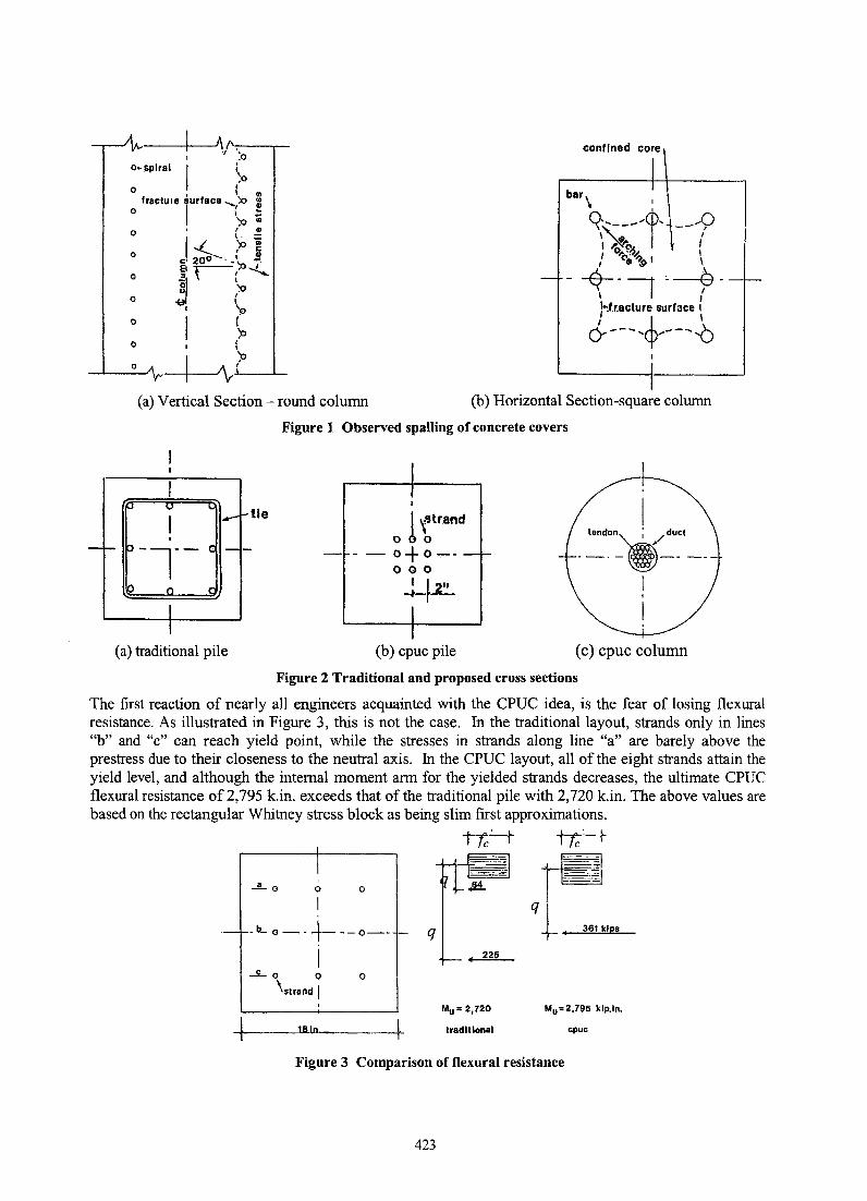
Many investigators are undergoing studies of the corrosion problem and viable remedies for reinforced concrete bridge columns. Investigators Uomoto and Misra (1988), and Ranade and Reddy (1994) recommended that the increase of the concrete cover is effective in solving the corrosion problem in reinforced concrete columns. However, the increased concrete cover leads to the potential structural instability of reinforced concrete column due to reduction in effective confined area. The tendency of ties bending outward, the arching action between steel bars, and the reduction in the effectively confined sectional area, Figure 1, leading to reduction in strength and ductility, was identified by Sheikh and Uzumeri (1980), Mander, Priestley, and Park (1988), and Cusson and Paultre (1994). Razvi and Saatcioglu (1994) indicated that effective confinement can be improved by closer ties, but this increases the susceptibility of cover separation. Ichinose (1996) pointed out that reversed cyclic loading often causes splitting bond failure in reinforced concrete columns.
On the other hand, Zia and Moreadith (1966) concluded that prestressed columns and piles, especially those subjected to large load eccentricity, offer high strength and ductility. Elias and Durrani (1988) and Carinci and Halvorsen (1987) reported that lateral reinforcement does not have any effect on the load carrying capacity of prestressed columns, and recommended elimination of the 0.85 strength reduction factor, since the concrete in such columns without ties is able to reach its theoretical ultimate strength value. One cumulative argument that can be derived from these studies is that the good performance of prestressed concrete columns is not conditional upon the presence of ties.
In fact, as the prestressing strands are in a state of high axial tension (approximately 6,000 microstrain), there is no possibility of premature strand buckling as the concrete approaches failure (approximately 3,600 microstrain). But, the elimination of ties or spirals does not resolve the corrosion problem of the strands. The first innovative idea of this project is the relocation of all prestressing strands into a central location by which the concrete cover is increased to the possible maximum. Typical cross sections of the centrally prestressed unreinforced concrete (CPUC) piles and columns are displayed in Figure 2. For the same level of prestress, the strands of the traditional pile design are simply moved into a central 2.0 in. grid pattern, similar to beams, and without ties. In the CPUC column, the strands are banded into a posttensioning tendon, located in a central duct. The tendon can be loop-anchored in the substructure and the post-tensioning is carried out from the top of the superstructure, thus connecting the three components together.
422
I ~ f\-.,-. ---..-I 'l:O
o~ ,spiral I : ~o
o , {m o fraclule surface ..... :O !
o
o
o
o
o
o
I ( .. '::0 CIl
I "-- ~~ ~ c 200-- .• ' S, ~ -r--,'p-..l.... j ;»
I '0 ,. \
P , , ~
~ ___ O-/\N_~~~~/ __ ~
confined core
I
I (a) Vertical Section - round column (b) Horizontal Section-square column
tie
(a) traditional pile
Figure 1 Observed spalling of concrete covers
I ,'Jtrand o b 0
-- 0+ 0--000
-L~
(b) cpuc pile
I landon~duct
.-.-~---.-
I I
I (c) cpuc column
Figure 2 Traditional and proposed cross sections
The first reaction of nearly all engineers acquainted with the CPUC idea, is the fear of losing flexural resistance. As illustrated in Figure 3, this is not the case. In the traditional layout, strands only in lines "b" and "c" can reach yield point, while the stresses in strands along line "a" are barely above the prestress due to their closeness to the neutral axis. In the CPUC layout, all of the eight strands attain the yield level, and although the internal moment arm for the yielded strands decreases, the ultimate CPUC flexural resistance of 2,795 k.in. exceeds that of the traditional pile with 2,720 k.in. The above values are based on the rectangular Whitney stress block as being slim first approximations.
I
I , o ....Lo o
-r-IL 0-.4---0--
..5.- 0 0
'strand I o
,
~ ___ 1~8~ln~ ___ ~_
q
tTc-' f iTc:·- t-
• 225
Mu ·2,720
traditional
~, ---
I~ q t I 361 kips
Mu=2,795 klp.ln.
cpuc
Figure 3 Comparison of flexural resistance
423
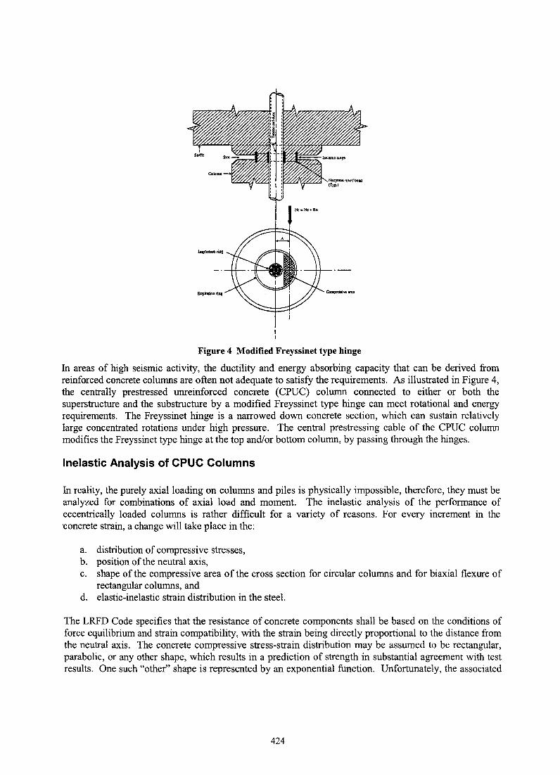
Figure 4 Modified Freyssinet type hinge
In areas of high seismic activity, the ductility and energy absorbing capacity that can be derived from reinforced concrete columns are often not adequate to satisfy the requirements. As illustrated in Figure 4, the centrally prestressed unreinforced concrete (CPUC) column connected to either or both the superstructure and the substructure by a modified Freyssinet type hinge can meet rotational and energy requirements. The Freyssinet hinge is a narrowed down concrete section, which can sustain relatively large concentrated rotations under high pressure. The central prestressing cable of the CPUC column modifies the Freyssinet type hinge at the top and/or bottom column, by passing through the hinges.
Inelastic Analysis of CPUC Columns
In reality, the purely axial loading on columns and piles is physically impossible, therefore, they must be analyzed for combinations of axial load and moment. The inelastic analysis of the performance of eccentrically loaded columns is rather difficult for a variety of reasons. For every increment in the 'concrete strain, a change will take place in the:
a. distribution of compressive stresses, b. position of the neutral axis, c. shape of the compressive area of the cross section for circular columns and for biaxial flexure of
rectangular columns, and d. elastic-inelastic strain distribution in the steel.
The LRFD Code specifies that the resistance of concrete components shall be based on the conditions of force equilibrium and strain compatibility, with the strain being directly proportional to the distance from the neutral axis. The concrete compressive stress-strain distribution may be assumed to be rectangular, parabolic, or any other shape, which results in a prediction of strength in substantial agreement with test results. One such "other" shape is represented by an exponential function. Unfortunately, the associated
424
numerical process was so cumbersome and inaccurate that it was not accepted for engineering applications in spite of the fact that it seems to offer the best correlation with test results.
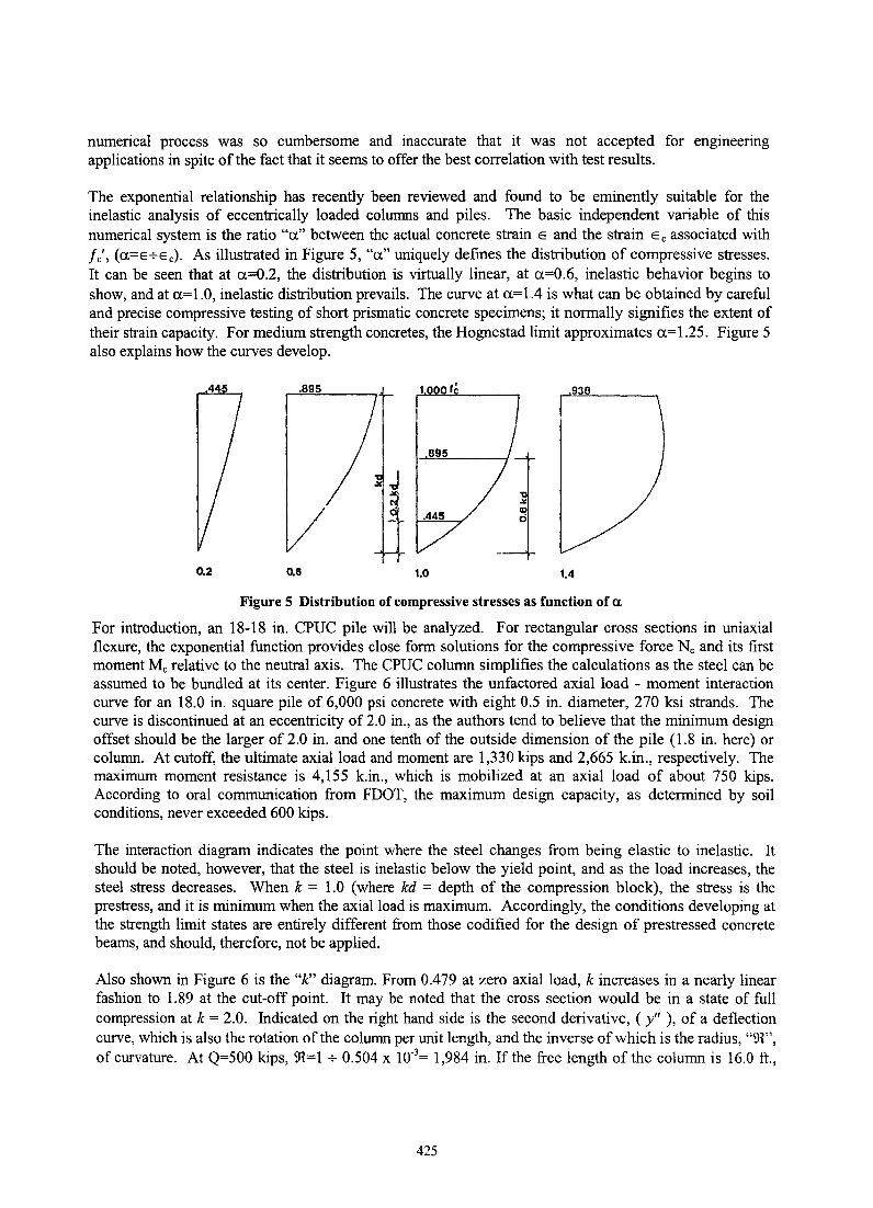
The exponential relationship has recently been reviewed and found to be eminently suitable for the inelastic analysis of eccentrically loaded columns and piles. The basic independent variable of this numerical system is the ratio "a." between the actual concrete strain E and the strain Ee associated with fe', (a.=E+Ee). As illustrated in Figure 5, "a." uniquely defines the distribution of compressive stresses. It can be seen that at 0.=0.2, the distribution is virtually linear, at 0.=0.6, inelastic behavior begins to show, and at 0.=1.0, inelastic distribution prevails. The curve at 0.=1.4 is what can be obtained by careful and precise compressive testing of short prismatic concrete specimens; it normally signifies the extent of their strain capacity. For medium strength concretes, the Hognestad limit approximates 0.=1.25. Figure 5 also explains how the curves develop.
.93B
.445
0.2 0.6 1.0 1.4
Figure 5 Distribution of compressive stresses as function of a.
For introduction, an 18-18 in. CPUC pile will be analyzed. For rectangular cross sections in uniaxial flexure, the exponential function provides close form solutions for the compressive force Ne and its first moment Me relative to the neutral axis. The CPUC column simplifies the calculations as the steel can be assumed to be bundled at its center. Figure 6 illustrates the unfactored axial load - moment interaction curve for an 18.0 in. square pile of 6,000 psi concrete with eight 0.5 in. diameter, 270 ksi strands. The curve is discontinued at an eccentricity of 2.0 in., as the authors tend to believe that the minimum design offset should be the larger of 2.0 in. and one tenth of the outside dimension of the pile (1.8 in. here) or column. At cutoff, the ultimate axial load and moment are 1,330 kips and 2,665 k.in., respectively. The maximum moment resistance is 4,155 k.in., which is mobilized at an axial load of about 750 kips. According to oral communication from FDOT, the maximum design capacity, as determined by soil conditions, never exceeded 600 kips.
The interaction diagram indicates the point where the steel changes from being elastic to inelastic. It should be noted, however, that the steel is inelastic below the yield point, and as the load increases, the steel stress decreases. When k = 1.0 (where kd = depth of the compression block), the stress is the prestress, and it is minimum when the axial load is maximum. Accordingly, the conditions developing at the strength limit states are entirely different from those codified for the design of prestressed concrete beams, and should, therefore, not be applied.
Also shown in Figure 6 is the "k" diagram. From 0.479 at zero axial load, k increases in a nearly linear fashion to 1.89 at the cut-off point. It may be noted that the cross section would be in a state of full compression at k = 2.0. Indicated on the right hand side is the second derivative, (y" ), of a deflection curve, which is also the rotation of the column per unit length, and the inverse of which is the radius, "~", of curvature. At Q=500 kips, ~=1 + 0.504 x lO·3= 1,984 in. If the free length of the column is 16.0 ft.,
425
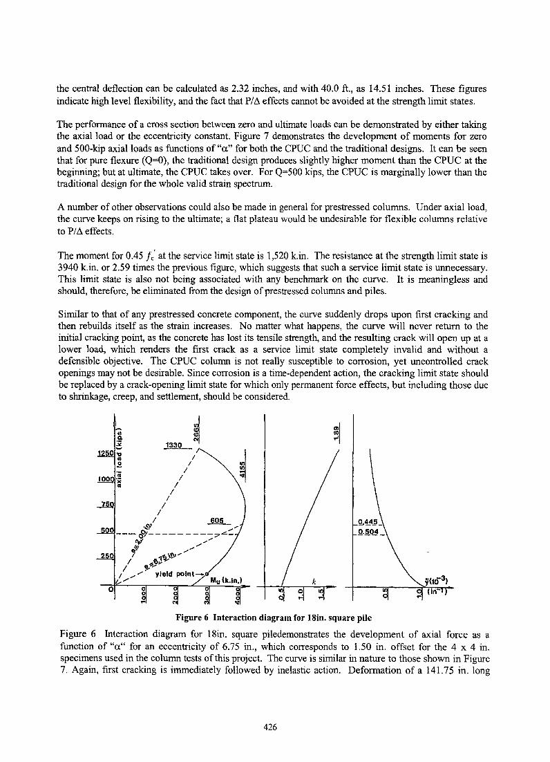
the central deflection can be calculated as 2.32 inches, and with 40.0 ft., as 14.51 inches. These figures indicate high level flexibility, and the fact that P/~ effects cannot be avoided at the strength limit states.
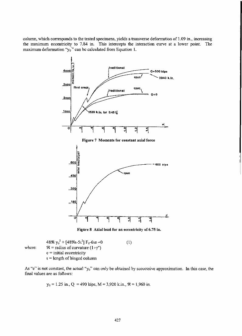
The performance of a cross section between zero and ultimate loads can be demonstrated by either taking the axial load or the eccentricity constant. Figure 7 demonstrates the development of moments for zero and 500-kip axial loads as functions of "a" for both the CPUC and the traditional designs. It can be seen that for pure flexure (Q=O), the traditional design produces slightly higher moment than the CPUC at the beginning; but at ultimate, the CPUC takes over. For Q=500 kips, the CPUC is marginally lower than the traditional design for the whole valid strain spectrum.
A number of other observations could also be made in general for prestressed columns. Under axial load, the curve keeps on rising to the ultimate; a flat plateau would be undesirable for flexible columns relative to P/~ effects.
The moment for 0.45 fe' at the service limit state is 1,520 k.in. The resistance at the strength limit state is 3940 k.in. or 2.59 times the previous figure, which suggests that such a service limit state is unnecessary. This limit state is also not being associated with any benchmark on the curve. It is meaningless and should, therefore, be eliminated from the design of prestressed columns and piles.
Similar to that of any prestressed concrete component, the curve suddenly drops upon first cracking and then rebuilds itself as the strain increases. No matter what happens, the curve will never return to the initial cracking point, as the concrete has lost its tensile strength, and the resulting crack will open up at a lower load, which renders the first crack as a service limit state completely invalid and without a defensible objective. The CPUC column is not really susceptible to corrosion, yet uncontrolled crack openings may not be desirable. Since corrosion is a time-dependent action, the cracking limit state should be replaced by a crack-opening limit state for which only permanent force effects, but including those due to shrinkage, creep, and settlement, should be considered.
Figure 6 Interaction diagram for lSin. square pile
Figure 6 Interaction diagram for 18in. square piledemonstrates the development of axial force as a function of "a" for an eccentricity of 6.75 in., which corresponds to 1.50 in. offset for the 4 x 4 in. specimens used in the column tests of this project. The curve is similar in nature to those shown in Figure 7. Again, first cracking is immediately followed by inelastic action. Deformation of a 141.75 in. long
426
column, which corresponds to the tested specimens, yields a transverse deformation of 1.09 in., increasing the maximum eccentricity to 7.84 in. This intercepts the interaction curve at a lower point. The maximum deformation ''yo'" can be calculated from Equation 1.
where:
0=500 kips ~--;I'--'-......
cpuc 3940 k.ln.
0=0 2000
1000
Figure 7 Moments for constant axial force
R B
600 -g .2 ii i
450
300
150
~_--·-605 kips
Figure 8 Axial load for an eccentricity of 6.75 in.
4891 Yo2 + [4891t-5l,z] Fo-6te =0 91 = radius of curvature (1 +y") e = initial eccentricity t = length of hinged column
(1)
As "e" is not constant, the actual "Yo" can only be obtained by successive approximation. In this case, the final values are as follows:
Yo = 1.25 in., Q = 490 kips, M = 3,920 k.in., 91 = 1,960 in.
427
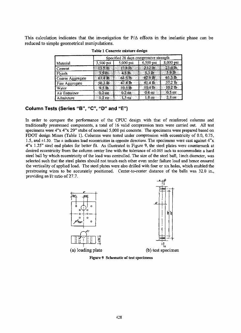
This calculation indicates that the investigation for PI ~ effects in the inelastic phase can be reduced to simple geometrical manipulations.
Table 1 Concrete mixture design
Material
Air Entrainer 0.502:
Admixture 2.1oz
Column Tests (Series "B", "e", "0" and "E")
In order to compare the performance of the CPUC design with that of reinforced columns and traditionally prestressed components, a total of 16 valid compression tests were carried out. All test specimens were 4"x 4"x 29" stubs of nominal 5,000 psi concrete. The specimens were prepared based on FDOT design Mixes (Table 1). Columns were tested under compression with eccentricity of 0.0, 0.75, 1.5, and ±l.SO. The ± indicates load eccentricities in opposite directions. The specimens were cast against 4"x 4"x 1.25" steel end plates for better fit. As illustrated in Figure 9, the steel plates were countersunk at desired eccentricity from the column center line with the tolerance of ±O.OOS inch to accommodate a hard steel ball by which eccentricity of the load was controlled. The size of the steel ball, linch diameter, was selected such that the steel plates should not touch each other even under failure load and hence ensured the verticality of applied load. The steel plates were also drilled with four or six holes, which enabled the prestressing wires to be accurately positioned. Center-to-center distance of the balls was 32.0 in., providing an lIr ratio of 27.7.
i 10 (a) loading plate (b) test specimen
Figure 9 Schematic of test specimens
428
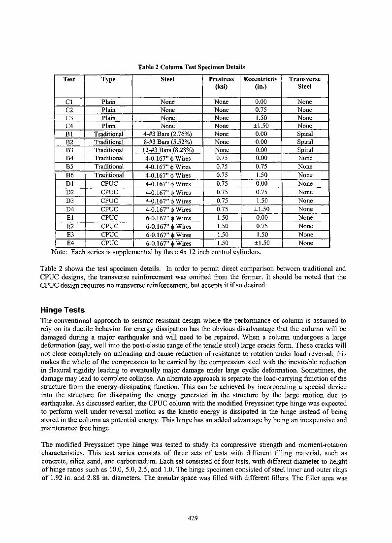
Table 2 Column Test Specimen Details
Test Type Steel Prestress Eccentricity Transverse (ksi) (in.) Steel
Cl Plain None None 0.00 None C2 Plain None None 0.75 None C3 Plain None None 1.50 None C4 Plain None None ±1.50 None Bl Traditional 4-#3 Bars (2.76%) None 0.00 Spiral B2 Traditional 8-#3 Bars (5.52%) None 0.00 Spiral B3 Traditional 12-#3 Bars (8.280/<>1 None 0.00 Spiral B4 Traditional 4-0.167" Ij> Wires 0.75 0.00 None B5 Traditional 4-0.167" Ij> Wires 0.75 0.75 None
B6 Traditional 4-0.167" Ij> Wires 0.75 1.50 None
01 CPUC 4-0.167" Ij> Wires 0.75 0.00 None 02 CPUC 4-0.167" Ij> Wires 0.75 0.75 None 03 CPUC 4-0.167" Ij> Wires 0.75 1.50 None 04 CPUC 4-0.167" <!> Wires 0.75 ±1.50 None El CPUC 6-0.167" <!> Wires 1.50 0.00 None E2 CPUC 6-0.167" <!> Wires 1.50 0.75 None E3 CPUC 6-0.167" q, Wires 1.50 1.50 None E4 CPUC 6-0.167" <!> Wires 1.50 ±1.50 None
Note: Each senes IS supplemented by three 4x 12 mch control cylmders.
Table 2 shows the test specimen details. In order to permit direct comparison between traditional and CPUC designs, the transverse reinforcement was omitted from the former. It should be noted that the CPUC design requires no transverse reinforcement, but accepts it if so desired.
Hinge Tests The conventional approach to seisnUc-resistant design where the performance of column is assumed to rely on its ductile behavior for energy dissipation has the obvious disadvantage that the column will be damaged during a major earthquake and will need to be repaired. When a column undergoes a large deformation (say, well into the post-elastic range of the tensile steel) large cracks form. These cracks will not close completely on unloading and cause reduction of resistance to rotation under load reversal; this makes the whole of the compression to be carried by the compression steel with the inevitable reduction in flexural rigidity leading to eventually major damage under large cyclic deformation. Sometimes, the damage may lead to complete collapse. An alternate approach is separate the load-carrying function of the structure from the energy-dissipating function. This can be achieved by incorporating a special device into the structure for dissipating the energy generated in the structure by the large motion due to earthquake. As discussed earlier, the CPUC column with the modified Freyssinet type hinge was expected to perform well under reversal motion as the kinetic energy is dissipated in the hinge instead of being stored in the column as potential energy. This hinge has an added advantage by being an inexpensive and maintenance free hinge.
The modified Freyssinet type hinge was tested to study its compressive strength and moment-rotation characteristics. This test series consists of three sets of tests with different filling material, such as concrete, silica sand, and carborundum. Each set consisted of four tests, with different diameter-to-height of hinge ratios such as 10.0,5.0,2.5, and 1.0. The hinge specimen consisted of steel inner and outer rings of 1.92 in. and 2.88 in. diameters. The annular space was filled with different fillers. The filler area was
429
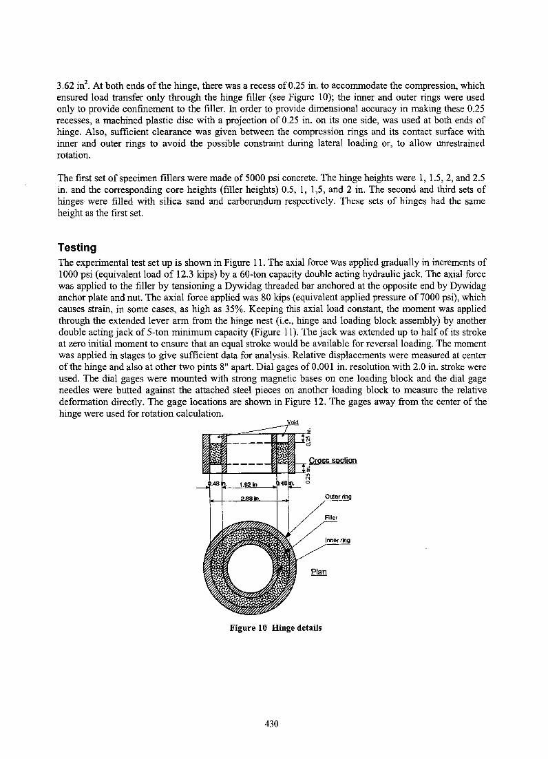
3.62 in2• At both ends of the hinge, there was a recess of 0.25 in. to accommodate the compression, which
ensured load transfer only through the hinge filler (see Figure 10); the inner and outer rings were used only to provide confinement to the filler. In order to provide dimensional accuracy in making these 0.25 recesses, a machined plastic disc with a projection of 0.25 in. on its one side, was used at both ends of hinge. Also, sufficient clearance was given between the compression rings and its contact surface with inner and outer rings to avoid the possible constraint during lateral loading or, to allow unrestrained rotation.
The first set of specimen fillers were made of 5000 psi concrete. The hinge heights were 1, 1.5,2, and 2.5 in. and the corresponding core heights (filler heights) 0.5, 1, 1,5, and 2 in. The second and third sets of hinges were filled with silica sand and carborundum respectively. These sets of hinges had the same height as the first set.
Testing The experimental test set up is shown in Figure 11. The axial force was applied gradually in increments of 1000 psi (equivalent load of 12.3 kips) by a 60-ton capacity double acting hydraulic jack. The axial force was applied to the filler by tensioning a Dywidag threaded bar anchored at the opposite end by Dywidag anchor plate and nut. The axial force applied was 80 kips (equivalent applied pressure of 7000 psi), which causes strain, in some cases, as high as 35%. Keeping this axial load constant, the moment was applied through the extended lever arm from the hinge nest (i.e., hinge and loading block assembly) by another double acting jack of 5-ton minimum capacity (Figure 11). The jack was extended up to half of its stroke at zero initial moment to ensure that an equal stroke would be available for reversal loading. The moment was applied in stages to give sufficient data for analysis. Relative displacements were measured at center of the hinge and also at other two pints 8" apart. Dial gages of 0.001 in. resolution with 2.0 in. stroke were used. The dial gages were mounted with strong magnetic bases on one loading block and the dial gage needles were butted against the attached steel pieces on another loading block to measure the relative deformation directly. The gage locations are shown in Figure 12. The gages away from the center of the hinge were used for rotation calculation.
Figure 10 Hinge details
430
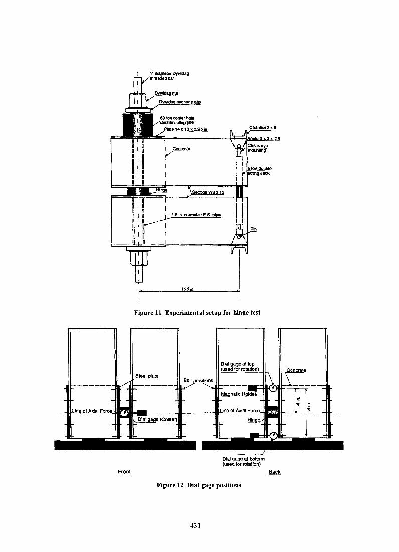
16.Sin.
Figure 11 Experimental setup for hinge test
Dial gage at bottom (used for rotation)
Figure 12 Dial gage positions
431
Test Results and Discussion
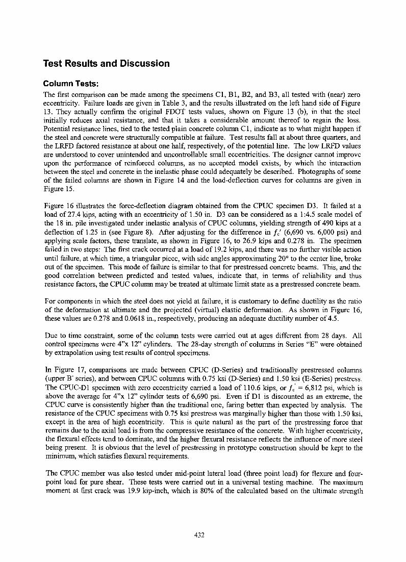
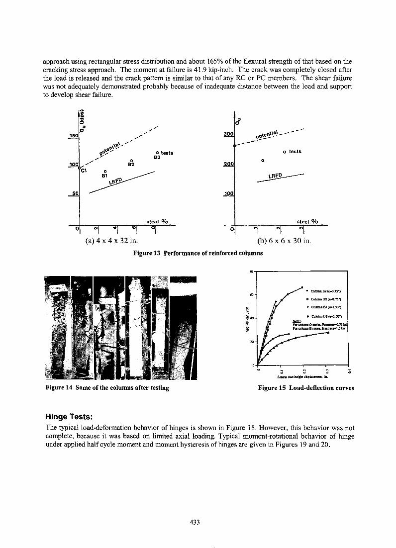
Column Tests: The first comparison can be made among the specimens C1, B1, B2, and B3, all tested with (near) zero eccentricity. Failure loads are given in Table 3, and the results illustrated on the left hand side of Figure 13. They actually confirm the original FDOT tests values, shown on Figure 13 (b), in that the steel initially reduces axial resistance, and that it takes a considerable amount thereof to regain the loss. Potential resistance lines, tied to the tested plain concrete column C1, indicate as to what might happen if the steel and concrete were structurally compatible at failure. Test results fall at about three quarters, and the LRFD factored resistance at about one half, respectively, of the potential line. The low LRFD values are understood to cover unintended and uncontrollable small eccentricities. The designer cannot improve upon the performance of reinforced columns, as no accepted model exists, by which the interaction between the steel and concrete in the inelastic phase could adequately be described. Photographs of some of the failed columns are shown in Figure 14 and the load-deflection curves for columns are given in Figure 15.
Figure 16 illustrates the force-deflection diagram obtained from the CPUC specimen D3. It failed at a load of 27.4 kips, acting with an eccentricity of 1.50 in. D3 can be considered as a 1 :4.5 scale model of the 18 in. pile investigated under inelastic analysis of CPUC columns, yielding strength of 490 kips at a deflection of 1.25 in (see Figure 8). After adjusting for the difference in fe' (6,690 vs. 6,000 psi) and applying scale factors, these translate, as shown in Figure 16, to 26.9 kips and 0.278 in. The specimen failed in two steps: The first crack occurred at a load of 19.2 kips, and there was no further visible action until failure, at which time, a triangular piece, with side angles approximating 20° to the center line, broke out of the specimen. This mode of failure is similar to that for prestressed concrete beams. This, and the good correlation between predicted and tested values, indicate that, in terms of reliability and thus resistance factors, the CPUC column may be treated at ultimate limit state as a prestressed concrete beam.
For components in which the steel does not yield at failure, it is customary to define ductility as the ratio of the deformation at ultimate and the projected (virtual) elastic deformation. As shown in Figure 16, these values are 0.278 and 0.0618 in., respectively, producing an adequate ductility number of 4.5.
Due to time constraint, some of the column tests were carried out at ages different from 28 days. All control specimens were 4"x 12" cylinders. The 28-day strength of columns in Series "E" were obtained by extrapolation using test results of control specimens.
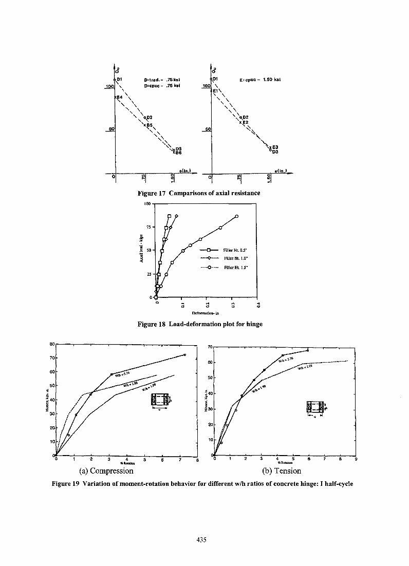
In Figure 17, comparisons are made between CPUC (D-Series) and traditionally prestressed columns (upper B- series), and between CPUC columns with 0.75 ksi (D-Series) and 1.50 ksi (E-Series) prestress. The CPUC-D1 specimen with zero eccentricity carried a load of 110.6 kips, or fe' = 6,812 psi, which is above the average for 4"x 12" cylinder tests of 6,690 psi. Even if D1 is discounted as an extreme, the CPUC curve is consistently higher than the traditional one, faring better than expected by analysis. The resistance of the CPUC specimens with 0.75 ksi prestress was marginally higher than those with 1.50 ksi, except in the area of high eccentricity. This is quite natural as the part of the prestressing force that remains due to the axial load is from the compressive resistance of the concrete. With higher eccentricity, the flexural effects tend to dominate, and the higher flexural resistance reflects the influence of more steel being present. It is obvious that the level of prestressing in prototype construction should be kept to the minimum, which satisfies flexural requirements.
The CPUC member was also tested under mid-point lateral load (three point load) for flexure and fourpoint load for pure shear. These tests were carried out in a universal testing machine. The maximum moment at first crack was 19.9 kip-inch, which is 80% of the calculated based on the ultimate strength
432
approach using rectangular stress distribution and about 165% of the flexural strength of that based on the cracking stress approach. The moment at failure is 41.9 kip-inch. The crack was completely closed after the load is released and the crack pattern is similar to that of any RC or PC members. The shear failure was not adequately demonstrated probably because of inadequate distance between the load and support to develop shear failure.
:;, o
150
o
(a) 4 x 4 x 32 in.
o tests 83
steel 0/0
300
00
o
po~~\!\- --------o tests
o
(b)6x6x30in.
Figure 13 Performance of reinforced columns
M~----------------------'
a CoIumnDl(..o.7S")
• CoIumJI EJ ( ... 1.50")
~ Collmm D3 ( .. 1.50")
; a a d L.al1I1Ii";d.lIdgbtdilp_~ ill.
Figure 14 Some of the columns after testing Figure 15 Load-deflection curves
Hinge Tests: The typical load-deformation behavior of hinges is shown in Figure 18. However, this behavior was not complete, because it was based on limited axial loading. Typical moment-rotational behavior of hinge under applied half cycle moment and moment hysteresis of hinges are given in Figures 19 and 20.
433
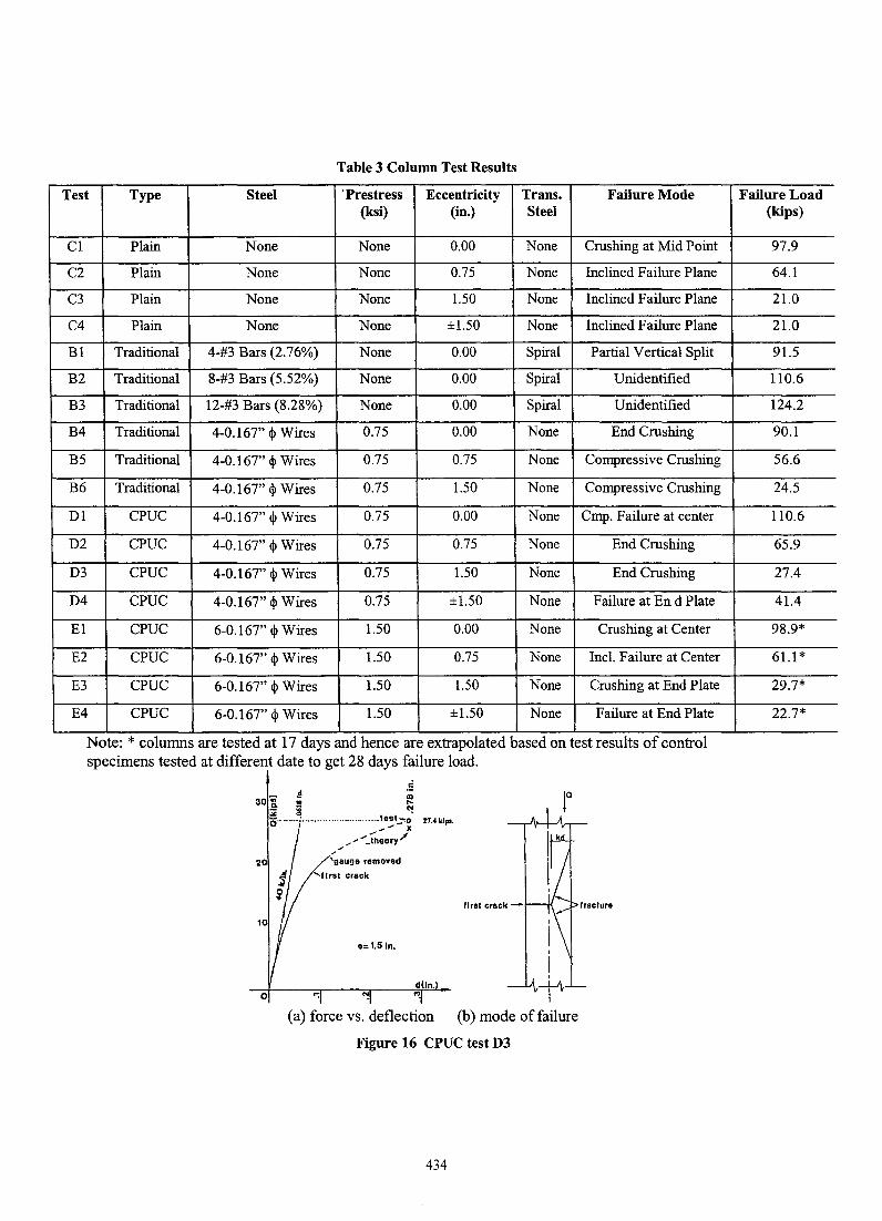
Table 3 Column Test Results
Test Type Steel . Prestress Eccentricity Trans. Failure Mode (ksi) (in.) Steel
Cl Plain None None 0.00 None Crushing at Mid Point
C2 Plain None None 0.75 None Inclined Failure Plane
C3 Plain None None 1.50 None Inclined Failure Plane
C4 Plain None None ±1.50 None Inclined Failure Plane
Bl Traditional 4-#3 Bars (2.76%) None 0.00 Spiral Partial Vertical Split
B2 Traditional 8-#3 Bars (5.52%) None 0.00 Spiral Unidentified
B3 Traditional 12-#3 Bars (8.28%) None 0.00 Spiral Unidentified
B4 Traditional 4-0.167" ~ Wires 0.75 0.00 None End Crushing
B5 Traditional 4-0.167" ~ Wires 0.75 0.75 None Compressive Crushing
B6 Traditional 4-0.167" ~ Wires 0.75 1.50 None Compressive Crushing
Dl CPUC 4-0.167" ~ Wires 0.75 0.00 None Cmp. Failure at center
D2 CPUC 4-0.167" ~ Wires 0.75 0.75 None End Crushing
D3 CPUC 4-0.167" ~ Wires 0.75 1.50 None End Crushing
D4 CPUC 4-0.167" ~ Wires 0.75 ±1.50 None Failure at En d Plate
El CPUC 6-0.167" ~ Wires 1.50 0.00 None Crushing at Center
E2 CPUC 6-0.167" ~ Wires 1.50 0.75 None Incl. Failure at Center
E3 CPUC 6-0.167" ~ Wires 1.50 1.50 None Crushing at End Plate
E4 CPUC 6-0.167" ~ Wires 1.50 ±1.50 None Failure at End Plate
Note: * columns are tested at 17 days and hence are extrapolated based on test results of control specimens tested at different date to get 28 days failure load .
. 5 .!!
30a • :2 ~ ~ ~ 0, .• _ .... ; ............................. le91:0 17.4Idpl •
..... ,- It
,. .................. _theory /
20 gauge removed
flrsl crack
e:1.5 In.
(a) force vs. deflection (b) mode offailure
Figure 16 CPUC test D3
434
fracture
Failure Load (kips)
97.9
64.1
21.0
21.0
91.5
110.6
124.2
90.1
56.6
24.5
110.6
65.9
27.4
41.4
98.9*
61.1 *
29.7*
22.7*
:J a 6 {>1 B.lrad.- .75 ksl Dl E' cpuc - 1.50 kel
00 '\ D'cpuc - .75 ksl 100 , , 84 ' , ' , \
" , , , EI\ '\ , , \ , \
'" , \.02 ',o.e2
'xB5 50 '\ , " ,
'xE2 ", o ,,~
o
" , " '" ''ig~
~,
o
Figure 17 Comparisons of axial resistance
lOO~--------------------------~
75
.e. ... "iI
50 .2
]
25
o<r------r-----~------~----__; o '" .;
DefonnaooD4 in.
~ E3 !D3
eUn)
Figure 18 Load-deformation plot for hinge
B0r----r--~----,---~----~--~----T_--~
70
60
/1'-/
/
20 /
( i :
2 345 <JIo_ (a) Compression
6 1 8
(b) Tension
Figure 19 Variation of moment-rotation behavior for different w/h ratios of concrete hinge: I half-cycle
435
OOr-----r-----.-----r-----.-----.---~
60
40
.520
.§. ... i O~------~~~----~~--~~------~
I -20
-40
·60
-8~L~~~~--L---'---..L--.J6 U cycle Ul cycle
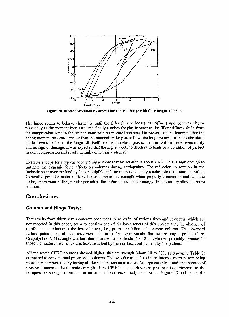
Figure 20 Moment-rotation hysteresis for concrete hinge with filler height of 0.5 in.
The hinge seems to behave elastically :mtil the filler fails or looses its stiffness and behaves elastoplastically as the moment increases, and finally reaches the plastic stage as the filler stiffness shifts from the compression zone to the tension zone with no moment increase. On reversal of the loading, after the acting moment becomes smaller than the moment under plastic flow, the hinge returns to the elastic state. Under reversal of load, the hinge fill itself becomes an e1asto-plastic medium with infinite reversibility and no sign of damage. It was expected that the higher width to depth ratio leads to a condition of perfect triaxial compression and resulting high compressive strength.
Hysteresis loops for a typical concrete hinge show that the rotation is about ± 4%. This is high enough to mitigate the dynamic force effects on columns during earthquakes. The reduction in rotation in the inelastic state over the load cycle is negligible and the moment capacity reaches almost a constant value. Generally, granular materials have better compressive strength when properly compacted and also the sliding movement of the granular particles after failure allows better energy dissipation by allowing more rotation.
Conclusions
Column and Hinge Tests:
Test results from thirty-seven concrete specimens in series 'A' of various sizes and strengths, which are not reported in this paper, seem to confirm one of the basic tenets of this project that the absence of reinforcement eliminates the loss of cover, i.e., premature failure of concrete column. The observed failure patterns in all the specimens of series 'A' approximate the failure angle predicted by Csagoly(1994). This angle was best demonstrated in the slender 4 x 12 in. cylinder, probably because for those the fracture mechanics was least disturbed by the interface confinement by the platens.
All the tested CPUC columns showed higher ultimate strength (about 10 to 20% as shown in Table 3) compared to conventional prestressed columns. This was due to the loss in the internal moment arm being more than compensated by having all the steel in tension at center. At large eccentric load, the increase of prestress increases the ultimate strength of the CPUC column. However, prestress is detrimental to the compressive strength of column at no or small load eccentricity as shown in Figure 17 and hence, the
436
level of prestressing in the prototype construction should be kept to the minimum, which satisfies the flexural requirements.
The failure patterns of CPUC columns were similar to those for conventional prestressed columns reported by Carinci and Halvorsen (1987). The columns failed by sudden crushing in the compression side at about 0.14 times the length from one of the ends. This was followed by diagonal cracking extending to the tension face through the column core. CPUC members under pure flexure (beam bending) and shear loading failed at higher ultimate strengths than those determined analytically. Though these test results clearly evidence the ductility behavior of the CPUC columns, under large deformations like those induced during earthquakes, special devices may be required to dissipate the additional energy stored.
The modified Freyssinet type hinge, called Extended Flexural Device (EFD) for CPUC column, demonstrated excellent energy dissipating characteristics. Test on total of six hinges with three different filler materials and three different height confirmed that the above parameters have definitely affect the moment-rotation performance of the hinges. The moment-rotation behavior of these hinges was similar to that for underreinforced concrete beams in flexure. The filler sustained a strain level of 25,000 psi. Linear behavior was observed up to the strain level of about 4% followed by inelastic behavior up to 8%. The moment-rotation behavior converges to a constant after a few load cycles and survives a number of complete moment reversals without any sign of damage. The moment carrying capacity and compressive strength increase as the width-to-height ratio increases. The harder-granular-filler material showed better performance in terms of moment-rotational and compressive strength capability.
As a whole, the combination of CPUC column and this new hinge seems to be the best alternative for the column in the marine and seismic environment. In addition to the observed increase in compressive strength and ductility, the CPUC columns will provide more corrosion resistance due to large cover and possible better compaction of the concrete (so that high density concrete is possible). The hinges provide extended flexural capacity and over-load protection to the column in seismic conditions. It is possible that the plastic plateau of the curve for hinge can be set at any desired level, i.e. about 75% of the flexural strength of the column, by which the column will not only be protected against both shear and flexural failure due to seismic action, but would also resist the moments generated by gravitational loads without excessive deformation. The observed moment-rotation curve can be modeled bilinearly, i.e., with the rising part pseudo-elastic and the plateau fully inelastic. It considerably reduces the column stiffness and permits easy inelastic design and elimination of the arbitrary strength reduction factor for the column.
ACKNOWLEDGMENT
This paper is based on a National Cooperative Highway Research Program funded project #20-37 "Centrally Prestressed, Unreinforced Concrete Columns and Piles" (Contract Monitor: Dr. K. Thirumalai, P.I.: Dr. D. V. Reddy, and Consultant: P. F. Csagoly). Grateful acknowledgments are due to Paul F. Csagoly, President, Structural Research and Development Engineering, Clearwater, FL, for formulation of the innovative project, participation, and careful monitoring of the investigation. Gratitude is expressed to Dr. K. Thirumalai for his support and encouragement.
437
Bibliography
Carinci, C. A. and Halvorsen, G. T., "Tie Requirements for Prestressed Concrete Columns," PCI Journal, Vol. 32, No.4, July-August 1987, pp.46-79.
Csagoly, P. F., "End effect on the Orientation of the Failure Plane for Compressively Loaded Cylinder and Prismatic Specimens," Unpublished, 1994
Cusson, D. and Paultre, P., "High Strength Columns Confined by Rectangular Ties," Journal of Structural Engineering, ASCE, Vol. 120, No.3, March 1994.
Elias, H. E. and Durrani, A. J., "Confinement of Prestressed Concrete Columns," PCI Journal, Vol.33, No.3, May-June 1988, pp.123-141.
Ichinose, T., "Splitting Bond Failure of RIC Columns under Seismic Action," ACI Structural Journal, Vol. 92, No.5, 1996, pp. 535-542.
Mander, J. B., Priestley, M. J. N., and Park, R., "Theoretical Stress-Strain Model for Confined Concrete," Journal of Structural Engineering, ASCE, Vol. 114, No.8, August 1988.
Ranade, S. and Reddy, D. V., "Computer Modeling for Chloride Diffusion of Reinforced Concrete Beams in the Marine Environment," Proc. International Conf. On Corrosion and Corrosion Protection of Steel in Concrete, Sheffield, England, July 24-28, 1994, pp. 648-657.
Razvi, S. R. and Saatcioglu, M., "Strength and Deformability of Confined High-Strength Concrete Columns," ACI Structural Journal, Vol.91 , No.6, November-December 1994, pp. 678-687.
Sheikh, S. A. and Uzumeri, S. M., "Strength and Ductility of Tied Concrete Columns". Journal of Structural Division, ASCE, Vol. 106, No. ST5, May 1980, pp. 1079-1102.
Uomoto, T. and Misra, S., "Behavior of Concrete Beams and Columns in Marine Environment when Corrosion of Rienforcing Bars takes Place". Proceedings of Second International Conference St. Andrews by-the-Sea, Canada 1988, ACI, SP-109, pp. 127-146.
Zia, P., and Moreadith, F. L., "Ultimate Load Capacity of Prestressed Concrete Columns," ACI Journal, Vol.63, No.7, July 1966, pp. 767-788.
438