fci st75 series flow meters - fluidcomponents.com brochures/flowmeters/st75_st75v... · in mass...
TRANSCRIPT
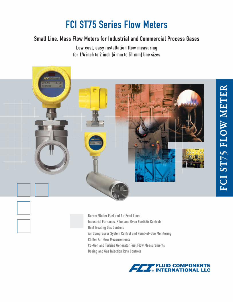
FCI ST75 Series Flow MetersSmall Line, Mass Flow Meters for Industrial and Commercial Process Gases
Low cost, easy installation flow measuring for 1/4 inch to 2 inch [6 mm to 51 mm] line sizes
Burner /Boiler Fuel and Air Feed LinesIndustrial Furnaces, Kilns and Oven Fuel /Air ControlsHeat Treating Gas ControlsAir Compressor System Control and Point-of-Use MonitoringChiller Air Flow MeasurementsCo-Gen and Turbine Generator Fuel Flow MeasurementsDosing and Gas Injection Rate Controls
FCI
ST75
Flo
w M
eTer
ST75 Series Featuresg Direct mass, standard volumetric or standard velocity flow measurement
g Triple outputs: flow rate, temperature & total flow
g Non-clogging, no moving parts
g Wireless IR communications
g 2 line digital display option
g Small, compact design
g Easy installation
g Built-in Vortab® flow conditioning in Model ST75V
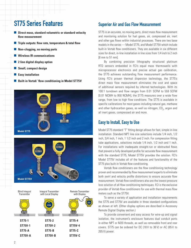
Superior Air and Gas Flow MeasurementST75 is an accurate, no moving parts, direct mass flow measurement and monitoring solution for fuel gases, air, compressed air, inert and other gas flows within industrial processes. There are two base models in the series — Model ST75, and Model ST75V which include built-in Vortab flow conditioners. They are available in six different sizes for direct, in-line installation in line sizes from 1/4 inch to 2 inch [6 mm to 51 mm].
By combining precision lithography structured platinum RTD sensors embedded in FCI’s equal mass thermowells with microprocessor electronics and precise actual gas calibration, the ST75 achieves outstanding flow measurement performance. Using FCI’s proven thermal dispersion technology, the ST75’s direct mass flow measurement eliminates the cost and space of additional sensors required by inferred technologies. With its 100:1 turndown and flow ranges from 0.01 SCFM to 559 SCFM [0.01 NCMH to 950 NCMH], the ST75 measures over a wide flow range, from low to high flow conditions. The ST75 is available in specific calibrations for most gases including natural gas, methane and other hydrocarbon gases, as well as nitrogen, CO2, argon and all inert gases, compressed air and more.
Easy to Install, Easy to UseModel ST75 standard “T” fitting design allows for fast, simple in-line installation. Standard NPT line size selections include 1/4 inch, 1/2 inch, 3/4 inch, 1 inch, 1 1/2 inch and 2 inch. For compression fitting tube applications, selections include 1/4 inch, 1/2 inch and 1 inch. For installations with inadequate straight-run or obstructed flows that prevent a fully developed profile for accurate flow measurement with the standard ST75, Model ST75V provides the solution. FCI’s Model ST75V includes all of the features and functionality of the ST75 plus built-in Vortab flow conditioning.
Vortab flow conditioners are the flow conditioning technology proven and recommended by flow measurement experts to eliminate both swirl and velocity profile distortions to ensure accurate flow measurement. Vortab flow conditioners also are the lowest pressure loss solution of all flow conditioning techniques. FCI is the exclusive provider of Vortab flow conditioners for use with thermal mass flow meters such as the ST75V.
To serve a variety of application and installation requirements the ST75 and ST75V are available in three standard configurations as shown at left. (Other display options are described in Accessory Remote Digital Display section.)
To provide convenient and easy access for wire-up and signal isolation, the instrument’s enclosure features dual conduit ports in either NPT or M20 threads, as well as removable front and rear covers. ST75 can be ordered for DC (18 V to 36 V) or AC (85 V to 265 V) power.
ST75-1 ST75-2 ST75-4
ST75V-1 ST75V-2 ST75V-4
ST75-A ST75-B ST75-C
ST75V-A ST75V-B ST75V-C
Model ST75
Model ST75V
2
Extensive Outputs Assure Application CompatibilityST75 provides the most comprehensive selection of outputs in its class. Dual analog outputs, a pulse output and a digital, serial I/O are all standard.
Dual 4-20 mA analog outputs are field assignable to flow rate and/or temperature. These outputs are user scalable to the instrument’s full calibrated range or any subset. Flow rate is selectable for reading in mass flow or standard volumetric engineering units. Also provided for interface to totalizers is a 0-1000 Hz pulse output of flow.
In all models a standard RS232C serial I/O link is provided for instrument configuration, service/troubleshooting data, and measured readings. Also included in all models is a wireless IR sensor to enable wireless connectivity to PDA devices.
Exclusive Wireless Communications With FCI’s unique new IR link, any Palm-OS based PDA can be used to communicate with the ST75 without contact. This wireless IR link features a password protected, easy-to-follow menu driven program to access all its features. Parameters include measured readings and totalizer values, configuration settings, calibration downloads, diagnostic service codes and more. This wireless interface is ideal to save cost and time when the ST75 will be mounted in a hard to reach location. Requires FCI software accessory kit P/N 019819-01 for the PDA.
Designed and Built to LastST75 will significantly reduce maintenance costs and time. ST75 is a no moving parts design that virtually eliminates the wear out, clogging and excessive pressure drop associated with other flow metering techniques. The sensor element is all-welded stainless steel with Hastelloy-C tips that provide extra protection against invasive conditions within the pipe. The instrument’s electronics are housed in an all-metal, NEMA 4X (IP67) rated enclosure to provide the ruggedness and dust/weather proof protection needed to ensure long-life in industrial and commercial installations.
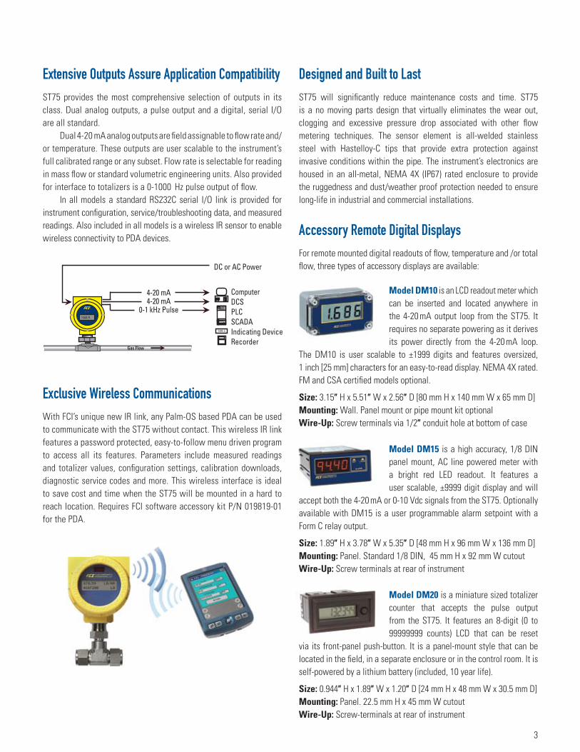
Accessory Remote Digital DisplaysFor remote mounted digital readouts of flow, temperature and /or total flow, three types of accessory displays are available:
Model DM10 is an LCD readout meter which can be inserted and located anywhere in the 4-20 mA output loop from the ST75. It requires no separate powering as it derives its power directly from the 4-20 mA loop.
The DM10 is user scalable to ±1999 digits and features oversized, 1 inch [25 mm] characters for an easy-to-read display. NEMA 4X rated. FM and CSA certified models optional.
Size: 3.15″ H x 5.51″ W x 2.56″ D [80 mm H x 140 mm W x 65 mm D]Mounting: Wall. Panel mount or pipe mount kit optionalWire-Up: Screw terminals via 1/2″ conduit hole at bottom of case
Model DM15 is a high accuracy, 1/8 DIN panel mount, AC line powered meter with a bright red LED readout. It features a user scalable, ±9999 digit display and will
accept both the 4-20 mA or 0-10 Vdc signals from the ST75. Optionally available with DM15 is a user programmable alarm setpoint with a Form C relay output.
Size: 1.89″ H x 3.78″ W x 5.35″ D [48 mm H x 96 mm W x 136 mm D]Mounting: Panel. Standard 1/8 DIN, 45 mm H x 92 mm W cutoutWire-Up: Screw terminals at rear of instrument
Model DM20 is a miniature sized totalizer counter that accepts the pulse output from the ST75. It features an 8-digit (0 to 99999999 counts) LCD that can be reset
via its front-panel push-button. It is a panel-mount style that can be located in the field, in a separate enclosure or in the control room. It is self-powered by a lithium battery (included, 10 year life).
Size: 0.944″ H x 1.89″ W x 1.20″ D [24 mm H x 48 mm W x 30.5 mm D]Mounting: Panel. 22.5 mm H x 45 mm W cutoutWire-Up: Screw-terminals at rear of instrument
3
ST75 Series Flow Meter General SpecificationsInstrumentg Media: Air, compressed air, nitrogen, oxygen, argon, CO2,
ozone, other inert gases, natural gas, other hydrocarbon gases, and hydrogen
g Pipe/Line Size Compatability: 1/4″ to 2″ [6 mm to 51 mm] g Range 1
NPT Line Size: Min. Min. Max. Max. SCFM [NCMH] SCFM [NCMH] 1/4″ 0.04 [0.07] 17.34 [29.47]1/2″ 0.13 [0.22] 50.64 [86.04]3/4″ 0.22 [0.38] 88.88 [151.00]1″ 0.35 [0.59] 139.95 [237.78]1 1/2″ 0.85 [1.44] 339.31 [576.48]2″ 1.40 [2.38] 559.27 [950.20]
Tubing Line Size: Min. Min. Max. Max. SCFM [NCMH] SCFM [NCMH] 1/4″ 0.01 [0.01] 3.02 [5.14]1/2″ 0.05 [0.09] 21.15 [35.94]3/4″ 0.25 [0.42] 99.08 [168.33]
g AccuracyModel ST75Standard: ±2% reading, ±0.5% full scaleOptional: ±1% reading, ±0.5% full scale
Model ST75VStandard: ±1% reading, ±0.5% full scale
g Repeatability: ±0.5% readingg Turndown Ratio: 3:1 to 100:1g Temperature Compensation
Standard: 40 °F to 100 °F [4 °C to 38 °C]Optional: 0 °F to 250 °F [-18 °C to 121 °C]
g Agency ApprovalsFM/CSA: Class 1, Div. 1, Groups B,C,D; Class 1, Div. 2, Groups A-DATEX/IECEx: Zone 1, II 2 G Ex d IIC T6…T3; II 2 D Ex tD A21, IP67 T90°…T300°CPA, CE Mark
g Warranty: One year
Flow Elementg Installation: In-line "T," NPT or tubeg Type: Thermal dispersiong Material of Construction
All-welded 316 stainless steel probe element with Hastelloy-C thermowells; 316 stainless steel NPT and tube fittings. ST75V flow body is schedule 40 stainless steel.
g Maximum Operating PressureT-fitting [NPT female]: 240 psi [16.5 barg]Tube: 600 psi [41 barg]
g Operating Temperature (Process)0 °F to 250 °F [-18 °C to 121 °C]
g Process ConnectionModel ST75T-fitting [NPT female]: 1/4″, 1/2″, 3/4″, 1″, 1 1/2″ or 2″ Tubing: 1/4″, 1/2″ or 1″Model ST75VFemale NPT, Male NPT, ANSI flanges, DIN flanges
Transmitterg Enclosure: NEMA 4X [IP67], aluminum, dual conduit ports with
either 1/2 inch NPT or M20x1.5 entries. Epoxy coated.g Operating Temperature: 0 °F to 140 °F [-18 °C to 60 °C]g Input Power
DC: 18 Vdc to 36 Vdc (6 watt maximum)AC: 85 Vac to 265 Vac (12 watt maximum) (CE mark approval from 100 Vac to 240 Vac)
g Output SignalStandard(2) 4-20 mA, user assignable to flow rate and/or temperature(1) 0-1000 Hz pulse for total flow
g Communication PortRS232C standard. Wireless IR to PDA 2
g Digital Display (optional): 2-line x 16 characters LCD. Displays measured value and engineering units. Top line assigned to flow rate. Second line is user assignable to temperature reading, as flow totalizer or alternating. Display can be rotated in 90° increments for optimum viewing orientation.
1 Actual range subject to gas type and specific conditions2 Requires user supplied PDA and FCI software P/N 019819-01
Specifications at reference operating conditions of 70 ̊ F, 14.7 psia [21.1 ̊ C, 1.013 bar(a)] and for Model ST75 straight pipe run 20d upstream, 10d downstream.
FCI is a continuous improvement company. Specifications subject to change without notice.
4
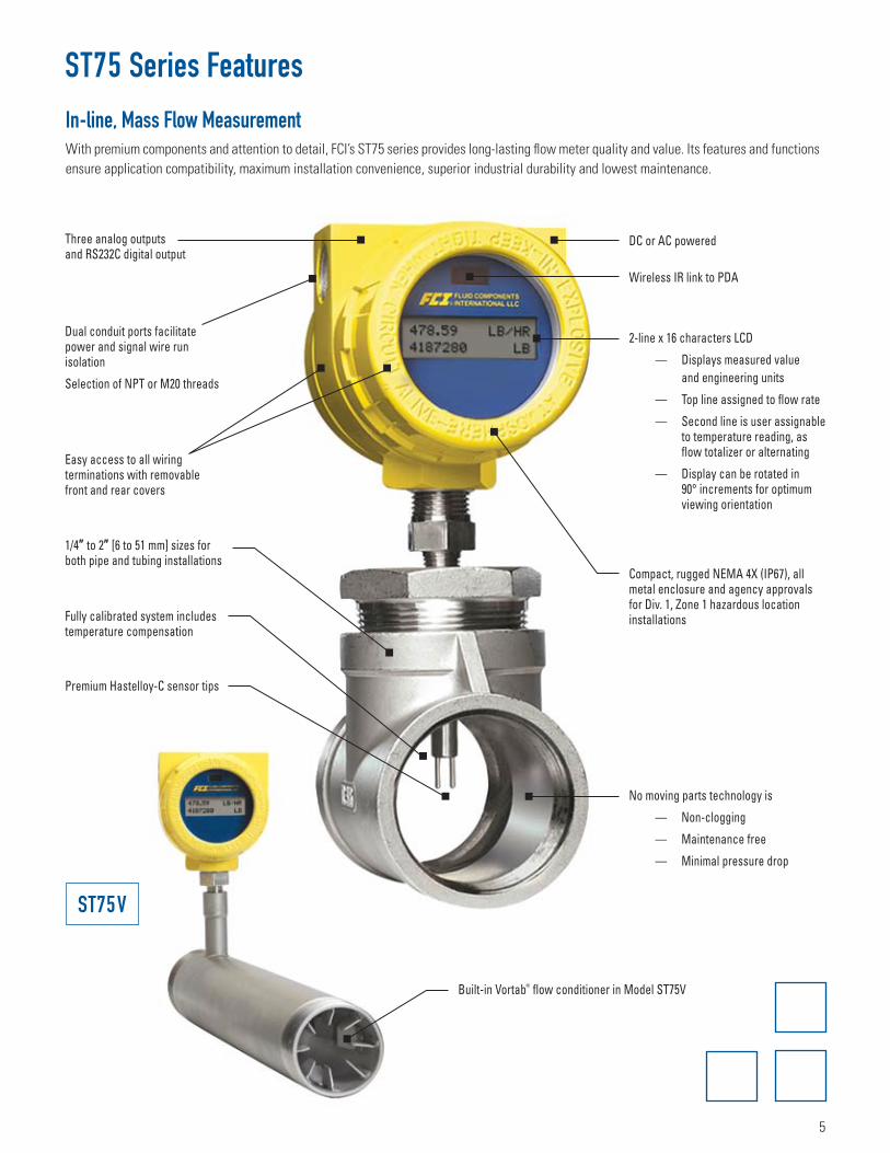
ST75 Series Features
Three analog outputs and RS232C digital output
Dual conduit ports facilitate power and signal wire run isolation
Selection of NPT or M20 threads
1/4″ to 2″ [6 to 51 mm] sizes for both pipe and tubing installations
Fully calibrated system includes temperature compensation
Premium Hastelloy-C sensor tips
Easy access to all wiring terminations with removable front and rear covers
2-line x 16 characters LCD
— Displays measured value and engineering units
— Top line assigned to flow rate
— Second line is user assignable to temperature reading, as flow totalizer or alternating
— Display can be rotated in 90° increments for optimum viewing orientation
Compact, rugged NEMA 4X (IP67), all metal enclosure and agency approvals for Div. 1, Zone 1 hazardous location installations
No moving parts technology is
— Non-clogging
— Maintenance free
— Minimal pressure drop
DC or AC powered
Wireless IR link to PDA
Built-in Vortab® flow conditioner in Model ST75V
In -line, Mass Flow MeasurementWith premium components and attention to detail, FCI’s ST75 series provides long-lasting flow meter quality and value. Its features and functions ensure application compatibility, maximum installation convenience, superior industrial durability and lowest maintenance.
ST75V
5
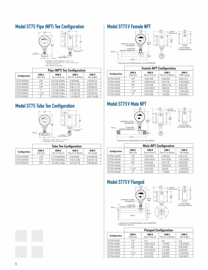
Model ST75V Male NPT
Configuration DIM A Pipe Size
DIM B Top to Flow CL
DIM C Flow CL to Bottom
DIM D Tee Length
ST75V-XXXCN 1/4″ 5.50 [140] 0.38 [9,5] 5.00 [127]ST75V-XXXEN 1/2″ 5.69 [144,5] 0.42 [10,6] 7.50 [190,5]ST75V-XXXFN 3/4″ 6.45 [164] 0.51 [13] 9.00 [229]ST75V-XXXGN 1″ 6.44 [163,5] 0.65 [16,5] 9.00 [229]ST75V-XXXHN 1 1/2″ 6.42 [163] .95 [24] 13.50 [343]ST75V-XXXJN 2″ 6.43 [163] 1.19 [30] 18.00 [457]
Male NPT Configuration
Model ST75 Pipe (NPT) Tee Configuration
Configuration DIM A Pipe Size
DIM B Top to Flow CL
DIM C Flow CL to Bottom
DIM D Tee Length
ST75-XXXAXX 1/4″ 6.0 [152,4] Max. 0.38 [9,65] 1.54 [39,12]ST75-XXXBXX 1/2″ 6.5 [165,1] Max. 0.56 [14,22] 2.28 [57,91]ST75-XXXCXX 3/4″ 7.0 [177,8] Max. 0.68 [17,27] 2.56 [65,02]ST75-XXXDXX 1″ 7.3 [185,4] Max. 0.86 [21,84] 2.92 [74,17]ST75-XXXEXX 1 1/2″ 7.8 [198,1] Max. 1.17 [29,72] 3.82 [97,03]ST75-XXXFXX 2″ 8.0 [203,2] Max. 1.42 [36,07] 4.66 [118,40]
Pipe (NPT) Tee Configuration
Model ST75 Tube Tee Configuration
Configuration DIM A Pipe Size
DIM B Top to Flow CL
DIM C Flow CL to Bottom
DIM D Tee Length
ST75-XXXGXX 1/4″ 5.7 [144,8] Max. 0.33 [8,39] 2.34 [59,44]ST75-XXXHXX 1/2″ 5.9 [149,9] Max. 0.53 [13,46] 2.84 [72,14]ST75-XXXJXX 3/4″ 7.8 [198,1] Max. 0.87 [22,10] 3.86 [98,04]
Tube Tee Configuration
Configuration DIM A Pipe Size
DIM B Top to Flow CL
DIM C Flow CL to Bottom
DIM D VMR Length
ST75V-XXXCE 1/4″ 5.50 [140] 0.38 [9,5] 5.00 [127]ST75V-XXXEE 1/2″ 5.69 [144,5] 0.57 [14] 7.50 [190,5]ST75V-XXXFE 3/4″ 6.45 [164] 0.69 [17,5] 9.00 [229]ST75V-XXXGE 1″ 6.44 [163,5] 0.88 [22] 9.00 [229]ST75V-XXXHE 1 1/2″ 6.42 [163] 1.25 [32] 13.50 [343]ST75V-XXXJE 2″ 6.43 [163] 1.50 [38] 18.00 [457]
Female NPT Configuration
Model ST75V Female NPT
Model ST75V Flanged
Configuration DIM A Pipe Size
DIM B Top to Flow CL
DIM C Flow CL to Bottom
DIM D Tee Length
ST75V-XXXCF 1/4" n/a n/a n/aST75V-XXXEF 1/2" 5.69 [144,5] 1.75 [45] 7.50 [190,5]ST75V-XXXFF 3/4" 6.45 [164] 1.94 [49] 9.00 [229]ST75V-XXXGF 1" 6.44 [163,5] 2.12 [54] 9.00 [229]ST75V-XXXHF 1 1/2" 6.42 [163] 2.50 [64] 13.50 [343]ST75V-XXXJF 2" 6.43 [163] 3.00 [76] 18.00 [457]
Flanged Configuration
6
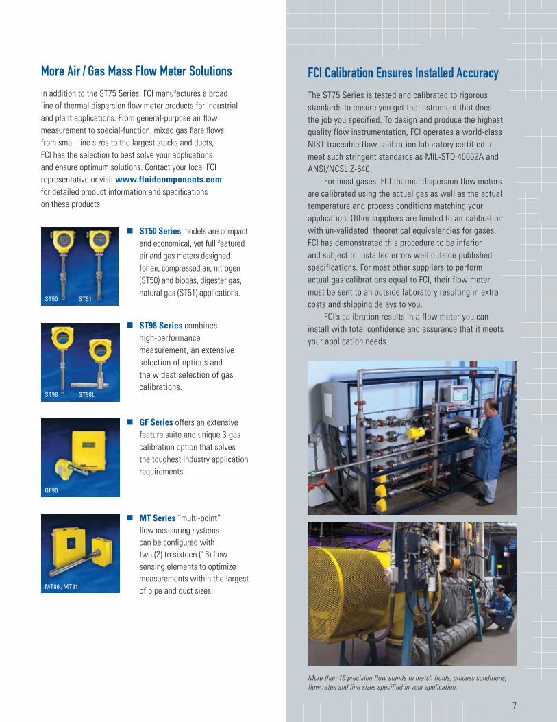
More Air / Gas Mass Flow Meter SolutionsIn addition to the ST75 Series, FCI manufactures a broad line of thermal dispersion flow meter products for industrial and plant applications. From general-purpose air flow measurement to special-function, mixed gas flare flows; from small line sizes to the largest stacks and ducts, FCI has the selection to best solve your applications and ensure optimum solutions. Contact your local FCI representative or visit www.fluidcomponents.com for detailed product information and specifications on these products.
g ST50 Series models are compact and economical, yet full featured air and gas meters designed for air, compressed air, nitrogen (ST50) and biogas, digester gas, natural gas (ST51) applications.
g ST98 Series combines high-performance measurement, an extensive selection of options and the widest selection of gas calibrations.
g GF Series offers an extensive feature suite and unique 3-gas calibration option that solves the toughest industry application requirements.
g MT Series “multi-point” flow measuring systems can be configured with two (2) to sixteen (16) flow sensing elements to optimize measurements within the largest of pipe and duct sizes.
7
FCI Calibration Ensures Installed AccuracyThe ST75 Series is tested and calibrated to rigorous standards to ensure you get the instrument that does the job you specified. To design and produce the highest quality flow instrumentation, FCI operates a world-class NIST traceable flow calibration laboratory certified to meet such stringent standards as MIL-STD 45662A and ANSI/NCSL Z-540.
For most gases, FCI thermal dispersion flow meters are calibrated using the actual gas as well as the actual temperature and process conditions matching your application. Other suppliers are limited to air calibration with un-validated theoretical equivalencies for gases. FCI has demonstrated this procedure to be inferior and subject to installed errors well outside published specifications. For most other suppliers to perform actual gas calibrations equal to FCI, their flow meter must be sent to an outside laboratory resulting in extra costs and shipping delays to you.
FCI’s calibration results in a flow meter you can install with total confidence and assurance that it meets your application needs.
More than 16 precision flow stands to match fluids, process conditions, flow rates and line sizes specified in your application.
GF90
ST98 ST98L
ST50 ST51
MT86 / MT91
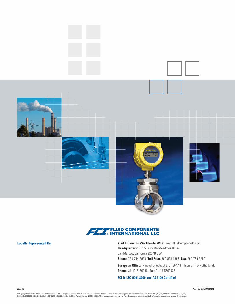
Visit FCI on the Worldwide Web: www.fluidcomponents.comHeadquarters: 1755 La Costa Meadows DriveSan Marcos, California 92078 USAPhone: 760-744-6950 Toll Free: 800-854-1993 Fax: 760-736-6250
European Office: Persephonestraat 3-01 5047 TT Tilburg, The NetherlandsPhone: 31-13-5159989 Fax: 31-13-5799036
FCI is ISO 9001:2000 and AS9100 Certified
Locally Represented By:
© Copyright 2009 by Fluid Components International LLC. All rights reserved. Manufactured in accordance with one or more of the following patents: US Patent Numbers: 4,929,088, 4,967,593, 4,981,368, 4,994,780, 5,111,692, 5,600,528, 5,780,737, 5,913,250, 6,208,254, 6,340,243, 6,628,202, 6,843,110, China Patent Number: ZL00815586.0. FCI is a registered trademark of Fluid Components International LLC. Information subject to change without notice.
Doc. No. 02MK011523H0809 0K
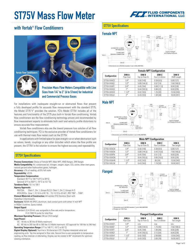
ST75V Mass Flow Meter with Vortab® Flow Conditioners
Precision Mass Flow Meters Compatible with LineSizes from 1/4” to 2” [6 to 51mm] for Industrialand Commercial Process Gases
Vortab Flow Conditioners
ST75V Specifications
ST75V Specifications
Process Connections: Choice of Female NPT, Male NPT, ANSI flanges, DIN flangesMedia Compatibility: Air, compressed air, nitrogen, oxygen, argon, CO2, ozone, other inert gases, natural gas and other hydrocarbon gases, hydrogen.Accuracy: ±1% of reading, ±0.5% full scaleRepeatability: ±0.5%Temperature Compensation:
Standard: 40 °F to 100 °F [4 °C to 38 °C]Optional: 0 °F to 250 °F [ -18 °C to 121 °C]
Turndown Ratio: 10:1 to 100:1Agency Approvals:
FM/CSA: Class 1, Div. 1, Groups B,C,D; Class 1, Div. 2, Groups A-D ATEX/IECEx: Zone 1, II 2 G Ex d IIC T6…T3; II 2 D Ex tD A21, IP67 T90°…T300°
Element Materials of Construction: All-welded 316 Stainless Steel withHastelloy-C thermowells.Enclosure: NEMA 4X [IP67], aluminum, dual conduit ports with either ½ inch NPT or M20x1.5 entries. Epoxy coated.Output Signal:
Standard: (2) 4-20 mA, user assignable to flow rate and/or temperature (1) 0-1000 Hz pulse for total flow
Maximum Operating Pressure: 240 psi [16.5 bar(g)]Input Power:
DC: 18 Vdc to 36 Vdc (6 Watts maximum)AC: 85 Vdc to 265 Vac 85 to 265 Vac (12 Watts maximum) (CE approval for 100 Vac to 240 Vac)
Operating Temperature Range: 0 °F to 140 °F [ -18 °C to 60 °C]Digital Display (Optional): Two-line x 16 characters LCD. Displays measured value and engineering units. Top line assigned to flow rate. Second line is user assignable to temperature reading, as flow totalizer or alternating. Display can be rotated in 90° increments for optimum viewing orientation.
For installations with inadequate straight-run or obstructed flows that prevent a fully developed profile for accurate flow measurement with the standard ST75, the Model ST75”V” provides the solution. FCI’s Model ST75V includes all of the features and functionality of the ST75 plus built-in Vortab flow conditioning. Vortab flow conditioners are the flow conditioning technology proven and recommended by flow measurement experts to eliminate both swirl and velocity profile distortions to ensure accurate flow measurement.
Vortab flow conditioners also are the lowest pressure loss solution of all flow conditioning techniques. FCI is the exclusive provider of Vortab flow conditioners for use with thermal mass flow meters such as the ST75V.
In applications with limited space for pipe straight-run or when obstructors such as valves, bends, couplings or any other disturber which alters the flow profile are present, the ST75V is the solution to ensure the highest accuracy and repeatability.
Female NPT
Male NPT
Flanged
Configuration DIM A Pipe Size
DIM B Top to Flow CL
DIM C Flow CL to Bottom
DIM D VMR Length
ST75V-XXXCE 1/4″ 5.50 [140] 0.38 [9,5] 5.00 [127]ST75V-XXXEE 1/2″ 5.69 [144,5] 0.57 [14] 7.50 [190,5]ST75V-XXXFE 3/4″ 6.45 [164] 0.69 [17,5] 9.00 [229]ST75V-XXXGE 1″ 6.44 [163,5] 0.88 [22] 9.00 [229]ST75V-XXXHE 1 1/2″ 6.42 [163] 1.25 [32] 13.50 [343]ST75V-XXXJE 2″ 6.43 [163] 1.50 [38] 18.00 [457]
Female NPT Configuration
Configuration DIM A Pipe Size
DIM B Top to Flow CL
DIM C Flow CL to Bottom
DIM D Tee Length
ST75V-XXXCN 1/4″ 5.50 [140] 0.38 [9,5] 5.00 [127]ST75V-XXXEN 1/2″ 5.69 [144,5] 0.42 [10,6] 7.50 [190,5]ST75V-XXXFN 3/4″ 6.45 [164] 0.51 [13] 9.00 [229]ST75V-XXXGN 1″ 6.44 [163,5] 0.65 [16,5] 9.00 [229]ST75V-XXXHN 1 1/2″ 6.42 [163] .95 [24] 13.50 [343]ST75V-XXXJN 2″ 6.43 [163] 1.19 [30] 18.00 [457]
Male NPT Configuration
Configuration DIM A Pipe Size
DIM B Top to Flow CL
DIM C Flow CL to Bottom
DIM D Tee Length
ST75V-XXXCF 1/4″ n/a n/a n/aST75V-XXXEF 1/2″ 5.69 [144,5] 1.75 [45] 7.50 [190,5]ST75V-XXXFF 3/4″ 6.45 [164] 1.94 [49] 9.00 [229]ST75V-XXXGF 1″ 6.44 [163,5] 2.12 [54] 9.00 [229]ST75V-XXXHF 1 1/2″ 6.42 [163] 2.50 [64] 13.50 [343]ST75V-XXXJF 2″ 6.43 [163] 3.00 [76] 18.00 [457]
Flanged Configuration
Page 1 of 2
ORDERING GUIDE: ST75V Mass Flow Meter with Vortab® Flow Conditioners
Visit FCI on the Worldwide Web: www.fluidcomponents.comHeadquarters: 1755 La Costa Meadows DriveSan Marcos, California 92078 USAPhone: 760-744-6950 Toll Free: 800-854-1993 Fax: 760-736-6250 European Office: Persephonestraat 3-01 5047 TT Tilburg, The NetherlandsPhone: 31-13-5159989 Fax: 31-13-5799036
FCI is ISO 9001:2000 and AS9100 Certified
Locally Represented By:
© Copyright 2009 by Fluid Components International LLC. All rights reserved. Manufactured in accordance with one or more of the following patents: US Patent Numbers: 4,929,088, 4,967,593, 4,981,368, 4,994,780, 5,111,692, 5,600,528, 5,780,737, 5,913,250, 6,208,254, 6,340,243, 6,628,202, 6,843,110, China Patent Number: ZL00815586.0. FCI is a registered trademark of Fluid Components International LLC. Information subject to change without notice.
Doc. No. 02MK011529D0409 0K
Base Unit, Enclosure Style (Block 1) Enclosures: All Aluminum, NEMA 4X/IP67 rated, epoxy coated Code
Blind, Integral Transmitter, with two 1/2″ FNPT cable entries 1
Integral Transmitter with Local Digital Display, with two 1/2″ FNPT cable entries 2
Remote Transmitter w/ two 1/2″ FNPT cable entries and w/Digital Display.(Specify cable length in Block 10) 4
Blind, Integral Transmitter, w/ two M20x1.5 cable entries A
Integral Transmitter with Local Digital Display, w/ two M20x1.5 cable entries B
Remote Transmitter w/ two M20x1.5 cable entries and w/Digital Display.(Specify cable length in Block 10) C
Gas Medium and System Calibration 2 (Block 8) Code
Air B
Air Equivalence (Oxygen, Chlorine, Ammonia, etc.) C
Nitrogen, Helium, Argon, CO2, Compressed Air E
Hydrocarbons (e.g. Natural Gas, Ethane, Methane, Propane, Ethylene, Propylene, Mixed) F
Hydrogen or hydrogen mixture G
Air, Compressed Air H
Air Equivalence (e.g. Oxygen, Chlorine, Ammonia, etc.) J
Nitrogen, Argon K
CO2, Ethylene, Ethane L
Propane, Propylene M
Butane, Pentane N
Methane, Helium, Natural Gas P
Hydrogen R
Calibration 3 and Calibration Temperature Conditions (Block 9) Code
High Accuracy 1% Calibration and Standard Conditions +40 °F to 100 °F [+4 °C to 38 °C] w/Vortab Q
High Accuracy 1% Calibration and Extended Temperature Compensation 0 °F to 250 °F [-18 °C to 121 °C] w/Vortab T
Other, Agency approved,customer specified W
Interconnecting Cable Length for Remote Configurations 4 (Block 10) Code
Not required (Specify with integral configuations) 0
10′ [3 meters] A
25′ [7,6 meters] B
50′ [15 meters] C
Custom length (Cannot exceed 50 ′ [15 meters]) W
Part Number Description
019819-01 Software Interface Package for PDA/PalmOS
020802-01 PDA, Palm® model TungstenTM E2
FC88 Portable Hand-held Communicator
014108-02 PC Interface Communications Kit, For RS232 serial port connection
DM10-N Digital Display/Readout, LCD, 4-20 mA loop pow
DM10-FC DM10 with FM and CSA approvals
DM10-KIT1 Panel Mount Kit for DM10
DM10-KIT2 2 inch (52 mm) Pipe Mount Kit for DM10 (Stainless steel)
DM15 Digital Display/Readout, LED 115/230 Vac powered
DM15-ALM Same as DM-15 with user programmable alarm limit, relay output
DM20 Digital Display Readout, 8-digit LCD Pulse totalizer/counter
Optional Accessories
Power Supply (Block 3) Code
DC; 18 - 36 V 1
AC; 85 - 265 V, 50/60 Hz 2
Line Size (Block 4) Code
1/4″ (Available only with NPT, Block 5 must be Code E or N) 5 C
1/2″ E
3/4″ F
1″ G
1-1/2″ H
2″ J
Process Connection Type (Block 5) Code
Female NPT E
Male NPT N
Flanged, #150 CLASS F
Other; agency approved, customer specified(If selected, Block 6 and 7 which follow must also be Code WW only) W
Process Connection Size, Material, Rating, Finish Details (Block 6 & 7) Code
1/4″ NPT (must be selected if Block 4 is Code C) Q0
1/2″ NPT H0
3/4″ NPT T0
1″ NPT 10
1-1/2″ NPT B0
2″ NPT 20
1/2″ ANSI flanged 150 lb RF ANSI 16.5, 316L Stainless steel HG
3/4″ ANSI flanged 150 lb RF ANSI 16.5, 316L Stainless steel TG
1″ ANSI flanged 150 lb RF ANSI 16.5, 316L Stainless steel 1G
1-1/2″ ANSI flanged 150 lb RF ANSI 16.5, 316L Stainless steel BG
2″ ANSI flanged 150 lb RF ANSI 16.5, 316L Stainless steel 2G
DN15 DIN flanged PN40, Form C per DIN2526 or Form B1 per DIN EN1092-1 in 316L ss D2
DN25 DIN flanged PN40, Form C per DIN2526 or Form B1 per DIN EN1092-1 in 316L ss E2
DN40 DIN flanged PN40, Form C per DIN2526 or Form B1 per DIN EN1092-1 in 316L ss G2
DN50 DIN flanged PN16, Form C per DIN2526 or Form B1 per DIN EN1092-1 in 316L ss J2
Other; agency approved, customer specified WW
Model ST75V-Block No. 1 2 3 4 5 6 7 8 9 10
Notes
2 . Must use FCI’s AVAL program to determine letter code. AVAL is a custom flow meter optimizer program which considers gas medium, flow range, pipe size and other conditions to determine best calibration and supplies FCI letter code to be used here. AVAL is available on-line at www.fluidcomponents.com or consult local FCI representative/distributor.
3. Calibration accuracy is ±% of reading, ±0.5% of full scale.
4. Fixed cable length with instrument calibrated together as a matched set. Cable may be coiled, but not cut.
5. Certified Material Test Report (CMTR) not available with ST75V 1/4″.
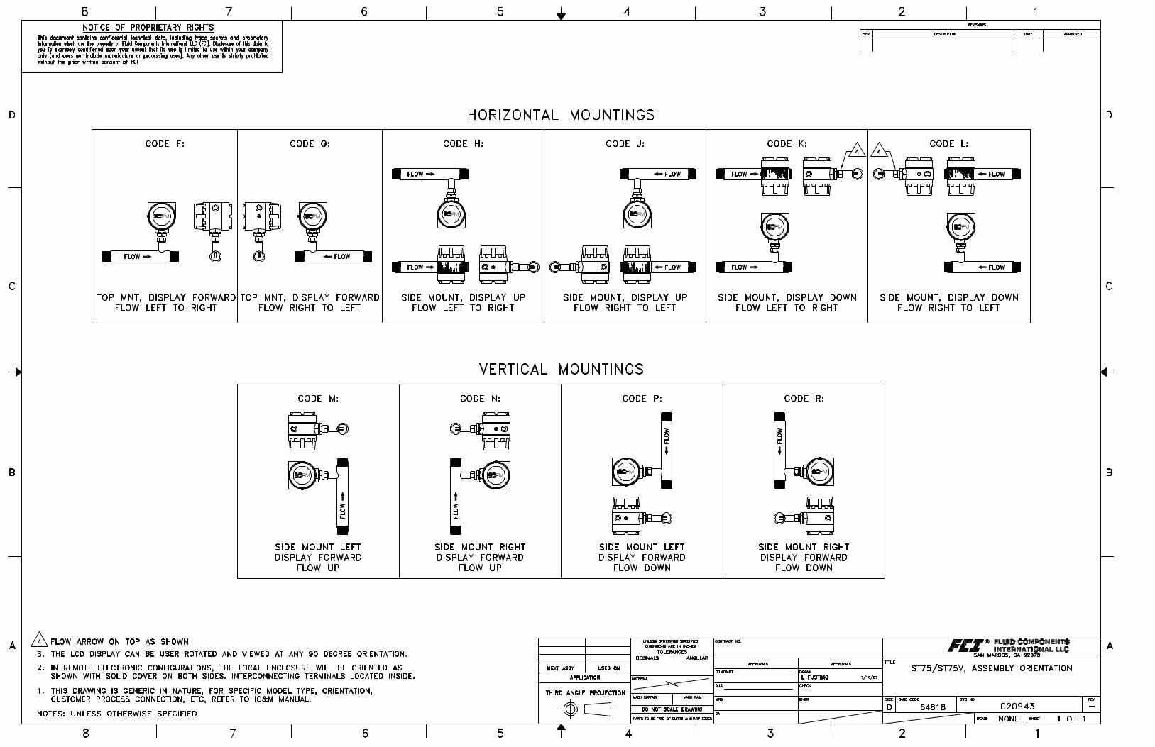
Pipe Installation, Display/Transmitter Mounting Orientation and Flow Direction (Block 2)
Horizontal Pipe Code Vertical Pipe CodeTop mnt, display face frwd, flow L-R F Side mnt L, display face frwd, flow up MTop mnt, display face frwd, flow R-L G Side mnt R, display face frwd, flow up NSide mnt, display face up, flow L-R H Side mnt L, display face frwd, flow down PSide mnt, display face up, flow R-L J Side mnt R, display face frwd, flow down RSide mnt, display face down, flow L-R K For visual representation, refer to FCI drawing
number 020943Side mnt, display face down, flow R-L L