fcc rpt mtx900 1of3 revo 060915 sr4244 · this reporting format is consistent with the test report...
TRANSCRIPT

FCC ID: AZ489FT4826 SR4244
N&E EME Form-SAR-Rpt-Rev. 5.02 Page 1 of 29
Certificate Number: 2518.01
FCC ID: AZ489FT4826 DECLARATION OF COMPLIANCE SAR ASSESSMENT Part 1 of 3
Networks & Enterprise EME Test Laboratory
8000 West Sunrise Blvd Fort Lauderdale, FL. 33322
Date of Report: September 15, 2006 Report Revision: O Report ID: FCC rpt_MTX900_Rev_O_0609015_SR4244
Responsible Engineer: Stephen C. Whalen (SR Staff EME Eng.) Date/s Tested: 7/28/2006-8/8/2006 Manufacturer/Location: Motorola – Penang Sector/Group/Div.: N&E/GTDG Date submitted for test: 7/27/2006 DUT Description: UHF 1 403-470 MHz 4W; Trunking Popular w/o Keypad & Display Test TX mode(s): CW Max. Power output: 5.3W Nominal Power: 4W Tx Frequency Bands: 403-470 MHz. Signaling type: FM Model(s) Tested: PMUE1678B Model(s) Certified: PMUE1678B Serial Number(s): 004TGL1003 Classification: Occupational/Controlled Rule Part(s): 90 Approved Accessories: Antenna(s): PMAE4002A (Stubby 403-433 MHz ¼ wave, -4.5 dBi); PMAE4003A (Stubby 430-470 MHz ¼ wave, -4.5dBi); NAE6483AR (Whip 403-520 MHz ¼ wave, -2 dBi). Battery(ies): HNN9008C (NiMH High Capacity Battery); HNN9009A (NiMH Ultra High Capacity Battery); HNN9010B (NiMH Ultra High Capacity Battery Factory Mutual); HNN9011B (NiCd High Capacity Battery Factory Mutual); HNN9012B (NiCd High Capacity Battery); HNN9013D (Li Ion High Capacity Battery). Body worn accessory(ies): HLN9670A (Leather Case, Thin Battery w/Swivel); HLN9676A (Leather Case, Std. Battery w/Swivel); HLN9714A (Belt Clip); HLN9952A (Belt Clip Carry Holder); HLN9677A (Leather DTMF Case, Thin Battery w/Belt Loop); HLN9689A (Leather DTMF Case, Std. battery w/Belt Loop); HLN9690A (Leather DTMF Case, Thin Battery w/Swivel); HLN9694A (Leather DTMF Case, Std. Battery w/Swivel); HLN9701B (Hard Nylon Case, Belt loop, D-ring, (for all battery sizes)); HLN9652A (Leather Case, Thin Battery w/Belt Loop); HLN9665A (Leather Case, Std. Battery w/Belt Loop). Audio/Data cable accessory(ies): See section 3.0 for list of approved audio acc.
Max. Calc. : 1-g Avg. SAR: 5.54 W/kg (Body); 10-g Avg. SAR: 4.00 W/kg (Body) Max. Calc. : 1-g Avg. SAR: 4.06 W/kg (Face); 10-g Avg. SAR: 3.05 W/kg (Face) Based on the information and the testing results provided herein, the undersigned certifies that when used as stated in the operating instructions supplied, said product complies with the national and international reference standards and guidelines listed in section 2.0 of this report. This report shall not be reproduced without written approval from an officially designated representative of the Motorola EME Laboratory. This reporting format is consistent with the test report guidelines of the TIA TSB-150 December 2004 The results and statements contained in this report pertain only to the device(s) evaluated.
Signature on file
Ken Enger N&E EME Lab Senior Resource Manager, Laboratory Director,
Approval Date: 9/15/2006
Certification Date: [ ] Certification No.: [ ]

FCC ID: AZ489FT4826 SR4244
N&E EME Form-SAR-Rpt-Rev. 5.02 Page 2 of 29
Part 1 of 2 1.0 Introduction and Overview...................................................................................... 3 2.0 Referenced Standards and Guidelines ..................................................................... 3 2.1 SAR Limits ................................................................................................... 4 3.0 Description of Device Under Test (DUT) ............................................................... 4 4.0 Description of Test System ..................................................................................... 5 4.1 Description of Robotics/Probes/Readout Electronics................................... 5 4.2 Description of Phantom(s)............................................................................ 6 4.2.1 Flat Phantom................................................................................... 6 4.2.2 SAM Phantom ................................................................................ 6 4.3 Description of Equivalent Tissues ................................................................ 6 5.0 Additional Test Equipment...................................................................................... 7 6.0 SAR Measurement System Verification.................................................................. 7 6.1 Equivalent Tissue Test results ...................................................................... 7 6.2 System Check Test results ............................................................................ 8 7.0 DUT Test Strategy and Methodology ..................................................................... 8 7.1 DUT Configuration(s) .................................................................................. 8 7.2 Device Positioning Procedures ..................................................................... 9 7.2.1 Body ............................................................................................... 9 7.2.2 Head ............................................................................................. 10 7.2.3 Face .............................................................................................. 10 8.0 Environmental Test Conditions............................................................................. 10 9.0 Test Results Summary........................................................................................... 10 9.1 Highest SAR results calculation methodology ........................................... 14 10.0 Conclusion............................................................................................................. 14 APPENDICES A Measurement Uncertainty ..................................................................................... 15 B Probe Calibration Certificates ............................................................................... 18 Part 2 of 3 C Dipole Calibration Certificates................................................................................ 2 D Test System Verification Scans............................................................................... 9 Part 3 of 3 E DUT Scans (Shortened Scans and Highest SAR configurations) ........................... 2 F DUT Supplementary Data (e.g. Power Slump) ....................................................... 7 G DUT Test Position Photos....................................................................................... 9 H DUT and Body-worn Accessory Photos ............................................................... 11 I DUT Antenna Separation Distances and Offered Accessory Test Status ............ 13
Report REVISION HISTORY
Date Revision Comments
9/15/06 O Design change to the harmonic filters circuitry to improve tx. conducted spurious
rejection. Additional by-passes & ferrite beads to improve the tx. radiated
emissions when accessories were attached.

FCC ID: AZ489FT4826 SR4244
N&E EME Form-SAR-Rpt-Rev. 5.02 Page 3 of 29
1.0 Introduction and Overview
This report details the utilization, test setup, test equipment, and test results of the Specific Absorption Rate (SAR) measurements performed at the N&E EME Test Lab for the model number PMUE1678B of FCC ID: AZ489FT4826. The results herein clearly demonstrate compliance with FCC Occupational/Controlled RF Exposure limits of 8.0 mW/g per the requirements of 47 CFR 2.1093(d).
2.0 Referenced Standards and Guidelines
This product is designed to comply with the following national and international standards and guidelines. • United States Federal Communications Commission, Code of Federal Regulations; Rule Part
47CFR § 2.1093 sub-part J:1999 • Federal Communications Commission, “Evaluating Compliance with FCC Guidelines for
Human Exposure to Radio frequency Electromagnetic Fields”, OET Bulletin 65, Supplement C (Edition 01-01), FCC, Washington, D.C.: June 2001.
• IEEE 1528, 2003 "Recommended Practice for Determining the Peak Spatial-Average Specific Absorption Rate (SAR) in the Human Head from Wireless Communications Devices: Measurement Techniques"
• American National Standards Institute (ANSI) / Institute of Electrical and Electronic Engi-neers (IEEE) C95. 1-1992
• Institute of Electrical and Electronic Engineers (IEEE) C95.1-1999 Edition • International Commission on Non-Ionizing Radiation Protection (ICNIRP) 1998 • Ministry of Health (Canada) Safety Code 6. Limits of Human Exposure to Radio frequency
Electromagnetic Fields in the Frequency Range from 3 kHz to 300 GHz, 1999 • Australian Communications Authority Radiocommunications (Electromagnetic Radiation -
Human Exposure) Standard 2003 • ANATEL, Brazil Regulatory Authority, Resolution No. 303 of July 2, 2002 "Regulation of the
limitation of exposure to electrical, magnetic, and electromagnetic fields in the radio frequency range between 9KHz and 300 GHz." and “Attachment to resolution # 303 from July 2, 2002”

FCC ID: AZ489FT4826 SR4244
N&E EME Form-SAR-Rpt-Rev. 5.02 Page 4 of 29
2.1 SAR Limits
SAR (W/kg) EXPOSURE LIMITS (General Population /
Uncontrolled Exposure Environment)
(Occupational / Controlled Exposure
Environment) Spatial Average - ANSI - (averaged over the whole body)
0.08
0.4
Spatial Peak - ANSI - (averaged over any 1-g of tissue)
1.60
8.0
Spatial Peak – ICNIRP/ANSI - (hands/wrists/feet/ankles averaged over 10-g)
4.0
20.0
Localized SAR - ICNIRP - (Head and Trunk 10-g) 2.0 10.0
3.0 Description of Device Under Test (DUT)
FCC ID: AZ489FT4826 is a UHF portable two-way radio that operates using frequency modulation (FM) incorporating traditional simplex transmission protocol. This radio is intended to be assessed using CW transmission via its’ inherent test mode signaling capability. The model represented under this filing utilizes removable antennas and is capable of transmitting in the 403-470 MHz band. The nominal output power is 4W with maximum output power of 5.3W as defined by the upper limit of the production line final test station. The intended operating positions are “at the face” with the DUT 1 to 2 inches from the mouth, and “at the body” by means of the offered body-worn accessories. Body-worn audio and PTT operation is accomplished by means of optional remote accessories that connect to the radio. This device will be marketed to and used by employees solely for occupational operations, such as public safety agencies, e.g. police, fire and emergency medical. User training is the responsibility of these agencies, which can be expected to employ the usage instructions, safety information and operational cautions set forth in the user's manual, instructional sessions or other means. Motorola also makes available to its customers training classes on the proper use of two-way radios and wireless data devices. FCC ID: AZ489FT4826 is offered with the options and accessories listed on the coversheet of this report as well as the audio accessories listed below:
Audio Acc.: AAHMN9052E Standard Remote Speaker Microphone AAHMN9053E Noise-Cancelling Remote Speaker Microphone NTN1722A Integrated Ear Microphone/Receiver System w/PTT NTN1723A Integrated Ear Microphone/Receiver System w/Palm PTT NTN1724A Integrated Ear Microphone/Receiver System w/Ring PTT AARMN4019A Over-the-Head, Medium weight, Dual Muff Headset w/Noise Cancelling Microphone & In-line PTT AARMN4018B Light Weight Headset w/Boom Microphone & In-line PTT AARMN4031B Light Weight Headset w/Swivel Boom Microphone AARMN4017A Ultra Light Headset AARMN4032A Over-the-Head, Medium Weight, Dual Muff Headset w/Noise Cancelling Microphone AARMN4022A Two Wire Earpiece w/ Microphone & PTT (Beige) AARMN4029A Two Wire Earpiece w/Microphone & PTT (Black) AARMN4021A One Wire Earpiece (Beige)

FCC ID: AZ489FT4826 SR4244
N&E EME Form-SAR-Rpt-Rev. 5.02 Page 5 of 29
AARMN4028A One Wire Earpiece (Black) RLN4941A Receive-Only Earpiece w/Translucent Tube, Rubber Eartip & 3.5mm
Plug RLN4922A Complete Discrete Earpiece Kit-use with any standard two wire earpiece
kit Other cable options: AAHLN9716C Audio Accessory Adaptor (Use w/GP300 Audio Accessories)
Test Output Power
A table of the characteristic power slump versus time is provided in Appendix F. 4.0 Description of Test System
4.1 Descriptions of Robotics/probes/Readout Electronics
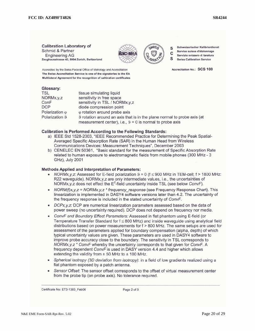
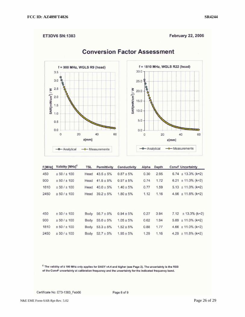
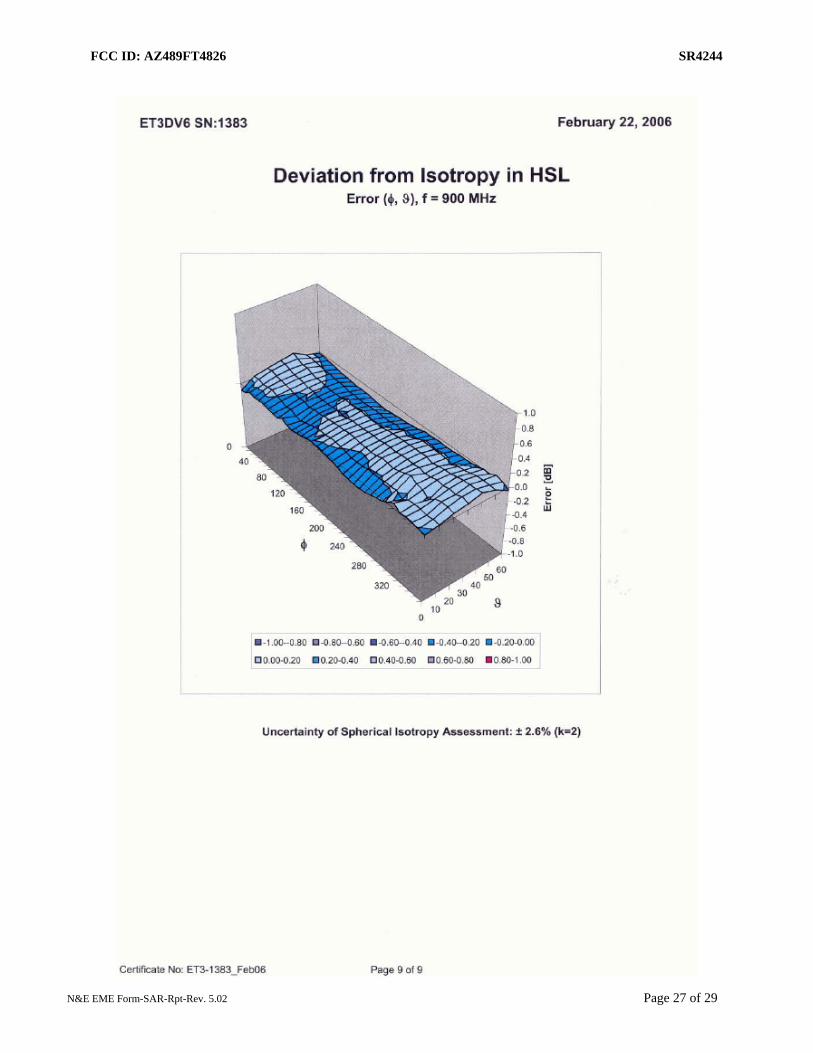
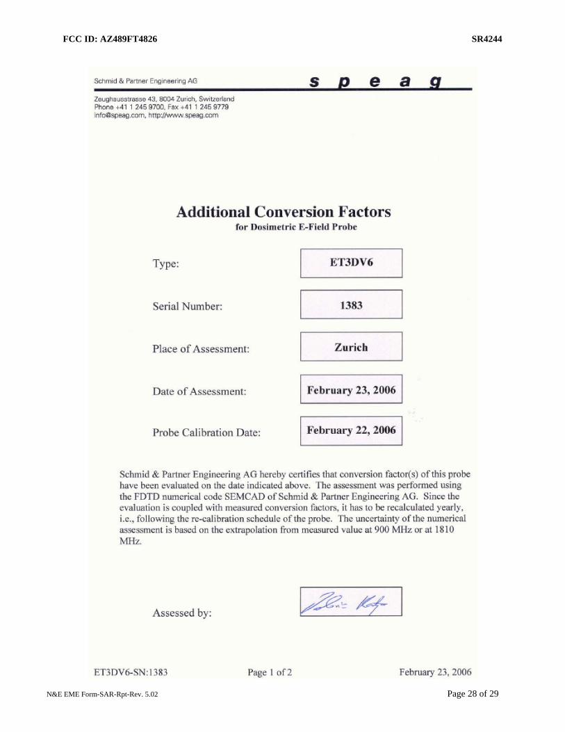
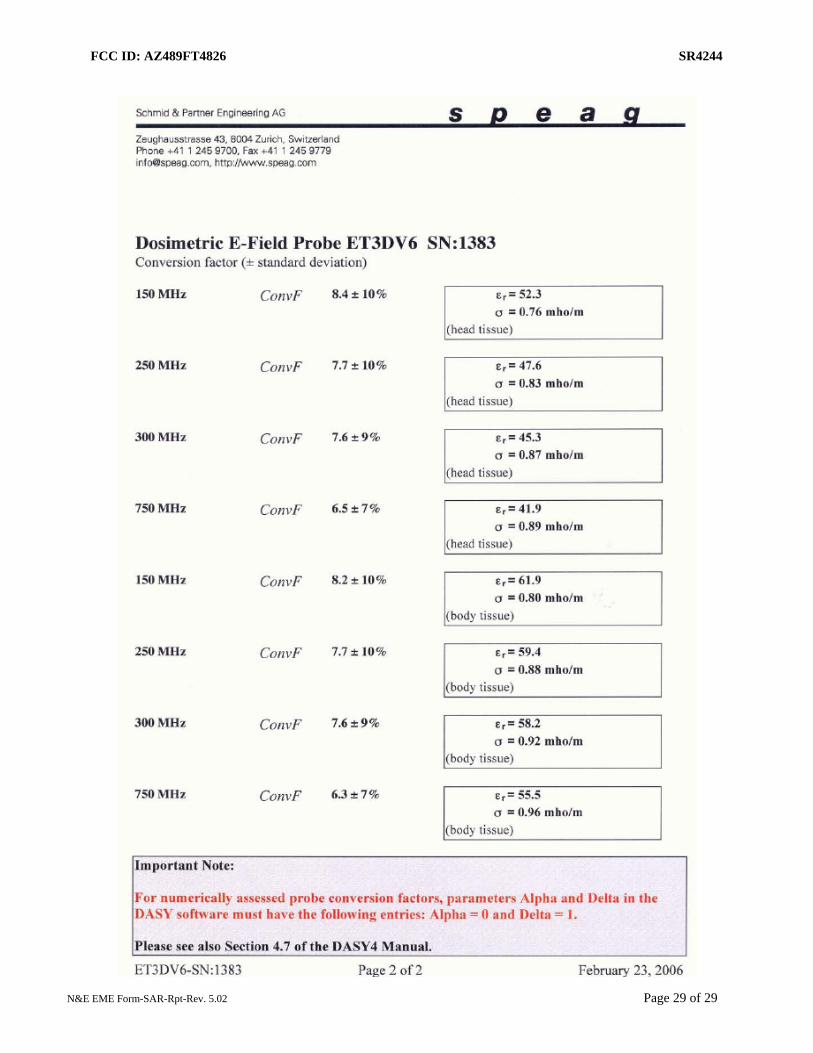
The laboratory utilizes a Dosimetric Assessment System (DASY4™) SAR measurement system Version 4.7 build 44 manufactured by Schmid & Partner Engineering AG (SPEAG™), of Zurich Switzerland. The test system consists of a Stäubli RX90L robot, DAE3, and ET3DV6 E-Field probes. Please reference the SPEAG user manual and application notes for detailed probe, robot, and SAR computational procedures. Section 5.0 presents relevant test equipment information. Appendices B and C present the applicable calibration certificates. The E-field probe first scans a coarse grid over a large area inside the phantom in order to locate the interpolated maximum SAR distribution. After the coarse scan measurement, the probe is automatically moved to a position at the interpolated maximum. The subsequent scan can directly use this position as reference for the cube evaluations.
4.2 Description of Phantom(s)

FCC ID: AZ489FT4826 SR4244
N&E EME Form-SAR-Rpt-Rev. 5.02 Page 6 of 29
4.2.1 Flat Phantom
Phantom Type
Phantom Material
Phantom Dimensions
(cm)
Support structure opening dimensions
(cm) Support structure
material
Loss Tangent (wood)
Flat
High Density Polyethylene
(HDPE) 80x30x20x0.2 68.58x20.32 Wood < 0.05
4.2.2 SAM Phantom NA
4.3 Description of Equivalent tissues
Type of Simulated Tissue
The simulated tissue used is compliant to that specified in FCC Supplement C (Edition 01-01) to OET Bulletin 65 (Edition 97-01) and IEEE 1528, 2003 "Recommended Practice for Determining the Peak Spatial-Average Specific Absorption Rate (SAR) in the Human Head from Wireless Communications Devices: Measurement Techniques". The sugar based simulate tissue is produced by placing the correct measured amount of De-ionized water into a large container. Each of the dried ingredients are weighed and added to the water carefully to avoid clumping. If the solution has a high sugar concentration the water is pre-heated to aid in dissolving the ingredients
Simulated Tissue Composition
450MHz % of listed ingredient
s Head Body Sugar 56.0 46.5 DGBE
(Glycol) NA NA Diacetin NA NA
De ionized -Water 39.1 50.53
Salt 3.8 1.87 HEC 1.0 1.0 Bact. 0.1 0.1
Reference section 6.1 for target parameters 5.0 Additional Test Equipment

FCC ID: AZ489FT4826 SR4244
N&E EME Form-SAR-Rpt-Rev. 5.02 Page 7 of 29
Equipment Type Model Number Serial Number Calibration Due Date Power Meter (Agilent) E4418B GB40206553 4/21/2007
Power Meter (HP) E4418B US39251150 4/20/2007 Power Sensor (HP) 8482H 1926A01906 12/12/2006 Power Sensor (HP) 8482B 3318A06773 4/19/2007
Power Meter (Agilent) E4418B GB 40206480 11/30/2006
Power Sensor (Agilent) 8482B 3318A07546 10/6/2006 Signal Generator (HP) 8656B 3334U14050 9/29/2006
AMP (Amplifier Research) 10WD1000 28782 CNR Bi-Directional Coupler (NARDA) 3020A 40295 7/18/2006
Network Analyzer (HP) 8753D 3410A09135 2/22/2007 Dielectric Probe Kit (HP) 85070C US99360076 CNR
Speag Dipole D450V2 1001 5/25/2008
6.0 SAR Measurement System Verification
The SAR measurements were conducted with probe model/serial number ET3DV6/SN1383. The system performance check was conducted daily and within 24 hours prior to testing. DASY output files of the probe/dipole calibration certificates and system performance test results are included in appendices B, C, D respectively. The table below summarizes the system performance check results normalized to 1W. Dipole validation scans at the head from SPEAG are provided in APPENDIX D. The N&E EME lab validated the dipole to the applicable IEEE system performance targets. Within the same day system validation was performed using FCC body tissue parameters to generate the system performance target values for body at the applicable frequency. The results of the N&E EME system performance validation are provided herein. 6.1 Equivalent Tissue Test Results
Simulated tissue prepared for SAR measurements is measured daily and within 24 hours prior to actual SAR testing to verify that the tissue is within 5% of target parameters at the center of the transmit band. This measurement is done using the applicable equipment indicated in section 5.0.
Actual versus Target tissue parameters (7/28/2006 – 8/8/2006)
FCC Body
Frequency (MHz)
Di-electric Constant
Target
Di-electric Constant
Meas. (Range)
Conductivity Target
S/m
Conductivity Meas. (Range)
S/m 436.5 56.8 55.8-56.7 0.94 0.90-0.93
450 56.7 55.5-56.4 0.94 0.91-0.94
IEEE Head

FCC ID: AZ489FT4826 SR4244
N&E EME Form-SAR-Rpt-Rev. 5.02 Page 8 of 29
Frequency (MHz)
Di-electric Constant
Target
Di-electric Constant
Meas. (Range)
Conductivity Target
S/m
Conductivity Meas. (Range)
S/m 436.5 43.7 44.2-44.6 0.87 0.85-0.87
450 43.5 43.9-44.2 0.87 0.87-0.88
6.2 System Check Test Results
Probe Serial #
Tissue Type
Probe Cal Date
Dipole Kit / Serial #
System Perf. Result when
normalized to 1W (mW/g)
Reference
S.A.R @ 1W (mW/g)
Test Date(s)
1383 FCC Body 2/22/06
SPEAG D450V2 /1001 4.31 +/-0.15 4.43 +/- 10%
7/28/06-7/31/06, 8/4/06, 8/7/06
6 test days
1383 IEEE Head 2/22/06
SPEAG D450V2 /1001 4.83 +/-0.03 5.11 +/- 10%
8/1/06-8/3/06, 8/8/06
4 test days Note: See APPENDIX D for an explanation of the reference SAR targets stated above.
(System performance results reflects the median performance +/- ½ of the test date(s) performance ranges)
The DASY4™ system is operated per the instructions in the DASY4™ Users Manual. The complete manual is available directly from SPEAG™. All measurement equipment used to assess EME SAR compliance was calibrated according to 17025 A2LA guidelines.
7.0 DUT Test Strategy and Methodology
7.1 DUT Configuration(s) PTT operation using Frequency Modulation (FM) in CW transmission mode. The DUT’s PTT switch is engaged and the radio is placed in the reported test positions presented in Appendix G. Test Plan
All options and accessories listed on the cover page of this report were considered in order to develop the SAR test plan for this product. SAR measurements were performed using a flat phantom with the applicable simulated tissue to assess performance at the body and face using the CW transmission modes. Note that a coarse-to-cube approximation methodology was utilized to determine the worst-case SAR performance configuration for each applicable body location. The test configurations that produced the highest SAR results for each body position using the coarse-to-cube approximation methodology were assessed using the full DASY4™ coarse and 7x7x7 cube scans.
Assessments at the Body [Pages 11, 12 of 29; Tables 1]

FCC ID: AZ489FT4826 SR4244
N&E EME Form-SAR-Rpt-Rev. 5.02 Page 9 of 29
- Assessment of the offered antennas of the 403-470MHz band using applicable test
configurations at the body. - Assessment of the offered batteries with the worst case configuration from the above. - Assessment of the offered body worn accessories with the worst case configuration
from the above. - Assessment of the offered audio accessories with the worst case configuration from the
above. - Assessment across the band of each offered antenna using the worst case configuration
from the above. Assessments at the Body 2.5cm [Page 12 of 29; Table 1] - Assessment with the DUT’s back and front separated 2.5cm from the phantom without
a body worn accessory using the worst case test configuration from the body assessment above.
Assessments at the Face [Page 13 of 29; Table 2] - Assessment of the offered antennas of the 403-470MHz band using applicable test
configurations at the face. - Assessment of the offered batteries with the worst case configuration from the above. - Assessment of the offered audio accessories with the worst case configuration from the
above. - Assessment across the band of each offered antenna using the worst case configuration
from the above. Shortened scan assessment at the Body and Face [Page 14 of 29; Table 3] - A “shortened” scan was performed using the test configuration that produced the
highest SAR results overall at the body and face. Note that the shortened scan is obtained by first running a coarse scan to find the peak area and then, using a newly charged battery, a cube scan only was performed. The shortened scan represents the cube scan performance results.
7.2 Device Positioning Procedures
Reference Appendix G for photos of the DUT tested positions.
7.2.1 Body The DUT was positioned such that the applicable body worn accessories were centered against the body phantom as close as possible according to a normal use position. The DUT back housing and front housing were positioned with 2.5cm separation distance from the flat phantom. Attached accessories are allowed to hang straight down from the radio.
7.2.2 Head
FCC ID: AZ489FT4826 SR4244
N&E EME Form-SAR-Rpt-Rev. 5.02 Page 10 of 29
NA
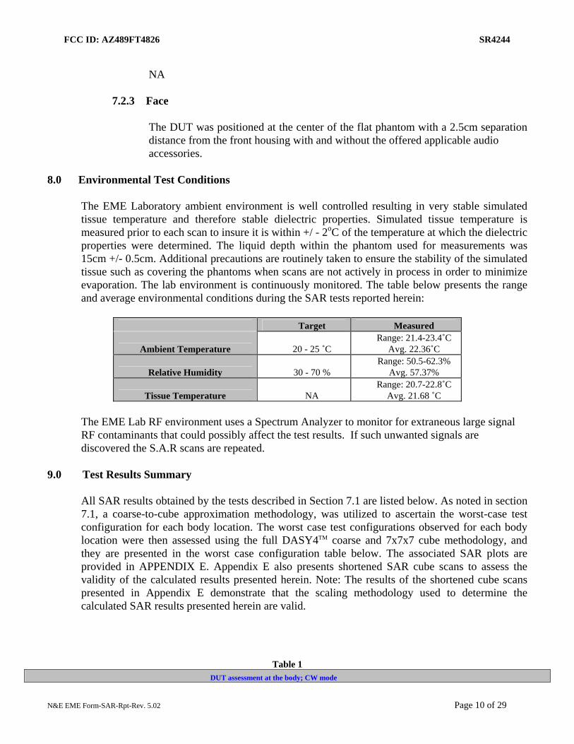
7.2.3 Face
The DUT was positioned at the center of the flat phantom with a 2.5cm separation distance from the front housing with and without the offered applicable audio accessories.
8.0 Environmental Test Conditions The EME Laboratory ambient environment is well controlled resulting in very stable simulated tissue temperature and therefore stable dielectric properties. Simulated tissue temperature is measured prior to each scan to insure it is within +/ - 2oC of the temperature at which the dielectric properties were determined. The liquid depth within the phantom used for measurements was 15cm +/- 0.5cm. Additional precautions are routinely taken to ensure the stability of the simulated tissue such as covering the phantoms when scans are not actively in process in order to minimize evaporation. The lab environment is continuously monitored. The table below presents the range and average environmental conditions during the SAR tests reported herein:
Target Measured
Ambient Temperature 20 - 25 ˚C Range: 21.4-23.4˚C
Avg. 22.36˚C
Relative Humidity 30 - 70 % Range: 50.5-62.3%
Avg. 57.37%
Tissue Temperature NA Range: 20.7-22.8˚C
Avg. 21.68 ˚C
The EME Lab RF environment uses a Spectrum Analyzer to monitor for extraneous large signal RF contaminants that could possibly affect the test results. If such unwanted signals are discovered the S.A.R scans are repeated.
9.0 Test Results Summary
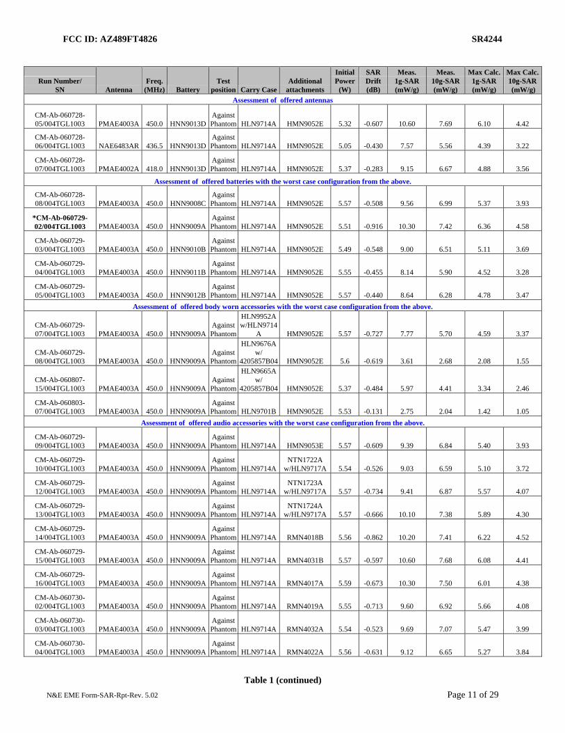
All SAR results obtained by the tests described in Section 7.1 are listed below. As noted in section 7.1, a coarse-to-cube approximation methodology, was utilized to ascertain the worst-case test configuration for each body location. The worst case test configurations observed for each body location were then assessed using the full DASY4TM coarse and 7x7x7 cube methodology, and they are presented in the worst case configuration table below. The associated SAR plots are provided in APPENDIX E. Appendix E also presents shortened SAR cube scans to assess the validity of the calculated results presented herein. Note: The results of the shortened cube scans presented in Appendix E demonstrate that the scaling methodology used to determine the calculated SAR results presented herein are valid.
Table 1 DUT assessment at the body; CW mode
FCC ID: AZ489FT4826 SR4244
N&E EME Form-SAR-Rpt-Rev. 5.02 Page 11 of 29
Run Number/ SN Antenna
Freq. (MHz) Battery
Test position Carry Case
Additional attachments
Initial Power
(W)
SAR Drift (dB)
Meas. 1g-SAR (mW/g)
Meas. 10g-SAR (mW/g)
Max Calc.1g-SAR (mW/g)
Max Calc. 10g-SAR (mW/g)
Assessment of offered antennas
CM-Ab-060728-05/004TGL1003 PMAE4003A 450.0 HNN9013D
Against Phantom HLN9714A HMN9052E 5.32 -0.607 10.60 7.69 6.10 4.42
CM-Ab-060728-06/004TGL1003 NAE6483AR 436.5 HNN9013D
Against Phantom HLN9714A HMN9052E 5.05 -0.430 7.57 5.56 4.39 3.22
CM-Ab-060728-07/004TGL1003 PMAE4002A 418.0 HNN9013D
Against Phantom HLN9714A HMN9052E 5.37 -0.283 9.15 6.67 4.88 3.56
Assessment of offered batteries with the worst case configuration from the above.
CM-Ab-060728-08/004TGL1003 PMAE4003A 450.0 HNN9008C
Against Phantom HLN9714A HMN9052E 5.57 -0.508 9.56 6.99 5.37 3.93
*CM-Ab-060729-02/004TGL1003 PMAE4003A 450.0 HNN9009A
Against Phantom HLN9714A HMN9052E 5.51 -0.916 10.30 7.42 6.36 4.58
CM-Ab-060729-03/004TGL1003 PMAE4003A 450.0 HNN9010B
Against Phantom HLN9714A HMN9052E 5.49 -0.548 9.00 6.51 5.11 3.69
CM-Ab-060729-04/004TGL1003 PMAE4003A 450.0 HNN9011B
Against Phantom HLN9714A HMN9052E 5.55 -0.455 8.14 5.90 4.52 3.28
CM-Ab-060729-05/004TGL1003 PMAE4003A 450.0 HNN9012B
Against Phantom HLN9714A HMN9052E 5.57 -0.440 8.64 6.28 4.78 3.47
Assessment of offered body worn accessories with the worst case configuration from the above.
CM-Ab-060729-07/004TGL1003 PMAE4003A 450.0 HNN9009A
Against Phantom
HLN9952A w/HLN9714
A HMN9052E 5.57 -0.727 7.77 5.70 4.59 3.37
CM-Ab-060729-08/004TGL1003 PMAE4003A 450.0 HNN9009A
Against Phantom
HLN9676A w/
4205857B04 HMN9052E 5.6 -0.619 3.61 2.68 2.08 1.55
CM-Ab-060807-15/004TGL1003 PMAE4003A 450.0 HNN9009A
Against Phantom
HLN9665A w/
4205857B04 HMN9052E 5.37 -0.484 5.97 4.41 3.34 2.46
CM-Ab-060803-07/004TGL1003 PMAE4003A 450.0 HNN9009A
Against Phantom HLN9701B HMN9052E 5.53 -0.131 2.75 2.04 1.42 1.05
Assessment of offered audio accessories with the worst case configuration from the above.
CM-Ab-060729-09/004TGL1003 PMAE4003A 450.0 HNN9009A
Against Phantom HLN9714A HMN9053E 5.57 -0.609 9.39 6.84 5.40 3.93
CM-Ab-060729-10/004TGL1003 PMAE4003A 450.0 HNN9009A
Against Phantom HLN9714A
NTN1722A w/HLN9717A 5.54 -0.526 9.03 6.59 5.10 3.72
CM-Ab-060729-12/004TGL1003 PMAE4003A 450.0 HNN9009A
Against Phantom HLN9714A
NTN1723A w/HLN9717A 5.57 -0.734 9.41 6.87 5.57 4.07
CM-Ab-060729-13/004TGL1003 PMAE4003A 450.0 HNN9009A
Against Phantom HLN9714A
NTN1724A w/HLN9717A 5.57 -0.666 10.10 7.38 5.89 4.30
CM-Ab-060729-14/004TGL1003 PMAE4003A 450.0 HNN9009A
Against Phantom HLN9714A RMN4018B 5.56 -0.862 10.20 7.41 6.22 4.52
CM-Ab-060729-15/004TGL1003 PMAE4003A 450.0 HNN9009A
Against Phantom HLN9714A RMN4031B 5.57 -0.597 10.60 7.68 6.08 4.41
CM-Ab-060729-16/004TGL1003 PMAE4003A 450.0 HNN9009A
Against Phantom HLN9714A RMN4017A 5.59 -0.673 10.30 7.50 6.01 4.38
CM-Ab-060730-02/004TGL1003 PMAE4003A 450.0 HNN9009A
Against Phantom HLN9714A RMN4019A 5.55 -0.713 9.60 6.92 5.66 4.08
CM-Ab-060730-03/004TGL1003 PMAE4003A 450.0 HNN9009A
Against Phantom HLN9714A RMN4032A 5.54 -0.523 9.69 7.07 5.47 3.99
CM-Ab-060730-04/004TGL1003 PMAE4003A 450.0 HNN9009A
Against Phantom HLN9714A RMN4022A 5.56 -0.631 9.12 6.65 5.27 3.84
Table 1 (continued)

FCC ID: AZ489FT4826 SR4244
N&E EME Form-SAR-Rpt-Rev. 5.02 Page 12 of 29
DUT assessment at the body; CW mode
Run Number/ SN Antenna
Freq. (MHz) Battery
Test position Carry Case
Additional attachments
Initial Power
(W)
SAR Drift (dB)
Meas. 1g-SAR (mW/g)
Meas. 10g-SAR (mW/g)
Max Calc.1g-SAR (mW/g)
Max Calc. 10g-SAR (mW/g)
Assessment across the band of each offered antenna with the worst case configuration from the above.
CM-Ab-060730-05/004TGL1003 NAE6483AR 403.0 HNN9009A
Against Phantom HLN9714A HMN9052E 5.60 0.196 4.44 3.26 2.22 1.63
CM-Ab-060730-06/004TGL1003 NAE6483AR 436.5 HNN9009A
Against Phantom HLN9714A HMN9052E 5.60 0.252 3.31 2.43 1.66 1.22
CM-Ab-060730-07/004TGL1003 NAE6483AR 470.0 HNN9009A
Against Phantom HLN9714A HMN9052E 5.41 -0.676 2.82 2.04 1.65 1.19
CM-Ab-060730-08/004TGL1003 PMAE4002A 403.0 HNN9009A
Against Phantom HLN9714A HMN9052E 5.60 0.286 2.75 2.00 1.38 1.00
CM-Ab-060808-14/004TGL1003 PMAE4002A 418.0 HNN9009A
Against Phantom HLN9714A HMN9052E 5.46 -0.262 6.13 4.47 3.26 2.37
CM-Ab-060730-10/004TGL1003 PMAE4002A 433.0 HNN9009A
Against Phantom HLN9714A HMN9052E 5.05 -1.04 6.86 4.99 4.57 3.33
CM-Ab-060730-11/004TGL1003 PMAE4003A 430.0 HNN9009A
Against Phantom HLN9714A HMN9052E 5.06 -0.528 6.24 4.55 3.69 2.69
CM-Ab-060730-12/004TGL1003 PMAE4003A 470.0 HNN9009A
Against Phantom HLN9714A HMN9052E 5.55 -0.754 5.05 3.66 3.00 2.18
Assessment at 2.5cm separation
CM-Ab-060730-13/004TGL1003 PMAE4003A 450.0 HNN9009A
DUT back; ant
@2.5cm None HMN9052E 5.60 -0.639 8.52 6.22 4.94 3.60
CM-Ab-060730-15/004TGL1003 PMAE4003A 450.0 HNN9009A
DUT front @2.5cm None HMN9052E 5.62 -0.882 6.12 4.51 3.75 2.76
Table 2

FCC ID: AZ489FT4826 SR4244
N&E EME Form-SAR-Rpt-Rev. 5.02 Page 13 of 29
DUT assessment at the face; CW mode
Run Number/ SN Antenna
Freq. (MHz) Battery
Test position Carry Case
Additional attachments
Initial Power
(W)
SAR Drift (dB)
Meas. 1g-SAR (mW/g)
Meas. 10g-SAR (mW/g)
Max Calc.1g-SAR (mW/g)
Max Calc. 10g-SAR (mW/g)
Assessment of offered antennas
CM-Face-060801-03/004TGL1003 NAE6483AR 436.5 HNN9013D
DUT front 2.5cm None None 5.07 -0.471 6.51 4.84 3.79 2.82
CM-Face-060801-04/004TGL1003 PMAE4002A 418.0 HNN9013D
DUT front 2.5cm None None 5.12 -0.144 5.02 3.72 2.69 1.99
*CM-Face-060802-08/004TGL1003 PMAE4003B 450.0 HNN9013D
DUT front 2.5cm None None 5.37 -0.355 7.20 5.33 3.91 2.89
Assessment of offered batteries with the worst case configuration from the above.
CM-Face-060804-12/004TGL1003 PMAE4003A 450.0 HNN9008C
DUT front 2.5cm None None 5.50 -0.365 6.70 4.95 3.64 2.69
CM-Face-060804-13/004TGL1003 PMAE4003A 450.0 HNN9009A
DUT front 2.5cm None None 5.46 -0.279 6.62 4.90 3.53 2.61
CM-Face-060804-14/004TGL1003 PMAE4003A 450.0 HNN9010B
DUT front 2.5cm None None 5.05 -0.238 6.26 4.63 3.47 2.57
CM-Face-060804-15/004TGL1003 PMAE4003A 450.0 HNN9011B
DUT front 2.5cm None None 5.34 -0.311 6.18 4.58 3.32 2.46
CM-Face-060804-16/004TGL1003 PMAE4003A 450.0 HNN9012B
DUT front 2.5cm None None 5.56 -0.204 6.49 4.81 3.40 2.52
Assessment of offered audio accessories with the worst case configuration from the above.
CM-Face-060804-17/004TGL1003 PMAE4003A 450.0 HNN9013D
DUT front 2.5cm None RMN4021A 5.40 -0.351 6.45 4.78 3.50 2.59
Assessment across the band of each offered antenna with the worst case configuration from the above. CM-Face-060802-02/004TGL1003
NAE6483AR 403.0 HNN9013D
DUT front 2.5cm None None 5.33 0.138 2.99 2.22 1.50 1.11
CM-Face-060802-03/004TGL1003
NAE6483AR 470.0 HNN9013D
DUT front 2.5cm None None 5.04 -0.424 1.82 1.35 1.06 0.78
CM-Face-060802-04/004TGL1003
PMAE4002A 403.0 HNN9013D
DUT front 2.5cm None None 5.15 0.176 1.37 1.01 0.70 0.52
CM-Face-060802-06/004TGL1003
PMAE4002A 433.0 HNN9013D
DUT front 2.5cm None None 5.09 -0.313 6.64 4.92 3.72 2.75
CM-Face-060802-07/004TGL1003
PMAE4003A 430.0 HNN9013D
DUT front 2.5cm None None 5.08 -0.207 4.14 3.07 2.27 1.68
CM-Face-060802-09/004TGL1003
PMAE4003A 470.0 HNN9013D
DUT front 2.5cm None None 5.07 -0.490 3.46 2.57 2.02 1.50
Table 3

FCC ID: AZ489FT4826 SR4244
N&E EME Form-SAR-Rpt-Rev. 5.02 Page 14 of 29
Assessment with the worst case configuration at the body and face using the DASY 4 full coarse and 7x7x7 cube scan measurements.
Run Number/ SN Antenna
Freq. (MHz) Battery
Test position Carry Case
Additional attachments
Initial Power
(W)
SAR Drift (dB)
Meas. 1g-SAR (mW/g)
Meas. 10g-SAR (mW/g)
Max Calc.1g-SAR (mW/g)
Max Calc. 10g-SAR (mW/g)
CM-Ab-060731-09/004TGL1003 PMAE4003A 450.0 HNN9009A
Against Phantom HLN9714A HMN9052E 5.54 -0.807 8.79 6.36 5.29 3.83
CM-Ab-060731-10/004TGL1003 (Shorten Scan) PMAE4003A 450.0 HNN9009A
Against Phantom HLN9714A HMN9052E 5.55 -0.313 10.30 7.43 5.53 3.99
CM-Face-060803-04/004TGL1003 PMAE4003A 450.0 HNN9013D
DUT front
2.5cm None None 5.44 -0.495 7.20 5.39 4.03 3.02 CM-Face-060803-06/004TGL1003 (Shorten Scan) PMAE4003A 450.0 HNN9013D
DUT front
2.5cm None None 5.39 -0.205 7.75 5.82 4.06 3.05
9.1 Highest SAR results calculation methodology
The calculated maximum 1-gram and 10-gram averaged SAR results reported herein for the full DASY ™ coarse and 7x7x7 cube measurements are determined by scaling the measured SAR to account for power leveling variations and power slump. For this device the Maximum Calculated 1-gram and 10-gram averaged peak SAR is calculated using the following formula:
Max. Calc. 1-g/10-g Avg. SAR = ((SAR meas. / (10^(Pdrift/10)))*(Pmax/Pint))* DC% Pmax = Maximum Power (W)
Pint = Initial Power (W) Pdrift = DASY drift results (dB) - (for conservative results positive drifts are not accounted for) SARmeas. = Measured 1-g/10-g Avg. SAR (mW/g) DC % = Transmission mode duty cycle in % where applicable 50% duty cycle is applied for PTT operation.
10.0 Conclusion The highest Operational Maximum Calculated 1-gram and 10-gram average SAR values found for FCC ID: AZ489FT4826 models PMUE1678B. Max. Calc. : 1-g Avg. SAR: 5.54 W/kg (Body); 10-g Avg. SAR: 4.00 W/kg (Body) Max. Calc. : 1-g Avg. SAR: 4.06 W/kg (Face); 10-g Avg. SAR: 3.05 W/kg (Face)
These test results clearly demonstrate compliance with FCC Occupational/Controlled RF Exposure limits of 8.0 mW/g per the requirements of 47 CFR 2.1093(d).

FCC ID: AZ489FT4826 SR4244
N&E EME Form-SAR-Rpt-Rev. 5.02 Page 15 of 29
APPENDIX A Measurement Uncertainty

FCC ID: AZ489FT4826 SR4244
N&E EME Form-SAR-Rpt-Rev. 5.02 Page 16 of 29
Uncertainty Budget for Device Under Test: 30 – 3000 MHz h = i =
a b c d e =
f(d,k) f g c x f /
e c x g /
e k
Tol. Prob ci ci 1 g 10 g (± %) Dist (1 g)
(10 g) ui ui
Uncertainty Component IEEE 1528
section Div. (±%) (±%) vi Measurement System Probe Calibration E.2.1 5.9 N 1.00 1 1 5.9 5.9 ∞
Axial Isotropy E.2.2 4.7 R 1.73 0.70
7 0.707 1.9 1.9 ∞
Hemispherical Isotropy E.2.2 9.6 R 1.73 0.70
7 0.707 3.9 3.9 ∞ Boundary Effect E.2.3 1.0 R 1.73 1 1 0.6 0.6 ∞ Linearity E.2.4 4.7 R 1.73 1 1 2.7 2.7 ∞ System Detection Limits E.2.5 1.0 R 1.73 1 1 0.6 0.6 ∞ Readout Electronics E.2.6 0.3 N 1.00 1 1 0.3 0.3 ∞ Response Time E.2.7 1.1 R 1.73 1 1 0.6 0.6 ∞ Integration Time E.2.8 1.1 R 1.73 1 1 0.6 0.6 ∞ RF Ambient Conditions - Noise E.6.1 3.0 R 1.73 1 1 1.7 1.7 ∞ RF Ambient Conditions - Reflections E.6.1 0.0 R 1.73 1 1 0.0 0.0 ∞ Probe Positioner Mech. Tolerance E.6.2 0.4 R 1.73 1 1 0.2 0.2 ∞ Probe Positioning w.r.t Phantom E.6.3 1.4 R 1.73 1 1 0.8 0.8 ∞ Max. SAR Evaluation (ext., int., avg.) E.5 3.4 R 1.73 1 1 2.0 2.0 ∞ Test sample Related Test Sample Positioning E.4.2 3.2 N 1.00 1 1 3.2 3.2 29 Device Holder Uncertainty E.4.1 4.0 N 1.00 1 1 4.0 4.0 8 SAR drift 6.6.2 5.0 R 1.73 1 1 2.9 2.9 ∞ Phantom and Tissue Parameters Phantom Uncertainty E.3.1 4.0 R 1.73 1 1 2.3 2.3 ∞ Liquid Conductivity (target) E.3.2 5.0 R 1.73 0.64 0.43 1.8 1.2 ∞ Liquid Conductivity (measurement) E.3.3 3.3 N 1.00 0.64 0.43 2.1 1.4 ∞ Liquid Permittivity (target) E.3.2 5.0 R 1.73 0.6 0.49 1.7 1.4 ∞ Liquid Permittivity (measurement) E.3.3 1.9 N 1.00 0.6 0.49 1.1 0.9 ∞ Combined Standard Uncertainty RSS 11 11 411 Expanded Uncertainty (95% CONFIDENCE LEVEL) k=2 22 22

FCC ID: AZ489FT4826 SR4244
N&E EME Form-SAR-Rpt-Rev. 5.02 Page 17 of 29
Uncertainty Budget for System Validation: 30 – 3000 MHz h = i =
a b c d e =
f(d,k) f g c x f /
e c x g /
e k
Tol. Prob. ci ci 1 g 10 g (± %) Dist. (1 g) (10 g) ui ui
Uncertainty Component
IEEE
1528
section Div. (±%) (±%) vi Measurement System Probe Calibration E.2.1 5.9 N 1.00 1 1 5.9 5.9 ∞
Axial Isotropy E.2.2 4.7 R 1.73 1 1 2.7 2.7 ∞
Spherical Isotropy E.2.2 9.6 R 1.73 0 0 0.0 0.0 ∞
Boundary Effect E.2.3 1.0 R 1.73 1 1 0.6 0.6 ∞
Linearity E.2.4 4.7 R 1.73 1 1 2.7 2.7 ∞
System Detection Limits E.2.5 1.0 R 1.73 1 1 0.6 0.6 ∞
Readout Electronics E.2.6 0.3 N 1.00 1 1 0.3 0.3 ∞
Response Time E.2.7 1.1 R 1.73 1 1 0.6 0.6 ∞
Integration Time E.2.8 0.0 R 1.73 1 1 0.0 0.0 ∞
RF Ambient Conditions - Noise E.6.1 3.0 R 1.73 1 1 1.7 1.7 ∞
RF Ambient Conditions - Reflections E.6.1 0.0 R 1.73 1 1 0.0 0.0 ∞
Probe Positioner Mechanical Tolerance E.6.2 0.4 R 1.73 1 1 0.2 0.2 ∞
Probe Positioning w.r.t. Phantom E.6.3 1.4 R 1.73 1 1 0.8 0.8 ∞
Max. SAR Evaluation (ext., int., avg.) E.5 3.4 R 1.73 1 1 2.0 2.0 ∞
Dipole
Dipole Axis to Liquid Distance 8,
E.4.2 2.0 R 1.73 1 1 1.2 1.2 ∞ Input Power and SAR Drift Measurement 8, 6.6.2 5.0 R 1.73 1 1 2.9 2.9 ∞
Phantom and Tissue Parameters Phantom Uncertainty E.3.1 4.0 R 1.73 1 1 2.3 2.3 ∞
Liquid Conductivity (target) E.3.2 5.0 R 1.73 0.64 0.43 1.8 1.2 ∞
Liquid Conductivity (measurement) E.3.3 3.3 R 1.73 0.64 0.43 1.2 0.8 ∞
Liquid Permittivity (target) E.3.2 5.0 R 1.73 0.6 0.49 1.7 1.4 ∞
Liquid Permittivity (measurement) E.3.3 1.9 R 1.73 0.6 0.49 0.6 0.5 ∞
Combined Standard Uncertainty RSS 9 9 9999
9 Expanded Uncertainty (95% CONFIDENCE LEVEL) k=2 18 17
Notes for Tables 1 and 2 a) Column headings a-k are given for reference. b) Tol. - tolerance in influence quantity. c) Prob. Dist. – Probability distribution d) N, R - normal, rectangular probability distributions e) Div. - divisor used to translate tolerance into normally distributed standard uncertainty f) ci - sensitivity coefficient that should be applied to convert the variability of the uncertainty component into a variability of SAR. g) ui – SAR uncertainty h) vi - degrees of freedom for standard uncertainty and effective degrees of freedom for the expanded uncertainty.
FCC ID: AZ489FT4826 SR4244
N&E EME Form-SAR-Rpt-Rev. 5.02 Page 18 of 29
Appendix B
Probe Calibration Certificates

FCC ID: AZ489FT4826 SR4244
N&E EME Form-SAR-Rpt-Rev. 5.02 Page 19 of 29
FCC ID: AZ489FT4826 SR4244
N&E EME Form-SAR-Rpt-Rev. 5.02 Page 20 of 29

FCC ID: AZ489FT4826 SR4244
N&E EME Form-SAR-Rpt-Rev. 5.02 Page 21 of 29

FCC ID: AZ489FT4826 SR4244
N&E EME Form-SAR-Rpt-Rev. 5.02 Page 22 of 29

FCC ID: AZ489FT4826 SR4244
N&E EME Form-SAR-Rpt-Rev. 5.02 Page 23 of 29

FCC ID: AZ489FT4826 SR4244
N&E EME Form-SAR-Rpt-Rev. 5.02 Page 24 of 29

FCC ID: AZ489FT4826 SR4244
N&E EME Form-SAR-Rpt-Rev. 5.02 Page 25 of 29
FCC ID: AZ489FT4826 SR4244
N&E EME Form-SAR-Rpt-Rev. 5.02 Page 26 of 29
FCC ID: AZ489FT4826 SR4244
N&E EME Form-SAR-Rpt-Rev. 5.02 Page 27 of 29
FCC ID: AZ489FT4826 SR4244
N&E EME Form-SAR-Rpt-Rev. 5.02 Page 28 of 29
FCC ID: AZ489FT4826 SR4244
N&E EME Form-SAR-Rpt-Rev. 5.02 Page 29 of 29